WO2016059664A1 - クラッキングコンロッド用圧延鋼材 - Google Patents
クラッキングコンロッド用圧延鋼材 Download PDFInfo
- Publication number
- WO2016059664A1 WO2016059664A1 PCT/JP2014/005274 JP2014005274W WO2016059664A1 WO 2016059664 A1 WO2016059664 A1 WO 2016059664A1 JP 2014005274 W JP2014005274 W JP 2014005274W WO 2016059664 A1 WO2016059664 A1 WO 2016059664A1
- Authority
- WO
- WIPO (PCT)
- Prior art keywords
- content
- steel
- cracking
- ratio
- rolled steel
- Prior art date
- Legal status (The legal status is an assumption and is not a legal conclusion. Google has not performed a legal analysis and makes no representation as to the accuracy of the status listed.)
- Ceased
Links
Images

Classifications
-
- C—CHEMISTRY; METALLURGY
- C22—METALLURGY; FERROUS OR NON-FERROUS ALLOYS; TREATMENT OF ALLOYS OR NON-FERROUS METALS
- C22C—ALLOYS
- C22C38/00—Ferrous alloys, e.g. steel alloys
- C22C38/18—Ferrous alloys, e.g. steel alloys containing chromium
- C22C38/24—Ferrous alloys, e.g. steel alloys containing chromium with vanadium
-
- C—CHEMISTRY; METALLURGY
- C21—METALLURGY OF IRON
- C21D—MODIFYING THE PHYSICAL STRUCTURE OF FERROUS METALS; GENERAL DEVICES FOR HEAT TREATMENT OF FERROUS OR NON-FERROUS METALS OR ALLOYS; MAKING METAL MALLEABLE, e.g. BY DECARBURISATION OR TEMPERING
- C21D8/00—Modifying the physical properties of ferrous metals or ferrous alloys by deformation combined with, or followed by, heat treatment
- C21D8/06—Modifying the physical properties of ferrous metals or ferrous alloys by deformation combined with, or followed by, heat treatment during manufacturing of rods or wires
-
- C—CHEMISTRY; METALLURGY
- C22—METALLURGY; FERROUS OR NON-FERROUS ALLOYS; TREATMENT OF ALLOYS OR NON-FERROUS METALS
- C22C—ALLOYS
- C22C38/00—Ferrous alloys, e.g. steel alloys
-
- C—CHEMISTRY; METALLURGY
- C22—METALLURGY; FERROUS OR NON-FERROUS ALLOYS; TREATMENT OF ALLOYS OR NON-FERROUS METALS
- C22C—ALLOYS
- C22C38/00—Ferrous alloys, e.g. steel alloys
- C22C38/001—Ferrous alloys, e.g. steel alloys containing N
-
- C—CHEMISTRY; METALLURGY
- C22—METALLURGY; FERROUS OR NON-FERROUS ALLOYS; TREATMENT OF ALLOYS OR NON-FERROUS METALS
- C22C—ALLOYS
- C22C38/00—Ferrous alloys, e.g. steel alloys
- C22C38/02—Ferrous alloys, e.g. steel alloys containing silicon
-
- C—CHEMISTRY; METALLURGY
- C22—METALLURGY; FERROUS OR NON-FERROUS ALLOYS; TREATMENT OF ALLOYS OR NON-FERROUS METALS
- C22C—ALLOYS
- C22C38/00—Ferrous alloys, e.g. steel alloys
- C22C38/04—Ferrous alloys, e.g. steel alloys containing manganese
-
- C—CHEMISTRY; METALLURGY
- C22—METALLURGY; FERROUS OR NON-FERROUS ALLOYS; TREATMENT OF ALLOYS OR NON-FERROUS METALS
- C22C—ALLOYS
- C22C38/00—Ferrous alloys, e.g. steel alloys
- C22C38/18—Ferrous alloys, e.g. steel alloys containing chromium
- C22C38/28—Ferrous alloys, e.g. steel alloys containing chromium with titanium or zirconium
-
- C—CHEMISTRY; METALLURGY
- C22—METALLURGY; FERROUS OR NON-FERROUS ALLOYS; TREATMENT OF ALLOYS OR NON-FERROUS METALS
- C22C—ALLOYS
- C22C38/00—Ferrous alloys, e.g. steel alloys
- C22C38/18—Ferrous alloys, e.g. steel alloys containing chromium
- C22C38/40—Ferrous alloys, e.g. steel alloys containing chromium with nickel
- C22C38/42—Ferrous alloys, e.g. steel alloys containing chromium with nickel with copper
-
- C—CHEMISTRY; METALLURGY
- C22—METALLURGY; FERROUS OR NON-FERROUS ALLOYS; TREATMENT OF ALLOYS OR NON-FERROUS METALS
- C22C—ALLOYS
- C22C38/00—Ferrous alloys, e.g. steel alloys
- C22C38/18—Ferrous alloys, e.g. steel alloys containing chromium
- C22C38/40—Ferrous alloys, e.g. steel alloys containing chromium with nickel
- C22C38/44—Ferrous alloys, e.g. steel alloys containing chromium with nickel with molybdenum or tungsten
-
- C—CHEMISTRY; METALLURGY
- C22—METALLURGY; FERROUS OR NON-FERROUS ALLOYS; TREATMENT OF ALLOYS OR NON-FERROUS METALS
- C22C—ALLOYS
- C22C38/00—Ferrous alloys, e.g. steel alloys
- C22C38/18—Ferrous alloys, e.g. steel alloys containing chromium
- C22C38/40—Ferrous alloys, e.g. steel alloys containing chromium with nickel
- C22C38/46—Ferrous alloys, e.g. steel alloys containing chromium with nickel with vanadium
-
- C—CHEMISTRY; METALLURGY
- C22—METALLURGY; FERROUS OR NON-FERROUS ALLOYS; TREATMENT OF ALLOYS OR NON-FERROUS METALS
- C22C—ALLOYS
- C22C38/00—Ferrous alloys, e.g. steel alloys
- C22C38/18—Ferrous alloys, e.g. steel alloys containing chromium
- C22C38/40—Ferrous alloys, e.g. steel alloys containing chromium with nickel
- C22C38/50—Ferrous alloys, e.g. steel alloys containing chromium with nickel with titanium or zirconium
-
- C—CHEMISTRY; METALLURGY
- C22—METALLURGY; FERROUS OR NON-FERROUS ALLOYS; TREATMENT OF ALLOYS OR NON-FERROUS METALS
- C22C—ALLOYS
- C22C38/00—Ferrous alloys, e.g. steel alloys
- C22C38/60—Ferrous alloys, e.g. steel alloys containing lead, selenium, tellurium, or antimony, or more than 0.04% by weight of sulfur
-
- C—CHEMISTRY; METALLURGY
- C21—METALLURGY OF IRON
- C21D—MODIFYING THE PHYSICAL STRUCTURE OF FERROUS METALS; GENERAL DEVICES FOR HEAT TREATMENT OF FERROUS OR NON-FERROUS METALS OR ALLOYS; MAKING METAL MALLEABLE, e.g. BY DECARBURISATION OR TEMPERING
- C21D2211/00—Microstructure comprising significant phases
- C21D2211/004—Dispersions; Precipitations
-
- C—CHEMISTRY; METALLURGY
- C21—METALLURGY OF IRON
- C21D—MODIFYING THE PHYSICAL STRUCTURE OF FERROUS METALS; GENERAL DEVICES FOR HEAT TREATMENT OF FERROUS OR NON-FERROUS METALS OR ALLOYS; MAKING METAL MALLEABLE, e.g. BY DECARBURISATION OR TEMPERING
- C21D7/00—Modifying the physical properties of iron or steel by deformation
- C21D7/13—Modifying the physical properties of iron or steel by deformation by hot working
Definitions
- the present invention relates to a steel material, and more particularly to a rolled steel material for cracking connecting rods.
- the connecting rod is used for engines such as automobiles.
- the connecting rod connects the piston and the crankshaft, and converts the vertical movement of the piston into the rotational movement of the crank.
- FIG. 1 is a front view of a conventional connecting rod 1.
- the conventional connecting rod 1 includes a large end portion 10, a flange portion 20, and a small end portion 30.
- the large end portion 10 is disposed at one end of the flange portion 20, and the small end portion 30 is disposed at the other end of the flange portion 20.
- the large end 10 is connected to the crankpin.
- the small end 30 is connected to the piston.
- the conventional connecting rod 1 includes two parts (a cap 40 and a rod 50). One end portions of the cap 40 and the rod 50 correspond to the large end portion 10. Other parts than the one end of the rod 50 correspond to the flange 20 and the small end 30.
- the large end portion 10 and the small end portion 30 are formed by cutting. For this reason, the connecting rod 1 is required to have high machinability.
- the connecting rod 1 receives a load from surrounding members during engine operation.
- further downsizing of the connecting rod 1 and improvement of in-cylinder pressure in the cylinder have been demanded in order to save fuel.
- the connecting rod 1 is required to have an excellent buckling strength that can cope with an explosion load transmitted from the piston even if the flange portion 20 is thinned.
- the buckling strength strongly depends on the yield strength of the material. Therefore, the connecting rod is required to have high yield strength as well as high machinability.
- the cap 40 and the rod 50 are separately manufactured as described above. Therefore, a knock pin processing step is performed for positioning the cap 40 and the rod 50. Further, a cutting process is performed on the mating surface of the cap 40 and the rod 50. Therefore, cracking connecting rods that can omit these steps are beginning to spread.
- the cracking connecting rod after integrally forming the connecting rod, the large end portion is broken and divided into two parts (corresponding to the cap 40 and the rod 50). And two parts divided
- Patent Document 1 JP 2010-180473
- Patent Document 2 JP 2004-301324 A Patent Document 3
- Patent Document 4 International Publication No. 2012/164710
- Patent Document 5 Japanese Patent Application Laid-Open No. 2011-084767
- Patent Document 6 International Publication No. 2012/157455
- Patent Document 1 describes the following matters.
- the steel for cracking connecting rod contains, by weight, C: 0.6 to 0.75%, Mn: 0.25 to 0.50, S: 0.04 to 0.12%, the balance being Fe, and , Consisting of up to 1.2% impurities. Mn / S is 3.0 or more.
- the structure of the steel is 100% pearlite and the particle size measured according to ASTM E112-88 is 3-8.
- Patent Document 2 discloses the following matters.
- Cracking connecting rod steel is composed of ferrite and pearlite type non-tempered steel containing 0.20 to 0.60% C by mass.
- the buttocks are coined.
- the steel for cracking connecting rods contains C, N, Ti, Mn and Cr as essential elements, and contains Si, P, S, V, Pb, Te, Ca and Bi as optional elements.
- Mn is 0.30 to 1.50%
- Cr is 0.05 to 1.00%
- N is 0.005 to 0.030%
- Ti is 0.20% or less.
- Ti ⁇ 3.4N + 0.02 is satisfied.
- the 0.2% proof stress of the large end is lower than 650 MPa. Further, the 0.2% proof stress of the coined heel portion is higher than 700 MPa.
- Patent Document 3 discloses the following matters.
- Non-tempered connecting rods are in mass%, C: 0.25 to 0.35%, Si: 0.50 to 0.70%, Mn: 0.60 to 0.90%, P: 0.040 to 0.070%, S: 0.040 to 0.130%, Cr: 0.10 to 0.20%, V: 0.15 to 0.20%, Ti: 0.15 to 0.20% and N : 0.002% to 0.020%, with the balance being Fe and impurities.
- the Ceq value defined by the formula (1) is less than 0.80.
- the structure of the large end is composed of ferrite and pearlite.
- the total thigh hardness is 255 to 320 in terms of Vickers hardness.
- the hardness of the ferrite at the large end is 250 or more in terms of Vickers hardness. Furthermore, the ratio of the hardness of the ferrite to the total hardness of the large end is 0.80 or more.
- Ceq C + (Si / 10) + (Mn / 5) + (5Cr / 22) + 1.65V ⁇ (5S / 7) (1)
- Patent Document 4 discloses the following matters. Steel bars for non-tempered connecting rods are in mass%, C: 0.25 to 0.35%, Si: 0.40 to 0.70%, Mn: more than 0.65% and 0.90% or less, P: 0.040 to 0.070%, S: 0.040 to 0.130%, Cr: 0.10 to 0.30%, Cu: 0.05 to 0.40%, Ni: 0.05 to 0.30%, Mo: 0.01 to 0.15%, V: 0.12 to 0.20%, Ti: more than 0.150 and 0.200% or less, Al: 0.002 to 0.100 % And N: 0.020 or less, with the balance being Fe and impurities. Fn1 defined by the following formula is 0.60 to 0.80, and Fn2 defined by the following formula is 7 or more.
- More than 90% of the structure of the non-tempered connecting rod steel is a ferrite and pearlite structure.
- the ratio of ferrite in the ferrite and pearlite structure is 40% or more.
- Fn1 C + (Si / 10) + (Mn / 5) + (5Cr / 22) + 1.65V ⁇ (5S / 7) + (Cu / 33) + (Ni / 20) + (Mo / 10)
- Fn2 (Mn + Ti) / S
- Patent Document 5 discloses the following matters.
- the manufacturing method of a cracking connecting rod includes a step of preparing a steel material, a step of heating the steel material to a temperature range of 1200 ° C. to 1300 ° C., and a processing rate of 50% or more in at least a predetermined portion of the steel material at a temperature of 1000 ° C. or higher.
- the cracking connecting rod to be produced is, by mass, C: 0.16-0.35%, Si: 0.1-1.0%, Mn: 0.3-1.0%, P: 0.040- 0.070%, S: 0.080 to 0.130%, V: 0.10 to 0.35%, and Ti: 0.08 to 0.20%.
- the hardness in a predetermined part is at least 250 HV or more.
- Patent Document 6 further discloses a non-tempered steel having a low V content. Specifically, Patent Document 6 describes the following matters. Non-tempered steel is in mass%, C: 0.27-0.40%, Si: 0.15-0.70%, Mn: 0.55-1.50%, P: 0.010-0 0.070%, S: 0.05 to 0.15%, Cr: 0.10 to 0.60%, V: 0.030% or more and less than 0.150%, Ti: over 0.100%, 0 200% or less, Al: 0.002 to 0.050% and N: 0.002 to 0.020%, with the balance being Fe and impurities. Et represented by the following formula is less than 0. Ceq represented by the following formula is more than 0.60 and less than 0.80.
- the steel for cracking connecting rods of Patent Document 1 is widely used in Europe.
- the cracking connecting rod steel of Patent Document 1 may have low yield strength and machinability.
- the yield strength of the cracking connecting rod steel described in Patent Document 2 is high. However, cracking may be low.
- the production conditions for hot forging for example, the heating temperature before hot forging may vary from production site to production site. If the heating temperature before hot forging varies, even if the cracking connecting rod is manufactured by the steel materials and the manufacturing method described in Patent Documents 1 to 6, the cracking property, yield strength, and machinability of the cracking connecting rod Either of them may be low.
- An object of the present invention is to provide a rolled steel material for cracking connecting rods that has high cracking property, high yield strength, and high machinability after hot forging even if the heating temperature during hot forging varies. .
- the rolled steel material for cracking connecting rods is, in mass%, C: 0.30 to 0.40%, Si: 0.60 to 1.00%, Mn: 0.50 to 1.00%, P : 0.04 to 0.07%, S: 0.04 to 0.13%, Cr: 0.10 to 0.30%, V: 0.05 to 0.14%, Ti: 0.15% Over 0.20% or less, N: 0.002 to 0.020%, Cu: 0 to 0.40%, Ni: 0 to 0.30%, Mo: 0 to 0.10%, Pb: 0 to 0.30%, Te: 0 to 0.30%, Ca: 0 to 0.010%, and Bi: 0 to 0.30%, with the balance being Fe and impurities,
- the defined fn1 has a chemical composition of 0.65 to 0.80.
- the ratio of the V content in the coarse precipitate having a particle diameter of 200 nm or more to the V content in the rolled steel for cracking connecting rod is 70% or less.
- the ratio of the Ti content in the coarse precipitate to the Ti content in the rolled steel for cracking connecting rod is 50% or more.
- the rolled steel material for cracking connecting rods according to the present embodiment can obtain high cracking property, high yield strength, and high machinability after hot forging even if the heating temperature during hot forging varies.
- FIG. 1 is a side view of a conventional connecting rod.
- the rolled steel material for cracking connecting rods is, in mass%, C: 0.30 to 0.40%, Si: 0.60 to 1.00%, Mn: 0.50 to 1.00%, P : 0.04 to 0.07%, S: 0.04 to 0.13%, Cr: 0.10 to 0.30%, V: 0.05 to 0.14%, Ti: 0.15% Over 0.20% or less, N: 0.002 to 0.020%, Cu: 0 to 0.40%, Ni: 0 to 0.30%, Mo: 0 to 0.10%, Pb: 0 to 0.30%, Te: 0 to 0.30%, Ca: 0 to 0.010%, and Bi: 0 to 0.30%, with the balance being Fe and impurities,
- the defined fn1 has a chemical composition of 0.65 to 0.80.
- the ratio of the V content in the coarse precipitate having a particle diameter of 200 nm or more to the V content in the rolled steel for cracking connecting rod is 70% or less.
- the ratio of the Ti content in the coarse precipitate to the Ti content in the rolled steel for cracking connecting rod is 50% or more.
- fn1 defined by the formula (1) is in the range of 0.65 to 0.80. Therefore, excellent yield strength and machinability can be obtained.
- the ratio of the V content in the coarse precipitate having a particle diameter of 200 nm or more to the V content in the rolled steel for cracking connecting rod is 70% or less.
- fine V precipitates are easily dissolved. Therefore, even if the heating temperature in the hot forging process is low (for example, about 1000 ° C.), V is likely to be dissolved by heating.
- the solid solution V is precipitated as a carbide in the cooling process of hot forging. As a result, even if the heating temperature in the hot forging process varies, the steel material after hot forging can stably obtain excellent yield strength.
- the ratio of the Ti content in the coarse precipitates to the Ti content in the rolled steel for cracking connecting rod is 50% or more.
- Ti forms sulfides and carbosulfides to enhance the machinability of steel. Further, Ti partially dissolves in the steel during heating in the hot forging process. The solid solution Ti forms carbides during subsequent cooling, embrittles ferrite, and improves cracking properties. However, if the amount of Ti dissolved in the hot forging process is too high, the steel structure after cooling becomes bainite. In this case, cracking properties are reduced. If the solid solution amount of Ti is too high, the tensile strength of the steel material becomes too high, and the machinability deteriorates.
- the Ti precipitate (precipitate containing Ti) can be prevented from being excessively dissolved during heating in the hot forging step.
- the ratio of the Ti content in the coarse precipitate is 50% or more, the fine Ti precipitate in the steel is sufficiently small. Therefore, even when the heating temperature in the hot forging process is high (for example, 1280 ° C.), Ti precipitates are difficult to dissolve (that is, Ti is hard to dissolve), and cracking properties and machinability are reduced. Can be suppressed.
- the rolled steel material for cracking connecting rods of the present embodiment has high cracking property, high yield strength, and high machinability after hot forging even if the heating temperature during hot forging varies.
- the chemical composition is one or two selected from the group consisting of Cu: 0.01 to 0.40%, Ni: 0.01 to 0.30%, and Mo: 0.01 to 0.10%. It may contain seeds or more.
- the chemical composition also includes Pb: 0.05 to 0.30%, Te: 0.0003 to 0.30%, Ca: 0.0003 to 0.010%, and Bi: 0.0003 to 0.30. You may contain 1 type, or 2 or more types selected from the group which consists of%.
- the chemical composition of the rolled steel material for cracking connecting rods according to the present embodiment contains the following elements.
- C 0.30 to 0.40% Carbon (C) increases the strength of the steel. If the C content is too low, this effect cannot be obtained. On the other hand, if the C content is too high, the hardness of the steel material increases, and the machinability decreases. Therefore, the C content is 0.30 to 0.40%.
- the minimum with preferable C content is higher than 0.30%, More preferably, it is 0.31%, More preferably, it is 0.32%.
- the upper limit with preferable C content is less than 0.40%, More preferably, it is 0.39%, More preferably, it is 0.38%.
- Si 0.60 to 1.00% Silicon (Si) deoxidizes steel. Si further dissolves in the steel to increase the strength of the steel. If the Si content is too low, this effect cannot be obtained. On the other hand, if the Si content is too high, the above effect is saturated. If the Si content is too high, the hot workability of the steel further decreases and the manufacturing cost of the steel material also increases. Therefore, the Si content is 0.60 to 1.00%.
- the minimum with preferable Si content is higher than 0.60%, More preferably, it is 0.62%, More preferably, it is 0.65%.
- the upper limit with preferable Si content is less than 1.00%, More preferably, it is 0.95%, More preferably, it is 0.90%.
- Mn 0.50 to 1.00%
- Manganese (Mn) deoxidizes steel. Mn further increases the strength of the steel. If the Mn content is too low, these effects cannot be obtained. On the other hand, if the Mn content is too high, the hot workability of the steel decreases. If the Mn content is too high, the hardenability is further increased, and bainite is generated in the steel structure. In this case, the cracking property of steel is lowered. Therefore, the Mn content is 0.50 to 1.00%.
- the minimum with preferable Mn content is higher than 0.50%, More preferably, it is 0.60%, More preferably, it is 0.65%.
- the upper limit with preferable Mn content is less than 1.00%, More preferably, it is 0.95%, More preferably, it is 0.90%.
- P 0.04 to 0.07% Phosphorus (P) segregates at the grain boundaries and embrittles the steel. Therefore, the fracture surface of the cracking connecting rod after the fracture split becomes smooth. As a result, the accuracy of assembling the cracking connecting rod after the fracture split is increased. If the P content is too low, this effect cannot be obtained. On the other hand, if P content is too high, the hot workability of steel will fall. Therefore, the P content is 0.04 to 0.07%.
- the minimum with preferable P content is higher than 0.04%, More preferably, it is 0.042%, More preferably, it is 0.045%.
- the upper limit with preferable P content is less than 0.07%, More preferably, it is 0.068%, More preferably, it is 0.065%.
- S 0.04 to 0.13%
- Sulfur (S) combines with Mn and Ti to form sulfides and enhances the machinability of steel. If the S content is too low, this effect cannot be obtained. On the other hand, if the S content is too high, the hot workability of the steel decreases. Therefore, the S content is 0.04 to 0.13%.
- the minimum with preferable S content is higher than 0.04%, More preferably, it is 0.045%, More preferably, it is 0.05%.
- the upper limit with preferable S content is less than 0.13%, More preferably, it is 0.125%, More preferably, it is 0.12%.
- Chromium (Cr) increases the strength of the steel. If the Cr content is too low, this effect cannot be obtained. On the other hand, if the Cr content is too high, the hardenability of the steel increases and bainite is generated in the steel structure. In this case, the cracking property of steel is lowered. If the Cr content is too high, the production cost further increases. Therefore, the Cr content is 0.10 to 0.30%.
- the minimum with preferable Cr content is higher than 0.10%, More preferably, it is 0.11%, More preferably, it is 0.12%.
- the upper limit with preferable Cr content is less than 0.30%, More preferably, it is 0.25%, More preferably, it is 0.20%.
- V Vanadium (V) precipitates as carbide in the ferrite during the cooling process after hot forging, and increases the yield strength of the steel. V is further contained together with Ti to enhance the cracking property of steel. If the V content is too low, these effects cannot be obtained. On the other hand, if the V content is too high, not only the production cost of steel becomes extremely high, but also the machinability decreases. Therefore, the V content is 0.05 to 0.14%.
- the minimum with preferable V content is higher than 0.05%, More preferably, it is 0.06%, More preferably, it is 0.07%.
- the minimum with preferable V content is less than 0.14%, More preferably, it is 0.13%, More preferably, it is less than 0.13%.
- Titanium (Ti) precipitates in the steel as a carbide or nitride, and increases the strength of the steel. Ti further produces sulfides or carbosulfides to enhance the machinability of the steel.
- the Ti content is more than 0.15% and 0.20% or less.
- the upper limit with preferable Ti content is less than 0.20%, More preferably, it is 0.19%.
- N 0.002 to 0.020% Nitrogen (N) combines with Ti to form nitrides and increases the strength of the steel. If the N content is too low, this effect cannot be obtained. On the other hand, if the N content is too high, this effect is saturated. Therefore, the N content is 0.002 to 0.020%.
- the minimum with preferable N content is higher than 0.002%, More preferably, it is 0.003%, More preferably, it is 0.004%.
- the upper limit with preferable N content is less than 0.020%, More preferably, it is 0.019%, More preferably, it is 0.018%.
- the balance of the chemical composition of the rolled steel for cracking connecting rod according to the present embodiment is composed of Fe and impurities.
- the impurities are mixed from ore as a raw material, scrap, or production environment when industrially producing steel materials, and are allowed within a range that does not adversely affect the steel materials of the present embodiment. Means what will be done.
- the chemical composition of the rolled steel material for cracking connecting rods according to the present embodiment may further include one or more selected from the group consisting of Cu, Ni, and Mo instead of part of Fe. These elements are arbitrary elements, and all increase the strength of steel.
- Cu 0 to 0.40% Copper (Cu) is an optional element and may not be contained. When contained, Cu dissolves in the steel and increases the strength of the steel. However, if the Cu content is too high, not only the production cost of steel increases, but also the machinability decreases. Therefore, the Cu content is 0 to 0.40%.
- the minimum with preferable Cu content is 0.01%, More preferably, it is 0.05%, More preferably, it is 0.10%.
- the upper limit with preferable Cu content is less than 0.40%, More preferably, it is 0.35%, More preferably, it is 0.30%.
- Nickel (Ni) is an optional element and may not be contained. When contained, Ni dissolves in the steel and increases the strength of the steel. However, if the Ni content is too high, not only the manufacturing cost increases, but also the Charpy impact value increases and the cracking property decreases. Therefore, the Ni content is 0 to 0.30%.
- the minimum with preferable Ni content is 0.01%, More preferably, it is 0.02%, More preferably, it is 0.05%.
- the upper limit with preferable Ni content is less than 0.30%, More preferably, it is 0.28%, More preferably, it is 0.25%.
- Mo Molybdenum
- Mo is an optional element and may not be contained. When contained, Mo dissolves in the steel and increases the strength of the steel. Mo further increases the strength of the steel by forming carbides in the steel. However, if the Mo content is too high, the hardenability increases and bainite is generated after hot forging. In this case, the cracking property of steel is lowered. Therefore, the Mo content is 0 to 0.10%.
- a preferable lower limit of the Mo content is 0.01%.
- the upper limit with preferable Mo content is less than 0.10%, More preferably, it is 0.09%, More preferably, it is 0.08%.
- the chemical composition of the rolled steel for cracking connecting rod according to the present embodiment may further include one or more selected from the group consisting of Pb, Te, Ca, and Bi, instead of a part of Fe. .
- These elements are arbitrary elements, and all enhance the machinability of steel.
- Pb 0 to 0.30%
- Lead (Pb) is an optional element and may not be contained. When contained, Pb increases the machinability of the steel. However, if the Pb content is too high, the hot workability of the steel decreases. Therefore, the Pb content is 0 to 0.30%.
- the minimum with preferable Pb content is 0.05%, More preferably, it is 0.10%.
- the upper limit with preferable Pb content is less than 0.30%, More preferably, it is 0.25%, More preferably, it is 0.20%.
- Te 0 to 0.30%
- Tellurium (Te) is an optional element and may not be contained. When contained, Te increases the machinability of the steel. However, if the Te content is too high, the hot workability of the steel decreases. Therefore, the Te content is 0 to 0.30%.
- the minimum with preferable Te content is 0.0003%, More preferably, it is 0.0005%, More preferably, it is 0.0010%.
- the upper limit with preferable Te content is less than 0.30%, More preferably, it is 0.25%, More preferably, it is 0.20%.
- Ca 0 to 0.010%
- Calcium (Ca) is an optional element and may not be contained. When contained, Ca increases the machinability of steel. However, if the Ca content is too high, the hot workability of the steel decreases. Therefore, the Ca content is 0 to 0.010%.
- the minimum with preferable Ca content is 0.0003%, More preferably, it is 0.0005%, More preferably, it is 0.0010%.
- the upper limit with preferable Ca content is less than 0.010%, More preferably, it is 0.008%, More preferably, it is 0.005%.
- Bi 0 to 0.30%
- Bismuth (Bi) is an optional element and may not be contained. When contained, Bi reduces the machinability of the steel.
- the Bi content is 0 to 0.30%.
- the minimum with preferable Bi content is 0.0003%, More preferably, it is 0.0005%, More preferably, it is 0.0010%.
- the upper limit with preferable Bi content is less than 0.30%, More preferably, it is 0.20%, More preferably, it is 0.10%.
- fn1 defined by the formula (1) is 0.65 to 0.80.
- fn1 C + Si / 10 + Mn / 5 + 5Cr / 22 + (Cu + Ni) / 20 + Mo / 2 + 33V / 20-5S / 7 (1)
- the content (mass%) of the corresponding element is substituted for the element symbol in the formula (1).
- “0” is assigned to the element symbol.
- Fn1 has a positive correlation with the tensile strength after hot forging of steel.
- fn1 is higher than 0.80, the tensile strength of the steel becomes too high and the machinability of the steel decreases.
- fn1 has a positive relationship with the yield strength of steel. Therefore, when fn1 is less than 0.65, the strength of the steel decreases. If fn1 is 0.65 to 0.80, the steel material has excellent strength and machinability.
- the preferable lower limit of fn1 is higher than 0.65, more preferably 0.66, and further preferably 0.67.
- the upper limit with preferable fn1 is less than 0.80, More preferably, it is 0.79, More preferably, it is 0.78.
- the ratio of the V content in the coarse precipitate having a particle diameter of 200 nm or more to the V content in the rolled steel for cracking connecting rod is 70% or less. Furthermore, the ratio of the Ti content in the coarse inclusion to the Ti content in the rolled steel for cracking connecting rod is 50% or more.
- V content in precipitate In this embodiment, V precipitates as a carbide. More specifically, V is once dissolved in the heating stage before hot forging, and precipitates as carbide at the austenite-ferrite interface during phase transformation during the cooling after hot forging (phase interface precipitation). Due to the phase interface precipitation of V carbide, the yield strength of the steel after hot forging increases. In order to obtain this effect, it is preferable that V is dissolved in austenite in the steel material before hot forging.
- V precipitates In order to promote solid solution of precipitates containing V (hereinafter referred to as V precipitates), it is effective to refine the V precipitates before hot forging and increase the total surface area of the V precipitates. . That is, it is effective for solid solution of V that the V precipitates in the rolled steel material for cracking connecting rods are fine. This is because if the V precipitate is fine and the total surface area is large, V is sufficiently dissolved in austenite during heating even if the heating temperature during hot forging is low (for example, 1000 ° C.).
- V ratio Rv defined by the equation (2) is If it is 70% or less, V precipitates in the rolled steel for cracking connecting rods are sufficiently fine. For this reason, V is sufficiently dissolved during heating in hot forging. Therefore, V carbide precipitates finely in the cooling process after hot forging, and high strength is obtained in the steel material after hot forging.
- Rv Vp / Vm ⁇ 100 (2)
- Vm and Vp are measured by the following method. 8 mm in diameter and 12 mm in length from any R / 2 part of a rolled steel material for round cracked cracking connecting rods (in the cross section of the steel material, including the region that bisects the center axis of the steel material and the outer peripheral surface of the steel material) Take a cylindrical specimen. The length of the cylindrical specimen is parallel to the axial direction of the steel material.
- Execute extraction residue analysis by electrolytic method using cylindrical test piece Specifically, the electrolysis time is adjusted with a constant current, and the surface layer from the surface of the cylindrical test piece to a depth of 200 ⁇ m is removed. Thereby, the impurities adhering to the surface of the cylindrical test piece are removed. After removing the surface layer, the electrolyte solution is replaced to prepare a new electrolyte solution.
- an AA electrolytic solution electrolytic solution containing 10 vol% acetylacetone and 1 vol% tetramethylammonium chloride with the balance being methanol
- electrolysis is performed on the cylindrical specimen.
- the electrolysis time is adjusted such that the current is constant at 1000 mA and the volume of the cylindrical test piece to be electrolyzed is 0.5 cm 3 .
- the electrolytic solution after electrolysis is filtered using a filter having a mesh size of 200 nm to obtain a residue.
- the obtained residue corresponds to a coarse precipitate.
- the V content in the rolled steel for cracking connecting rod is measured by the following method. Collect chips from a cylindrical specimen. The chip is obtained, for example, by turning a cylindrical test piece. The IPC issuance spectroscopic analysis method is performed on the chips to obtain the V content Vm (%). Using the obtained Vp and Vm, the V ratio Rv (%) is obtained from Equation (2).
- Ti precipitates as Ti carbide or Ti nitride, Ti sulfide or Ti carbon sulfide.
- Ti sulfide and Ti carbosulfide enhance the cracking property of steel materials.
- the heating temperature at the time of hot forging becomes a high temperature (for example, 1280 ° C.)
- the amount of Ti dissolved in the austenite is too large, Ti carbide is excessively precipitated in the cooling step after hot forging. In this case, the strength of the steel material after hot forging becomes too high, and the machinability deteriorates.
- Ti sulfide and Ti carbosulfide are not dissolved as much as possible during heating in hot forging.
- it is effective to coarsen the precipitate containing Ti before hot forging (hereinafter referred to as Ti precipitate) to reduce the surface area of the Ti precipitate. This is because Ti precipitates are coarse and their total surface area is small, even if the heating temperature during hot forging is high (for example, 1280 ° C.), Ti hardly dissolves in austenite during heating.
- the Ti content in the rolled steel for cracking connecting rod is defined as Tim (%), and the Ti content in the coarse precipitate is defined as Tip (%).
- the Ti ratio Rti defined by the formula (3) is 50% or more, the Ti precipitate in the rolled steel for cracking connecting rods is sufficiently coarse. Therefore, the excessive solid solution of Ti can be sufficiently suppressed at the time of heating for hot forging. Therefore, high machinability and cracking properties are obtained in the steel material after hot forging.
- Rti Tip / Tim ⁇ 100 (3)
- Tim and Tip are measured by the following method. Cylindrical test pieces are collected in the same manner as when Vm and Vp are obtained. Then, it electrolyzes on the same conditions as the case where Vm and Vp are calculated
- required, and a residue (coarse precipitate) is obtained. The residue is subjected to ICP emission spectroscopic analysis under the same conditions as when Vp is determined to determine the Ti content Tip (%) in the coarse precipitate. Specifically, Tip is obtained by the following equation. Ti content of the steel product in coarse precipitates of Tip 0.5cm 3 (mg) /0.5cm 3 steel mass (mg) ⁇ 100
- the chips are collected by the same method as that for obtaining Vm.
- An ICP emission spectroscopic analysis method is performed on the collected chips under the same conditions as when Vm is obtained, and Ti content Tim (%) in the steel material is obtained.
- Tip and Tim the Ti ratio Rti (%) is obtained by Equation (3).
- a preferable Ti ratio Rti is higher than 50%, more preferably 60% or more, and further preferably 70% or more.
- a molten steel having the above chemical composition is manufactured by a well-known method. Using the produced molten steel, a slab (slab or bloom) is produced by a continuous casting method. An ingot may be produced by ingot making using molten steel. You may manufacture a billet by a continuous casting method.
- the billet is manufactured by hot working the manufactured slab or ingot.
- Hot working is, for example, hot rolling.
- Hot rolling is performed using, for example, a block rolling mill and a continuous rolling mill in which a plurality of stands are arranged in a line.
- Manufacture steel bars (rolled steel for cracking connecting rods) using billets. Specifically, the billet is heated in a heating furnace (heating process). After heating, the billet is hot-rolled using a continuous rolling mill to obtain a rod-shaped rolled steel material for cracking conrods (hot rolling step). Hereinafter, each step will be described.
- the billet is heated at 1000 to 1100 ° C. If the heating temperature Tf is too low, the V precipitate in the billet is difficult to dissolve. Therefore, coarse V precipitates present in the billet are inherited even after hot rolling, and the coarse V precipitates in the steel after rolling increase. Therefore, the V ratio Rv exceeds 70%. Furthermore, if the heating temperature Tf is too low, Ti precipitates do not aggregate and grow during heating, and are difficult to coarsen. Therefore, there are few coarse Ti precipitates in the rolled steel material, and the Ti ratio Rti is less than 50%.
- the Ti ratio Rti is less than 50%.
- the V precipitate is properly dissolved, and the Ti precipitate aggregates and grows during heating and becomes coarse. If the conditions of the hot rolling process described later are also satisfied, in the rolled steel material for cracking connecting rod after rolling, the V ratio Rv is 70% or less and the Ti ratio Rti is 50% or more.
- the continuous rolling mill has a plurality of roll groups.
- the roll group includes a pair of rolls arranged around a rolling axis (pass line) or three or more rolls.
- the rolling axis means a line through which a billet to be rolled passes.
- the plurality of roll groups are arranged in a line. Each roll group is stored in a corresponding stand.
- the rolling speed Vr is 5 to 20 m / sec.
- the rolling speed Vr is defined as follows.
- time t0 seconds from when the tip of the billet is rolled by the first roll group to the last roll group used for rolling is measured.
- the time t0 can be measured by confirming the load applied to the leading roll and the load applied to the trailing roll.
- the rolling speed Vr (m / sec) is obtained by the equation (4).
- Vr distance on the rolling axis from the center of the leading roll group to the center of the trailing roll group / t0 (4)
- the rolling speed Vr means the rolling speed in the entire hot rolling. If the rolling speed Vr is too slow, heat generation due to hot rolling is unlikely to occur. Therefore, the temperature of the material to be rolled decreases during rolling. In this case, Ti precipitates hardly aggregate and grow during rolling. As a result, the Ti ratio Rti is less than 50%.
- the material to be rolled in which the reduction in area is 50 to 70% is water cooled for 1 to 3 seconds.
- a water cooling facility water cooling zone
- the roll groups between the stands
- the area reduction rate is 50 to 70%.
- the to-be-rolled material which passes the inside of water cooling equipment is water-cooled.
- the amount of water during water cooling is 100 to 300 liters / second.
- the temperature of the material to be rolled becomes too high due to processing heat generation.
- V carbides precipitated during rolling are coarsened. Therefore, a lot of coarse V precipitates are generated. As a result, the V ratio Rv exceeds 70%.
- the temperature of the material to be rolled becomes too low.
- Ti precipitates do not agglomerate and grow during rolling, and are not easily coarsened.
- the Ti ratio Rti is less than 50%.
- the V ratio Rv is 70% or less and the Ti ratio Rti is 50% or more.
- the rolled steel material for cracking connecting rods of the present embodiment When the rolled steel material for cracking connecting rods of the present embodiment is used, if the heating temperature during hot forging is in the range of 1000 to 1280 ° C., the manufactured cracking connecting rods have excellent cracking properties and excellent machinability. And having an excellent yield strength.
- the molten steel which has the chemical composition shown in Table 1 was manufactured.
- Steels A and B were produced in a 70 ton converter, and steels C to AB were produced in a 3 ton prototype furnace. Blooms or ingots were produced using the produced molten steel.
- the billet was manufactured by decomposing and rolling the manufactured bloom or ingot. The heating temperature of the steel material during the batch rolling was 1100 ° C.
- the cross section of the billet (cross section perpendicular to the billet axial direction) was a rectangle of 180 mm ⁇ 180 mm.
- the steel types of billets used in each test number were as shown in the “Material” column in Table 2.
- the billet was hot-rolled using a continuous rolling mill to produce rolled steel for cracking connecting rods having test numbers 1 to 42.
- the heating temperature Tf, the rolling speed Vr, and the water cooling time tw were as shown in Table 2.
- Water cooling was performed on the material to be rolled (billet) having a reduction in area of 65%.
- the amount of water was 200 liters / second.
- Each rolled steel material for cracking connecting rod of each test number was a round bar having a diameter of 35 mm.
- V ratio Rv and Ti ratio Rti measurement test Based on the measurement method described above, Vm (%), Vp (%), Tim (%), and Tip (%) of each test number were obtained. Furthermore, V ratio Rv and Ti ratio Rti were calculated
- a plurality of small round bar test pieces and a plurality of large round bar test pieces were collected from each of the round bars of test numbers 1 to 41.
- the small round bar test piece had a diameter of 22 mm and a length of 50 mm.
- the central axis of the small round bar test specimen coincided with the central axis of the corresponding round bar with the test number having a diameter of 35 mm.
- the large round bar test piece had a diameter of 32 mm and a length of 50 mm.
- the central axis of the large round bar test specimen coincided with the central axis of the corresponding round bar with the test number having a diameter of 35 mm.
- Each small round bar test piece was heated and held at 1000 ° C. for 5 minutes. Thereafter, forward extrusion was performed to produce a round bar having a diameter of 20 mm. The processed round bar was allowed to cool to the atmosphere. The area reduction rate in the forward extrusion process was 20%.
- a round bar manufactured from a small round bar test piece is referred to as a “low temperature simulated forged product”.
- Each large round bar test piece was heated and held at 1280 ° C. for 5 minutes. Thereafter, forward extrusion was performed to produce a round bar having a diameter of 20 mm. The processed round bar was allowed to cool to the atmosphere. The area reduction rate in the forward extrusion process was 60%.
- a round bar manufactured from a large round bar specimen is referred to as a “high temperature simulated forged product”.
- Microstructure observation test Using the low temperature simulated forged product, the high temperature simulated forged product and the reference product of each test number, a microstructure observation test was performed. Specifically, a sample including R / 2 part was taken from the cross section of each forged product (low temperature simulated forged product, high temperature simulated forged product, reference product). Of the sample, a surface corresponding to a cross section including R / 2 part (hereinafter referred to as an observation surface) was polished and corroded with a nital corrosion liquid. After corrosion, the microstructure of the observation surface was observed with a 400 ⁇ optical microscope.
- a Charpy impact test was performed on each forged product to evaluate cracking properties. Specifically, a V-notch test piece (No. 4 test piece) described in JIS Z 2202 (2012) was collected from the center of each forged product. Using this test piece, a Charpy impact test was performed at room temperature (25 ° C.) in the atmosphere to determine an impact value (J / cm 2 ). When the impact value was 10 J / cm 2 or less, it was evaluated that the cracking property was excellent.
- JIS 14A test pieces were collected from R / 2 part of each forged product. Using the collected specimens, a tensile test was performed at room temperature (25 ° C.) in the atmosphere to obtain yield strength YS (MPa) and tensile strength TS (MPa).
- the ratio Rys (unit:%, hereinafter referred to as yield strength ratio) of the yield strength YS (MPa) of each test number 1 to 41 to the yield strength YS (MPa) of the reference product was determined. Further, a ratio Rts (unit:%, hereinafter referred to as tensile strength ratio) of the tensile strength TS (MPa) of each test number 1 to 41 to the tensile strength TS (MPa) of the reference product was obtained.
- Test results The test results are shown in Table 3. “F” in the “Microstructure” column in Table 3 means that ferrite was observed. “P” means that pearlite was observed. “B” means that bainite was observed.
- both the low-temperature simulated forged product and the high-temperature simulated forged product have a Charpy impact value of 10 J / cm 2 or less, a yield strength ratio Rys of 110% or more, and a tensile strength ratio Rts of 100% or less.
- the V content of the steels of test numbers 20 and 28 was too low. Therefore, the yield strength ratio Rys of both the low temperature simulated forged product and the high temperature simulated forged product was less than 110%.
- test number 26 The C content of test number 26 was too high. Therefore, the tensile strength ratio Rts of the low temperature simulated forged product and the high temperature simulated forged product exceeded 100%, and the machinability was low.
- test number 29 The Mo content of test number 29 was too high. Therefore, bainite was confirmed in the microstructure. Furthermore, very little ferrite and pearlite were observed.
- the Charpy impact of the low temperature simulated forged product of test number 29 and the high temperature simulated forged product exceeded 10 J / cm 2 and the cracking property was low.
- test numbers 30 and 36 were appropriate, and the fn1 value was also in the range of 0.65 to 0.80.
- the heating temperature Tf was too low. Therefore, the V ratio Rv was too high and the Ti ratio Rti was too low.
- the yield strength ratio Rys was too low in the low temperature simulated forged product.
- bainite was observed in the microstructure of the high temperature simulated forged product. Therefore, the Charpy impact value exceeded 10 J / cm 2 and the cracking property was low. Furthermore, the tensile strength ratio Rts exceeded 100% and the machinability was low.
- test numbers 32 and 38 were appropriate, and the fn1 value was also in the range of 0.65 to 0.80.
- the water cooling time tw was too long. Therefore, the Ti ratio Rti was too low.
- bainite was observed in the microstructure of the high temperature simulated forged product. Therefore, the Charpy impact value exceeded 10 J / cm 2 and the cracking property was low. Furthermore, the tensile strength ratio Rts exceeded 100% and the machinability was low.
- test numbers 33 and 39 were appropriate, and the fn1 value was also in the range of 0.65 to 0.80.
- the rolling speed Vr was too slow. Therefore, the Ti ratio Rti was too low.
- bainite was observed in the microstructure of the high temperature simulated forged product. Therefore, the Charpy impact value exceeded 10 J / cm 2 and the cracking property was low. Furthermore, the tensile strength ratio Rts exceeded 100% and the machinability was low.
- test numbers 35 and 41 were appropriate, and the fn1 value was also in the range of 0.65 to 0.80.
- the heating temperature Tf was too high. Therefore, the Ti ratio Rti was too low.
- the yield strength ratio Rys was too low in the low temperature simulated forged product.
- bainite was observed in the microstructure of the high temperature simulated forged product. Therefore, the Charpy impact value exceeded 10 J / cm 2 and the cracking property was low.
Landscapes
- Chemical & Material Sciences (AREA)
- Engineering & Computer Science (AREA)
- Materials Engineering (AREA)
- Mechanical Engineering (AREA)
- Metallurgy (AREA)
- Organic Chemistry (AREA)
- Manufacturing & Machinery (AREA)
- Physics & Mathematics (AREA)
- Thermal Sciences (AREA)
- Crystallography & Structural Chemistry (AREA)
- Heat Treatment Of Steel (AREA)
- Forging (AREA)
- Metal Rolling (AREA)
Abstract
Description
Ceq=C+(Si/10)+(Mn/5)+(5Cr/22)+1.65V-(5S/7) (1)
Fn1=C+(Si/10)+(Mn/5)+(5Cr/22)+1.65V-(5S/7)+(Cu/33)+(Ni/20)+(Mo/10)
Fn2=(Mn+Ti)/S
Et=[Ti]-3.4[N]-1.5[S]
Ceq=[C]+([Si]/10)+([Mn]/5)+(5[Cr]/22)+(33[V]/20)-(5[S]/7)
fn1=C+Si/10+Mn/5+5Cr/22+(Cu+Ni)/20+Mo/2+33V/20-5S/7・・・式(1)
ここで、式(1)中の元素記号には、対応する元素の含有量(質量%)が代入され、対応する元素が含有されていない場合、「0」が代入される。
fn1=C+Si/10+Mn/5+5Cr/22+(Cu+Ni)/20+Mo/2+33V/20-5S/7・・・式(1)
ここで、式(1)中の元素記号には、対応する元素の含有量(質量%)が代入され、対応する元素が含有されていない場合、「0」が代入される。
本実施形態によるクラッキングコンロッド用圧延鋼材の化学組成は、次の元素を含有する。
炭素(C)は、鋼の強度を高める。C含有量が低すぎれば、この効果が得られない。一方、C含有量が高すぎれば、鋼材の硬さが高まり、被削性が低下する。したがって、C含有量は0.30~0.40%である。C含有量の好ましい下限は0.30%よりも高く、さらに好ましくは0.31%であり、さらに好ましくは0.32%である。C含有量の好ましい上限は0.40%未満であり、さらに好ましくは0.39%であり、さらに好ましくは0.38%である。
シリコン(Si)は、鋼を脱酸する。Siはさらに、鋼に固溶して鋼の強度を高める。Si含有量が低すぎれば、この効果が得られない。一方、Si含有量が高すぎれば、上記効果は飽和する。Si含有量が高すぎればさらに、鋼の熱間加工性が低下し、鋼材の製造コストも高くなる。したがって、Si含有量は0.60~1.00%である。Si含有量の好ましい下限は0.60%よりも高く、さらに好ましくは0.62%であり、さらに好ましくは0.65%である。Si含有量の好ましい上限は1.00%未満であり、さらに好ましくは0.95%であり、さらに好ましくは0.90%である。
マンガン(Mn)は鋼を脱酸する。Mnはさらに、鋼の強度を高める。Mn含有量が低すぎれば、これらの効果は得られない。一方、Mn含有量が高すぎれば、鋼の熱間加工性が低下する。Mn含有量が高すぎればさらに、焼入れ性が高くなり、鋼の組織にベイナイトが生成する。この場合、鋼のクラッキング性が低下する。したがって、Mn含有量は0.50~1.00%である。Mn含有量の好ましい下限は0.50%よりも高く、さらに好ましくは0.60%であり、さらに好ましくは0.65%である。Mn含有量の好ましい上限は1.00%未満であり、さらに好ましくは0.95%であり、さらに好ましくは0.90%である。
燐(P)は、粒界に偏析して鋼を脆化する。そのため、破断分割後のクラッキングコンロッドの破面は平滑になる。その結果、破断分割後のクラッキングコンロッドの組み付けの精度が高まる。P含有量が低すぎれば、この効果は得られない。一方、P含有量が高すぎれば、鋼の熱間加工性が低下する。したがって、P含有量は0.04~0.07%である。P含有量の好ましい下限は0.04%よりも高く、さらに好ましくは0.042%であり、さらに好ましくは0.045%である。P含有量の好ましい上限は0.07%未満であり、さらに好ましくは0.068%であり、さらに好ましくは0.065%である。
硫黄(S)は、Mn及びTiと結合して硫化物を形成し、鋼の被削性を高める。S含有量が低すぎれば、この効果は得られない。一方、S含有量が高すぎれば、鋼の熱間加工性が低下する。したがって、S含有量は0.04~0.13%である。S含有量の好ましい下限は0.04%よりも高く、さらに好ましくは0.045%であり、さらに好ましくは0.05%である。S含有量の好ましい上限は0.13%未満であり、さらに好ましくは0.125%であり、さらに好ましくは0.12%である。
クロム(Cr)は鋼の強度を高める。Cr含有量が低すぎれば、この効果は得られない。一方、Cr含有量が高すぎれば、鋼の焼入れ性が高くなり、鋼の組織にベイナイトが生成する。この場合、鋼のクラッキング性が低下する。Cr含有量が高すぎればさらに、製造コストが高くなる。したがって、Cr含有量は0.10~0.30%である。Cr含有量の好ましい下限は0.10%よりも高く、さらに好ましくは0.11%であり、さらに好ましくは0.12%である。Cr含有量の好ましい上限は0.30%未満であり、さらに好ましくは0.25%であり、さらに好ましくは0.20%である。
バナジウム(V)は、熱間鍛造後の冷却過程でフェライト中に炭化物として析出し、鋼の降伏強度を高める。Vはさらに、Tiと共に含有されることにより、鋼のクラッキング性を高める。V含有量が低すぎれば、これらの効果が得られない。一方、V含有量が高すぎれば、鋼の製造コストが極めて高くなるだけでなく、被削性が低下する。したがって、V含有量は0.05~0.14%である。V含有量の好ましい下限は0.05%よりも高く、さらに好ましくは0.06%であり、さらに好ましくは0.07%である。V含有量の好ましい下限は0.14%未満であり、さらに好ましくは0.13%であり、さらに好ましくは0.13%未満である。
チタン(Ti)は炭化物又は窒化物として鋼中に析出して、鋼の強度を高める。Tiはさらに、硫化物又は炭硫化物を生成して、鋼の被削性を高める。
窒素(N)はTiと結合して窒化物を形成し、鋼の強度を高める。N含有量が低すぎれば、この効果は得られない。一方、N含有量が高すぎれば、この効果は飽和する。したがって、N含有量は0.002~0.020%である。N含有量の好ましい下限は0.002%よりも高く、さらに好ましくは0.003%であり、さらに好ましくは0.004%である。N含有量の好ましい上限は0.020%未満であり、さらに好ましくは0.019%であり、さらに好ましくは0.018%である。
銅(Cu)は任意元素であり、含有しなくてもよい。含有される場合、Cuは鋼に固溶して鋼の強度を高める。しかしながら、Cu含有量が高すぎれば、鋼の製造コストが高くなるだけでなく、被削性が低下する。したがって、Cu含有量は0~0.40%である。Cu含有量の好ましい下限は0.01%であり、さらに好ましくは0.05%であり、さらに好ましくは0.10%である。Cu含有量の好ましい上限は0.40%未満であり、さらに好ましくは0.35%であり、さらに好ましくは0.30%である。
ニッケル(Ni)は任意元素であり、含有されなくてもよい。含有された場合、Niは鋼に固溶して鋼の強度を高める。しかしながら、Ni含有量が高すぎれば、製造コストが高くなるだけでなく、シャルピー衝撃値が上昇し、クラッキング性が低下する。したがって、Ni含有量は0~0.30%である。Ni含有量の好ましい下限は0.01%であり、さらに好ましくは0.02%であり、さらに好ましくは0.05%である。Ni含有量の好ましい上限は0.30%未満であり、さらに好ましくは0.28%であり、さらに好ましくは0.25%である。
モリブデン(Mo)は任意元素であり、含有されなくてもよい。含有された場合、Moは鋼に固溶して鋼の強度を高める。Moはさらに、鋼中で炭化物を形成して鋼の強度を高める。しかしながら、Mo含有量が高すぎれば、焼入れ性が高くなり、熱間鍛造後にベイナイトが生成する。この場合、鋼のクラッキング性が低下する。したがって、Mo含有量は0~0.10%である。Mo含有量の好ましい下限は0.01%である。Mo含有量の好ましい上限は0.10%未満であり、さらに好ましくは0.09%であり、さらに好ましくは0.08%である。
鉛(Pb)は任意元素であり、含有されなくてもよい。含有された場合、Pbは鋼の被削性を高める。しかしながら、Pb含有量が高すぎれば、鋼の熱間加工性が低下する。したがって、Pb含有量は0~0.30%である。Pb含有量の好ましい下限は0.05%であり、さらに好ましくは0.10%である。Pb含有量の好ましい上限は0.30%未満であり、さらに好ましくは0.25%であり、さらに好ましくは0.20%である。
テルル(Te)は任意元素であり、含有されなくてもよい。含有された場合、Teは鋼の被削性を高める。しかしながら、Te含有量が高すぎれば、鋼の熱間加工性が低下する。したがって、Te含有量は0~0.30%である。Te含有量の好ましい下限は0.0003%であり、さらに好ましくは0.0005%であり、さらに好ましくは0.0010%である。Te含有量の好ましい上限は0.30%未満であり、さらに好ましくは0.25%であり、さらに好ましくは0.20%である。
カルシウム(Ca)は任意元素であり、含有されなくてもよい。含有された場合、Caは鋼の被削性を高める。しかしながら、Ca含有量が高すぎれば、鋼の熱間加工性が低下する。したがって、Ca含有量は0~0.010%である。Ca含有量の好ましい下限は0.0003%であり、さらに好ましくは0.0005%であり、さらに好ましくは0.0010%である。Ca含有量の好ましい上限は0.010%未満であり、さらに好ましくは0.008%であり、さらに好ましくは0.005%である。
Bi:0~0.30%
ビスマス(Bi)は任意元素であり、含有されなくてもよい。含有された場合、Biは鋼の被削性を低下する。しかしながら、Bi含有量が高すぎれば、鋼の熱間加工性を低下する。したがって、Bi含有量は0~0.30%である。Bi含有量の好ましい下限は0.0003%であり、さらに好ましくは0.0005%であり、さらに好ましくは0.0010%である。Bi含有量の好ましい上限は0.30%未満であり、さらに好ましくは0.20%であり、さらに好ましくは0.10%である。
本実施形態の鋼材の化学組成ではさらに、式(1)で定義されるfn1が0.65~0.80である。
fn1=C+Si/10+Mn/5+5Cr/22+(Cu+Ni)/20+Mo/2+33V/20-5S/7・・・(1)
式(1)中の元素記号には、対応する元素の含有量(質量%)が代入される。式(1)中の元素記号と対応する元素が含有されていない場合、その元素記号には「0」が代入される。
本実施形態ではさらに、クラッキングコンロッド用圧延鋼材中のV含有量に対する、200nm以上の粒子径を有する粗大析出物中のV含有量の比率が70%以下である。さらに、クラッキングコンロッド用圧延鋼材中のTi含有量に対する、上記粗大介在物中のTi含有量の比率は50%以上である。以下、この点を詳述する。
本実施形態において、Vは炭化物として析出する。さらに詳しくは、Vは熱間鍛造前の加熱段階において一旦固溶し、熱間鍛造後の冷却中において、炭化物として相変態中のオーステナイト-フェライト界面に析出する(相界面析出)。V炭化物の相界面析出により、熱間鍛造後の鋼材の降伏強度は高くなる。この効果を得るために、熱間鍛造前の鋼材において、Vはオーステナイトに固溶している方が好ましい。
Rv=Vp/Vm×100 (2)
Vp=0.5cm3の鋼材内の粗大析出物中のV量(mg)/0.5cm3の鋼材の質量(mg)×100
本実施形態において、TiはTi炭化物又はTi窒化物、Ti硫化物又はTi炭硫化物として析出する。Ti硫化物及びTi炭硫化物は、鋼材のクラッキング性を高める。しかしながら、熱間鍛造時の加熱において、Ti硫化物及びTi炭硫化物が過剰に溶解して、オーステナイト中に固溶するTi量が増加するのは好ましくない。熱間鍛造時の加熱温度が高温(例えば1280℃)となった場合に、オーステナイト中に固溶するTi量が多すぎれば、熱間鍛造後の冷却工程において、Ti炭化物が過剰に析出する。この場合、熱間鍛造後の鋼材の強度が高くなりすぎ、被削性が低下する。
Rti=Tip/Tim×100 (3)
Tip=0.5cm3の鋼材内粗大析出物中のTi量(mg)/0.5cm3の鋼材の質量(mg)×100
上述のクラッキングコンロッド用圧延鋼材の製造方法の一例を説明する。
加熱工程において、ビレットを1000~1100℃で加熱する。加熱温度Tfが低すぎれば、ビレット中のV析出物が溶解しにくい。そのため、ビレットに存在していた粗大なV析出物が熱間圧延後も引き継がれ、圧延後の鋼材中の粗大なV析出物が多くなる。そのため、V比率Rvが70%を超える。さらに、加熱温度Tfが低すぎれば、加熱中にTi析出物が凝集及び成長せず、粗大化しにくい。そのため、圧延後の鋼材中に粗大なTi析出物が少なく、Ti比率Rtiが50%未満となる。
連続圧延機を用いて、加熱後のビレットを熱間圧延し、クラッキングコンロッド用圧延鋼材を製造する。
Vr=先頭ロール群の中心から末尾ロール群の中心までの圧延軸上の距離/t0 (4)
A0及びA1を用いて、式(5)により減面率(%)を求める。
減面率=(A0-A1)/A0×100 (5)
クラッキングコンロッド用圧延鋼材を用いたクラッキングコンロッドの製造方法の一例を説明する。初めに、鋼材を加熱炉で加熱する。そして、加熱された鋼材に対して、熱間鍛造を実施してクラッキングコンロッドを製造する。好ましくは、熱間鍛造時の加工度は0.22以上である。ここで、加工度は、鍛造工程において、バリを除く部分に生じる対数ひずみの最大値とする。

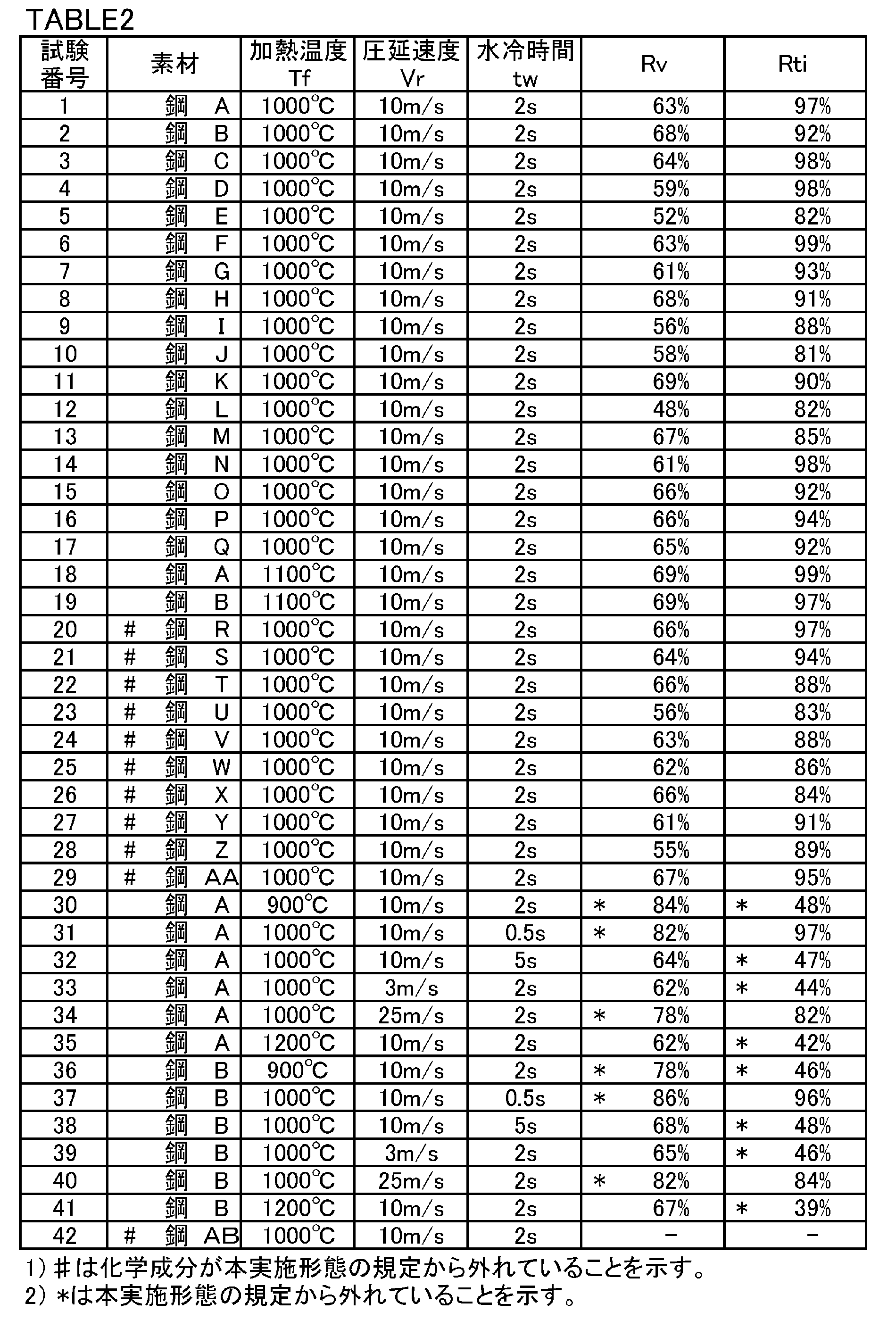
上述の測定方法に基づいて、各試験番号のVm(%)、Vp(%)、Tim(%)及びTip(%)を求めた。さらに、式(2)及び式(3)を用いて、V比率Rv及びTi比率Rtiを求めた。得られたV比率Rv及びTi比率Rtiを表2に示す。
試験番号1~41の丸棒の各々から複数の小型丸棒試験片と複数の大型丸棒試験片とを採取した。小型丸棒試験片の直径は22mmであり、長さは50mmであった。小型丸棒試験片の中心軸は、対応する35mmの直径を有する試験番号の丸棒の中心軸と一致した。大型丸棒試験片の直径は32mmであり、長さは50mmであった。大型丸棒試験片の中心軸は、対応する35mmの直径を有する試験番号の丸棒の中心軸と一致した。
試験番号42の丸棒から、複数の大型丸棒試験片を採取した。大型丸棒試験片を加熱して、1250℃で5分間保持した。その後、前方押出加工を実施して、20mmの直径を有する丸棒を製造した。以下、試験番号42の模擬鍛造品を、「基準品」という。
各試験番号の低温模擬鍛造品、高温模擬鍛造品及び基準品を用いて、ミクロ組織観察試験を実施した。具体的には、各鍛造品(低温模擬鍛造品、高温模擬鍛造品、基準品)の横断面のうち、R/2部を含むサンプルを採取した。サンプルのうち、R/2部を含む横断面に相当する表面(以下、観察面という)を研磨し、ナイタル腐食液で腐食した。腐食後、400倍の光学顕微鏡で、観察面のミクロ組織を観察した。
各鍛造品に対してシャルピー衝撃試験を実施して、クラッキング性を評価した。具体的には、各鍛造品の中央部から、JIS Z 2202(2012)に記載のVノッチ試験片(4号試験片)を採取した。この試験片を用いて、大気中の室温(25℃)でシャルピー衝撃試験を実施し、衝撃値(J/cm2)を求めた。衝撃値が10J/cm2以下である場合、クラッキング性に優れると評価した。
各鍛造品のR/2部から、JIS 14A号試験片を採取した。採取された試験片を用いて、大気中の室温(25℃)で引張試験を実施して、降伏強度YS(MPa)及び引張強度TS(MPa)を求めた。
試験結果を表3に示す。表3中の「ミクロ組織」欄中の「F」は、フェライトが観察されたことを意味する。「P」は、パーライトが観察されたことを意味する。「B」は、ベイナイトが観察されたことを意味する。

Claims (3)
- クラッキングコンロッド用圧延鋼材であって、
質量%で、
C:0.30~0.40%、
Si:0.60~1.00%、
Mn:0.50~1.00%、
P:0.04~0.07%、
S:0.04~0.13%、
Cr:0.10~0.30%、
V:0.05~0.14%、
Ti:0.15%を超えて0.20%以下、
N:0.002~0.020%、
Cu:0~0.40%、
Ni:0~0.30%、
Mo:0~0.10%、
Pb:0~0.30%、
Te:0~0.30%、
Ca:0~0.010%、及び、
Bi:0~0.30%を含有し、残部がFeおよび不純物からなり、式(1)で定義されるfn1が0.65~0.80となる化学組成を有し、
前記クラッキングコンロッド用圧延鋼材中のV含有量に対する、200nm以上の粒子径を有する粗大析出物中のV含有量の比率が70%以下であり、
前記クラッキングコンロッド用圧延鋼材中のTi含有量に対する、前記粗大析出物中のTi含有量の比率が50%以上である、クラッキングコンロッド用圧延鋼材。
fn1=C+Si/10+Mn/5+5Cr/22+(Cu+Ni)/20+Mo/2+33V/20-5S/7・・・式(1)
ここで、式(1)中の元素記号には、対応する元素の含有量(質量%)が代入され、対応する元素が含有されていない場合、「0」が代入される。 - 請求項1に記載のクラッキングコンロッド用圧延鋼材であって、
前記化学組成は、
Cu:0.01~0.40%、
Ni:0.01~0.30%、及び、
Mo:0.01~0.10%からなる群から選択される1種又は2種以上を含有する、クラッキングコンロッド用圧延鋼材。 - 請求項1又は請求項2に記載のクラッキングコンロッド用圧延鋼材であって、
前記化学組成は、
Pb:0.05~0.30%、
Te:0.0003~0.30%、
Ca:0.0003~0.010%、及び、
Bi:0.0003~0.30%からなる群から選択される1種又は2種以上を含有する、クラッキングコンロッド用圧延鋼材。
Priority Applications (6)
| Application Number | Priority Date | Filing Date | Title |
|---|---|---|---|
| CN201480082705.0A CN107075626B (zh) | 2014-10-17 | 2014-10-17 | 涨断连杆用轧制钢材 |
| KR1020177013117A KR101955839B1 (ko) | 2014-10-17 | 2014-10-17 | 크랙킹 커넥팅 로드용 압연 강재 |
| US15/518,035 US10570487B2 (en) | 2014-10-17 | 2014-10-17 | Rolled steel material for fracture splitting connecting rod |
| BR112017007685-3A BR112017007685B1 (pt) | 2014-10-17 | 2014-10-17 | material de aço laminado para haste de conexão de divisão por fratura |
| PCT/JP2014/005274 WO2016059664A1 (ja) | 2014-10-17 | 2014-10-17 | クラッキングコンロッド用圧延鋼材 |
| JP2016553767A JP6298898B2 (ja) | 2014-10-17 | 2014-10-17 | クラッキングコンロッド用圧延鋼材 |
Applications Claiming Priority (1)
| Application Number | Priority Date | Filing Date | Title |
|---|---|---|---|
| PCT/JP2014/005274 WO2016059664A1 (ja) | 2014-10-17 | 2014-10-17 | クラッキングコンロッド用圧延鋼材 |
Publications (1)
| Publication Number | Publication Date |
|---|---|
| WO2016059664A1 true WO2016059664A1 (ja) | 2016-04-21 |
Family
ID=55746236
Family Applications (1)
| Application Number | Title | Priority Date | Filing Date |
|---|---|---|---|
| PCT/JP2014/005274 Ceased WO2016059664A1 (ja) | 2014-10-17 | 2014-10-17 | クラッキングコンロッド用圧延鋼材 |
Country Status (6)
| Country | Link |
|---|---|
| US (1) | US10570487B2 (ja) |
| JP (1) | JP6298898B2 (ja) |
| KR (1) | KR101955839B1 (ja) |
| CN (1) | CN107075626B (ja) |
| BR (1) | BR112017007685B1 (ja) |
| WO (1) | WO2016059664A1 (ja) |
Cited By (2)
| Publication number | Priority date | Publication date | Assignee | Title |
|---|---|---|---|---|
| WO2018155610A1 (ja) * | 2017-02-24 | 2018-08-30 | 新日鐵住金株式会社 | 熱間鍛造用棒鋼 |
| CN109804097A (zh) * | 2016-09-29 | 2019-05-24 | 新日铁住金株式会社 | 热轧钢材及钢部件 |
Families Citing this family (2)
| Publication number | Priority date | Publication date | Assignee | Title |
|---|---|---|---|---|
| CN114645208B (zh) * | 2022-03-23 | 2023-04-25 | 青海西钢特殊钢科技开发有限公司 | 一种采用碲处理的非调质胀断连杆用钢及其生产方法 |
| JP7778098B2 (ja) * | 2023-01-23 | 2025-12-01 | 日本特殊陶業株式会社 | スパークプラグ |
Citations (6)
| Publication number | Priority date | Publication date | Assignee | Title |
|---|---|---|---|---|
| JP2004277817A (ja) * | 2003-03-14 | 2004-10-07 | Daido Steel Co Ltd | 破断分離に適した高強度非調質鋼及びこれを用いた鍛造部品 |
| JP2004277838A (ja) * | 2003-03-18 | 2004-10-07 | Sumitomo Metal Ind Ltd | 非調質鋼 |
| KR20100049264A (ko) * | 2008-11-03 | 2010-05-12 | 현대자동차주식회사 | 커넥팅로드용 고강도 비조질강 |
| JP2010180473A (ja) * | 2009-02-09 | 2010-08-19 | Daido Steel Co Ltd | クラッキングコンロッド及びその製造方法 |
| WO2012164710A1 (ja) * | 2011-06-02 | 2012-12-06 | 新日鐵住金株式会社 | 非調質コネクティングロッド用棒鋼 |
| JP2014025105A (ja) * | 2012-07-26 | 2014-02-06 | Nippon Steel & Sumitomo Metal | コネクティングロッド用鋼及びコネクティングロッド |
Family Cites Families (10)
| Publication number | Priority date | Publication date | Assignee | Title |
|---|---|---|---|---|
| US5135587A (en) | 1991-04-01 | 1992-08-04 | Ford Motor Company | Machinable, strong, but crackable low ductility steel forging |
| JP3988662B2 (ja) * | 2003-03-18 | 2007-10-10 | 住友金属工業株式会社 | 非調質鋼 |
| JP4255861B2 (ja) | 2003-03-18 | 2009-04-15 | 住友金属工業株式会社 | 非調質コネクティングロッド及びその製造方法 |
| EP1605071B1 (en) * | 2003-03-18 | 2008-10-15 | Sumitomo Metal Industries, Ltd. | Non-quenched/tempered connecting rod and method of producing the same |
| JP4997805B2 (ja) * | 2005-03-31 | 2012-08-08 | Jfeスチール株式会社 | 高強度厚鋼板およびその製造方法、ならびに高強度鋼管 |
| US20090277539A1 (en) * | 2005-11-21 | 2009-11-12 | Yuuji Kimura | Steel for Warm Working, Warm Working Method Using the Steel, and Steel Material and Steel Component Obtainable Therefrom |
| JP5380892B2 (ja) * | 2007-05-29 | 2014-01-08 | Jfeスチール株式会社 | 加工性に優れた耐磨耗鋼板およびその製造方法 |
| JP5423191B2 (ja) * | 2009-07-10 | 2014-02-19 | Jfeスチール株式会社 | 高強度鋼板およびその製造方法 |
| JP2011084767A (ja) * | 2009-10-14 | 2011-04-28 | Honda Motor Co Ltd | クラッキングコンロッドの製造方法 |
| US10087510B2 (en) * | 2011-05-19 | 2018-10-02 | Nippon Steel & Sumitomo Metal Corporation | Non-post-heat treated steel and non-post-heat treated steel member |
-
2014
- 2014-10-17 KR KR1020177013117A patent/KR101955839B1/ko active Active
- 2014-10-17 BR BR112017007685-3A patent/BR112017007685B1/pt active IP Right Grant
- 2014-10-17 US US15/518,035 patent/US10570487B2/en active Active
- 2014-10-17 CN CN201480082705.0A patent/CN107075626B/zh active Active
- 2014-10-17 JP JP2016553767A patent/JP6298898B2/ja active Active
- 2014-10-17 WO PCT/JP2014/005274 patent/WO2016059664A1/ja not_active Ceased
Patent Citations (6)
| Publication number | Priority date | Publication date | Assignee | Title |
|---|---|---|---|---|
| JP2004277817A (ja) * | 2003-03-14 | 2004-10-07 | Daido Steel Co Ltd | 破断分離に適した高強度非調質鋼及びこれを用いた鍛造部品 |
| JP2004277838A (ja) * | 2003-03-18 | 2004-10-07 | Sumitomo Metal Ind Ltd | 非調質鋼 |
| KR20100049264A (ko) * | 2008-11-03 | 2010-05-12 | 현대자동차주식회사 | 커넥팅로드용 고강도 비조질강 |
| JP2010180473A (ja) * | 2009-02-09 | 2010-08-19 | Daido Steel Co Ltd | クラッキングコンロッド及びその製造方法 |
| WO2012164710A1 (ja) * | 2011-06-02 | 2012-12-06 | 新日鐵住金株式会社 | 非調質コネクティングロッド用棒鋼 |
| JP2014025105A (ja) * | 2012-07-26 | 2014-02-06 | Nippon Steel & Sumitomo Metal | コネクティングロッド用鋼及びコネクティングロッド |
Cited By (6)
| Publication number | Priority date | Publication date | Assignee | Title |
|---|---|---|---|---|
| CN109804097A (zh) * | 2016-09-29 | 2019-05-24 | 新日铁住金株式会社 | 热轧钢材及钢部件 |
| EP3521473A4 (en) * | 2016-09-29 | 2020-04-08 | Nippon Steel Corporation | HOT ROLLED STEEL AND STEEL PART |
| WO2018155610A1 (ja) * | 2017-02-24 | 2018-08-30 | 新日鐵住金株式会社 | 熱間鍛造用棒鋼 |
| CN110337504A (zh) * | 2017-02-24 | 2019-10-15 | 日本制铁株式会社 | 热锻用棒钢 |
| JPWO2018155610A1 (ja) * | 2017-02-24 | 2019-12-12 | 日本製鉄株式会社 | 熱間鍛造用棒鋼 |
| CN110337504B (zh) * | 2017-02-24 | 2021-06-15 | 日本制铁株式会社 | 热锻用棒钢 |
Also Published As
| Publication number | Publication date |
|---|---|
| BR112017007685B1 (pt) | 2021-05-11 |
| US10570487B2 (en) | 2020-02-25 |
| JPWO2016059664A1 (ja) | 2017-08-17 |
| US20170292178A1 (en) | 2017-10-12 |
| BR112017007685A2 (pt) | 2017-12-19 |
| KR101955839B1 (ko) | 2019-03-07 |
| CN107075626B (zh) | 2018-09-25 |
| JP6298898B2 (ja) | 2018-03-20 |
| KR20170068576A (ko) | 2017-06-19 |
| CN107075626A (zh) | 2017-08-18 |
Similar Documents
| Publication | Publication Date | Title |
|---|---|---|
| KR102090196B1 (ko) | 냉간 단조 조질품용 압연 봉선 | |
| JP6673475B2 (ja) | 熱間鍛造用圧延棒鋼 | |
| KR101750643B1 (ko) | 시효 경화성 강 | |
| JP6528898B2 (ja) | 非調質棒鋼 | |
| JP6614393B2 (ja) | 非調質棒鋼 | |
| JP6298898B2 (ja) | クラッキングコンロッド用圧延鋼材 | |
| WO2018061191A1 (ja) | 冷間鍛造用鋼及びその製造方法 | |
| JP6642236B2 (ja) | 冷間鍛造用鋼 | |
| JP7299475B2 (ja) | 冷間鍛造用鋼材 | |
| JP6617852B2 (ja) | 熱間鍛造用棒鋼 | |
| TW201726940A (zh) | 斷裂分離型連桿用鋼、斷裂分離型連桿以及該等之製造方法 | |
| KR101800563B1 (ko) | 고강도 강, 및 상기 고강도 강을 이용한 크랭크축 | |
| JP2019218584A (ja) | ボルト | |
| JP2022130746A (ja) | 非調質鍛造部品および非調質鍛造用鋼 | |
| JP5030695B2 (ja) | 破断分離性に優れる高炭素鋼およびその製造方法 | |
| JP7127999B2 (ja) | 鍛鋼品用鋼、組立型クランク軸用鍛鋼クランクスローおよび鍛鋼ジャーナル | |
| JP2017179475A (ja) | 破断分離型コネクティングロッド用成型部品、及びコネクティングロッド、並びに該コネクティングロッドの製造方法 | |
| JP6766531B2 (ja) | 冷間鍛造用鋼およびその製造方法 | |
| KR20150110804A (ko) | 시효 경화성 강 | |
| JP2021017618A (ja) | 冷間鍛造用鋼材 | |
| JP5302704B2 (ja) | 冷間加工用の機械構造用鋼およびその製造方法ならびに機械構造用部品 |
Legal Events
| Date | Code | Title | Description |
|---|---|---|---|
| 121 | Ep: the epo has been informed by wipo that ep was designated in this application |
Ref document number: 14904137 Country of ref document: EP Kind code of ref document: A1 |
|
| ENP | Entry into the national phase |
Ref document number: 2016553767 Country of ref document: JP Kind code of ref document: A |
|
| WWE | Wipo information: entry into national phase |
Ref document number: 15518035 Country of ref document: US |
|
| NENP | Non-entry into the national phase |
Ref country code: DE |
|
| REG | Reference to national code |
Ref country code: BR Ref legal event code: B01A Ref document number: 112017007685 Country of ref document: BR |
|
| ENP | Entry into the national phase |
Ref document number: 20177013117 Country of ref document: KR Kind code of ref document: A |
|
| 122 | Ep: pct application non-entry in european phase |
Ref document number: 14904137 Country of ref document: EP Kind code of ref document: A1 |
|
| ENP | Entry into the national phase |
Ref document number: 112017007685 Country of ref document: BR Kind code of ref document: A2 Effective date: 20170413 |