WO2016043216A1 - 容器及びこれを備えた非接触電力伝送システム - Google Patents
容器及びこれを備えた非接触電力伝送システム Download PDFInfo
- Publication number
- WO2016043216A1 WO2016043216A1 PCT/JP2015/076275 JP2015076275W WO2016043216A1 WO 2016043216 A1 WO2016043216 A1 WO 2016043216A1 JP 2015076275 W JP2015076275 W JP 2015076275W WO 2016043216 A1 WO2016043216 A1 WO 2016043216A1
- Authority
- WO
- WIPO (PCT)
- Prior art keywords
- container
- power
- coil
- receiving coil
- transmission system
- Prior art date
- Legal status (The legal status is an assumption and is not a legal conclusion. Google has not performed a legal analysis and makes no representation as to the accuracy of the status listed.)
- Ceased
Links
Images




Classifications
-
- C—CHEMISTRY; METALLURGY
- C12—BIOCHEMISTRY; BEER; SPIRITS; WINE; VINEGAR; MICROBIOLOGY; ENZYMOLOGY; MUTATION OR GENETIC ENGINEERING
- C12M—APPARATUS FOR ENZYMOLOGY OR MICROBIOLOGY; APPARATUS FOR CULTURING MICROORGANISMS FOR PRODUCING BIOMASS, FOR GROWING CELLS OR FOR OBTAINING FERMENTATION OR METABOLIC PRODUCTS, i.e. BIOREACTORS OR FERMENTERS
- C12M1/00—Apparatus for enzymology or microbiology
- C12M1/22—Petri dishes
-
- H—ELECTRICITY
- H02—GENERATION; CONVERSION OR DISTRIBUTION OF ELECTRIC POWER
- H02J—ELECTRIC POWER NETWORKS; CIRCUIT ARRANGEMENTS OR SYSTEMS FOR SUPPLYING OR DISTRIBUTING ELECTRIC POWER; SYSTEMS FOR STORING ELECTRIC ENERGY
- H02J50/00—Circuit arrangements or systems for wireless supply or distribution of electric power
- H02J50/005—Mechanical details of housing or structure aiming to accommodate the power transfer means, e.g. mechanical integration of coils, antennas or transducers into emitting or receiving devices
Definitions
- the present invention relates to a container capable of contactless power transmission and a contactless power transmission system including the same.
- the storage described in Patent Document 1 is provided in a storage room and has a wireless sensor having a detection function such as temperature, an antenna that communicates with the wireless sensor, and information that is sensed by the wireless sensor and received via the antenna. And an information reading device for reading the information and a control means for acquiring the information read by the information reading device and controlling the storage room.
- a wireless sensor having a detection function such as temperature
- an antenna that communicates with the wireless sensor
- an information reading device for reading the information
- a control means for acquiring the information read by the information reading device and controlling the storage room.
- the non-contact power transmission system described in Patent Document 2 includes a power transmission device having a power transmission coil, and a power reception device having a power reception coil and a magnetic flux collecting coil, and the power reception coil using a magnetic flux generated by passing a current through the power transmission coil as a medium. Transmit power to
- the installation location of the power receiving coil and the magnetic flux collecting coil is not limited, and a space for containing a substance is not provided inside. Further, the power receiving device is not made of a material that transmits light. For this reason, even if a space for containing a substance is formed in the power receiving device, it is difficult to observe the inside unless the power receiving device is opened and brought into contact with the outside air.
- an object of the present invention is to provide a container and a non-contact power transmission system capable of observing a substance housed inside without removing a lid. Moreover, it aims at providing the container and non-contact electric power transmission system which can detect environments, such as temperature and humidity, for every container arrange
- an object of the present invention is to provide a container and a non-contact power transmission system that can detect the environment of each container regardless of the accommodation form in the storage.
- the container of the present invention is a container provided with a dish body that can be seen through inside, and a lid part that can see through the inside that covers the top of the dish body,
- a power receiving coil is provided on the peripheral edge or side surface of the upper surface of the lid portion, or the side surface of the dish body, Power is supplied to the power receiving coil by energizing a power feeding coil provided in non-contact with the power receiving coil outside the container.
- the power receiving coil is preferably a conductive ink printing pattern, a flexible printed circuit board, or a conductive pattern formed by thin film formation or surface treatment.
- the receiving coil of a desired shape can be formed at a desired position at a low cost.
- control circuit is preferably disposed on the peripheral edge or side surface of the upper surface of the lid portion or on the side surface of the dish body, and the control circuit is preferably operated by the electric power supplied to the power receiving coil. This makes it possible to manage the environment for each container.
- an antenna is disposed on the peripheral edge or side surface of the upper surface of the lid part or the side surface of the dish body, and the antenna transmits a signal to the outside of the container by the power supplied to the power receiving coil. It is preferable to do.
- an environmental sensor is disposed on the peripheral edge or side surface of the upper surface of the lid portion, or on the side surface of the dish body, and the environmental sensor is preferably operated by electric power supplied to the power receiving coil. This makes it possible to manage the environment for each container.
- a temperature / humidity sensor is preferable as the environmental sensor.
- the container is preferably a petri dish for culturing. With the above-described configuration, it can also be applied to culture that requires strict environmental management.
- a non-contact power transmission system of the present invention is characterized by including any one of the above-described containers, and a power feeding device that includes a placement surface on which the container is placed and is provided with a power feeding coil. Thereby, electric power can be supplied for each container.
- the power supply coil is a conductive ink print pattern, a flexible printed circuit board, or a conductive pattern formed by thin film formation or surface treatment formed on the mounting surface. Is preferred. Thereby, the feed coil of a desired shape can be formed at a low cost at a desired position.
- the surface including the feeding coil and the surface including the power receiving coil are parallel. Therefore, it is possible to efficiently supply power from the power feeding coil to the power receiving coil.
- a plurality of containers be stacked in a direction perpendicular to the placement surface.
- the contactless power transmission system of the present invention it is preferable to include a wireless device capable of communicating with an external device.
- the present invention it is possible to provide a container and a non-contact power transmission system that can observe the inside without taking a cover.
- a container and a non-contact power transmission system that can accurately measure temperature, humidity, and the like for each container.
- FIG. It is a top view which shows the structure of the container which concerns on embodiment of this invention. It is a block diagram which shows the structure of the non-contact electric power transmission system which concerns on embodiment of this invention. It is a perspective view which shows the structure of the coil in embodiment of this invention. It is a circuit diagram which shows the relationship of the coil in embodiment of this invention. It is a side view which shows the state which accumulated the container which concerns on embodiment of this invention.
- FIG. 1 is a side view showing a configuration of a container 10 according to the present embodiment, in which (A) shows a state in which a plate body 30 and a lid portion 20 are separated, and (B) shows a state in which the lid portion 20 is attached to the plate body 30. Each loaded state is shown.
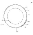
- FIG. 2 is a plan view showing the configuration of the container 10.
- the container 10 includes a cylindrical dish body 30 having a bottom surface and a transparent through-hole, and a cylindrical lid body having a ceiling surface that covers and covers the top of the dish body 30.
- Part 20 The container 10 is, for example, a petri dish for culturing inside, and the dish body 30 and the lid part 20 are preferably formed of glass or a synthetic resin material that allows the inside to be seen through.
- the inside can be seen through means a state in which the state inside the container 10 can be visually observed from the outside, such as transparent or translucent.
- a coil portion 40 is provided on the upper surface 21 of the lid portion 20.
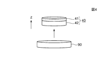
- the coil unit 40 includes a power receiving coil 41 and a load matching coil 42 that are stacked along the height direction Z ⁇ b> 1 of the container 10.
- the coil portion 40 is disposed around the central portion 22 of the upper surface 21 of the lid portion 20.
- the coil part 40 is formed by adhering a spirally wound conducting wire to the lid part 20, and also formed as a conductive ink printing pattern, a flexible printed circuit board, or a conductive pattern formed by thin film formation or surface treatment. You can also
- the power receiving coil 41 is supplied with power by energizing a power supply coil 90 (FIG. 7) provided in a non-contact manner with the power receiving coil 41 outside the container 10.
- a control module 50 and an antenna 60 that are electrically connected to each other by a conducting wire 70 are fixed to the side surface 23 of the lid portion 20 by adhesion.
- the control module 50 is electrically connected to the coil unit 40.
- the control module 50, the antenna 60, and the conductive wire 70 are covered with a non-conductive and non-translucent tape 80.
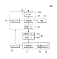
- FIG. 3 is a block diagram showing a configuration of the non-contact power transmission system according to the present embodiment.
- FIG. 4 is a perspective view showing the configuration of the coil in the present embodiment.
- FIG. 5 is a circuit diagram showing the relationship of the coils in the present embodiment.
- the contactless power transmission system includes a container 10 including the coil unit 40 and the control module 50, and a power supply apparatus 100 that supplies power to the container 10 in a contactless manner.
- the control module 50 mounted on the container 10 includes a control circuit 51 and a temperature / humidity sensor 52 as an environmental sensor.
- the control circuit 51, the temperature / humidity sensor 52, and the antenna 60 are operated by the electric power supplied to the power receiving coil 41.
- the temperature / humidity sensor 52 detects the temperature and humidity of the container 10 and outputs them to the control circuit 51.
- the control circuit 51 records the detection result by the temperature / humidity sensor 52 and the ID information set for each container 10 from the antenna 60 to the ID reader 92 through the antenna 93 of the power feeding apparatus 100.
- the antenna 60 modulates and transmits a high-frequency carrier signal with a signal corresponding to the detection result of the temperature / humidity sensor 52 and the ID information.
- the time interval for recording a signal from the antenna 60 to the ID reader 92 and the ID information are stored in advance in the storage unit of the control circuit 51.
- control module 50 is provided with an indicator indicating that the power from the power supply apparatus 100 is being received. Providing this indicator is preferable because it is possible to replace the container 10 that cannot receive power due to a failure of the control module 50 or the like. A light emitting diode etc. are used for an indicator.
- information received by the ID reader 92 is stored in the storage unit of the control unit 91.
- the antenna 93 wireless device
- the relationship between the feeding coil 90, the load matching coil 42 on the container 10 side, and the power receiving coil 41 is as shown in FIG.
- the power supplied from the external power supply 110 is supplied (energized) to the power supply coil 90 as an AC voltage V in having a predetermined waveform (FIG. 5).
- an oscillation circuit is configured by the power feeding coil (L 1 ) 90, the capacitor C 1 and the winding resistance r 1 , and an alternating current having a predetermined frequency (1 MHz or less) is applied to the power feeding coil (L) 90. It is done.
- Capacitor C 1 and winding resistance r 1 are arranged in power supply apparatus 100.
- a resonance circuit is configured by the load matching coil (L 2 ) 42, the resonance capacitor C 2, and the winding resistance r 2 , and the power receiving coil (L 3 ) 41 includes the winding resistance r 2 and the control module. Connected to a load RL such as 50.
- the resonant capacitor C 2 , the winding resistance r 2 , the load R L , and the winding resistance r 3 are arranged in the control module 50.
- the current magnetic field M 12 is induced by an AC signal applied to the power feeding coil 90.
- the current magnetic field M 12 the resonance is generated given the load matching coil (L 2) 42, the induced magnetic field M 23 by the resonance is supplied to the power receiving coil 41, power is supplied to the load R L.
- the impedance is matched by the power feeding coil 90 and the load matching coil 42 and power is supplied to the power receiving coil 41, power corresponding to the power supplied to the power feeding coil 90 can be efficiently transmitted to the power receiving coil 41. That is, by using the load matching coil 42, it is possible to optimize the load characteristics. In particular, when power is supplied to the plurality of power receiving coils 41 with one power supply coil 90, mutual interference does not occur. The overall Q value of the plurality of power receiving coils 41 can be increased while suppressing the Q value to an extent.
- FIG. 6 is a side view showing a state in which the container 10 according to the present embodiment is stacked on the power supply apparatus 100.
- FIG. 7 is a side view showing a state where the container 10 according to the present embodiment is placed on the power supply apparatus 100.
- the container 10 can be stacked by placing a plate body 30 of another container 10 on the lid part 20 on which the coil part 40 is formed.
- the fitting part which mutually fits is provided in the upper part of the cover part 20 and the lower part of the plate main body 30, the position of the piled container 10 in the plane direction (direction orthogonal to a height direction) will be decided, and all in a plane direction Since the center positions of the containers 10 coincide with each other, it is possible to more reliably supply power and to reduce the possibility of dropping due to misalignment.
- the containers 10 stacked in this way are arranged on the mounting surface 101 of the power supply apparatus 100 shown in FIG. Accordingly, the container 10 is stacked in the direction D1 perpendicular to the placement surface 101.
- the feeding coil 90 is formed by adhering a conductive wire wound in a substantially rectangular shape to the mounting surface 101, and also as a conductive pattern formed by conductive ink printing pattern, flexible printed circuit board, or thin film formation or surface treatment. It can also be formed.
- the surface including the feeding coil 90 and the surface including the power receiving coil 41 are parallel.
- the container 10 may be laid flat without being stacked.
- the power supply device 100 and the container 10 arranged on the power supply device 100 configured as described above constitute a non-contact power transmission system.
- the Q value can be suppressed to a level that does not cause mutual interference for each container. This power can be supplied to the receiving coil 41 of each container.
- FIG. 8 is a perspective view showing a state in which the non-contact power transmission system according to the present embodiment is arranged in the storage 120.
- the power supply device 100 is placed on the upper surface 122 a of the main body 122 of the storage 120, and the container 10 is stacked on the placement surface 101 of the power supply device 100 in a direction D ⁇ b> 1 perpendicular to the placement surface 101.
- a lid 121 is placed on the main body 122 so as to surround the container 10 and the power supply apparatus 100.
- the main body 122 is provided with a temperature controller (not shown), and the temperature in the space surrounded by the lid 121 and the main body 122 can be adjusted.
- the temperature / humidity is detected by the temperature / humidity sensor 52 and stored in the storage unit of the control circuit 51.
- the detection result by the temperature / humidity sensor 52 is transmitted to the power feeding apparatus 100 together with the ID information for each container 10, stored in the storage unit of the control unit 91, and transmitted to the outside by the antenna 93.
- the external device that has received the data transmitted from the antenna 93 can check the temperature and humidity for each container 10.
- the power receiving coil 41 is disposed at a position avoiding the central portion 22 of the upper surface 21 of the lid portion 20 through which the inside can be seen, the container 10 can be viewed from above even when the lid portion 20 is placed on the plate body 30. Can be observed inside. Therefore, since the internal environment is not changed by opening the container 10, a more preferable culture environment can be provided.
- the power receiving coil 41, the load matching coil 42, and the power feeding coil 90 with a conductive ink printing pattern, a flexible printed circuit board, or a conductive pattern formed by thin film formation or surface treatment. Can be formed accurately and inexpensively.
- the coil portion 40 may be provided on the side surface of the lid portion 20 or the side surface of the dish body 30 in addition to the peripheral edge portion of the upper surface 21 of the lid portion 20. Further, the control module 50, the antenna 60, and the conductive wire 70 may be disposed on the peripheral portion of the upper surface 21 of the lid portion 20 or the side surface of the dish body 30 in addition to the side surface of the lid portion 20. With these configurations, the inside of the container 10 can be observed from above or below even when the lid 20 is placed on the dish body 30.
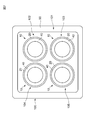
- the four areas 102, 103, 104, and 105 are arranged on the placement surface 101, but the number and arrangement of the areas in which the containers 10 are arranged are not limited to this.
- the container and the non-contact power transmission system according to the present invention are useful in applications where strict environmental management is required and when there is a restriction on the arrangement space of the container.
Landscapes
- Engineering & Computer Science (AREA)
- Health & Medical Sciences (AREA)
- Life Sciences & Earth Sciences (AREA)
- Chemical & Material Sciences (AREA)
- Bioinformatics & Cheminformatics (AREA)
- Wood Science & Technology (AREA)
- Computer Networks & Wireless Communication (AREA)
- Power Engineering (AREA)
- Biotechnology (AREA)
- Organic Chemistry (AREA)
- Zoology (AREA)
- Microbiology (AREA)
- Sustainable Development (AREA)
- Biomedical Technology (AREA)
- Biochemistry (AREA)
- General Engineering & Computer Science (AREA)
- General Health & Medical Sciences (AREA)
- Genetics & Genomics (AREA)
- Medicinal Chemistry (AREA)
- Apparatus Associated With Microorganisms And Enzymes (AREA)
- Charge And Discharge Circuits For Batteries Or The Like (AREA)
Abstract
【課題】蓋部を取ることなく内部に収容した物質を観察することのできる容器及び非接触電力伝送システムを提供する。 【解決手段】内部を透視可能な皿本体と、皿本体の上部を密閉して覆う内部を透視可能な円筒形の蓋部とを備える容器であって、蓋部の上面の周縁部若しくは側面、又は皿本体の側面に受電コイルが設けられ、容器の外部において受電コイルと非接触に設けた給電コイルに通電することにより、受電コイルに給電する。受電コイルは、導電性インクの印刷パターン、フレキシブルプリント基板、又は、薄膜形成若しくは表面処理によって形成された導電性パターンである。
Description
本発明は、非接触電力伝送が可能な容器、及び、これを備えた非接触電力伝送システムに関する。
特許文献1に記載の保存庫は、貯蔵室内に設けられ、温度等の検知機能を持つ無線センサと、この無線センサと通信を行うアンテナと、無線センサによりセンシングされ、アンテナを介して受信した情報を読み取る情報読取装置と、この情報読取装置が読み取った情報を取得し貯蔵室制御を行う制御手段とを備える。この構成により、配線を考慮することなく、任意の箇所にセンサを配置することが可能となるため、貯蔵室内の任意の箇所の情報を取得することが可能となる。
特許文献2に記載の非接触電力伝送システムは、送電コイルを有する送電装置と、受電コイル及び集磁束コイルを有する受電装置とを備え、送電コイルに電流を流して発生した磁束を媒介として受電コイルに電力を伝送する。
特許文献1に記載の保存庫では、冷蔵庫本体及び第一の冷蔵室のいずれも、その構造及び材質上、扉をあけることなく内部を観察することはできないため、観察のたびに保管物が外気に触れ、温湿度が変化してしまう問題があった。このため、培養等のように、容器をあけることなく内部を観察する必要がある用途で使用することは困難であった。
特許文献2に記載の非接触電力伝送システムの受電装置では、受電コイル及び集磁束コイルの設置場所を限定しておらず、また、内部に物質を収容する空間は設けられていない。さらに、受電装置は光を透過する材質で構成されていない。このため、受電装置内に物質を収容する空間を形成したとしても、受電装置を開いて外気に触れさせる状態にしなければ内部を観察することは困難である。
また、特許文献1に記載の保存庫では、貯蔵室の温度等は検知できるものの、貯蔵室内に収容する容器ごとの温度・湿度までは測定できなかった。このため、容器内の物品の性質上、容器ごとに温度・湿度を厳密に管理する必要がある用途には適しているとは言い難かった。
また、複数の容器を貯蔵室内で積み上げた状態で収容する場合と、複数の容器を平置きにした場合とでは、貯蔵室内の環境に大きな差異が生じるため、特許文献1に記載の保存庫では、容器ごとの温度・湿度等を正確に測定することが困難であった。これに対して、温度・湿度等を正確に測定するために複数の容器を貯蔵室内に平置きすると、貯蔵室の床面積を大きくすることが必要となるため、保存庫が大型化してしまうという問題があった。
そこで、本発明は、蓋部を取ることなく内部に収容した物質を観察することのできる、容器及び非接触電力伝送システムを提供することを目的としている。また、貯蔵庫内の任意の箇所に配置した容器ごとの温度・湿度等の環境を検知することのできる容器及び非接触電力伝送システムを提供することを目的としている。
さらにまた、本発明は、貯蔵庫内での収容形態に拘わらずに容器ごとの環境を検知することのできる容器及び非接触電力伝送システムを提供することを目的としている。
上記課題を解決するために、本発明の容器は、内部を透視可能な皿本体と、前記皿本体の上部を覆う内部を透視可能な蓋部とを備える容器であって、
前記蓋部の上面の周縁部若しくは側面、又は前記皿本体の側面に受電コイルが設けられ、
前記容器の外部において前記受電コイルと非接触に設けた給電コイルに通電することにより、前記受電コイルに給電することを特徴としている。
前記蓋部の上面の周縁部若しくは側面、又は前記皿本体の側面に受電コイルが設けられ、
前記容器の外部において前記受電コイルと非接触に設けた給電コイルに通電することにより、前記受電コイルに給電することを特徴としている。
これにより、蓋部をとることなく内部を観察することができるため、観察のたびに容器内の環境を変化させることのない安定した空間を提供することができる。また、容器の配置の自由度を確保しつつ、容器ごとに、温度・湿度等の環境の検知・管理を正確かつ確実に行うことができる。
本発明の容器において、受電コイルは、導電性インクの印刷パターン、フレキシブルプリント基板、又は、薄膜形成若しくは表面処理によって形成された導電性パターンであることが好ましい。
これにより、所望の位置に、所望の形状の受電コイルを安価に形成することできる。
これにより、所望の位置に、所望の形状の受電コイルを安価に形成することできる。
本発明の容器において、蓋部の上面の周縁部若しくは側面、又は皿本体の側面に制御回路が配置されており、制御回路は、受電コイルに供給された電力によって動作することが好ましい。
これにより、容器ごとに環境の管理を行うことが可能となる。
これにより、容器ごとに環境の管理を行うことが可能となる。
本発明の容器において、蓋部の上面の周縁部若しくは側面、又は皿本体の側面にアンテナが配置されており、アンテナは、受電コイルに供給された電力によって、容器の外部に対して信号を送信することが好ましい。
これにより、容器ごとに検知した温度・湿度等の環境データを外部へ送出することができる。
本発明の容器において、蓋部の上面の周縁部若しくは側面、又は皿本体の側面に環境センサが配置されており、環境センサは、受電コイルに供給された電力によって動作することが好ましい。
これにより、容器ごとに環境の管理を行うことが可能となる。
これにより、容器ごとに環境の管理を行うことが可能となる。
本発明の容器において、環境センサとしては温湿度センサが好ましい。本発明の容器において、容器は培養を行うためのシャーレであることが好ましい。
上述の構成により、厳しい環境管理が必要な培養にも適用することができる。
上述の構成により、厳しい環境管理が必要な培養にも適用することができる。
本発明の非接触電力伝送システムは、上述のいずれか1つの容器と、容器が載せられる載置面を備え、給電コイルが設けられた給電装置と、を備えることを特徴としている。
これにより、容器ごとに電力を供給することができるようになる。
これにより、容器ごとに電力を供給することができるようになる。
本発明の非接触電力伝送システムにおいて、給電コイルは、載置面に形成された、導電性インクの印刷パターン、フレキシブルプリント基板、又は、薄膜形成若しくは表面処理によって形成された導電性パターンであることが好ましい。
これにより、所望の位置に、所望の形状の給電コイルを安価に形成することできる。
これにより、所望の位置に、所望の形状の給電コイルを安価に形成することできる。
本発明の非接触電力伝送システムにおいて、給電コイルが含まれる面と、受電コイルが含まれる面とは平行であることが好ましい。
これにより、給電コイルから受電コイルへの給電を効率良く行うことができる。
これにより、給電コイルから受電コイルへの給電を効率良く行うことができる。
本発明の非接触電力伝送システムにおいて、容器は、載置面に垂直な方向に複数積み重ねて配置されることが好ましい。
上述の構成により容器の配置の制約が少ないため、配置空間を広げることなく積み重ねて配置することができる。
本発明の非接触電力伝送システムにおいて、外部機器と通信可能な無線装置を備えることが好ましい。
これにより、容器ごとの環境管理の経過や結果を外部のパソコン、タブレット等に取り込むことができる。
本発明によると、蓋部をとることなく内部を観察することができる、容器及び非接触電力伝送システムを提供することができる。また、容器ごとにワイヤレス給電を行えるようにしたことにより、容器単位で温度・湿度等を正確に測定できる、容器及び非接触電力伝送システムを提供することができる。
以下、本発明の実施形態に係る容器及び非接触電力伝送システムについて図面を参照しつつ詳しく説明する。
図1は、本実施形態に係る容器10の構成を示す側面図であって、(A)は皿本体30と蓋部20を分離した状態を、(B)は皿本体30に蓋部20を載せた状態をそれぞれ示している。図2は、容器10の構成を示す平面図である。
容器10は、図1に示すように、底面を有する内部を透視可能な円筒形の皿本体30と、皿本体30の上部を密閉して覆う天井面を有する内部を透視可能な円筒形の蓋部20とを備える。容器10は、例えば、内部で培養を行うためのシャーレであって、皿本体30及び蓋部20は内部を透視可能なガラスや合成樹脂材料で形成されることが好ましい。本明細書での「内部を透視可能な」とは、透明または半透明など、容器10の内部の状態を外部から目視などで観察可能な状態を意味している。
蓋部20の上面21には、コイル部40が設けられている。コイル部40は、図4に示すように、容器10の高さ方向Z1に沿って積み重ねられた、受電コイル41と負荷整合コイル42とからなる。コイル部40は、蓋部20の上面21の中央部22の周囲に配置される。コイル部40は、螺旋状に巻いた導線を蓋部20に接着して形成するほか、導電性インクの印刷パターン、フレキシブルプリント基板、又は、薄膜形成若しくは表面処理によって形成された導電性パターンとして形成することもできる。受電コイル41は、容器10の外部において受電コイル41と非接触に設けた給電コイル90(図7)に通電することにより、給電される。
図1に示すように、蓋部20の側面23には、導線70によって互いに電気的に接続された、制御モジュール50とアンテナ60が、接着により固定されている。制御モジュール50はコイル部40に電気的に接続されている。制御モジュール50、アンテナ60,及び導線70は、非導電性で非透光性のテープ80によって覆われている。
図3は、本実施形態に係る非接触電力伝送システムの構成を示すブロック図である。図4は、本実施形態におけるコイルの構成を示す斜視図である。図5は、本実施形態におけるコイルの関係を示す回路図である。
本実施形態に係る非接触電力伝送システムは、前記コイル部40ならびに制御モジュール50を備えた容器10と、この容器10に非接触で給電する給電装置100とを有している。
図3に示すように、容器10に搭載された制御モジュール50は、制御回路51と、環境センサとしての温湿度センサ52とを備える。制御回路51、温湿度センサ52、及びアンテナ60は、受電コイル41に供給された電力によって動作する。温湿度センサ52は、容器10の温度及び湿度を検知して制御回路51へ出力する。制御回路51は、温湿度センサ52による検知結果と、容器10ごとに設定されたID情報とをアンテナ60から給電装置100のアンテナ93を通してIDリーダ92へ記録される。アンテナ60は、例えば高周波の搬送信号を、温湿度センサ52による検知結果とID情報に対応する信号で変調して送信する。アンテナ60からIDリーダ92へ信号を記録する時間間隔、及び、ID情報は、制御回路51の記憶部に予め保存されている。
また、制御モジュール50に、給電装置100からの電力を受電している状態であることを示すインジケータを設けることが好ましい。このインジケータを設けると、制御モジュール50の故障などにより受電できていない容器10の交換等を行えるため好ましい。インジケータは、発光ダイオードなどを用いる。
給電装置100では、IDリーダ92が受信した情報が制御部91の記憶部に保存される。制御部91に対して、外部機器から、記憶部に保存した情報の取り出し要求があった場合は、アンテナ93(無線装置)によって外部機器へ送信することができる。
給電コイル90と、容器10側の負荷整合コイル42、及び受電コイル41の関係は、図5に示すとおりである。
給電装置100に設けられた制御部91では、外部の電源110から供給された電力を、所定の波形の交流電圧Vin(図5)として給電コイル90に供給(通電)する。給電装置100では、給電コイル(L1)90とコンデンサC1ならびに巻線抵抗r1で発振回路が構成されており、給電コイル(L)90に所定の周波数(1MHz以下)の交番電流が与えられる。コンデンサC1及び巻線抵抗r1は給電装置100内に配置されている。
容器10側では、負荷整合コイル(L2)42と共振コンデンサC2ならびに巻線抵抗r2により共振回路が構成されており、受電コイル(L3)41は巻線抵抗r2と、制御モジュール50などの負荷RLに接続されている。容器10側では、共振コンデンサC2、巻線抵抗r2、負荷RL、及び、巻線抵抗r3は制御モジュール50に配置されている。
この構成では、給電コイル90に与えられる交流信号により電流磁界M12が誘導される。この電流磁界M12は、負荷整合コイル(L2)42に与えられて共振が発生し、この共振による誘導磁界M23が受電コイル41に与えられ、負荷RLに電力が供給される。
給電コイル90、負荷整合コイル42でインピーダンスが整合されて受電コイル41に給電されるため、給電コイル90に供給した電力に応じた電力を効率良く受電コイル41に伝達することができる。すなわち、負荷整合コイル42を用いたことにより、負荷特性を最適なものにすることができ、特に、1つの給電コイル90で複数の受電コイル41に電力を供給する場合に、相互干渉を生じない程度のQ値に抑えつつ、複数の受電コイル41の全体のQ値を高めることができる。
図6は、本実施形態に係る容器10を給電装置100の上に積み重ねた状態を示す側面図である。図7は、本実施形態に係る容器10を給電装置100上に置いた状態を示す側面図である。
容器10は、図6に示すように、コイル部40を形成した蓋部20上に、別の容器10の皿本体30を載せることによって積み上げることができる。ここで、蓋部20の上部と皿本体30の下部に互いに嵌め合う嵌合部を設けると、積み上げた容器10の平面方向(高さ方向に直交する方向)の位置が決まり、平面方向における全ての容器10の中心位置が一致するため、電力の供給がより確実になり、また位置ずれによる落下の可能性が小さくなる。このように積み上げられた容器10は、図7に示す給電装置100の載置面101上に配置される。これにより、容器10は、載置面101に垂直な方向D1に積み上げられる。
平面視略四角形の載置面101には、容器10を配置する4つの領域102、103、104、105(図6、図7)が設けられ、これらの領域を囲むように、周縁部に給電コイル90が形成されている。給電コイル90は略矩形状に巻いた導線を載置面101に接着して形成するほか、導電性インクの印刷パターン、フレキシブルプリント基板、又は、薄膜形成若しくは表面処理によって形成された導電性パターンとして形成することもできる。ここで、給電コイル90が含まれる面と、受電コイル41が含まれる面とは平行となる。なお、容器10は、積み上げずに平置きしてもよい。
以上のような構成の、給電装置100と給電装置100上に配置された容器10は非接触電力伝送システムを構成する。本実施形態の非接触電力伝送システムにおいては、負荷整合コイル42を設けることにより、容器10を積み上げても、各容器について相互干渉が生じない程度のQ値に抑えることができるため、適切な大きさの電力をそれぞれの容器の受電コイル41に供給することができる。
図8は、本実施形態に係る非接触電力伝送システムを保存庫120内に配置した状態を示す斜視図である。保存庫120の本体部122の上面122aには給電装置100が載置され、給電装置100の載置面101上には、載置面101に垂直な方向D1に容器10が積み上げられている。本体部122上には、容器10及び給電装置100を囲むように、蓋部121が載せられる。本体部122には、温度コントローラ(不図示)が設けられており、蓋部121と本体部122で囲まれる空間内の温度を調節可能である。
保存庫120に保存されている容器10においては、温湿度センサ52によって温度・湿度が検知され、制御回路51の記憶部に保存されている。また、温湿度センサ52による検知結果は、容器10ごとのID情報とともに給電装置100に送信され、制御部91の記憶部に保存されるとともに、アンテナ93によって外部に送信される。アンテナ93から送信されたデータを受信した外部機器は、容器10ごとに温度・湿度をチェックすることが可能である。
以上のように構成されたことから、上記実施形態によれば、次の効果を奏する。
(1)受電コイル41を、内部を透視可能な蓋部20の上面21の中央部22を避けた位置に配置しているため、蓋部20を皿本体30に載せた状態でも上方から容器10の内部を観察することができる。したがって、容器10を開けることによって内部の環境を変えることがないため、より好ましい培養環境を提供することができる。
(1)受電コイル41を、内部を透視可能な蓋部20の上面21の中央部22を避けた位置に配置しているため、蓋部20を皿本体30に載せた状態でも上方から容器10の内部を観察することができる。したがって、容器10を開けることによって内部の環境を変えることがないため、より好ましい培養環境を提供することができる。
(2)それぞれの容器10に受電コイル41を設け、容器10の外部に給電コイル90を配置した構成により、給電コイル90と非接触で受電コイル41に電力を供給することが可能となるため、容器10の配置の自由度を確保しつつ、容器10ごとの温度・湿度管理を正確に行うことができる。
(3)受電コイル41、負荷整合コイル42、及び給電コイル90を、導電性インクの印刷パターン、フレキシブルプリント基板、又は、薄膜形成若しくは表面処理によって形成された導電性パターンで形成することにより、所望の形状を正確かつ安価に形成することできる。
(4)制御モジュール50、アンテナ60、及び導線70を蓋部20の側面に配置することにより、蓋部20を皿本体30に載せた状態でも上方から容器10の内部を観察することができる。
(5)給電コイル90が含まれる面(載置面101に平行な面)と、受電コイル41が含まれる面とを平行にすることにより、給電コイル90から受電コイル41への給電を効率良く行うことができる。
さらに、蓋部20の上面21にコイル部40が配置された容器10を、載置面101に垂直な方向に積み上げることにより、給電コイル90からそれぞれの受電コイル41への給電を効率良く行うことができる。
さらに、蓋部20の上面21にコイル部40が配置された容器10を、載置面101に垂直な方向に積み上げることにより、給電コイル90からそれぞれの受電コイル41への給電を効率良く行うことができる。
(6)負荷整合コイル42を用いることにより、それぞれの容器10の受電コイル41について、相互干渉を生じない程度のQ値に抑えつつ、複数の受電コイル41の全体のQ値を高めることができる。
以下に変形例について説明する。
コイル部40は、蓋部20の上面21の周縁部のほか、蓋部20の側面、又は、皿本体30の側面に設けてもよい。また、制御モジュール50、アンテナ60、及び導線70は、蓋部20の側面のほか、蓋部20の上面21の周縁部、又は皿本体30の側面に配置してもよい。これらの構成により、蓋部20を皿本体30に載せた状態でも、上方又は下方から容器10の内部を観察することができる。
コイル部40は、蓋部20の上面21の周縁部のほか、蓋部20の側面、又は、皿本体30の側面に設けてもよい。また、制御モジュール50、アンテナ60、及び導線70は、蓋部20の側面のほか、蓋部20の上面21の周縁部、又は皿本体30の側面に配置してもよい。これらの構成により、蓋部20を皿本体30に載せた状態でも、上方又は下方から容器10の内部を観察することができる。
図7においては、載置面101上に4つの領域102、103、104、105を配置したが、容器10を配置する領域の数や配置はこれに限定されない。
本発明について上記実施形態を参照しつつ説明したが、本発明は上記実施形態に限定されるものではなく、改良の目的または本発明の思想の範囲内において改良または変更が可能である。
以上のように、本発明に係る容器及び非接触電力伝送システムは、厳密な環境管理が必要な用途や、容器の配置スペースに制約がある場合に有用である。
10 容器
20 蓋部
22 中央部
30 皿本体
40 コイル部
41 受電コイル
42 負荷整合コイル
50 制御モジュール
51 制御回路
52 温湿度センサ
60 アンテナ
90 給電コイル
100 給電装置
101 載置面
120 保存庫
20 蓋部
22 中央部
30 皿本体
40 コイル部
41 受電コイル
42 負荷整合コイル
50 制御モジュール
51 制御回路
52 温湿度センサ
60 アンテナ
90 給電コイル
100 給電装置
101 載置面
120 保存庫
Claims (12)
- 内部を透視可能な皿本体と、前記皿本体の上部を覆う内部を透視可能な蓋部とを備える容器であって、
前記蓋部の上面の周縁部若しくは側面、又は前記皿本体の側面に受電コイルが設けられ、
前記容器の外部において前記受電コイルと非接触に設けた給電コイルに通電することにより、前記受電コイルに給電することを特徴とする容器。 - 前記受電コイルは、導電性インクの印刷パターン、フレキシブルプリント基板、又は、薄膜形成若しくは表面処理によって形成された導電性パターンである
ことを特徴とする請求項1に記載の容器。 - 前記蓋部の上面の周縁部若しくは側面、又は前記皿本体の側面に制御回路が配置されており、
前記制御回路は、前記受電コイルに供給された電力によって動作する
ことを特徴とする請求項1または2に記載の容器。 - 前記蓋部の上面の周縁部若しくは側面、又は前記皿本体の側面にアンテナが配置されており、
前記アンテナは、前記受電コイルに供給された電力によって、前記容器の外部に対して信号を送信する
ことを特徴とする請求項1または2に記載の容器。 - 前記蓋部の上面の周縁部若しくは側面、又は前記皿本体の側面に環境センサ が配置されており、
前記環境センサは、前記受電コイルに供給された電力によって動作する
ことを特徴とする請求項1または2に記載の容器。 - 前記環境センサは温湿度センサである
ことを特徴とする請求項5に記載の容器。 - 前記容器は培養を行うためのシャーレである
ことを特徴とする請求項1から請求項6のいずれか1項に記載の容器。 - 請求項1から請求項7のいずれか1項に記載の容器と、
前記容器が載せられる載置面を備え、前記給電コイルが設けられた給電装置と、
を備えることを特徴とする非接触電力伝送システム。 - 前記給電コイルは、前記載置面に形成された、導電性インクの印刷パターン、フレキシブルプリント基板、又は、薄膜形成若しくは表面処理によって形成された導電性パターンである
ことを特徴とする請求項8に記載の非接触電力伝送システム。 - 前記給電コイルが含まれる面と、前記受電コイルが含まれる面とは平行である
ことを特徴とする請求項9に記載の非接触電力伝送システム。 - 前記容器は、前記載置面に垂直な方向に複数積み重ねて配置される
ことを特徴とする請求項8に記載の非接触電力伝送システム。 - 外部機器と通信可能な無線装置を備えた
ことを特徴とする請求項8に記載の非接触電力伝送システム。
Applications Claiming Priority (2)
| Application Number | Priority Date | Filing Date | Title |
|---|---|---|---|
| JP2014189459A JP6706444B2 (ja) | 2014-09-17 | 2014-09-17 | 容器及びこれを備えた非接触電力伝送システム |
| JP2014-189459 | 2014-09-17 |
Publications (1)
| Publication Number | Publication Date |
|---|---|
| WO2016043216A1 true WO2016043216A1 (ja) | 2016-03-24 |
Family
ID=55533252
Family Applications (1)
| Application Number | Title | Priority Date | Filing Date |
|---|---|---|---|
| PCT/JP2015/076275 Ceased WO2016043216A1 (ja) | 2014-09-17 | 2015-09-16 | 容器及びこれを備えた非接触電力伝送システム |
Country Status (2)
| Country | Link |
|---|---|
| JP (1) | JP6706444B2 (ja) |
| WO (1) | WO2016043216A1 (ja) |
Cited By (2)
| Publication number | Priority date | Publication date | Assignee | Title |
|---|---|---|---|---|
| US20200032192A1 (en) * | 2018-01-03 | 2020-01-30 | Boe Technology Group Co., Ltd. | Culture device and cell culture method using same |
| JPWO2020183948A1 (ja) * | 2019-03-12 | 2020-09-17 |
Families Citing this family (3)
| Publication number | Priority date | Publication date | Assignee | Title |
|---|---|---|---|---|
| CN108701265A (zh) * | 2016-03-14 | 2018-10-23 | 欧姆龙株式会社 | 学习服务提供装置 |
| JP7019492B2 (ja) * | 2018-04-04 | 2022-02-15 | Nittoku株式会社 | 製造装置 |
| JP7168911B2 (ja) * | 2019-01-29 | 2022-11-10 | 株式会社島津製作所 | 撮像環境測定器および撮像環境測定システム |
Citations (8)
| Publication number | Priority date | Publication date | Assignee | Title |
|---|---|---|---|---|
| JP2006214644A (ja) * | 2005-01-07 | 2006-08-17 | Matsushita Electric Ind Co Ltd | 保存庫 |
| JP2007252292A (ja) * | 2006-03-24 | 2007-10-04 | Noritsu Koki Co Ltd | 酵素水生成装置 |
| JP2007304968A (ja) * | 2006-05-12 | 2007-11-22 | Hitachi Plant Technologies Ltd | Rfidアンテナ設置台 |
| JP2009088178A (ja) * | 2007-09-28 | 2009-04-23 | Tsuchiya Co Ltd | 非接触電力伝送用フィルム |
| JP2009284810A (ja) * | 2008-05-29 | 2009-12-10 | Sanyo Electric Co Ltd | インキュベータ |
| JP2010273603A (ja) * | 2009-05-28 | 2010-12-09 | Sanyo Electric Co Ltd | 自動培養装置、作業台及びインキュベータ |
| JP2011187559A (ja) * | 2010-03-05 | 2011-09-22 | Tsuchiya Co Ltd | 非接触電力伝送フィルム |
| JP2012050209A (ja) * | 2010-08-25 | 2012-03-08 | Nec Tokin Corp | 非接触電力伝送システム |
Family Cites Families (5)
| Publication number | Priority date | Publication date | Assignee | Title |
|---|---|---|---|---|
| JP4772549B2 (ja) * | 2006-03-24 | 2011-09-14 | 高砂熱学工業株式会社 | 微生物不活化効果判定装置 |
| JP2011142559A (ja) * | 2010-01-08 | 2011-07-21 | Sony Corp | 給電装置、受電装置、およびワイヤレス給電システム |
| JP2011223739A (ja) * | 2010-04-09 | 2011-11-04 | Sony Corp | 給電装置、受電装置、およびワイヤレス給電システム |
| JP5559665B2 (ja) * | 2010-11-30 | 2014-07-23 | 株式会社日立製作所 | 非接触給電装置のインピーダンス整合方法とそれを用いた非接触給電装置 |
| JP6044865B2 (ja) * | 2012-01-03 | 2016-12-14 | 菊地 秀雄 | 誘導電力伝送システム |
-
2014
- 2014-09-17 JP JP2014189459A patent/JP6706444B2/ja active Active
-
2015
- 2015-09-16 WO PCT/JP2015/076275 patent/WO2016043216A1/ja not_active Ceased
Patent Citations (8)
| Publication number | Priority date | Publication date | Assignee | Title |
|---|---|---|---|---|
| JP2006214644A (ja) * | 2005-01-07 | 2006-08-17 | Matsushita Electric Ind Co Ltd | 保存庫 |
| JP2007252292A (ja) * | 2006-03-24 | 2007-10-04 | Noritsu Koki Co Ltd | 酵素水生成装置 |
| JP2007304968A (ja) * | 2006-05-12 | 2007-11-22 | Hitachi Plant Technologies Ltd | Rfidアンテナ設置台 |
| JP2009088178A (ja) * | 2007-09-28 | 2009-04-23 | Tsuchiya Co Ltd | 非接触電力伝送用フィルム |
| JP2009284810A (ja) * | 2008-05-29 | 2009-12-10 | Sanyo Electric Co Ltd | インキュベータ |
| JP2010273603A (ja) * | 2009-05-28 | 2010-12-09 | Sanyo Electric Co Ltd | 自動培養装置、作業台及びインキュベータ |
| JP2011187559A (ja) * | 2010-03-05 | 2011-09-22 | Tsuchiya Co Ltd | 非接触電力伝送フィルム |
| JP2012050209A (ja) * | 2010-08-25 | 2012-03-08 | Nec Tokin Corp | 非接触電力伝送システム |
Cited By (4)
| Publication number | Priority date | Publication date | Assignee | Title |
|---|---|---|---|---|
| US20200032192A1 (en) * | 2018-01-03 | 2020-01-30 | Boe Technology Group Co., Ltd. | Culture device and cell culture method using same |
| JPWO2020183948A1 (ja) * | 2019-03-12 | 2020-09-17 | ||
| WO2020183948A1 (ja) * | 2019-03-12 | 2020-09-17 | 富士フイルム株式会社 | インキュベータ及びマイクロ流体デバイスの稼働方法 |
| US12325845B2 (en) | 2019-03-12 | 2025-06-10 | Fujifilm Corporation | Incubator and method of operating microfluidic device |
Also Published As
| Publication number | Publication date |
|---|---|
| JP6706444B2 (ja) | 2020-06-10 |
| JP2016059323A (ja) | 2016-04-25 |
Similar Documents
| Publication | Publication Date | Title |
|---|---|---|
| WO2016043216A1 (ja) | 容器及びこれを備えた非接触電力伝送システム | |
| US10368958B2 (en) | Surgical container contents detection system | |
| US20100328044A1 (en) | Inductive power system and method of operation | |
| CN102449874B (zh) | 用于探测无线功率传输系统中的装置的方法和装置 | |
| US6546795B1 (en) | Wireless liquid level sensing system and method | |
| US6392544B1 (en) | Method and apparatus for selectively activating radio frequency identification tags that are in close proximity | |
| TWI526937B (zh) | 銷售點感應系統及其方法 | |
| JP2009010394A5 (ja) | ||
| JP5195263B2 (ja) | 情報伝達媒体管理システム | |
| US10978918B1 (en) | Wireless power devices with capacitive foreign object detection sensors | |
| CN103636098A (zh) | 用于检测、表征以及跟踪感应电力接收器的系统和方法 | |
| EP2362812B1 (en) | Laboratory sample carrier tray and tracking method | |
| EP2994727B1 (en) | A video shooting and loads movement device applicable in a removable manner to the fork of a fork lift or of a lifter | |
| US7772980B2 (en) | Method and systems for localizing objects using capacitively coupled RFIDs | |
| JP2017169365A (ja) | 培養容器用検知ユニット、容器及び非接触電力伝送システム | |
| JP5615908B2 (ja) | 無線電力伝送システムにおいて装置を検出する方法及び装置 | |
| JP6299455B2 (ja) | 自動取引装置 | |
| JP2017169364A (ja) | 給電ユニット及び非接触電力伝送システム | |
| KR20230070996A (ko) | 저전력 방식으로 온도의 주기적 센싱, 저장 및 전송이 가능하고 신선물류박스의 개봉 없이 교체관리 가능한 온도 리더로거, 및 이를 포함하는 신선물류 박스 | |
| US20070102529A1 (en) | Information devices | |
| CN104578337A (zh) | 放置于冰箱间室中的用电设备与冰箱 | |
| US20200156887A1 (en) | Consumable carrier with code reader | |
| JP2024008255A (ja) | 伝送装置 | |
| KR102486924B1 (ko) | 데이터 로거 장치 | |
| EP4446159A1 (en) | Standalone drive over module |
Legal Events
| Date | Code | Title | Description |
|---|---|---|---|
| 121 | Ep: the epo has been informed by wipo that ep was designated in this application |
Ref document number: 15842238 Country of ref document: EP Kind code of ref document: A1 |
|
| NENP | Non-entry into the national phase |
Ref country code: DE |
|
| 122 | Ep: pct application non-entry in european phase |
Ref document number: 15842238 Country of ref document: EP Kind code of ref document: A1 |