WO2016043044A1 - 吸収性物品の製造装置 - Google Patents
吸収性物品の製造装置 Download PDFInfo
- Publication number
- WO2016043044A1 WO2016043044A1 PCT/JP2015/074842 JP2015074842W WO2016043044A1 WO 2016043044 A1 WO2016043044 A1 WO 2016043044A1 JP 2015074842 W JP2015074842 W JP 2015074842W WO 2016043044 A1 WO2016043044 A1 WO 2016043044A1
- Authority
- WO
- WIPO (PCT)
- Prior art keywords
- groove
- absorbent article
- convex
- roll
- tension
- Prior art date
- Legal status (The legal status is an assumption and is not a legal conclusion. Google has not performed a legal analysis and makes no representation as to the accuracy of the status listed.)
- Ceased
Links
Images


Classifications
-
- A—HUMAN NECESSITIES
- A61—MEDICAL OR VETERINARY SCIENCE; HYGIENE
- A61F—FILTERS IMPLANTABLE INTO BLOOD VESSELS; PROSTHESES; DEVICES PROVIDING PATENCY TO, OR PREVENTING COLLAPSING OF, TUBULAR STRUCTURES OF THE BODY, e.g. STENTS; ORTHOPAEDIC, NURSING OR CONTRACEPTIVE DEVICES; FOMENTATION; TREATMENT OR PROTECTION OF EYES OR EARS; BANDAGES, DRESSINGS OR ABSORBENT PADS; FIRST-AID KITS
- A61F13/00—Bandages or dressings; Absorbent pads
- A61F13/15—Absorbent pads, e.g. sanitary towels, swabs or tampons for external or internal application to the body; Supporting or fastening means therefor; Tampon applicators
- A61F13/45—Absorbent pads, e.g. sanitary towels, swabs or tampons for external or internal application to the body; Supporting or fastening means therefor; Tampon applicators characterised by the shape
- A61F13/47—Sanitary towels, incontinence pads or napkins
- A61F13/472—Sanitary towels, incontinence pads or napkins specially adapted for female use
-
- A—HUMAN NECESSITIES
- A61—MEDICAL OR VETERINARY SCIENCE; HYGIENE
- A61F—FILTERS IMPLANTABLE INTO BLOOD VESSELS; PROSTHESES; DEVICES PROVIDING PATENCY TO, OR PREVENTING COLLAPSING OF, TUBULAR STRUCTURES OF THE BODY, e.g. STENTS; ORTHOPAEDIC, NURSING OR CONTRACEPTIVE DEVICES; FOMENTATION; TREATMENT OR PROTECTION OF EYES OR EARS; BANDAGES, DRESSINGS OR ABSORBENT PADS; FIRST-AID KITS
- A61F13/00—Bandages or dressings; Absorbent pads
- A61F13/15—Absorbent pads, e.g. sanitary towels, swabs or tampons for external or internal application to the body; Supporting or fastening means therefor; Tampon applicators
- A61F13/53—Absorbent pads, e.g. sanitary towels, swabs or tampons for external or internal application to the body; Supporting or fastening means therefor; Tampon applicators characterised by the absorbing medium
- A61F13/539—Absorbent pads, e.g. sanitary towels, swabs or tampons for external or internal application to the body; Supporting or fastening means therefor; Tampon applicators characterised by the absorbing medium characterised by the connection of the absorbent layers with each other or with the outer layers
Definitions
- the present invention relates to an apparatus for manufacturing absorbent articles such as sanitary napkins.
- absorbent articles such as sanitary napkins, panty liners, incontinence pads, etc., equipped with a liquid-permeable top sheet, a liquid-impermeable back sheet and a liquid-retaining absorbent interposed between both sheets,
- a pressing groove is formed on the surface on the surface sheet side It is widely done.
- the heatable embossing roll having a protrusion for forming the compressed groove corresponding to the shape of the compressed groove on the peripheral surface and the anvil roll having a smooth surface the surface on the surface sheet side is provided.
- the manufacturing method as described in Patent Documents 1 and 2 wherein the laminate is inserted through the embossing roll side, and the laminated body is partially squeezed between the pressing groove forming projection and the smooth surface of the anvil roll. Is widely practiced.
- the high pressure portion and the low pressure portion or the non-pressed portion are alternately arranged along the direction in which the compressed groove extends.
- the compressed groove of the absorbent article manufactured by the manufacturing method described in Patent Literatures 1 and 2 has a shape in which a portion in the front region in front of the excretion portion facing region is simply curved in a convex shape forward. For this reason, when stress is applied to the inner side in the width direction of the front region during use of the absorbent article, vertical stress may occur in the front region due to the stress. When such vertical warp occurs, the fit is poor and body fluid leaks out.
- This invention relates to the manufacturing apparatus of a vertically long absorbent article provided with the pressing groove which has a high pressing part and a low pressing part formed by compacting a surface sheet and an absorber.
- the compressed groove of the absorbent article at least two convex compressed grooves protruding in a convex shape outward of the absorbent article are juxtaposed in the width direction of the absorbent article, and the adjacent convex compressed parts are compressed. It has a shape in which the space between the grooves is recessed toward the inside of the absorbent article.
- the manufacturing apparatus has a high pressurizing part that forms the high pressing part and a low pressurizing part that forms the low pressing part, and a protrusion for forming the pressing groove forming the pressing groove is a circumferential surface.
- the protruding portion for forming the compressed groove has a protruding portion protruding in a convex shape outward in the roll rotation direction corresponding to each protruding portion groove.
- the embossing roll forms the compressed groove in a region sandwiched between the projections adjacent to each other in the roll axis direction on the surface or in a region surrounded by the projections on the surface.
- a tension suppression unit that suppresses the tension of the surface sheet is provided. The tension suppressing portion is raised from the surface of the embossing roll to a position lower than the low pressure portion of the protrusion for forming the compressed groove.
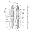
- FIG. 1 is a perspective view of a sanitary napkin, which is an embodiment of an absorbent article manufactured by the absorbent article manufacturing apparatus of the present invention, as viewed from the top sheet side.
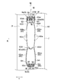
- FIG. 2 is a plan view of the sanitary napkin shown in FIG. 1 as viewed from the top sheet side.
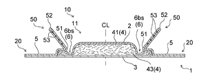
- 3 is a cross-sectional view taken along line III-III in FIG.
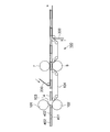
- FIG. 4 is an explanatory view showing an embodiment of the absorbent article manufacturing apparatus of the present invention.
- FIG. 5 is a schematic perspective view showing a pair of emboss rolls and anvil rolls included in the manufacturing apparatus shown in FIG. 4.
- FIG. 6 is a plan view showing protrusions for forming compressed grooves provided on the surface of the embossing roll shown in FIG.
- FIG. 1 is a perspective view of a sanitary napkin, which is an embodiment of an absorbent article manufactured by the absorbent article manufacturing apparatus of the present invention, as viewed from the top sheet side.
- FIG. 2 is a plan view
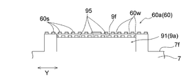
- FIG. 7 is an enlarged view of a protrusion for forming a compressed groove as viewed from the direction VII in FIG. 6.
- 8 is a cross-sectional view taken along line VIII-VIII in FIG.
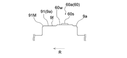
- FIG. 9 is an explanatory view for explaining a state in which the compressed groove is formed by pressing the absorbent body between the embossing roll and the anvil roll through the surface sheet in the manufacturing apparatus shown in FIG. 4.
- Patent Documents 1 and 2 do not describe anything about a manufacturing method or a manufacturing apparatus of an absorbent article including a pressing groove having a shape in which two convexly curved shapes are juxtaposed in the width direction.
- the embossing roll which has the protrusion part for the pressing groove formation corresponding to the shape of the pressing groove of the shape which juxtaposed two convex curved shapes in the width direction is simply used, Since more than one place is squeezed simultaneously in the width direction of the topsheet orthogonal to the transport direction of the laminate, tension to stretch the topsheet is generated. If the surface sheet is squeezed in a state where tension is generated, the surface sheet and the absorber cannot be sufficiently consolidated, and the surface sheet is easily lifted away from the absorber, and such float is absorbed. It contributes to the impediment to performance.
- sanitary napkin 1 (hereinafter also referred to as “napkin 1”), which is an embodiment of an absorbent article manufactured using the manufacturing apparatus of the present invention.
- the napkin 1 is an elongate thing provided with the pressing groove 6 which has the high pressing part 6s formed by compacting the surface sheet 2 and the absorber 4, and the low pressing part 6w.
- the “skin facing surface” is a surface that is disposed on the skin side of the wearer when wearing, among the front and back surfaces of each member such as the surface sheet 2 constituting the napkin 1,
- the “surface” is a surface that is directed to the side opposite to the wearer's skin side (clothing side) when wearing, among the front and back surfaces of each member such as the surface sheet 2 constituting the napkin 1.
- the “front-rear direction” is a direction that coincides with the wearer's front-rear direction when worn, and is also a direction that coincides with the longitudinal direction of the napkin 1.
- the front-rear direction or the longitudinal direction is indicated by “X direction” in each drawing.
- the “Y direction” shown in each figure is a direction orthogonal to the X direction, and is the same direction as the left-right direction or the width direction of the napkin 1. As shown in FIG. 1, the napkin 1 is formed symmetrically with respect to a center line CL extending in the longitudinal direction (X direction) of the napkin 1.
- the napkin 1 has a vertically long absorbent main body 10 that is long in the front-rear direction (X direction), a pair of wing portions 20 and 20, and a pair of rear flap portions 30 and 30. is doing.
- the napkin 1 has an excretory part facing region B in which a wearer's liquid excretion part (vaginal opening or the like) is opposed to the longitudinal direction (X direction), a forward area A in front of the excretion part facing area B, and an excretion part facing region It is divided into a rear region C behind B.
- the napkin 1 is divided into the front area A, the excretory part facing area B, and the rear area C in the front-rear direction (X direction), and a pair of left and right sides of the absorbent main body 10 in the excretory part facing area B are paired.
- Wing portions 20 and 20 are provided, and a pair of rear flap portions 30 and 30 are further provided on the left and right sides of the absorbent main body 10 in the rear region C.
- the napkin 1 includes a liquid permeable top sheet 2 that forms a skin facing surface, a liquid permeable back sheet 3 that forms a non-skin facing surface, and a space between them
- a longitudinally long absorbent main body 10 having an absorbent body 4 arranged in the above is provided.
- the absorptive main body 10 includes a pair of three-dimensional guard forming sheets 5 and 5 joined to both the left and right sides of the topsheet 2. That is, the napkin 1 is provided with a pair of three-dimensional guards 50 and 50 that stand up toward the wearer's skin when worn on both side portions along the longitudinal direction (X direction).
- the surface sheet 2 covers the skin-facing surface of the absorbent body 4 in the napkin 1, and the absorbent body 10 is located at the center in the width direction (Y direction) of the absorbent body 10. It is distribute
- the back sheet 3 covers the entire surface of the non-skin facing surface of the absorbent body 4 in the napkin 1 as shown in FIGS.
- the front and rear ends of the back sheet 3 in the front-rear direction (X direction) extend outward from the front and rear ends of the absorber 4 in the front-rear direction (X direction).
- Both sides along the front-rear direction (X direction) of the back sheet 3 extend outward in the width direction (Y direction) from the left and right sides of the absorber 4.
- the back surface sheet 3 has the outline which corresponds with the outline of the absorptive main body 10 in the front area
- the extended parts of the back surface sheet 3 in the excretion part opposing region B and the rear region C are materials for forming the wing part 20 and the rear flap part 30, respectively.
- the absorbent body 4 is composed of a fiber aggregate made of a fiber material such as pulp fiber, or upper and lower surfaces of an absorbent core in which a super absorbent polymer is held in the fiber aggregate. It is formed by being covered with a core wrap sheet (not shown).
- the absorbent body 4 has a shape that is long in the same direction as the front-rear direction (X direction) of the napkin 1, as shown in FIG. Also has a thick middle-high region. Specifically, the absorbent body 4 has a front middle-high area 41 at the center in the width direction (Y direction) in the area extending from the excretion part facing area B to a part of the rear area C of the napkin 1, and the rear area.
- a rear middle-high region 42 is provided at the center in the width direction (Y direction) of C.
- the absorber 4 has an annular peripheral region 43 that collectively surrounds the front middle-high region 41 and the rear middle-high region 42.
- the napkin 1 has the rear middle-high region 42 in the rear region C in addition to the front middle-high region 41 of the excretory part facing region B.
- the front middle-high region 41 and the rear middle-high region 42 are separated from each other in the longitudinal direction (X direction), and each has a structure that easily fits a predetermined part of the wearer.
- the front middle / high area 41 of the absorbent body 4 exists under the top sheet 2, and thus extends from the excretory part facing area B to a part of the rear area C.
- a front raised portion 11 that protrudes toward the wearer's skin is formed at the center in the width direction of the skin-facing surface in the region, and a rear middle-high region 42 of the absorbent body 4 is provided below the top sheet 2.
- a rear raised portion 12 that protrudes toward the skin side of the wearer is formed at the center in the width direction of the skin facing surface in the rear region C.
- the three-dimensional guard forming sheet 5 constituting the three-dimensional guard 50 is disposed along the front-rear direction (X direction) on each of the left and right side portions of the topsheet 2 as shown in FIGS. Yes.
- the three-dimensional guard forming sheet 5 has a folded portion 51 that is folded outward at a position near the center line CL in the width direction (Y direction) of the absorbent main body 10. It is joined on the topsheet 2 at a portion located outward from the folded portion 51 in the width direction (Y direction).
- the three-dimensional guard forming sheet 5 has an elastic member 53 for forming a three-dimensional guard in the vicinity of the side edge portion 52 that forms the free end of the three-dimensional guard.
- the three-dimensional guard forming sheet 5 When worn, the three-dimensional guard forming sheet 5 is excreted by the contraction force of the elastic member 53. A portion between the folded portion 51 and the side edge portion 52 in the part facing region B stands up toward the wearer's skin side to form the three-dimensional guard 50.
- the pair of wing parts 20, 20 and the pair of rear flap parts 30, 30 are composed of a three-dimensional guard forming sheet 5 and a back sheet 3 extending from both side edges of the absorber 4.
- a wing portion adhesive portion (not shown) for fixing to the non-skin facing surface of the crotch portion of the shorts is provided on the surface composed of the back sheet 3 of each of the pair of wing portions 20.
- attachment part (not shown) for fixing to the surface which consists of the back surface sheet 3 of each of a pair of back flap part 30 to the non-skin opposing surface of shorts is provided.
- top sheet 2 and the back sheet 3 are joined to each other with an adhesive from the peripheral edge of the absorber 4. Then, the top sheet 2, the back sheet 3, and the three-dimensional guard forming sheet 5 follow the contours of the entire periphery of the napkin 1 having the pair of wing portions 20, 20 and the pair of rear flap portions 30, 30, on the entire periphery. They are joined together by heat sealing.
- the napkin 1 includes a pressing groove 6 having a high pressing portion 6s and a low pressing portion 6w formed by compacting the top sheet 2 and the absorbent body 4. That is, in the napkin 1, the surface sheet 2 and the absorber 4 are provided in the skin facing surface with the pressing groove
- the pressing groove 6 has at least two protruding pressing grooves protruding in a convex shape outwardly of the absorbent article, and juxtaposed in the width direction (Y direction) of the absorbent article. It has a shape in which the space is recessed inward.
- the pressing groove 6 of the napkin 1 has the front pressing groove 6a in the front area A, and the rear pressing groove 6c in the back area C, as shown in FIG. .
- the front pressing groove 6a is located in the front area A and extends in the width direction (Y direction)
- the rear pressing groove 6c is located in the rear area C and extends in the width direction (Y direction).
- the compressed groove 6 of the napkin 1 further extends in the longitudinal direction (X direction) on both sides along the longitudinal direction (X direction) in the excretory part facing region B, in addition to the forward compressed groove 6a and the backward compressed groove 6c.
- a laterally compressed groove 6d extending in the width direction (Y direction).
- the horizontal pressing groove 6d is arranged ahead of the rear pressing groove 6c.
- the front pressing groove 6a, the pair of vertical pressing grooves 6bs, 6bs, the pair of vertical pressing grooves 6cs, 6cs, and the rear pressing groove 6c are connected, and the ring extends from the front area A to the rear area C.
- the circumferential groove is formed.
- the front pressing groove 6a has at least two front convex pressing grooves that protrude in a convex shape in the longitudinal direction (X direction) of the napkin 1 and are juxtaposed in the width direction (Y direction) of the napkin 1 and adjacent to each other. It has a shape in which the space between the convex pressing grooves is recessed toward the rear in the longitudinal direction (X direction).
- the forward convex compressed groove of the forward compressed groove 6 a is an arc-shaped right convex compressed groove that protrudes in a diagonally forward right direction on the right side of the center line CL.
- the right convex squeezing groove 6ar and the left convex squeezing groove 6al intersect and are connected while forming a recess 61 that is recessed in a V shape on the rear side on the center line CL side. That is, the right convex squeezing groove 6ar and the left convex squeezing groove 6al are crossed and connected by a recess 61 that is recessed in a V shape on the center line CL side.
- the front pressing groove 6a has the hollow part 61 hollow in the back side, it will not be restricted to the shape mentioned above.
- the front convex squeezing groove of the front squeezing groove 6a has the above-described configuration, it is assumed that stress is applied, for example, from the right outer side to the inner side in the width direction of the front region A during operation while wearing the napkin 1.
- the stress is reduced by the right convex squeezing groove 6ar protruding in a convex shape to the right front, and in particular, vertical scissors are generated in the region surrounded by the right convex squeezing groove 6ar of the front pressing groove 6a. It has become difficult.
- the rear compressed groove 6c has at least two rear convex compressed grooves that protrude in a convex shape rearward in the longitudinal direction (X direction) of the napkin 1, and are arranged adjacent to each other in the width direction (Y direction) of the napkin 1. It has a shape in which the space between the convex compressed grooves is recessed forward in the longitudinal direction (X direction).
- the rear convex pressing groove of the rear pressing groove 6 c is an arc-shaped right convex pressing groove that protrudes in a diagonally rightward rearward direction on the right side of the center line CL.
- the right convex squeezing groove 6cr and the left convex squeezing groove 6cl are crossed and connected to each other while forming a hollow 64 recessed in a V shape on the front side on the center line CL side. That is, the right convex squeezing groove 6cr and the left convex squeezing groove 6cl are crossed and connected by a recessed portion 64 that is recessed in a V shape on the center line CL side.
- the rear compressed groove 6c is not limited to the shape described above as long as it has a recessed portion 64 that is recessed toward the front side.
- the same action as that of the front convex squeezing groove of the front squeezing groove 6a causes an operation while the napkin 1 is being worn. Even if a stress is applied to the inner side in the width direction of the rear region C, vertical wrinkles hardly occur in the region surrounded by the rear compressed groove 6c, and the usability is improved.
- the front pressing groove 6a and each vertical pressing groove 6bs are connected to each other while forming constricted portions 62r and 62l that are narrowed toward the inner side in the width direction (Y direction).
- the pair of vertical pressing grooves 6bs, 6bs are arranged in a region extending from the excretory part facing region B to a part of the rear region C, as shown in FIG.
- the pair of vertical pressing grooves 6bs, 6bs are arranged along both sides of the front middle-high region 41 of the absorber 4, and are formed in an arc shape that is convexly curved outward in the width direction (Y direction).
- the front middle-high area 41 of the absorber 4 is distribute
- the right convex squeezing groove 6ar and the one vertical squeezing groove 6bs constituting the front squeezing groove 6a are connected while forming a right constricted part 62r constricted to the center line CL side.
- the right convex groove 6ar of the front compressed groove 6a and the one vertical compressed groove 6bs are connected by one constricted portion 62r.
- the left convex pressing groove 6al and the other vertical pressing groove 6bs constituting the front pressing groove 6a are connected to each other while forming a left-side constricted portion 62l constricted on the center line CL side.
- the left convex pressing groove 6al of the front pressing groove 6a and the other vertical pressing groove 6bs are connected by the other constricted portion 62l.
- the right side neck portion 62r and the left side neck portion 62l are formed symmetrically with respect to the center line CL.
- Each of the constricted portions 62r and 62l forms a V-shaped bottom constricted toward the center line CL.
- the pair of longitudinal pressing grooves 6cs, 6cs are arranged so as to surround the rear middle / high region 42 of the absorber 4, and are formed in an arc shape that is convexly curved outward in the width direction (Y direction). Is formed.
- one vertical pressing groove 6cs and one vertical pressing groove 6bs intersect and are connected while forming a right intermediate constricted portion 63r that is smoothly constricted on the center line CL side.
- the other vertical pressing groove 6cs and the other vertical pressing groove 6bs intersect and are connected while forming a left intermediate constricted portion 63l that is smoothly constricted on the center line CL side.
- the right intermediate constricted portion 63r and the left intermediate constricted portion 63l are formed symmetrically with respect to the center line CL.
- the right convex groove 6cr and the one vertical compressed groove 6cs constituting the rear compressed groove 6c are smoothly connected while being curved outwardly.
- the left convex pressing groove 6cl and the other vertical pressing groove 6cs constituting the rear pressing groove 6c are smoothly connected to each other while being curved outward.
- the horizontal pressing groove 6 d is formed in a circular arc shape protruding in a backward convex manner in a region between the front middle-high region 41 and the rear middle-high region 4 of the absorber 4. Both end portions of the lateral pressing groove 6d extend to positions near the right intermediate constricted portion 63r and the left intermediate constricted portion 63l.
- the pressing groove 6 has a high pressing portion 6s and a low pressing portion 6w.
- the arrangement pattern of the high-pressure squeezing portion 6s and the low-pressure squeezing portion 6w in the squeezing groove 6 will be described.
- the front squeezing groove 6a constituting the entire circumferential groove of the squeezing groove 6, the pair of vertical pressing grooves 6bs, 6bs, and a pair of As shown in FIG. 2, the vertical pressing grooves 6cs, 6cs, the rear pressing groove 6c, and the lateral pressing grooves 6d of the pressing groove 6 are all provided at the bottom with a plurality of high pressing sections 6s and each height. It has the low pressure part 6w which surrounds the pressing part 6s.
- the high pressing part 6s is intermittently arranged at intervals in the width direction (Y direction), and a pair of vertical pressing grooves.
- the grooves 6bs and 6bs and the pair of vertical pressing grooves 6cs and 6cs they are intermittently arranged with a space in the front-rear direction (X direction).
- the surface sheet 2 and the absorber 4 are squeezed to the back sheet 3 side more strongly than in the low pressing part 6w, and the absorber 4 has the density in the high pressing part 6s in the low pressing part 6w. It is higher than the density.
- the density in the low pressing part 6w is higher than the density in parts other than the pressing groove 6.
- the high pressing part 6s is arrange
- the high pressing parts 6s and the low pressing parts 6w may be alternately arranged in the extending direction.
- the entire circumference of the high-pressure squeezing part 6s is surrounded by the low-pressure squeezing part 6w as in the present embodiment, for example, in the case of the front squeezing groove 6a of the napkin 1, the right convex part squeezed protruding obliquely forward.
- the groove 6ar or the left convex compressed groove 6al does not become too hard, and it is suppressed that the texture during wearing is impaired.
- the high pressing portion 6s is circular, oval, or oval
- the low pressure pressing portion 6w is interposed between the circular high pressing portion and the oval or elliptical high pressing portion. Therefore, it is preferable that the shape is alternately arranged from the viewpoint of achieving both the texture and the shape stability of the groove.
- the material for forming the napkin 1 of the present embodiment will be described.
- various materials conventionally used in absorbent articles such as sanitary napkins can be used without particular limitation.
- the surface sheet 2 a single layer or multilayer nonwoven fabric, an apertured film, or the like can be used.
- the back sheet 3 a liquid hardly permeable or water repellent resin film, a laminate of a resin film and a nonwoven fabric, or the like can be used.
- a stretchable film, a nonwoven fabric, a woven fabric, or a laminated sheet thereof can be used.
- the elastic member 53 for forming a three-dimensional guard can be used without particular limitation as long as it is usually used for absorbent articles such as sanitary napkins.
- natural rubber, polyurethane, polystyrene-polyisoprene copolymer weight can be used.
- a thread-like stretchable material made of a polymer, a polystyrene-polybutadiene copolymer, a polyethylene- ⁇ -olefin copolymer such as ethyl acrylate-ethylene, or the like can be used.
- the adhesive for fixing between the members constituting the napkin 1 it can be used without particular limitation as long as it is usually used for absorbent articles such as sanitary napkins.
- a hot melt adhesive is used.
- hot melt adhesives include blocks such as styrene-isoprene-styrene block copolymer (SIS), styrene-butadiene-styrene block copolymer (SBS), and styrene-ethylene-butylene-styrene copolymer (SEBS).
- SIS styrene-isoprene-styrene block copolymer
- SBS styrene-butadiene-styrene block copolymer
- SEBS styrene-ethylene-butylene-styrene copolymer
- FIG. 4 schematically shows a manufacturing apparatus 100 that is suitably used for manufacturing the napkin 1.
- the manufacturing apparatus 100 includes a high pressing portion 60 s that forms a high pressing portion 6 s and a low pressing portion 60 w that forms a low pressing portion 6 w, and a pressing strip that forms the pressing groove 6.
- a groove-forming projection 60 is provided with an embossing roll 7 provided on the peripheral surface 7 f and an anvil roll 8 disposed opposite to the embossing roll 7.
- One protrusion 60 for forming the compressed groove is provided on the peripheral surface 7f along the roll rotation direction (R direction) of the embossing roll 7, or a plurality of protrusions 60 are provided at equal intervals.
- the pair of embossing rolls 7 and anvil rolls 8 are of a metallic cylindrical shape such as an aluminum alloy or steel, as shown in FIGS.
- the embossing roll 7 has a protrusion 60 for forming a compressed groove that forms the compressed groove 6 of the napkin 1 on the peripheral surface 7f.
- the pair of embossing rolls 7 and the anvil roll 8 are configured to rotate in conjunction with a direction (R direction) indicated by an arrow by transmitting a driving force from a driving means (not shown) to the rotating shaft. .
- the rotational speed of the embossing roll 7 can be controlled by a control unit (not shown) provided in the manufacturing apparatus 100. Further, the pair of embossing rolls 7 and anvil roll 8 can be adjusted in roll temperature, and can be heated when the topsheet 2 and the absorbent body 4 are consolidated.
- the protrusion 60 for forming the compressed groove provided on the peripheral surface 7f of the embossing roll 7 has at least two width directions in the compressed groove 6 formed on the manufactured absorbent article ( It has the convex part protrusion part which protruded convexly to the roll rotation direction (R direction) outward corresponding to each convex part pressing groove groove juxtaposed in the (Y direction).
- “outward in the roll rotation direction (R direction)” means the front in the roll rotation direction (R direction) or the rear in the roll rotation direction (R direction).
- the protrusion 60 for forming the compressed groove is a forward compressed groove protrusion corresponding to the forward compressed groove 6a constituting the compressed groove 6 of the napkin 1 to be manufactured.
- the forward compressed groove projection 60a is located in front of the roll rotation direction (R direction) and extends in the roll axial direction (Y direction), and the rear compressed groove projection 60c is in the roll rotation direction (R direction). ) It is located rearward and extends in the roll axis direction (Y direction).
- the roll rotation direction (R direction) corresponds to the longitudinal direction (X direction) of the manufactured absorbent article
- the roll axis direction (Y direction) is the width direction of the manufactured absorbent article oil. (Y direction).
- the pressing groove forming protrusions 60 are formed as a front pressing groove protrusion 60 a and a rear pressing groove protrusion 60 c.
- a pair of vertical pressing groove projections 60bs, 60bs corresponding to the pair of vertical pressing grooves 6bs, 6bs constituting the pressing groove 6 of the napkin 1 to be manufactured, and the napkin 1 to be manufactured A pair of vertical pressing groove projections 60cs, 60cs corresponding to the pair of vertical pressing grooves 6cs, 6cs constituting the pressing groove 6, and a lateral pressing groove constituting the pressing groove 6 of the napkin 1 to be manufactured.
- the pressing groove forming protrusion 60 is a front pressing groove protrusion 60a, a pair of vertical pressing groove protrusions 60bs, 60bs, and a pair of vertical pressing groove protrusions.
- the protrusions 60cs, 60cs and the rear compressed groove protrusion 60c are connected to form an annular all-round protrusion.
- the protrusion 60 for forming the compressed groove is a front protrusion that protrudes in a convex shape forward in the roll rotation direction (R direction) corresponding to each front protrusion groove 6a of the front compressed groove 6a of the napkin 1 to be manufactured.
- the forward pressing groove protrusion 60 a protrudes forward in the roll rotation direction (R direction) in a convex shape. It has at least two parts, and the front convex protrusions adjacent in the roll axis direction (Y direction) have a shape recessed toward the rear in the roll rotation direction (R direction).
- the forward pressing groove projection 60a includes a right convex pressing groove projection 60ar corresponding to the right convex pressing groove 6ar constituting the forward pressing groove 6a of the napkin 1 to be manufactured. It has the protrusion part 60al for left convex part pressing grooves corresponding to the left convex part pressing groove 6al which comprises the front pressing groove 6a of the napkin 1 manufactured.
- the right convex squeezed groove projection 60ar and the left convex squeeze groove projection 60al are crossed and connected while forming a V-shaped recess on the rear side in the roll rotation direction (R direction). Yes. That is, the right convex squeezing groove projection 60ar and the left convex squeeze groove projection 60al intersect and are connected to each other at a hollow portion that is recessed in a V shape.
- the protrusion part 60 for pressing groove formation is the back which protruded convexly to the roll rotation direction (R direction) back corresponding to each back convex pressing groove of the back pressing groove 6c of the napkin 1 manufactured. It has a convex protrusion.
- the rear pressing groove protrusion 60 c protrudes rearward in the roll rotation direction (R direction) in a convex shape. It has at least two parts, and a shape between the rear convex protrusions adjacent in the roll axis direction (Y direction) is recessed toward the front in the roll rotation direction (R direction).
- channels is the protrusion part 60cr for right protrusion part compression groove
- the right convex squeezing groove projection 60cr and the left convex squeeze groove projection 60cl are crossed and connected while forming a V-shaped depression on the front side in the roll rotation direction (R direction). Yes.
- the right convex squeezing groove projection 60cr and the left convex squeeze groove projection 60cl are crossed and connected to each other by a V-shaped recess.
- the forward compressed groove projections 60a and the vertical compressed groove projections 60bs are connected to each other while forming constricted portions 620r and 620l that are constricted toward the inner side in the roll axis direction (Y direction).
- the right convex squeezing groove 6ar and the one vertical squeezing groove projection 60bs constituting the front squeezing groove projection 60a are constricted on the right side in the roll axis direction (Y direction).
- the parts 620r are connected to form a part 620r.
- the left convex squeezing groove 6al and the other vertical squeezing groove projecting part 60bs constituting the front squeezing groove projecting part 60a include a right constricted part 620l that is constricted inside the roll axial direction (Y direction). It is connected while forming.
- the pair of vertical pressing groove protrusions 60bs, 60bs are formed in an arc shape that is curved outwardly in the roll axis direction (Y direction).
- the pair of vertical pressing groove projections 60cs, 60cs is formed in an arc shape that is curved outwardly in the roll axis direction (Y direction).
- one vertical pressing groove projection 60cs and one vertical pressing groove projection 60bs intersect while forming a right intermediate constriction 630r smoothly wrapped in the roll axis direction (Y direction).
- the other vertical compressed groove projection 60cs and the other vertical compressed groove projection 60bs form a left intermediate constricted portion 630l that is smoothly wrapped inward in the roll axis direction (Y direction). While crossed and connected.
- the right convex groove groove projection 60cr and one vertical pressure groove protrusion 60cs constituting the rear pressure groove groove projection 60c are in the roll axis direction (Y direction). It is smoothly connected while being curved outward. Further, the left convex groove groove protrusion 60cl and the other vertical pressure groove protrusion 60cs constituting the rear compressed groove protrusion 60c are curved outwardly in the roll axis direction (Y direction). While connected smoothly.
- the lateral pressing groove projection 60 d is formed in an arc shape protruding in a convex shape in the roll rotation direction (R direction) rear. Both end portions of the lateral compressed groove projection 60d extend to the positions of the right intermediate constricted portion 630r and the left intermediate constricted portion 630l.
- the protrusion 60 for forming the compressed groove has a high pressure part 60s and a low pressure part 60w.
- the forward compression groove projection part 60a constituting the annularly formed part of the projection part 60 for forming the compression groove
- a pair of vertical compressions Lateral squeezing that constitutes the remaining portions of the projections 60bs, 60bs for the groove
- the projections 60cs, 60cs for the vertical compression groove and the projection 60c for the rear compression groove and the projection 60 for forming the compression groove
- the projection 60 for forming the compression groove As shown in FIG.
- the top surface which is the surface facing the anvil roll 8, surrounds the plurality of high pressure portions 60 s and the high pressure portions 60 s.
- the pressurizing part 60w is formed.
- the high pressing portion 60s is intermittently spaced in the roll axial direction (Y direction) in the forward pressing groove projection 60a, the rear pressing groove projection 60c, and the lateral pressing groove projection 60d.
- the pair of vertical pressing groove projections 60bs, 60bs and the pair of vertical pressing groove projections 60cs, 60cs are intermittently arranged at intervals in the roll rotation direction (R direction). Has been.
- the high pressurization part 60s is raised higher than the low pressurization part 60w from the peripheral surface 7f of the embossing roll 7, and the topsheet 2 and the absorbent body 4 are integrated with high pressure density than the low pressurization part 60w. It is a part which forms the high pressing part 6s.
- the embossing roll 7 is squeezed into a region sandwiched between convex projections adjacent to each other in the roll axis direction (Y direction) on the peripheral surface 7f, or into a region surrounded by each convex projection on the surface.
- the tension suppression part 9 which suppresses the tension
- a pressing groove forming protrusion 60 provided on the peripheral surface 7 f of the embossing roll 7 is a front pressing groove protrusion in the forward direction of the roll rotation (R direction). 60a and a rear compressed groove projection 60c at the rear of the roll rotation direction (R direction).
- channels is a front convex part protrusion part which protruded convexly to the roll rotation direction (R direction) front, and the protrusion part 60ar for left convex part squeeze groove
- channel It has a projection 60al for use.
- the embossing roll 7 has a forward tension in a region sandwiched between the right convex pressing groove projection 60ar and the left convex pressing groove projection 60al adjacent to the roll axis direction (Y direction) on the peripheral surface 7f.
- the suppression part 9a is provided.
- the front tension suppressing portion 9a is formed in a region surrounded by the right convex squeezing groove projection 60ar on the peripheral surface 7f or in a region surrounded by the left convex squeeze groove projection 60al on the peripheral surface 7f. It has. In other words, when viewed in the roll axis direction (Y direction), the front tension is applied to the region sandwiched by the right convex squeezed groove projections 60ar or to the region sandwiched by the left convex squeeze groove projections 60al.
- the suppression part 9a is provided.
- the front tension suppressing portion 9a includes a right convex pressing groove projection 60ar and a left convex pressing groove projection 60al that are adjacent to each other in the roll axis direction (Y direction).
- Center forward tension suppression portion 91 disposed in the sandwiched region, right front tension suppression portion 92r disposed in a region surrounded by the right convex pressure groove projection 60ar, and left convex pressure groove projection It has the left front tension
- the roll rotation direction (R direction) of the front convex protrusion adjacent to the roll rotation direction (R direction) front end of the front tension suppressing portion 9a is adjacent to the roll axis direction (Y direction). It is distribute
- the foremost front end 91 ⁇ / b> M in the roll rotation direction (R direction) in the center front tension suppression portion 91 constituting the front tension suppression portion 9 a is the front protrusion projection.
- the center front tension suppressing portion 91 is a roll of the front protrusion end portion 60al for the left convex portion pressing groove and the position of the front end in the roll rotation direction (R direction) of the right protrusion pressing groove protrusion portion 60ar. It is formed so as to extend forward in the roll rotation direction (R direction) beyond the position of the foremost front end in the rotation direction (R direction).
- tensile_strength suppression part 9a is located ahead of a roll rotation direction (R direction) rather than the projection part 60 for pressing groove formation, The roll rotation direction ( (R direction) It is located forward.
- the right front tension suppressing portion 92r is arranged over the area surrounded by the right convex squeezing groove projection 60ar on the peripheral surface 7f of the embossing roll 7, and the right front tension suppressing portion
- the lower end edge of the roll rotation direction (R direction) of 92r has a linear shape along the roll axis direction (Y direction).
- the left front tension suppressing portion 92l is arranged over the region surrounded by the left convex portion squeezing groove projection 60al on the peripheral surface 7f of the embossing roll 7, and the left front tension suppressing portion 92l is rotated by the roll.
- the lower end edge in the direction (R direction) has a linear shape along the roll axis direction (Y direction).
- the protrusion part 60c for the right squeezed squeezing groove and the left squeezing part squeezing groove are the protrusions 60c for the right squeezing groove that protrude in the convex shape in the roll rotation direction (R direction). It has a projection 60cl for use.
- the embossing roll 7 has a rear tension in a region sandwiched between the right convex squeezing groove projection 60cr and the left convex squeezing groove projection 60cl adjacent to each other in the roll axis direction (Y direction) on the peripheral surface 7f.
- the suppression part 9c is provided.
- the rear tension suppressing portion 9c is formed in a region surrounded by the right convex portion compressed groove projection 60cr on the peripheral surface 7f or in a region surrounded by the left convex compressed groove projection 60cl on the peripheral surface 7f. It has. In other words, as viewed in the roll axis direction (Y direction), the rear tension is applied to the region sandwiched by the right convex squeezed groove projections 60cr or to the region sandwiched by the left convex squeeze groove projections 60cl.
- the suppression part 9c is provided.
- the rear tension suppressing portion 9c is composed of a right convex pressing groove projection 60cr and a left convex pressing groove projection 60cl adjacent in the roll axis direction (Y direction).
- Center rear tension suppression portion 93 disposed in the sandwiched region
- right rear tension suppression portion 94r disposed in the region surrounded by the right convex portion pressing groove projection 60cr
- left convex pressing groove projection It has a left rear tension suppressing portion 94l arranged in a region surrounded by the portion 60cl.
- the center rear tension restraining portion 93 includes the position of the rearmost rear end in the roll rotation direction (R direction) of the right convex portion compressed groove groove projection portion 60 cr and the left convex portion compressed groove groove projection.
- the portion 60cl extends to the position of the rearmost rear end in the roll rotation direction (R direction).
- the right rear tension suppression portion 94r is arranged over the region surrounded by the right convex squeezed groove projection 60cr on the peripheral surface 7f of the embossing roll 7, and the right rear tension suppression portion.
- the front end edge in the roll rotation direction (R direction) of 94r has a linear shape along the roll axis direction (Y direction).
- the left rear tension suppressing portion 94l is arranged over the region surrounded by the left convex pressing groove projection 60cl on the peripheral surface 7f of the embossing roll 7, and roll rotation of the left rear tension suppressing portion 94l is performed.
- the front end edge in the direction (R direction) has a linear shape along the roll axis direction (Y direction).
- the tension suppressing portion 9 is raised from the peripheral surface 7 f of the embossing roll 7 to a position lower than the low pressure portion 60 w of the protruding groove forming projection 60.
- the rear tension suppression portion 9c having the portion 94r and the left rear tension suppression portion 94l is raised from the peripheral surface 7f of the embossing roll 7 to a position lower than the low pressure portion 60w of the protrusion 60 for forming the compressed groove. .
- the portion of the tension suppressing surface 9f of the tension suppressing portion 9 excluding the groove 95 described later is raised from the peripheral surface 7f of the embossing roll 7 to a position lower than the low pressure portion 60w of the protrusion 60 for forming the compressed groove. is doing.
- the tension suppression unit 9 is a cross-sectional view along a direction orthogonal to the roll axis direction (Y direction), and the tension suppression surface 9 f that is a surface facing the anvil roll 8 draws an arc.
- the center point of the circular arc coincides with the axial center point of the embossing roll 7.
- the tension suppression surface 9f in the front tension suppression unit 9a having the center front tension suppression unit 91, the right front tension suppression unit 92r, and the left front tension suppression unit 92l, and the center rear tension suppression unit 93, the tension restraining surface 9f of the rear tension restraining portion 9c having the right rear tension restraining portion 94r and the left rear tension restraining portion 94l draws an arc, and the center point of the arc is the axial center of the embossing roll 7. Match the point.
- the tension suppressing portion 9 has an uneven shape on the tension suppressing surface 9f as shown in FIG.
- the tension suppressing portion 9 has two or more grooves 95 extending in the roll rotation direction (R direction), as shown in FIGS. 6 and 7, on the tension suppressing surface 9f. 9f has an uneven shape.
- the groove 95 is a tension suppression surface at the front tension suppression unit 9a having the center front tension suppression unit 91, the right front tension suppression unit 92r, and the left front tension suppression unit 92l.
- a metallic material such as an aluminum alloy or steel, or heat resistance, like the projection 60 for forming the compressed groove having the high pressure portion 60s and the low pressure portion 60w.
- a resin material is used in the manufacturing apparatus 100 from the viewpoint of wear and strength.
- the method for manufacturing the napkin 1 according to the present embodiment is a method for manufacturing a so-called longitudinal flow type sanitary napkin, which includes a consolidation step for consolidation of the continuous body 200 of the topsheet 2 and the absorbent body 4.
- the consolidation integration step is performed using an embossing roll 7 and an anvil roll 8.
- a continuous body 400 of the absorber 4 is prepared.
- the continuum 400 of the absorbent body 4 is formed by intermittently arranging the absorbent core 402 in the conveying direction on one surface of a continuous body 401 of a strip-shaped core wrap sheet fed from a core wrap sheet (not shown). Is done.
- Each absorbent core 402 has a middle-high area corresponding to the front middle-high area 41 and a middle-high area corresponding to the rear middle-high area 42.
- the absorptive core 402 can be manufactured using a known fiber stacking apparatus.
- a plurality of absorbent cores 402 intermittently arranged on one surface of a continuous body 401 of strip-shaped core wrap sheets are conveyed while the entirety of the strip-shaped core wrap sheet is folded by a known sheet folding means. Wrapped in a continuum 401.
- a continuous body 400 of the absorbent body 4 is formed in which a plurality of absorbent cores 402 are wrapped with a continuous body 401 of strip-shaped core wrap sheets.
- the continuous body 400 of the absorber 4 is not only formed by wrapping the entire absorbent core 402 having the middle and high regions with the continuous body 401 of the core wrap sheet, but also corresponds to the peripheral region 43 of the absorber 4.
- the portions and the portions of the middle and high regions corresponding to the front middle and high regions 41 and the rear middle and high regions 42 may be separately wrapped with the core wrap sheet continuum 401.
- the continuous body 400 of the absorbent body 4 formed in this way is supplied between the pair of cutter rolls 101 and the anvil roll 102, and the peripheral surface of the cutter roll 101. Is cut between the absorbent cores 402, 402 adjacent to each other in the conveying direction in the continuous body 400, and the absorbent body 4 is continuously manufactured. And the absorber 4 manufactured in this way is supplied on the endless belt 104, and is re-pitched.
- a continuous body 200 of the strip-shaped topsheet 2 fed out from the original fabric (not shown) of the topsheet is placed on the re-pitched absorber 4.
- the laminated body 200 of the belt-like topsheet 2 and the absorbent body 4 stacked in this manner is conveyed between the embossing roll 7 and the anvil roll 8 and provided on the peripheral surface 7f of the embossing roll 7.
- the protrusion 60 for forming the compressed groove and the anvil roll 8 are embossed from the continuous body 200 side of the band-shaped topsheet 2 toward the absorbent body 4, and the continuous topsheet 2.
- the body 200 and the absorber 4 are consolidated and integrated (consolidation integration process).
- a pair of embossing roll 7 and anvil roll 8 with which the manufacturing apparatus 100 used is equipped will be heated by the predetermined temperature in the operation start state. And while a pair of embossing roll 7 and anvil roll 8 rotate in the arrow direction (R direction) shown in Drawing 5, by projection part 60 for crushing groove formation provided in peripheral surface 7f of embossing roll 7, The continuous body 400 of the absorbent body 4 is pressed through the continuous body 200 of the band-shaped topsheet 2.
- the force which presses the absorber 4 between the embossing roll 7 and the anvil roll 8 is increased gradually, and it absorbs with the continuous body 200 of the surface sheet 2, and absorption.
- the body 4 is consolidated and integrated, and the pressing groove 6 having the high pressing portion 6s and the low pressing portion 6w is formed.
- the continuum 200 and the absorbent body 4 of the topsheet 2 are consolidated and integrated, and the right convex squeezing groove 6ar and the left convex squeezing squeeze like the front squeezing groove 6a in the front region A of the napkin 1
- the right convex squeezing groove projection 60ar and the left convex squeezing groove projection 60al simultaneously, Even if the thickness of the continuum 400 of the absorbent body 4 is reduced through the continuum 200 of the topsheet 2, the forward tension suppressing portion 9a that protrudes to a position lower than the low pressurizing portion 60w is provided.
- the difference in protrusion between the pressurizing unit 60w and the front tension suppressing unit 9a is small, and the tension extending in the roll axis direction (Y direction) of the continuous body 200 of the topsheet 2 can be suppressed low. Therefore, the continuous body 200 of the top sheet 2 and the continuous body 400 of the absorbent body 4 are sufficiently consolidated and integrated, and the right convex compressed groove 6ar and the left convex compressed groove 6al constituting the front compressed groove 6a are formed. Can be formed.
- the continuous member 200 of the topsheet 2 is hardly separated from the absorbent body 4 by the right convex compressed groove 6ar and the left convex compressed groove 6al that are sufficiently consolidated and integrated, and the manufactured napkin 1 Inferior molding hardly occurs in the forward compressed groove 6a.
- the front tension suppressing portion 9 a is provided on the peripheral surface 7 f of the embossing roll 7 of the manufacturing apparatus 100, and the right convex squeezing groove protrusion 60 ar adjacent to the roll axial direction (Y direction).
- Center forward tension suppressing portion 91 disposed in a region sandwiched between the left convex portion grooved projection 60al and right forward tension disposed in a region surrounded by the right convex groove projection 60ar. It has a left front tension suppression portion 92l disposed in a region surrounded by the suppression portion 92r and the left convex portion squeezing groove projection 60al.
- the tension extending in the roll axis direction (Y direction) of the continuous body 200 of the topsheet 2 can be suppressed low.
- the continuous body 200 of the top sheet 2 and the absorbent body 4 can be further sufficiently consolidated to form the right convex compressed groove 6ar and the left convex compressed groove 6al that constitute the forward compressed groove 6a. Therefore, the continuous body 200 of the topsheet 2 is less likely to be separated from the continuous body 400 of the absorbent body 4, and molding defects are less likely to occur in the front compressed groove 6a of the manufactured napkin 1.
- the front end 91M of the center front tension suppressing portion 91 constituting the front tension suppressing portion 9a is the roll rotation direction of the right convex squeezed groove protruding portion 60ar which is the front protruding portion protruding portion.
- R direction The frontmost front end in the (R direction) and the left convex squeezed groove projection 60al are arranged in front of the frontmost front end in the roll rotational direction (R direction) in the roll rotational direction (R direction). Yes.
- the front end 91 ⁇ / b> M of the center front tension suppressing portion 91 is the surface of the continuous body 200 of the topsheet 2 before the right convex portion compressed groove projection portion 60 ar and the left convex portion compressed groove projection portion 60al. Since the tension
- the continuum 200 and the absorbent body 4 of the topsheet 2 are consolidated and integrated, and the right convex squeezing groove 6cr and the left convex squeezing strip as in the rear pressing groove 6c in the rear region C of the napkin 1 are performed.
- the groove 6cl forms a portion juxtaposed in the Y direction, as shown in FIG.
- the continuous body 200 of the topsheet 2 and the absorbent body 4 can be sufficiently consolidated to form the right protruding portion pressing groove 6cr and the left protruding portion pressing groove 6cl that constitute the rear pressing groove 6c.
- the continuous member 200 of the topsheet 2 is hardly separated from the absorbent body 4 by the right convex compressed groove 6cr and the left convex compressed groove 6cl which are sufficiently consolidated in this manner, and the manufactured napkin 1 It is difficult for molding defects to occur in the rear compressed groove 6c.
- the rear surface tension suppressing portion 9 c is provided on the peripheral surface 7 f of the embossing roll 7 of the manufacturing apparatus 100, and the right convex portion squeezing groove projection 60 cr adjacent to the roll axial direction (Y direction).
- Center rear tension suppressing portion 93 disposed in the region sandwiched between the left convex portion and the left convex groove groove projection 60cl, and right rear tension disposed in the region surrounded by the right convex portion and groove projection 60cr. It has a left rear tension suppression portion 94l arranged in a region surrounded by the suppression portion 94r and the left convex squeezing groove projection 60cl.
- the tension extending in the roll axis direction (Y direction) of the continuous body 200 of the topsheet 2 can be suppressed low.
- the continuous body 200 of the topsheet 2 and the absorbent body 4 can be further sufficiently consolidated to form the right convex compressed groove 6cr and the left convex compressed groove 6cl constituting the rear compressed groove 6c. Therefore, the continuous body 200 of the topsheet 2 is less likely to be separated from the absorbent body 4, and molding defects are less likely to occur in the rear compressed groove 6c of the manufactured napkin 1.
- the tension suppression unit 9 has a plurality of grooves 95 formed on the tension suppression surface 9f, and the tension suppression surface 9f has an uneven shape. Yes. Therefore, the contact area between the tension suppression surface 9f of the tension suppression unit 9 and the continuous body 200 of the topsheet 2 is suppressed, and the heat received by the embossing roll 7 is received at a place other than the pressing portion in the continuous body 200 of the topsheet 2. It is hard to receive damage.
- the laminate of the continuous body 200 and the absorbent body 4 of the topsheet 2 consolidated and integrated by the compressed groove 6 manufactured as described above is then applied to the back surface in the same manner as in the conventional longitudinal flow method.
- the absorbent body 4 is arranged on one surface of the continuous body 300 of the belt-like back sheet 3 drawn out from the original sheet (not shown) of the sheet, and between the continuous body 200 of the top sheet 2 and the continuous body 300 of the back sheet 3. Between the absorbent cores 402 and 402 adjacent to each other in the transport direction, the top sheet 2 and the back sheet 3 are joined, and then cut into a predetermined contour shape to obtain the intended sanitary napkin 1 To manufacture.
- the continuous body of the three-dimensional guard forming sheet 5 to which 53 is fixed is overlapped and joined.
- an adhesive is applied to predetermined portions of the absorbent body 4, the top sheet 2, and the back sheet 3. In this way, the intended sanitary napkin 1 in which the convex compressed grooves are juxtaposed in the Y direction is stably and continuously manufactured.
- the pressing groove forming protrusion 60 and the tension suppressing portion 9 provided on the embossing roll 7 have the following configurations.
- the low pressure part 60w is preferably raised from the peripheral surface 7f of the embossing roll 7 by about 3 mm to 50 mm. Moreover, it is preferable that the high pressurization part 60s has protruded from the surrounding surface 7f of the embossing roll 7 about 3 mm or more and 50 mm or less.
- the difference in bulge between the high pressure portion 60s and the low pressure portion 60w is preferably 0.1% or more and 33.3% or less of the height of the low pressure portion 60w, and is preferably 2% or more and 30% or less. More preferably it is.
- the difference in protrusion between the high pressure part 60s and the low pressure part 60w is preferably about 0.1 mm to 5 mm, and more preferably about 0.1 mm to 2 mm.
- the tension suppression unit 9 is preferably raised from the peripheral surface 7 f of the embossing roll 7 by about 2 mm or more and 50 mm or less.
- the difference in the protrusion between the low pressure part 60w and the tension suppression part 9 is preferably wider than the difference in the protrusion between the high pressure part 60s and the low pressure part 60w, and the height of the low pressure part 60w is 0. It is preferably from 1% to 10%, and more preferably from 0.2% to 9.0%.
- the difference in protrusion between the low pressure part 60w and the tension suppression part 9 is preferably about 0.1 mm to 5 mm, and more preferably about 0.5 mm to 3 mm.
- the manufactured napkin 1 is an annular circumferential groove in which the pressing groove 6 extends from the front area A to the rear area C, but the right protruding portion pressing groove 6ar and the left protruding portion. What is necessary is just to provide the back pressing groove 6c which has the front pressing groove 6a which has the pressing groove 6al, or the right convex part pressing groove 6cr and the left convex part pressing groove 6cl.
- the front pressing groove 6a which has the right convex part pressing groove 6ar and the left convex pressing groove 6al
- the back pressing groove 6c which has the right convex pressing groove 6cr and the left convex pressing groove 6cl.
- any one of the front pressing groove 6a and the rear pressing groove 6c may be provided.
- the right convex part pressing groove 6ar and the left convex pressing groove 6al which the front pressing groove 6a has are at least 2 or more juxtaposed in the Y direction, it is a convex part pressing groove of another form. Also good.
- the right convex portion compressed groove 6cr and the left convex portion compressed groove 6cl of the rear compressed groove 6c are convex compressed grooves of other forms as long as at least two or more juxtaposed in the Y direction. May be.
- the protrusion part 60 for the pressing groove formation provided in the surrounding surface 7f of the embossing roll 7 into the shape corresponding to each convex part pressing groove with which the absorbent article manufactured is manufactured.
- the tension suppressing portion 9 provided on the peripheral surface 7 f of the embossing roll 7 forms a plurality of grooves 95 on the tension suppressing surface 9 f so that the tension suppressing surface 9 f has an uneven shape.
- the tension suppressing surface 9f may be formed in an uneven shape by other methods.
- the uneven shape may not be formed on the tension suppressing surface 9f.
- the front tension suppressing portion 9a has a shape in which the front end 91M is positioned in front of the rotation direction (R direction) of the pressing groove forming projection 60, as shown in FIG. Although it is the shape located in the roll rotation direction (R direction) front most in the part 9, there may not be the front end 91M.
- the shape of the front tension suppressing portion 9a is such that the position of the foremost front end in the roll rotation direction (R direction) of the right convex pressing groove projection 60ar and the left convex pressing groove projection. The shape may extend to the position of the foremost front end in the roll rotation direction (R direction) of 60al.
- the absorbent article produced by the absorbent article production apparatus of the present invention may be, for example, a pad for incontinence, a panty liner, etc. in addition to a sanitary napkin.
- a vertically long absorbent article manufacturing apparatus comprising a compressed groove having a high pressure portion and a low pressure portion formed by compacting a top sheet and an absorbent body, In the compressed groove of the absorbent article, at least two convex compressed grooves protruding in a convex shape outward of the absorbent article are juxtaposed in the width direction of the absorbent article, and the adjacent convex compressed parts are compressed.
- the manufacturing apparatus has a high pressurizing part that forms the high pressing part and a low pressurizing part that forms the low pressing part, and a protrusion for forming the pressing groove forming the pressing groove is a circumferential surface.
- the protruding portion for forming the compressed groove has a protruding portion protruding in a convex shape outward in the roll rotation direction corresponding to each protruding portion groove,
- the embossing roll forms the compressed groove in a region sandwiched between the projections adjacent to each other in the roll axis direction on the surface or in a region surrounded by the projections on the surface.
- a tension suppression unit that suppresses the tension of the surface sheet at the time, The said tension suppression part is a manufacturing apparatus of the absorbent article which protrudes from the surface of the said embossing roll to the position lower than the said low pressurization part of the projection part for the said pressing groove formation.
- the embossing roll includes the tension suppression unit in a region sandwiched between the convex projections adjacent to each other in the roll axis direction on the surface and in a region surrounded by the convex projections on the surface.
- the tension suppression section is a cross-sectional view along a direction perpendicular to the roll axis direction, and the tension suppression surface that is a surface facing the anvil roll forms an arc, and the center point of the arc is the emboss
- ⁇ 4> The apparatus for manufacturing an absorbent article according to any one of ⁇ 1> to ⁇ 3>, wherein the tension suppression unit has a concavo-convex shape on a tension suppression surface that is a surface facing the anvil roll.
- ⁇ 5> The absorption according to any one of ⁇ 1> to ⁇ 4>, wherein the tension suppression unit includes two or more grooves extending in a roll rotation direction on a tension suppression surface that is a surface facing the anvil roll.
- Equipment for manufacturing sexual articles ⁇ 6>
- the absorbent article is divided into an excretory part facing region where the wearer's liquid excretion part is opposed to the longitudinal direction, a front area ahead of the excretion part facing area, and a rear area behind the excretion part facing region.
- the pressing groove has a front pressing groove in the front area and a rear pressing groove in the rear area
- the front convex pressing groove which protruded convexly ahead of the said absorbent article is juxtaposed in the width direction of this absorbent article
- the adjacent said front convex pressing groove is It has a shape that is recessed toward the back
- the rear compressed groove at least two rear convex compressed grooves protruding in a convex shape rearward of the absorbent article are juxtaposed in the width direction of the absorbent article, and the adjacent rear convex compressed grooves are It has a shape that is recessed toward the front
- the protrusion for forming the compressed groove has a front convex protrusion that protrudes forward in the roll rotation direction corresponding to each of the front convex compressed grooves of the front compressed groove, and the rear compressed groove Each having a rear convex protrusion protruding in a convex shape in the roll rotation direction rearward corresponding to each of
- a front tension suppressing portion that suppresses the region, and further, a region sandwiched by the rear convex projections adjacent to each other in the roll axis direction on the surface, or a region surrounded by the rear convex projections on the surface
- the absorbent article manufacturing apparatus according to any one of ⁇ 1> to ⁇ 6>, further comprising a rear tension suppression unit that suppresses the tension of the topsheet.
- the said back convex protrusion part adjacent is a manufacturing apparatus of the absorbent article as described in said ⁇ 7> crossed and connected, forming the hollow part dented in the V shape at the roll rotation direction front side.
- the absorbent article is divided into an excretory part facing region where the wearer's liquid excretion part is opposed to the longitudinal direction, a front area ahead of the excretion part facing area, and a rear area behind the excretion part facing region.
- the pressing groove has a front pressing groove in the front region
- the front convex pressing groove which protruded convexly ahead of the said absorbent article is juxtaposed in the width direction of this absorbent article, and the adjacent said front convex pressing groove is It has a shape that is recessed toward the back
- the protrusion for forming the compressed groove has a front convex protrusion protruding in a convex shape in the roll rotation direction forward corresponding to each of the front convex compressed grooves of the front compressed groove
- the embossing roll includes a front tension suppressing portion that suppresses the tension of the topsheet in a region sandwiched between the front convex protrusions adjacent in the roll axis direction on the surface thereof, ⁇ 1> to ⁇ 9, in which a front end in the roll rotation direction of the front tension suppressing portion is disposed in front of the front end in the roll rotation direction of the front convex protrusion adjacent to the roll axis direction.
- the said adjacent front convex part protrusion part is a manufacturing apparatus of the absorbent article as described in said ⁇ 10> crossed and connected, forming the hollow part dented in the V shape at the roll rotation direction back side.
- the difference in bulge between the high pressure portion and the low pressure portion is 0.1% or more and 33.3% or less, preferably 2% or more and 30% or less of the height of the low pressure portion.
- ⁇ 14> The absorbency according to ⁇ 12> or ⁇ 13>, wherein the difference in the protrusion between the high pressure portion and the low pressure portion is about 0.1 mm to 5 mm, preferably about 0.1 mm to 2 mm.
- ⁇ 15> Any one of the above items ⁇ 12> to ⁇ 14>, wherein a difference in the protrusion between the low pressure portion and the tension suppressing portion is wider than a difference in the protrusion between the high pressure portion and the low pressure portion.
- ⁇ 16> The apparatus for producing an absorbent article according to any one of ⁇ 12> to ⁇ 15>, wherein the protrusion for forming the compressed groove is an annular all-round protrusion.
- the protruding portion for forming the compressed groove is formed by any one of the above ⁇ 1> to ⁇ 16>, which is formed of a plurality of high pressure portions and a low pressure portion surrounding the high pressure portion.
- ⁇ 18> The apparatus for manufacturing an absorbent article according to any one of ⁇ 1> to ⁇ 17>, wherein the low pressure portion is raised from 3 mm to 50 mm from a peripheral surface of the embossing roll.
- the difference in protrusion between the low pressure portion and the tension suppressing portion is about 0.1 mm to 5 mm, preferably about 0.5 mm to 3 mm, according to any one of the above items ⁇ 1> to ⁇ 21>.
- Absorbent article manufacturing equipment
- the consolidation integration step is performed using an embossing roll and an anvil roll,
- a laminated body in which a continuous body of band-shaped surface sheets is stacked on an absorber is transported between the embossing roll and the anvil roll, and provided on the peripheral surface of the embossing roll.
- the topsheet and the absorber are sufficiently consolidated.
- an apparatus for manufacturing an absorbent article having good absorption performance is provided, in which the top sheet is difficult to separate from the absorbent body.
Landscapes
- Health & Medical Sciences (AREA)
- Epidemiology (AREA)
- Engineering & Computer Science (AREA)
- Biomedical Technology (AREA)
- Heart & Thoracic Surgery (AREA)
- Vascular Medicine (AREA)
- Life Sciences & Earth Sciences (AREA)
- Animal Behavior & Ethology (AREA)
- General Health & Medical Sciences (AREA)
- Public Health (AREA)
- Veterinary Medicine (AREA)
- Absorbent Articles And Supports Therefor (AREA)
Priority Applications (1)
| Application Number | Priority Date | Filing Date | Title |
|---|---|---|---|
| CN201580048596.5A CN106714748B (zh) | 2014-09-17 | 2015-09-01 | 吸收性物品的制造装置 |
Applications Claiming Priority (2)
| Application Number | Priority Date | Filing Date | Title |
|---|---|---|---|
| JP2014-188685 | 2014-09-17 | ||
| JP2014188685A JP6359393B2 (ja) | 2014-09-17 | 2014-09-17 | 吸収性物品の製造装置 |
Publications (1)
| Publication Number | Publication Date |
|---|---|
| WO2016043044A1 true WO2016043044A1 (ja) | 2016-03-24 |
Family
ID=55533084
Family Applications (1)
| Application Number | Title | Priority Date | Filing Date |
|---|---|---|---|
| PCT/JP2015/074842 Ceased WO2016043044A1 (ja) | 2014-09-17 | 2015-09-01 | 吸収性物品の製造装置 |
Country Status (3)
| Country | Link |
|---|---|
| JP (1) | JP6359393B2 (enExample) |
| CN (1) | CN106714748B (enExample) |
| WO (1) | WO2016043044A1 (enExample) |
Families Citing this family (3)
| Publication number | Priority date | Publication date | Assignee | Title |
|---|---|---|---|---|
| JP2604016Y2 (ja) | 1993-04-08 | 2000-04-10 | 東北リコー株式会社 | 孔版印刷装置の版胴 |
| JP6207675B1 (ja) | 2016-06-14 | 2017-10-04 | 大王製紙株式会社 | 吸収性物品 |
| WO2018235497A1 (ja) * | 2017-06-19 | 2018-12-27 | 大王製紙株式会社 | 吸収性物品 |
Citations (5)
| Publication number | Priority date | Publication date | Assignee | Title |
|---|---|---|---|---|
| JP2009082480A (ja) * | 2007-09-28 | 2009-04-23 | Daio Paper Corp | 生理用ナプキン |
| JP2010142461A (ja) * | 2008-12-19 | 2010-07-01 | Kao Corp | 吸収性物品の製造方法 |
| JP2011062475A (ja) * | 2009-09-18 | 2011-03-31 | Uni Charm Corp | 吸収性物品 |
| US20130090620A1 (en) * | 2011-10-07 | 2013-04-11 | Sca Hygiene Products Ab | Disposable absorbent product with shaped fluid storage structures |
| JP2014054274A (ja) * | 2012-09-11 | 2014-03-27 | Oji Nepia Co Ltd | シートの接合装置及び接合装置を用いた使い捨ておむつの製造方法 |
Family Cites Families (6)
| Publication number | Priority date | Publication date | Assignee | Title |
|---|---|---|---|---|
| JP4167406B2 (ja) * | 2001-05-30 | 2008-10-15 | 大王製紙株式会社 | 吸収性物品およびその製造方法 |
| JP4162637B2 (ja) * | 2004-07-09 | 2008-10-08 | 花王株式会社 | 吸収性物品及びその製造方法 |
| JP5161790B2 (ja) * | 2006-11-22 | 2013-03-13 | ユニ・チャーム株式会社 | 吸収性物品及びその製造方法 |
| JP5139017B2 (ja) * | 2007-09-26 | 2013-02-06 | ユニ・チャーム株式会社 | 吸収性物品 |
| KR101595408B1 (ko) * | 2009-12-09 | 2016-02-18 | 가오 가부시키가이샤 | 흡수성 물품 |
| RU2570496C2 (ru) * | 2010-06-10 | 2015-12-10 | Као Корпорейшн | Способ изготовления поглощающего элемента |
-
2014
- 2014-09-17 JP JP2014188685A patent/JP6359393B2/ja active Active
-
2015
- 2015-09-01 CN CN201580048596.5A patent/CN106714748B/zh active Active
- 2015-09-01 WO PCT/JP2015/074842 patent/WO2016043044A1/ja not_active Ceased
Patent Citations (5)
| Publication number | Priority date | Publication date | Assignee | Title |
|---|---|---|---|---|
| JP2009082480A (ja) * | 2007-09-28 | 2009-04-23 | Daio Paper Corp | 生理用ナプキン |
| JP2010142461A (ja) * | 2008-12-19 | 2010-07-01 | Kao Corp | 吸収性物品の製造方法 |
| JP2011062475A (ja) * | 2009-09-18 | 2011-03-31 | Uni Charm Corp | 吸収性物品 |
| US20130090620A1 (en) * | 2011-10-07 | 2013-04-11 | Sca Hygiene Products Ab | Disposable absorbent product with shaped fluid storage structures |
| JP2014054274A (ja) * | 2012-09-11 | 2014-03-27 | Oji Nepia Co Ltd | シートの接合装置及び接合装置を用いた使い捨ておむつの製造方法 |
Also Published As
| Publication number | Publication date |
|---|---|
| JP2016059540A (ja) | 2016-04-25 |
| CN106714748A (zh) | 2017-05-24 |
| CN106714748B (zh) | 2019-09-17 |
| JP6359393B2 (ja) | 2018-07-18 |
Similar Documents
| Publication | Publication Date | Title |
|---|---|---|
| JP5199040B2 (ja) | 吸収性物品及びその製造方法 | |
| JP5329930B2 (ja) | 吸収性物品及びその製造方法 | |
| JP5665338B2 (ja) | 体液処理用品およびその製法 | |
| JP5570121B2 (ja) | 伸縮性複合シートの製造方法及び吸収性物品 | |
| CN100571668C (zh) | 生理用卫生巾 | |
| TWI397405B (zh) | Absorbent items | |
| JP5346573B2 (ja) | 吸収性物品の製造方法 | |
| JP2010178932A (ja) | 吸収性物品の個包装体 | |
| TWI397404B (zh) | Absorbent items | |
| CN104602657B (zh) | 吸收性物品的制造方法 | |
| JP6359393B2 (ja) | 吸収性物品の製造装置 | |
| JP5297785B2 (ja) | 吸収性物品の製造方法 | |
| JP5030548B2 (ja) | 生理用ナプキン及びその製造方法 | |
| JP6042312B2 (ja) | 吸収性物品 | |
| JP2013085831A (ja) | 吸収性物品 | |
| JP2015023999A (ja) | 吸収性物品 | |
| JP2016059540A5 (enExample) | ||
| JP4885505B2 (ja) | 圧縮成形用ロール及び圧縮成形用ロールを用いた吸収構造体の製造方法並びに吸収構造体を含む吸収性物品 | |
| JP7362428B2 (ja) | 体液吸収用当て材及びその製造方法 | |
| JP5919331B2 (ja) | 吸収性物品の製造方法 | |
| JP4953735B2 (ja) | 吸収性物品及びその製造方法 | |
| JP6308646B2 (ja) | 吸収性物品 | |
| JP3604594B2 (ja) | 吸収性物品の製造方法 | |
| JP2016120086A (ja) | 体液吸収用当て材及びその製造方法 | |
| JP2021153741A (ja) | 吸収性物品 |
Legal Events
| Date | Code | Title | Description |
|---|---|---|---|
| 121 | Ep: the epo has been informed by wipo that ep was designated in this application |
Ref document number: 15841482 Country of ref document: EP Kind code of ref document: A1 |
|
| DPE2 | Request for preliminary examination filed before expiration of 19th month from priority date (pct application filed from 20040101) | ||
| NENP | Non-entry into the national phase |
Ref country code: DE |
|
| 122 | Ep: pct application non-entry in european phase |
Ref document number: 15841482 Country of ref document: EP Kind code of ref document: A1 |