WO2016042901A1 - 生物処理方法及び生物処理装置 - Google Patents
生物処理方法及び生物処理装置 Download PDFInfo
- Publication number
- WO2016042901A1 WO2016042901A1 PCT/JP2015/070093 JP2015070093W WO2016042901A1 WO 2016042901 A1 WO2016042901 A1 WO 2016042901A1 JP 2015070093 W JP2015070093 W JP 2015070093W WO 2016042901 A1 WO2016042901 A1 WO 2016042901A1
- Authority
- WO
- WIPO (PCT)
- Prior art keywords
- biological treatment
- tank
- alkalinity
- alkali
- treatment tank
- Prior art date
- Legal status (The legal status is an assumption and is not a legal conclusion. Google has not performed a legal analysis and makes no representation as to the accuracy of the status listed.)
- Ceased
Links
Images



Classifications
-
- C—CHEMISTRY; METALLURGY
- C02—TREATMENT OF WATER, WASTE WATER, SEWAGE, OR SLUDGE
- C02F—TREATMENT OF WATER, WASTE WATER, SEWAGE, OR SLUDGE
- C02F9/00—Multistage treatment of water, waste water or sewage
-
- B—PERFORMING OPERATIONS; TRANSPORTING
- B01—PHYSICAL OR CHEMICAL PROCESSES OR APPARATUS IN GENERAL
- B01D—SEPARATION
- B01D61/00—Processes of separation using semi-permeable membranes, e.g. dialysis, osmosis or ultrafiltration; Apparatus, accessories or auxiliary operations specially adapted therefor
- B01D61/02—Reverse osmosis; Hyperfiltration ; Nanofiltration
-
- B—PERFORMING OPERATIONS; TRANSPORTING
- B01—PHYSICAL OR CHEMICAL PROCESSES OR APPARATUS IN GENERAL
- B01D—SEPARATION
- B01D61/00—Processes of separation using semi-permeable membranes, e.g. dialysis, osmosis or ultrafiltration; Apparatus, accessories or auxiliary operations specially adapted therefor
- B01D61/02—Reverse osmosis; Hyperfiltration ; Nanofiltration
- B01D61/025—Reverse osmosis; Hyperfiltration
-
- C—CHEMISTRY; METALLURGY
- C02—TREATMENT OF WATER, WASTE WATER, SEWAGE, OR SLUDGE
- C02F—TREATMENT OF WATER, WASTE WATER, SEWAGE, OR SLUDGE
- C02F1/00—Treatment of water, waste water, or sewage
- C02F1/42—Treatment of water, waste water, or sewage by ion-exchange
-
- C—CHEMISTRY; METALLURGY
- C02—TREATMENT OF WATER, WASTE WATER, SEWAGE, OR SLUDGE
- C02F—TREATMENT OF WATER, WASTE WATER, SEWAGE, OR SLUDGE
- C02F1/00—Treatment of water, waste water, or sewage
- C02F1/44—Treatment of water, waste water, or sewage by dialysis, osmosis or reverse osmosis
-
- C—CHEMISTRY; METALLURGY
- C02—TREATMENT OF WATER, WASTE WATER, SEWAGE, OR SLUDGE
- C02F—TREATMENT OF WATER, WASTE WATER, SEWAGE, OR SLUDGE
- C02F1/00—Treatment of water, waste water, or sewage
- C02F1/52—Treatment of water, waste water, or sewage by flocculation or precipitation of suspended impurities
-
- C—CHEMISTRY; METALLURGY
- C02—TREATMENT OF WATER, WASTE WATER, SEWAGE, OR SLUDGE
- C02F—TREATMENT OF WATER, WASTE WATER, SEWAGE, OR SLUDGE
- C02F3/00—Biological treatment of water, waste water, or sewage
- C02F3/006—Regulation methods for biological treatment
-
- C—CHEMISTRY; METALLURGY
- C02—TREATMENT OF WATER, WASTE WATER, SEWAGE, OR SLUDGE
- C02F—TREATMENT OF WATER, WASTE WATER, SEWAGE, OR SLUDGE
- C02F3/00—Biological treatment of water, waste water, or sewage
- C02F3/02—Aerobic processes
- C02F3/12—Activated sludge processes
-
- C—CHEMISTRY; METALLURGY
- C02—TREATMENT OF WATER, WASTE WATER, SEWAGE, OR SLUDGE
- C02F—TREATMENT OF WATER, WASTE WATER, SEWAGE, OR SLUDGE
- C02F3/00—Biological treatment of water, waste water, or sewage
- C02F3/34—Biological treatment of water, waste water, or sewage characterised by the microorganisms used
-
- B—PERFORMING OPERATIONS; TRANSPORTING
- B01—PHYSICAL OR CHEMICAL PROCESSES OR APPARATUS IN GENERAL
- B01D—SEPARATION
- B01D2311/00—Details relating to membrane separation process operations and control
- B01D2311/04—Specific process operations in the feed stream; Feed pretreatment
-
- C—CHEMISTRY; METALLURGY
- C02—TREATMENT OF WATER, WASTE WATER, SEWAGE, OR SLUDGE
- C02F—TREATMENT OF WATER, WASTE WATER, SEWAGE, OR SLUDGE
- C02F1/00—Treatment of water, waste water, or sewage
- C02F1/44—Treatment of water, waste water, or sewage by dialysis, osmosis or reverse osmosis
- C02F1/441—Treatment of water, waste water, or sewage by dialysis, osmosis or reverse osmosis by reverse osmosis
-
- C—CHEMISTRY; METALLURGY
- C02—TREATMENT OF WATER, WASTE WATER, SEWAGE, OR SLUDGE
- C02F—TREATMENT OF WATER, WASTE WATER, SEWAGE, OR SLUDGE
- C02F1/00—Treatment of water, waste water, or sewage
- C02F1/52—Treatment of water, waste water, or sewage by flocculation or precipitation of suspended impurities
- C02F1/5236—Treatment of water, waste water, or sewage by flocculation or precipitation of suspended impurities using inorganic agents
- C02F1/5245—Treatment of water, waste water, or sewage by flocculation or precipitation of suspended impurities using inorganic agents using basic salts, e.g. of aluminium and iron
-
- C—CHEMISTRY; METALLURGY
- C02—TREATMENT OF WATER, WASTE WATER, SEWAGE, OR SLUDGE
- C02F—TREATMENT OF WATER, WASTE WATER, SEWAGE, OR SLUDGE
- C02F1/00—Treatment of water, waste water, or sewage
- C02F1/66—Treatment of water, waste water, or sewage by neutralisation; pH adjustment
-
- C—CHEMISTRY; METALLURGY
- C02—TREATMENT OF WATER, WASTE WATER, SEWAGE, OR SLUDGE
- C02F—TREATMENT OF WATER, WASTE WATER, SEWAGE, OR SLUDGE
- C02F2103/00—Nature of the water, waste water, sewage or sludge to be treated
- C02F2103/34—Nature of the water, waste water, sewage or sludge to be treated from industrial activities not provided for in groups C02F2103/12 - C02F2103/32
- C02F2103/346—Nature of the water, waste water, sewage or sludge to be treated from industrial activities not provided for in groups C02F2103/12 - C02F2103/32 from semiconductor processing, e.g. waste water from polishing of wafers
-
- C—CHEMISTRY; METALLURGY
- C02—TREATMENT OF WATER, WASTE WATER, SEWAGE, OR SLUDGE
- C02F—TREATMENT OF WATER, WASTE WATER, SEWAGE, OR SLUDGE
- C02F2209/00—Controlling or monitoring parameters in water treatment
- C02F2209/06—Controlling or monitoring parameters in water treatment pH
-
- C—CHEMISTRY; METALLURGY
- C02—TREATMENT OF WATER, WASTE WATER, SEWAGE, OR SLUDGE
- C02F—TREATMENT OF WATER, WASTE WATER, SEWAGE, OR SLUDGE
- C02F2209/00—Controlling or monitoring parameters in water treatment
- C02F2209/07—Alkalinity
-
- C—CHEMISTRY; METALLURGY
- C02—TREATMENT OF WATER, WASTE WATER, SEWAGE, OR SLUDGE
- C02F—TREATMENT OF WATER, WASTE WATER, SEWAGE, OR SLUDGE
- C02F3/00—Biological treatment of water, waste water, or sewage
- C02F3/02—Aerobic processes
-
- C—CHEMISTRY; METALLURGY
- C02—TREATMENT OF WATER, WASTE WATER, SEWAGE, OR SLUDGE
- C02F—TREATMENT OF WATER, WASTE WATER, SEWAGE, OR SLUDGE
- C02F3/00—Biological treatment of water, waste water, or sewage
- C02F3/30—Aerobic and anaerobic processes
- C02F3/302—Nitrification and denitrification treatment
- C02F3/303—Nitrification and denitrification treatment characterised by the nitrification
-
- Y—GENERAL TAGGING OF NEW TECHNOLOGICAL DEVELOPMENTS; GENERAL TAGGING OF CROSS-SECTIONAL TECHNOLOGIES SPANNING OVER SEVERAL SECTIONS OF THE IPC; TECHNICAL SUBJECTS COVERED BY FORMER USPC CROSS-REFERENCE ART COLLECTIONS [XRACs] AND DIGESTS
- Y02—TECHNOLOGIES OR APPLICATIONS FOR MITIGATION OR ADAPTATION AGAINST CLIMATE CHANGE
- Y02W—CLIMATE CHANGE MITIGATION TECHNOLOGIES RELATED TO WASTEWATER TREATMENT OR WASTE MANAGEMENT
- Y02W10/00—Technologies for wastewater treatment
- Y02W10/10—Biological treatment of water, waste water, or sewage
Definitions
- the present invention relates to a biological treatment method and apparatus for organic wastewater discharged from electronic device manufacturing processes such as semiconductors, liquid crystals, and plasma displays. Specifically, the present invention reduces the amount of acid or alkali used for pH adjustment for biological treatment, and further uses the amount of inorganic flocculant in the subsequent agglomeration step, reverse osmosis (RO) membrane separation, ion The present invention relates to a biological treatment method and apparatus for reducing salt load in exchange treatment.
- Waste water containing low molecular weight organic substances such as alcohols such as isopropanol, ethanol and methanol, and amines such as monoethanolamine is discharged from the manufacturing process of electronic devices such as semiconductors, liquid crystal displays, and plasma displays.
- organic wastewater is collected and reused, biological treatment is generally performed (for example, Patent Document 1).
- Biologically treated water is further processed and recovered and reused by coagulation separation, RO membrane separation, and ion exchange treatment.
- pH adjustment is performed so as to obtain an optimum pH according to the biological reaction in each tank such as organic matter removal, nitrification, and denitrification.
- the optimum pH value is generally neutral to weakly alkaline (pH 7 to 8.5) in any biological reaction such as organic substance removal, nitrification, and denitrification.
- pH adjustment is performed by addition of acid or alkali (hereinafter sometimes referred to as “neutralization agent”).
- the organic wastewater discharged from the electronic device manufacturing process is a mixed wastewater in which panels and devices are cleaned using ultrapure water or the like, and the cleaning waste liquid of each manufacturing process is mixed.
- the content rate of the salt of this organic waste water is as low as 100 mg / L or less as salt concentration, for example.
- salt concentration in the wastewater is low, most of the salts contained in the biologically treated water of the wastewater are attributed to the salts added in the wastewater treatment process, particularly the neutralizing agent in the biological treatment process. A large amount of neutralizing agent used in the biological treatment of wastewater leads to an increase in salt load in the subsequent treatment.
- the amount of neutralizing agent added in biological treatment is large, the amount of chemical added in the subsequent treatment also increases to offset this.
- the amount of inorganic flocculant used is increased in the subsequent flocculation treatment step, and the amount of regenerative agent used is increased in the subsequent ion exchange treatment.
- the amount of neutralizing agent used in biological treatment of organic wastewater discharged from the electronic device manufacturing process accounts for about 70% of the salt load in all processes. For this reason, the cost reduction effect by reduction of the usage-amount of the neutralizing agent in biological treatment is very large.
- the present invention reduces the amount of neutralizing agent used excessively in conventional biological treatment by efficiently performing neutralization in biological treatment of organic wastewater discharged from the electronic device manufacturing process, Furthermore, it aims at providing the biological treatment method and biological treatment apparatus which reduce the usage-amount of the inorganic flocculant in the subsequent agglomeration process, and the salt load in RO membrane separation and ion exchange treatment.
- the present inventors have found a method for reducing the amount of neutralizing agent used within a range in which the biological activity is not significantly reduced as follows.
- Biological treatment is performed by sequentially passing organic wastewater discharged from the electronic device manufacturing process through two or more biological treatment tanks including at least two aerobic biological treatment tanks including the aerobic biological treatment tank in the final stage.
- the amount of neutralizing agent used can be reduced by adding a neutralizing agent in another biological treatment tank so that the M-alkalinity of the liquid in the biological treatment tank in the final stage is not more than a predetermined value.
- the gist of the present invention is as follows.
- a biological treatment method for sequentially passing organic wastewater discharged from an electronic device manufacturing process to two or more biological treatment tanks provided in series in multiple stages, at least two of the two or more biological treatment tanks Is an aerobic biological treatment tank, one of the aerobic biological treatment tanks is a final biological treatment tank, and at least one biological treatment tank other than the final biological treatment tank has an acid or alkali In which the pH of the biological treatment tank in the final stage is adjusted to be 50 mg / L as CaCO 3 or less by adding the acid or alkali.
- the biological treatment method characterized by controlling quantity.
- the addition amount of the acid or alkali is controlled based on the M-alkalinity of the liquid in the biological treatment tank in the final stage or an index correlated with the M-alkalinity.
- Biological treatment method the addition amount of the acid or alkali is controlled based on the M-alkalinity of the liquid in the biological treatment tank in the final stage or an index correlated with the M-alkalinity.
- the index correlating with the M-alkalinity is the pH of the liquid in the biological treatment tank to which the acid or alkali is added, and the previously determined M-alkalinity and the pH
- the biological treatment method characterized by controlling the addition amount of the said acid or alkali based on correlation of these.
- a nitrification tank is provided as an aerobic biological treatment tank other than the final biological treatment tank, and the pH of the nitrification tank is controlled to be a predetermined value or more.
- a biological treatment method characterized by:
- any one or more of coagulation separation, reverse osmosis membrane separation, and ion exchange treatment is further performed on the treated water from the biological treatment tank in the final stage.
- a biological treatment method characterized by performing advanced treatment.
- a biological treatment apparatus in which organic wastewater discharged from the electronic device manufacturing process is sequentially passed through two or more biological treatment tanks provided in series in multiple stages, at least two of the two or more biological treatment tanks
- the tank is an aerobic biological treatment tank
- one of the aerobic biological treatment tanks is a final biological treatment tank
- at least one biological treatment tank other than the final biological treatment tank has an acid Or pH adjusting means for adjusting pH by adding an alkali, and the pH adjusting means so that the M-alkalinity of the liquid in the biological treatment tank at the final stage is maintained at 50 mg / L as CaCO 3 or less.
- the biological treatment apparatus characterized by the above-mentioned.
- the control means which controls the addition amount of the acid or alkali in is provided.
- control means adds the acid or alkali of the pH adjusting means based on the M-alkalinity of the liquid in the biological treatment tank in the final stage or an index correlated with the M-alkaliness.
- a biological treatment apparatus characterized by controlling the amount.
- the index correlating with the M-alkalinity is the pH of the liquid in the biological treatment tank to which the acid or alkali is added, and the control means obtains the M-alkali obtained in advance.
- the biological treatment apparatus characterized by controlling the amount of acid or alkali added to the pH adjusting means based on the correlation between the degree and the pH.
- a nitrification tank is provided as an aerobic biological treatment tank other than the last biological treatment tank, and the pH of the nitrification tank is controlled to be a predetermined value or more.
- a biological treatment apparatus comprising control means for performing
- a biological treatment apparatus comprising at least one advanced treatment means.
- emitted from an electronic device manufacturing process can be reduced significantly compared with the conventional method, and the chemical
- the flocculation process is performed after the biological treatment, the amount of the inorganic flocculant used for the flocculation process can be reduced.
- the salt load can be reduced to reduce the frequency of ion exchange resin regeneration in the ion exchange treatment. It is possible to improve the processing efficiency such as the recovery rate.
- FIG. 2 is a system diagram showing processing steps in Example 1 and Comparative Example 1.
- FIG. 5 is a system diagram showing processing steps in Examples 2 to 4 and Comparative Example 2.
- FIG. It is a systematic diagram which shows the other process process which can implement this invention.
- the raw water to be treated in the present invention is organic waste water discharged from the electronic device manufacturing process.
- the raw water to be treated in the present invention is organic waste water discharged from the electronic device manufacturing process.
- the raw water is sequentially passed through two or more biological treatment tanks provided in series in multiple stages.
- at least two of the two or more biological treatments are aerobic biological treatment tanks (hereinafter sometimes referred to as “aerobic tanks”), and one of them is the last biological treatment tank ( Hereinafter, it may be referred to as a “final tank”).
- the final tank is an aerobic tank and it does not have at least one aerobic tank to which alkali is added, control based on the measurement of M-alkalinity of the liquid in the final tank cannot be performed.
- an aerobic tank is provided as a final tank, and at least one aerobic tank is provided separately from the final tank to perform multistage biological treatment.
- the biological treatment system in the present invention is not particularly limited as long as it satisfies the above requirements.
- the nitrification tank and the re-aeration tank are aerobic tanks, and the denitrification tank is an anaerobic biological treatment tank (hereinafter sometimes referred to as “anaerobic tank”).
- the above processing methods (1) to (3) correspond to FIGS. 1 to 3, respectively.
- the sludge return line is not shown, but it may be a transient type or a circulating type.
- M-alkalinity of the final tank In the present invention, the pH is adjusted by adding a neutralizing agent in a biological treatment tank other than this final tank so that the M-alkaline degree of the liquid in the aerobic tank of the final tank is maintained at 50 mg / L as CaCO 3 or less I do.
- the M-alkalinity of the liquid in the final tank may be 50 mg / L as CaCO 3 or less, preferably 30 mg / L as CaCO 3 or less.
- the pH is adjusted so that the M-alkaline degree exceeds 50 mg / L as CaCO 3 , the amount of alkali used in the biological treatment tank in the previous stage becomes extremely large, and the effect of reducing the amount of neutralizing agent used according to the present invention can be obtained. I can't.
- the M-alkalinity is less than 0 mg / L as CaCO 3 , the dissolved carbon dioxide in the system will be insufficient, and the growth of nitrifying bacteria will be poor, and nitrification will not occur.
- the lower limit of the M-alkalinity of the liquid in the final tank is 0 mg / L as CaCO 3 or more, preferably 10 mg / L as CaCO 3 or more.
- the M-alkalinity of the final tank solution is influenced by the degree of aeration and phosphoric acid concentration in each biological treatment tank, in addition to the raw water state.
- the final tank is an aerobic tank, a higher dissolved oxygen concentration is preferable.
- the biological treatment tank to which the neutralizing agent, that is, the acid or alkali is added may be any tank other than the final tank.
- the neutralizing agent may be added to only one tank or may be added to a plurality of tanks of two or more tanks.
- the biological treatment tank is composed of three or more stages of tanks, trying to neutralize the final tank by adding alkali as a neutralizing agent, it is not possible to neutralize in the tank close to the raw water inflow part. Processing may be incomplete. In the final tank, biological treatment is not as active as other biological treatment tanks, so there is little generation of carbon dioxide gas due to biological reactions, so there is no need for neutralization.
- a neutralizing agent may be added in the first-stage biological treatment tank and / or the second-stage biological treatment tank. desirable.
- an alkali to the aerobic tank, or the aerobic tank and the nitrification tank, and add an acid to the denitrification tank.
- addition of alkali to the nitrification tank or addition of acid to the denitrification tank can be made unnecessary by the control based on the M-alkalinity of the liquid in the final tank.
- the treatment method (3) it is preferable to add alkali to the aerobic tank, or the aerobic tank and the nitrification tank.
- addition of alkali to the nitrification tank can be made unnecessary by control based on the M-alkalinity of the final tank liquid.
- M-alkalinity can be determined by simply measuring the acid consumption at pH 4.8, the alkali metal ion concentration excluding alkali metal ions derived from neutral salts. In the present invention, it is desirable to continuously measure the M-alkalinity of the liquid in the final tank with an automatic measuring device.
- the M-alkalinity of the liquid in the final tank thus measured is 50 mg / L as CaCO 3 or less, preferably 0 to 50 mg / L as CaCO 3 , more preferably 10 to 30 mg / L as CaCO 3.
- Add alkali in the previous aerobic tank so that
- the amount of neutralizing agent added in the biological treatment tank in the previous stage is controlled based on the M-alkalinity of the liquid in the final tank. It is preferable to perform control based on the pH value in the biological treatment tank to which the neutralizing agent is added, along with control based on the M-alkalinity.
- the aerobic tank of the final tank has a small amount of carbon dioxide generated by the biological reaction, and can utilize the low pH to volatilize the generated carbon dioxide by aeration.
- the amount of carbon dioxide volatilized by aeration is larger than the amount of carbon dioxide generated by biological reaction, and the pH tends to rise rather. For this reason, in anticipation of this pH increase, in the aerobic tank in the previous stage where neutralization is performed, it is effective to reduce the amount of alkali added by adjusting the pH to be low as long as the biological activity can be maintained.
- the pH of the first stage aerobic tank is 5.0 to 7.0, preferably 5.5 to 6.5, in other words, pH 5.0, preferably 5.5 so that the biological activity is maintained. Is not less than At the same time, the final tank is controlled so as not to exceed pH 7.0, preferably pH 6.5 so that the M-alkalinity of the final tank can be kept low. Even in such a control, in the aerobic tank as the final tank in the subsequent stage, a good biological treatment can be performed while suppressing a large drop in pH.
- the pH of the nitrification tank maintains the biological activity. If the pH value is controlled as low as possible, the biological activity can be sufficiently maintained in other tanks. From this, it is better to control as follows.
- the pH of the nitrification tank is 5.5 to 6.5, preferably 6.0 to 6.5.
- the pH of the nitrification tank is not lower than 5.5, preferably 6.0 so that the biological activity is maintained. .
- the pH is maintained at a level not exceeding pH 6.8, preferably pH 6.5 so that the M-alkalinity of the final tank can be kept low. Thereby, a favorable biological treatment can be performed while reducing the amount of alkali added.
- the M-alkalinity of the liquid in the final tank may be 50 mg / L as CaCO 3 or less. it can. Therefore, in this treatment method, it is preferable to control the pH of the nitrification tank to be 5.5 to 6.5, particularly 6.0 to 6.5. Further, the pH can be adjusted only in the preceding aerobic tank or only in the preceding aerobic tank and denitrification tank without adjusting the pH in the nitrification tank. Thereby, the usage-amount of a neutralizing agent can be reduced.
- the M-alkaline degree is not increased by the denitrification reaction as in the treatment method (2). Therefore, the following control may be performed. If the raw water properties are stable (for example, the TOC and TN fluctuation ranges are both within ⁇ 15% and the raw water flow fluctuation ranges are within ⁇ 15%), M-alkalinity has a certain correlation with the pH of the liquid in the aerobic tank to which alkali is added. For this reason, the M-alkalinity of the final tank solution and the pH of the tank solution of the aerobic tank to which alkali is added are measured, the correlation is obtained in advance, and the amount of alkali added based on this correlation May be controlled.
- the treated water obtained by subjecting the biologically treated water in the present invention to further advanced treatment can be recovered and reused as washing water or its raw water in the electronic device manufacturing process.
- the organic wastewater (raw water) treated in the following examples and comparative examples is liquid crystal panel production process wastewater, and the composition and properties are as follows.
- the above-mentioned raw water was subjected to biological treatment by adding 6 mg / L of a phosphorus source necessary for biological treatment in terms of P.
- Example 1 and Comparative Example 1 The raw water was biologically treated by the treatment method (1) in which nitrogen removal was not performed as shown in FIG.
- the raw water was sequentially passed through the aerobic tank 1A and the aerobic tank 1B for biological treatment, and then solid-liquid separation was performed in the precipitation tank 2.
- the total water residence time (HRT) of the tanks 1A and 1B was 24 hr.
- Example 1 In the aerobic tank 1B, which is the final tank, while monitoring the M-alkalinity, the aerobic tank in the previous stage so that the M-alkalinity of the liquid in the aerobic tank 1B is 30 mg / L as CaCO 3 or less. Treatment was performed by adding NaOH to 1A. As a result, the pH of the aerobic tank 1A fluctuated in the range of 6.8 to 7.0.
- Table 1 shows the pH of the aerobic tanks 1A and 1B, the M-alkalinity of the aerobic tank 1B, and the amount of NaOH used for the treatment of 1 L of raw water in Example 1 and Comparative Example 1.
- Example 1 Comparative Example 1, the water quality of the obtained treated water (separated water in the precipitation tank) was almost the same.
- Example 1 In treatment method (1), in Example 1, the amount of NaOH used for neutralization was reduced by 30% or more of Comparative Example 1, and pH control based on the M-alkalinity of the final tank reduced the amount of neutralizer used. It turns out that it is effective.
- ferric chloride was added to biologically treated water (separated water in the precipitation tank) to perform the flocculation treatment.
- the amount of ferric chloride used in Comparative Example 1 was 1 / 3 was able to perform the agglomeration treatment. It was confirmed that the amount of inorganic flocculant used in the subsequent flocculation treatment can be reduced by reducing the amount of alkali used in biological treatment.
- Examples 2 to 4 and Comparative Example 2 Biological treatment of raw water was performed by the treatment method (2) for removing nitrogen shown in FIG.
- the raw water was sequentially passed through the aerobic tank 1, the nitrification tank (aerobic tank) 3, the denitrification tank (anaerobic tank) 4, and the re-aeration tank (aerobic tank) 5, followed by solid-liquid separation in the precipitation tank 2. .
- the water flow conditions were such that the total HRT of tanks 1, 3, 4, and 5 was 24 hours.
- the M-alkalinity of the liquid in the re-aeration tank 5 is 50 mg / L as CaCO 3 or less while monitoring the M-alkalinity, and in the aerobic tank 1 NaOH was added to the aerobic tank 1 so that the pH did not drop below 6.0. NaOH was added to the nitrification tank 3 so that the pH of the nitrification tank 3 did not fall below 6.0. HCl was added to the denitrification tank 4 so that the pH of the denitrification tank 4 did not exceed 7.5.
- the M-alkalinity of the liquid in the re-aeration tank 5 is 10 mg / L as CaCO 3 or less, and an aerobic tank NaOH was added to the aerobic tank 1 so that the pH of 1 did not fall below 6.0. HCl was added to the denitrification tank 4 so that the pH of the denitrification tank 4 did not exceed 7.5.
- the M-alkalinity of the liquid in the re-aeration tank 5 is 30 mg / L as CaCO 3 or less while monitoring the M-alkalinity, and the aerobic tank 1 NaOH was added to the aerobic tank 1 so that the pH of the solution did not fall below 6.0.
- ⁇ Comparative example 2> In the re-aeration tank 5 as the final tank, the M-alkalinity is not monitored, and the aerobic tank 1 and the nitrification tank 3 are set so that the pH of the aerobic tank 1 and the nitrification tank 3 does not fall below 6.5. To this was added NaOH. HCl was added to the denitrification tank 4 so that the pH of the denitrification tank 4 did not exceed 7.5. HCl was added to the re-aeration tank so that the pH of the re-aeration tank did not exceed 8.0.
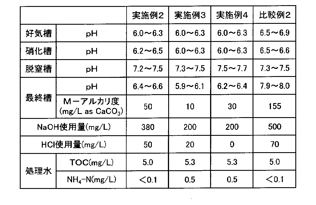
- Table 2 shows the pH and M-alkalinity of each reaction tank in Examples 2 to 4 and Comparative Example 2, the amounts of HCl and NaOH used for the treatment of 1 L of raw water, and the quality of the biological treated water obtained. .
- Example 2 In the treatment method (2), in Example 2, compared to Comparative Example 2, the amount of NaOH and HCl used for neutralization was reduced while maintaining the M-alkalinity of the final tank low.
- Example 3 compared to Example 2, the amount of NaOH used for neutralization was reduced by nearly 50%, and the amount of HCl used was also reduced by about 60%.
- the treated water NH 4 —N of Example 3 was 0.5 mg / L, which was slightly inferior to that of Example 2, but was sufficiently reduced.
- Example 4 the M-alkalinity of the final tank was slightly higher than in Example 3, but the amount of NaOH used for neutralization was the same as in Example 3. The amount of HCl used in Example 4 is zero. The treated water NH 4 —N of Example 4 was equivalent to that of Example 3 and was sufficiently reduced.
- Example 4 If the pH can be adjusted in a range where the M-alkalinity falls within the predetermined range, the method of Example 4 may be used. However, if the M-alkalinity exceeds the predetermined range, an embodiment in which one tank for pH adjustment is added. It is preferable to adopt the method of No. 3.
- treatment method (2) polysulfate was added to biologically treated water (separated water in the sedimentation tank) to perform flocculation treatment, and ion exchange treatment of the flocculated water was performed.
- the aggregation treatment could be carried out at 1/4 of the amount of polysulfate used in Comparative Example 2.
- the regeneration frequency of the ion exchange resin in the subsequent ion exchange treatment could be reduced to 1 ⁇ 4. It was confirmed that a reduction in the amount of neutralizing agent used in biological treatment can reduce the amount of inorganic flocculant used in the subsequent agglomeration treatment and a reduction in the frequency of regeneration of the ion exchange resin in the ion exchange treatment.
Landscapes
- Life Sciences & Earth Sciences (AREA)
- Engineering & Computer Science (AREA)
- Water Supply & Treatment (AREA)
- Chemical & Material Sciences (AREA)
- Hydrology & Water Resources (AREA)
- Environmental & Geological Engineering (AREA)
- Organic Chemistry (AREA)
- Microbiology (AREA)
- Biodiversity & Conservation Biology (AREA)
- Molecular Biology (AREA)
- Health & Medical Sciences (AREA)
- Chemical Kinetics & Catalysis (AREA)
- Nanotechnology (AREA)
- Separation Of Suspended Particles By Flocculating Agents (AREA)
- Purification Treatments By Anaerobic Or Anaerobic And Aerobic Bacteria Or Animals (AREA)
- Activated Sludge Processes (AREA)
- Separation Using Semi-Permeable Membranes (AREA)
- Treatment Of Water By Ion Exchange (AREA)
Abstract
Description
C6H12O6 + 6O2→ 6H2O + 6CO2
6CO2 + 6NaOH → 6NaHCO3
最終段の好気性生物処理槽を含めて少なくとも2槽の好気性生物処理槽を含む2以上の生物処理槽に、電子デバイス製造工程から排出される有機性排水を順次通水して生物処理する際に、最終段の生物処理槽内液のM-アルカリ度が所定値以下となるように、他の生物処理槽において中和剤の添加を行うことにより、中和剤使用量を低減することができる。
本発明は、以下を要旨とする。
本発明で処理対象とする原水は、電子デバイス製造工程から排出される有機性排水である。原水の組成や性状には特に制限はないが、一般的には以下のような性状である。
導電率:100mS/m以下
塩濃度:0.1重量%以下
pH:8~12
TOC:30~2000mg/L
T-N:10~1000mg/L
本発明における生物処理は、直列多段に設けられた2以上の生物処理槽に上記の原水を順次通水するものである。本発明において、この2以上の生物処理のうち少なくとも2槽は好気性生物処理槽(以下「好気槽」と称す場合がある。)であり、そのうちの1槽は最終段の生物処理槽(以下「最終槽」と称す場合がある。)である。
(2) 好気槽→硝化槽→脱窒槽→再曝気槽(→沈殿槽)
(3) 好気槽→硝化槽→再曝気槽(→沈殿槽)
本発明においては、最終槽の好気槽の槽内液のM-アルカリ度が50mg/L as CaCO3以下を維持するように、この最終槽以外の生物処理槽で中和剤添加によるpH調整を行う。
本発明において、中和剤、即ち、酸又はアルカリを添加する生物処理槽は、最終槽以外の槽であればよい。中和剤は、1槽のみに添加しても2槽以上の複数の槽において添加してもよい。
M-アルカリ度は、中性塩由来のアルカリ金属イオンを除いたアルカリ金属イオン濃度を、簡易的にpH4.8における酸消費量を測定して求めることができる。本発明において、最終槽内液のM-アルカリ度は、自動測定装置で連続測定することが望ましい。
第1段目の好気槽のpHを5.0~7.0、好ましくは5.5~6.5、換言すれば、生物活性が維持されるようにpH5.0、好ましくは5.5を下回らない程度とする。同時に、最終槽のM-アルカリ度が低く抑えられるようにpH7.0、好ましくはpH6.5を上回らない程度に制御する。このような制御でも、後段の最終槽の好気槽では、pHの大きな低下を抑えて良好な生物処理を行える。
pH:6.0 → M-アルカリ度:21~25
pH:6.5 → M-アルカリ度:46~49
pH:7.0 → M-アルカリ度:66~69
pH:7.5 → M-アルカリ度:148~154
本発明では、生物処理における中和剤の使用量を低減することができるため、生物処理の後段に凝集分離、RO膜分離、イオン交換処理といった高度処理を行う場合に特に有効である。前述の通り、凝集処理における無機凝集剤使用量の低減、RO膜分離及びイオン交換処理における塩類負荷の低減といった効果を得ることができる。
<組成>
モノエタノールアミン :300mg/L
ジエチレングリコールモノブチルエーテル :250mg/L
テトラメチルアンモニウムヒドロキシド(TMAH):50mg/L
pH:10.5
TOC:292mg/L
T-N:77mg/L
図1に示す、窒素除去を行わない処理方式(1)で原水の生物処理を行った。原水を好気槽1A、好気槽1Bに順次通水して生物処理した後、沈殿槽2で固液分離を行った。槽1A,1Bの合計の水滞留時間(HRT)は、24hrとした。
最終槽である好気槽1Bにおいて、M-アルカリ度をモニタリングしながら、好気槽1Bの槽内液のM-アルカリ度が30mg/L as CaCO3以下となるように、前段の好気槽1AにNaOHを添加して処理を行った。その結果、好気槽1AのpHは6.8~7.0の範囲で変動した。
好気槽1A、1Bの各々において、pHが7.0以上となるように、好気槽1A及び1BにNaOHを添加して処理を行った。その結果、好気槽1AのpHは7.0~7.2の範囲で変動した。

図2に示す窒素除去を行う処理方式(2)で原水の生物処理を行った。原水を好気槽1、硝化槽(好気槽)3、脱窒槽(嫌気槽)4、再曝気槽(好気槽)5に順次通水した後、沈殿槽2で固液分離を行った。通水条件は槽1,3,4,5の合計のHRTを24hrとした。
最終槽である再曝気槽5において、M-アルカリ度をモニタリングしながら再曝気槽5の槽内液のM-アルカリ度が50mg/L as CaCO3以下となるように、かつ好気槽1のpHが6.0を下回らないように、好気槽1にNaOHを添加した。硝化槽3のpHが6.0を下回らないように硝化槽3にNaOHを添加した。脱窒槽4のpHが7.5を超えないように脱窒槽4にHClを添加した。
最終槽である再曝気槽5において、M-アルカリ度をモニタリングしながら、再曝気槽5の槽内液のM-アルカリ度が10mg/L as CaCO3以下となるように、かつ、好気槽1のpHが6.0を下回らないように好気槽1にNaOHを添加した。脱窒槽4のpHが7.5を超えないように脱窒槽4にHClを添加した。
最終槽である再曝気槽5において、M-アルカリ度をモニタリングしながら再曝気槽5の槽内液のM-アルカリ度が30mg/L as CaCO3以下となるように、かつ、好気槽1のpHが6.0を下回らないように、好気槽1にNaOHを添加した。
最終槽である再曝気槽5において、M-アルカリ度はモニタリングは行わず、好気槽1及び硝化槽3のpHがいずれも6.5を下回らないように、好気槽1及び硝化槽3にNaOHを添加した。脱窒槽4のpHが7.5を超えないように脱窒槽4にHClを添加した。再曝気槽のpHが8.0を超えないように再曝気槽にHClを添加した。
本出願は、2014年9月16日付で出願された日本特許出願2014-187799に基づいており、その全体が引用により援用される。
2 沈殿槽
3 硝化槽
4 脱窒槽
5 再曝気槽
Claims (12)
- 電子デバイス製造工程から排出される有機性排水を、直列多段に設けられた2以上の生物処理槽に順次通水する生物処理方法において、
該2以上の生物処理槽のうち少なくとも2槽が好気性生物処理槽であり、
該好気性生物処理槽のうちの1槽は最終段の生物処理槽であり、
該最終段の生物処理槽以外の生物処理槽の少なくとも1槽に酸又はアルカリを添加することによりpH調整する生物処理方法であって、
該最終段の生物処理槽内液のM-アルカリ度が50mg/L as CaCO3以下に維持されるように、前記酸又はアルカリの添加量を制御することを特徴とする生物処理方法。 - 請求項1において、前記最終段の生物処理槽内液のM-アルカリ度又は該M-アルカリ度に相関する指標に基づいて前記酸又はアルカリの添加量を制御することを特徴とする生物処理方法。
- 請求項2において、前記M-アルカリ度に相関する指標は、該酸又はアルカリが添加される生物処理槽内液のpHであり、予め求められた前記M-アルカリ度と該pHとの相関関係に基づいて、前記酸又はアルカリの添加量を制御することを特徴とする生物処理方法。
- 請求項1ないし3のいずれか1項において、前記最終段の生物処理槽以外の好気性生物処理槽として硝化槽を有し、該硝化槽のpHが所定値以上となるように制御することを特徴とする生物処理方法。
- 請求項1ないし4のいずれか1項において、前記最終段の生物処理槽からの処理水に対して、更に凝集分離、逆浸透膜分離、及びイオン交換処理のいずれか1つ以上の高度処理を行うことを特徴とする生物処理方法。
- 請求項5において、前記高度処理水を回収して再利用することを特徴とする生物処理方法。
- 電子デバイス製造工程から排出される有機性排水が、直列多段に設けられた2以上の生物処理槽に順次通水される生物処理装置において、
該2以上の生物処理槽のうち少なくとも2槽が好気性生物処理槽であり、
該好気性生物処理槽のうちの1槽は最終段の生物処理槽であり、
該最終段の生物処理槽以外の生物処理槽の少なくとも1槽に、酸又はアルカリを添加することによりpH調整するpH調整手段を有し、
該最終段の生物処理槽内液のM-アルカリ度が50mg/L as CaCO3以下に維持されるように、該pH調整手段における酸又はアルカリの添加量を制御する制御手段が設けられていることを特徴とする生物処理装置。 - 請求項7において、前記制御手段は、前記最終段の生物処理槽内液のM-アルカリ度又は該M-アルカリ度に相関する指標に基づいて前記pH調整手段の酸又はアルカリの添加量を制御することを特徴とする生物処理装置。
- 請求項8において、前記M-アルカリ度に相関する指標は、該酸又はアルカリが添加される生物処理槽内液のpHであり、前記制御手段は、予め求められた前記M-アルカリ度と該pHとの相関関係に基づいて、前記pH調整手段の酸又はアルカリの添加量を制御することを特徴とする生物処理装置。
- 請求項7ないし9のいずれか1項において、前記最終段の生物処理槽以外の好気性生物処理槽として硝化槽を有し、該硝化槽のpHが所定値以上となるように制御する制御手段を有することを特徴とする生物処理装置。
- 請求項7ないし10のいずれか1項において、前記最終段の生物処理槽からの処理水が導入される、凝集分離手段、逆浸透膜分離手段、及びイオン交換処理手段のいずれか1つ以上の高度処理手段を有することを特徴とする生物処理装置。
- 請求項11において、前記高度処理手段の処理水を回収する回収手段を有し、該回収水が再利用されることを特徴とする生物処理装置。
Priority Applications (5)
| Application Number | Priority Date | Filing Date | Title |
|---|---|---|---|
| CN201580033454.1A CN106470950B (zh) | 2014-09-16 | 2015-07-14 | 生物处理方法及生物处理装置 |
| US15/500,804 US20170217808A1 (en) | 2014-09-16 | 2015-07-14 | Biological treatment method and biological treatment apparatus |
| KR1020167030441A KR20160133003A (ko) | 2014-09-16 | 2015-07-14 | 생물 처리 방법 및 생물 처리 장치 |
| SG11201700623YA SG11201700623YA (en) | 2014-09-16 | 2015-07-14 | Biological treatment method and biological treatment device |
| KR1020187009044A KR20180037306A (ko) | 2014-09-16 | 2015-07-14 | 생물 처리 방법 및 생물 처리 장치 |
Applications Claiming Priority (2)
| Application Number | Priority Date | Filing Date | Title |
|---|---|---|---|
| JP2014187799A JP5929987B2 (ja) | 2014-09-16 | 2014-09-16 | 生物処理方法及び生物処理装置 |
| JP2014-187799 | 2014-09-16 |
Publications (1)
| Publication Number | Publication Date |
|---|---|
| WO2016042901A1 true WO2016042901A1 (ja) | 2016-03-24 |
Family
ID=55532946
Family Applications (1)
| Application Number | Title | Priority Date | Filing Date |
|---|---|---|---|
| PCT/JP2015/070093 Ceased WO2016042901A1 (ja) | 2014-09-16 | 2015-07-14 | 生物処理方法及び生物処理装置 |
Country Status (6)
| Country | Link |
|---|---|
| US (1) | US20170217808A1 (ja) |
| JP (1) | JP5929987B2 (ja) |
| KR (2) | KR20160133003A (ja) |
| CN (1) | CN106470950B (ja) |
| SG (1) | SG11201700623YA (ja) |
| WO (1) | WO2016042901A1 (ja) |
Cited By (3)
| Publication number | Priority date | Publication date | Assignee | Title |
|---|---|---|---|---|
| CN108698866A (zh) * | 2016-03-29 | 2018-10-23 | 栗田工业株式会社 | 生物处理方法及生物处理装置 |
| CN109384345A (zh) * | 2017-08-02 | 2019-02-26 | 中国石油化工股份有限公司 | 一种高盐高钙污水低结垢处理装置及处理工艺 |
| CN109384306A (zh) * | 2017-08-02 | 2019-02-26 | 中国石油化工股份有限公司 | 一种高钙高盐污水脱氮脱cod的处理工艺 |
Families Citing this family (1)
| Publication number | Priority date | Publication date | Assignee | Title |
|---|---|---|---|---|
| JP2020127383A (ja) * | 2019-02-08 | 2020-08-27 | 学校法人 東洋大学 | 培養方法、培養装置、廃水処理方法及び廃水処理装置 |
Citations (5)
| Publication number | Priority date | Publication date | Assignee | Title |
|---|---|---|---|---|
| JPS58174294A (ja) * | 1982-04-02 | 1983-10-13 | Kyowa Kako Kk | 無薬注高度脱窒素・脱燐方法 |
| JPH06206093A (ja) * | 1993-01-13 | 1994-07-26 | Meidensha Corp | 嫌気−好気活性汚泥処理の硝化促進方法及び装置 |
| JPH07313994A (ja) * | 1994-05-23 | 1995-12-05 | Kurita Water Ind Ltd | 超純水の製造方法 |
| JP2011212670A (ja) * | 2010-03-19 | 2011-10-27 | Swing Corp | 排水処理装置及び排水処理方法 |
| JP2013022536A (ja) * | 2011-07-22 | 2013-02-04 | Kurita Water Ind Ltd | アミン含有排水の生物処理法及び処理装置 |
Family Cites Families (4)
| Publication number | Priority date | Publication date | Assignee | Title |
|---|---|---|---|---|
| WO2005030654A1 (ja) * | 2003-09-25 | 2005-04-07 | Ebara Corporation | 硝化処理方法及び装置 |
| US8894857B2 (en) * | 2008-03-28 | 2014-11-25 | Evoqua Water Technologies Llc | Methods and systems for treating wastewater |
| CN101607777B (zh) * | 2009-07-30 | 2011-06-08 | 达斯玛环境科技(北京)有限公司 | 一种鲁奇炉煤气化污水处理与回用方法 |
| US9315396B2 (en) * | 2011-04-06 | 2016-04-19 | Water Conservation Technology International, Inc. | Water conservation methods combining osmotic membrane processed water for subsequent efficient use in cooling tower applications |
-
2014
- 2014-09-16 JP JP2014187799A patent/JP5929987B2/ja active Active
-
2015
- 2015-07-14 KR KR1020167030441A patent/KR20160133003A/ko not_active Ceased
- 2015-07-14 CN CN201580033454.1A patent/CN106470950B/zh active Active
- 2015-07-14 KR KR1020187009044A patent/KR20180037306A/ko not_active Ceased
- 2015-07-14 SG SG11201700623YA patent/SG11201700623YA/en unknown
- 2015-07-14 WO PCT/JP2015/070093 patent/WO2016042901A1/ja not_active Ceased
- 2015-07-14 US US15/500,804 patent/US20170217808A1/en not_active Abandoned
Patent Citations (5)
| Publication number | Priority date | Publication date | Assignee | Title |
|---|---|---|---|---|
| JPS58174294A (ja) * | 1982-04-02 | 1983-10-13 | Kyowa Kako Kk | 無薬注高度脱窒素・脱燐方法 |
| JPH06206093A (ja) * | 1993-01-13 | 1994-07-26 | Meidensha Corp | 嫌気−好気活性汚泥処理の硝化促進方法及び装置 |
| JPH07313994A (ja) * | 1994-05-23 | 1995-12-05 | Kurita Water Ind Ltd | 超純水の製造方法 |
| JP2011212670A (ja) * | 2010-03-19 | 2011-10-27 | Swing Corp | 排水処理装置及び排水処理方法 |
| JP2013022536A (ja) * | 2011-07-22 | 2013-02-04 | Kurita Water Ind Ltd | アミン含有排水の生物処理法及び処理装置 |
Cited By (3)
| Publication number | Priority date | Publication date | Assignee | Title |
|---|---|---|---|---|
| CN108698866A (zh) * | 2016-03-29 | 2018-10-23 | 栗田工业株式会社 | 生物处理方法及生物处理装置 |
| CN109384345A (zh) * | 2017-08-02 | 2019-02-26 | 中国石油化工股份有限公司 | 一种高盐高钙污水低结垢处理装置及处理工艺 |
| CN109384306A (zh) * | 2017-08-02 | 2019-02-26 | 中国石油化工股份有限公司 | 一种高钙高盐污水脱氮脱cod的处理工艺 |
Also Published As
| Publication number | Publication date |
|---|---|
| KR20180037306A (ko) | 2018-04-11 |
| US20170217808A1 (en) | 2017-08-03 |
| JP5929987B2 (ja) | 2016-06-08 |
| SG11201700623YA (en) | 2017-03-30 |
| CN106470950B (zh) | 2018-06-01 |
| CN106470950A (zh) | 2017-03-01 |
| KR20160133003A (ko) | 2016-11-21 |
| JP2016059843A (ja) | 2016-04-25 |
Similar Documents
| Publication | Publication Date | Title |
|---|---|---|
| CN102781849B (zh) | 水处理方法和超纯水制造方法 | |
| CN104058548B (zh) | 一种不锈钢冷轧酸性废水脱氮除盐回用工艺 | |
| CN108249706B (zh) | 一种硅行业废水脱氮除氟及回用的处理方法 | |
| CN103168006B (zh) | 超纯水制造方法 | |
| CN104163516B (zh) | 一种不锈钢冷轧废水的回用方法 | |
| TWI613153B (zh) | 含氨廢水的處理裝置及含氨廢水的處理方法 | |
| CN105152489A (zh) | 一种含氟离子和硝酸根离子的废水的处理方法 | |
| CN104529085A (zh) | 一种油脂水解废水的处理方法 | |
| JP5929987B2 (ja) | 生物処理方法及び生物処理装置 | |
| JP2012005941A (ja) | リン含有廃水の処理装置及び処理方法 | |
| JP2010017615A (ja) | Dmso含有排水の処理方法及び装置 | |
| JP5702221B2 (ja) | エタノールアミンおよびヒドラジン含有排水の処理方法ならびに処理装置 | |
| JP5118376B2 (ja) | 水処理方法及び水処理装置 | |
| TW201802041A (zh) | 生物處理方法及生物處理裝置 | |
| JP2012011376A (ja) | 汚水処理方法および装置 | |
| JP4703370B2 (ja) | 窒素含有排水の処理方法 | |
| JP5217883B2 (ja) | リン酸、硝酸および有機酸含有水の処理方法および処理装置 | |
| US20190077687A1 (en) | Modular method and wastewater treatment arrangement for efficient cleaning of wastewater | |
| JP6649091B2 (ja) | リンの回収方法およびリン回収設備 | |
| JPH1066997A (ja) | 高濃度塩類含有廃水の処理装置 | |
| WO2020080244A1 (ja) | 被処理物の処理方法 | |
| KR101420656B1 (ko) | 시안 함유 폐수 처리 방법 | |
| JPH0561992B2 (ja) | ||
| JP5799633B2 (ja) | アミン含有排水の生物処理法及び処理装置 | |
| CN106103354A (zh) | 含铜废水的处理方法以及处理装置 |
Legal Events
| Date | Code | Title | Description |
|---|---|---|---|
| 121 | Ep: the epo has been informed by wipo that ep was designated in this application |
Ref document number: 15842366 Country of ref document: EP Kind code of ref document: A1 |
|
| ENP | Entry into the national phase |
Ref document number: 20167030441 Country of ref document: KR Kind code of ref document: A |
|
| WWE | Wipo information: entry into national phase |
Ref document number: 15500804 Country of ref document: US |
|
| NENP | Non-entry into the national phase |
Ref country code: DE |
|
| 122 | Ep: pct application non-entry in european phase |
Ref document number: 15842366 Country of ref document: EP Kind code of ref document: A1 |