WO2016042895A1 - 高圧燃料供給ポンプ - Google Patents
高圧燃料供給ポンプ Download PDFInfo
- Publication number
- WO2016042895A1 WO2016042895A1 PCT/JP2015/069815 JP2015069815W WO2016042895A1 WO 2016042895 A1 WO2016042895 A1 WO 2016042895A1 JP 2015069815 W JP2015069815 W JP 2015069815W WO 2016042895 A1 WO2016042895 A1 WO 2016042895A1
- Authority
- WO
- WIPO (PCT)
- Prior art keywords
- valve
- fuel supply
- supply pump
- pressure fuel
- valve body
- Prior art date
- Legal status (The legal status is an assumption and is not a legal conclusion. Google has not performed a legal analysis and makes no representation as to the accuracy of the status listed.)
- Ceased
Links
Images



Classifications
-
- F—MECHANICAL ENGINEERING; LIGHTING; HEATING; WEAPONS; BLASTING
- F02—COMBUSTION ENGINES; HOT-GAS OR COMBUSTION-PRODUCT ENGINE PLANTS
- F02M—SUPPLYING COMBUSTION ENGINES IN GENERAL WITH COMBUSTIBLE MIXTURES OR CONSTITUENTS THEREOF
- F02M51/00—Fuel-injection apparatus characterised by being operated electrically
- F02M51/04—Pumps peculiar thereto
-
- F—MECHANICAL ENGINEERING; LIGHTING; HEATING; WEAPONS; BLASTING
- F02—COMBUSTION ENGINES; HOT-GAS OR COMBUSTION-PRODUCT ENGINE PLANTS
- F02M—SUPPLYING COMBUSTION ENGINES IN GENERAL WITH COMBUSTIBLE MIXTURES OR CONSTITUENTS THEREOF
- F02M59/00—Pumps specially adapted for fuel-injection and not provided for in groups F02M39/00 -F02M57/00, e.g. rotary cylinder-block type of pumps
- F02M59/44—Details, components parts, or accessories not provided for in, or of interest apart from, the apparatus of groups F02M59/02 - F02M59/42; Pumps having transducers, e.g. to measure displacement of pump rack or piston
- F02M59/46—Valves
Definitions
- the present invention relates to a high-pressure fuel supply pump that supplies fuel to an internal combustion engine at a high pressure, and particularly relates to a high-pressure fuel supply pump having a relief valve structure that exhibits stable and high fuel release characteristics.
- Patent Document 1 discloses a structure in which a fluid throttle is provided on a side surface of a relief valve to form an intermediate chamber, and a valve body lift is increased by pressure stored therein.
- Patent Document 2 discloses a structure that stabilizes the behavior of a relief valve of a hydraulic continuously variable transmission by guiding a valve body.
- the pressure loss generated in the fluid throttle provided on the side surface of the relief valve causes pressure accumulation in an intermediate chamber formed between the seat portion and the fluid throttle, This is configured to act on the bottom surface of the valve body. Thereby, the fluid force in the valve opening direction acts on the valve body, the lift is increased, and high opening performance can be obtained.
- the valve body may be eccentric in the radial direction.
- the shape of the annular gap provided on the side surface changes.
- the differential pressure generated between the front and the rear theoretically decreases to 1 / 2.5 times that when there is no eccentricity.
- the pressure in the intermediate chamber is greatly affected by the eccentricity of the valve body, and the lift and release characteristics vary.
- Patent Document 2 discloses a structure that guides a valve body and stabilizes its behavior.
- a fluid throttle is not formed on the side surface of the valve body, and high opening characteristics cannot be expected.
- the relief valve is built in the discharge valve, and the guide portion is not fixed to the pump body. For this reason, there is a possibility that the valve body behavior cannot be sufficiently stabilized due to the movement of the guide portion itself.
- an object of the present invention is to provide a relief valve structure that stably exhibits high fuel release characteristics and a high-pressure fuel supply pump equipped with the relief valve structure with a small and inexpensive structure.
- the suction passage, the pressurizing chamber, and the discharge passage are sequentially formed in the body from the upstream side, and a discharge valve that restricts the flow direction of fuel is disposed in the discharge passage.
- a high pressure fuel supply pump in which a relief valve is arranged in a relief passage formed between an upstream side and a downstream side, wherein the relief valve is a seat portion that seals fuel by contacting a valve body with a valve seat portion.
- a fluid passage that includes a part of the valve body to form a fluid throttle, a guide part that is formed integrally with the valve body, a slidably holding the guide part, and a radial direction of the valve body And a cylindrical wall portion that suppresses eccentricity to the surface.
- the embodiment of the present invention is preferably configured as follows.
- the guide portion is disposed inside a return spring that urges the valve body to the valve seat portion, and a fluid throttle is formed by a gap formed between the housing housing the relief valve component and the valve body, The sheet part and the guide part are integrally formed.
- a stopper is provided so as to restrict the movement of the valve body before the return springs are in close contact with each other.
- the stopper may be formed of a member that receives the urging force of the return spring, may be formed directly on the pump body, or may be formed of another member that has been subjected to heat treatment or surface treatment.
- the fluid throttle may be formed by an annular gap formed on the side surface of the valve body or a through-hole penetrating the valve body. Furthermore, when assembling, after inserting a valve body in a housing, a return spring may be fitted, it may unitize by fixing with a stator, and the method fixed to a pump body after that may be taken.
- a relief valve structure that stably exhibits high fuel release characteristics and a high-pressure fuel supply pump equipped with the relief valve structure can be realized with a small and inexpensive structure.
- the figure which shows the cross section of the relief valve 30 which concerns on Example 1 of this invention The figure which shows the whole high-pressure fuel supply pump system structure with which the Example of this invention is applied.
- FIG. The figure which shows the cross section of the relief valve 30 which concerns on Example 2 of this invention.
- FIG. 2 shows the overall configuration of a high-pressure fuel supply pump system to which the embodiments of the present invention (Embodiments 1 to 4) are applied. For this reason, the overall configuration will be described first with reference to FIG. 2, and then each embodiment of the relief valve structure will be described.
- the high-pressure fuel supply pump system shown in FIG. 2 is roughly divided into a fuel tank fuel tank 101 on the left side in the figure, a high-pressure fuel supply pump 300 in the center in the figure, a fuel injection system 200 on the right side in the figure (common rail 53, injector 54, etc.), engine A control unit (ECU) 40 and an internal combustion engine 400 in the lower center of the figure (lower side of the high-pressure fuel supply pump 1) are configured.
- ECU engine A control unit
- the high-pressure fuel supply pump 300 has a plurality of components and mechanisms integrally incorporated in the body 1 and is attached to the cylinder head 20 of the internal combustion engine 400.
- a suction passage 9, a pressurizing chamber 11, a discharge passage 12, and a relief passage 15 are formed in the body 1.
- the suction passage 9 is provided with an electromagnetic valve 5
- the discharge passage 12 is provided with a discharge valve 8
- the relief passage 15 is provided with a relief valve 30.
- the pressurizing chamber 11 in the body 1 is changed in volume by the plunger 2 that moves up and down by the rotation of the cam 7 of the internal combustion engine, so that the pump operation is possible.
- the functions of the respective valves formed in the high-pressure fuel supply pump 300 will be briefly described.
- the electromagnetic valve 5 is an adjustment valve that determines the amount of fuel to be pressurized, and the discharge valve 8 changes the fuel flow direction.
- the relief valve 30 serves as a safety valve that opens the common rail 53 when the pressure in the common rail 53 exceeds a predetermined pressure.
- the high-pressure fuel supply pump system configured as described above, fuel from the fuel tank 101 is guided into the high-pressure fuel supply pump 300, and the solenoid valve 5 in the suction passage 9, the pressurizing chamber 11, and the discharge valve 8 in the discharge passage 12.
- the pressure is increased by passing through and is supplied to the fuel injection system 200.
- the high-pressure fuel supply pump is connected to the common rail 53 of the fuel injection system 200, the pressurized fuel is pumped, and the high-pressure fuel is injected from the injector 54 into the combustion chamber of the internal combustion engine.
- the pressure in the common rail 53 is measured by the pressure sensor 56, and the signal is sent to the engine control unit (ECU) 40.
- the injectors 54 are mounted in accordance with the number of cylinders of the engine, and inject fuel with a signal from an engine control unit (ECU) 40.
- the engine control unit (ECU) 40 controls the electromagnetic valve 5 in the high pressure fuel supply pump.
- the high-pressure fuel supply pump system in FIG. 2 is configured as described above.
- the present invention relates to the improvement of the relief valve 30, but before that, each function of the high-pressure fuel supply pump will be described in more detail.
- the plunger 2 below the pressurizing chamber 11 is slidably inserted into the cylinder 120, and the retainer 3 is attached to the lower end.
- the urging force of the plunger return spring 4 acts on the retainer 3 in the downward direction in FIG.
- the tappet 6 reciprocates in the vertical direction in FIG. 2 by the rotation of the cam 7 of the internal combustion engine. Since the plunger 2 is displaced following the tappet 6, this changes the volume of the pressurizing chamber 11 and enables the pump operation.
- the electromagnetic valve 5 is held by the body 1, and an electromagnetic coil 500, a mover 503, an anchor spring 502, and a valve body spring 504 are arranged.
- an electromagnetic coil 500, a mover 503, an anchor spring 502, and a valve body spring 504 are arranged.
- the description will be made on the assumption that the movable portion 503 is formed of one member.
- the movable portion 503 may be formed of two members including an anchor that forms a magnetic attraction surface and a rod that forms a sliding portion. Good.
- An electromagnetic valve system in which the electromagnetic coil 500 is opened when the electromagnetic coil 500 is OFF and closed when the electromagnetic coil 500 is ON is referred to as a normal open system.
- the urging force of the anchor spring 502 acts on the valve body 501 in the valve opening direction via the movable portion 503, and similarly, the urging force of the valve body spring 504 acts on the valve body 501 in the valve closing direction.
- the valve body 501 is in the valve open state when the electromagnetic coil 500 is OFF (non-energized).
- the operation is reversed, that is, even if a system using an electromagnetic valve system called a normally closed system in which the valve body 501 is closed when the electromagnetic coil 500 is OFF (no power supply) is the same. It is possible to implement Example 1 to Example 4.
- the relief valve 30 is formed by a valve body 151 and a valve seat 157.
- a method of opening the abnormal high pressure generated on the common rail 53 side to the pressurizing chamber 11 is referred to as a pressurizing chamber returning method.
- the relief valve 30 in FIG. 2 is formed in the relief passage 15, and the relief passage 15 is connected to the downstream side (fuel injection system 200 side) of the discharge valve 8 and the pressurizing chamber 11.
- a valve body 151 is arranged in a direction to open from the downstream side to the pressurizing chamber 11 side.
- the valve body 151 is biased to the valve seat portion 157 by a return spring 154, and a seat portion 150 that seals fuel is formed at a contact portion between the two.
- the behavior of the valve body 151 is governed by the differential pressure generated before and after the seat portion 150. When the differential pressure generated thereby overcomes the urging force of the return spring 154, the valve opening operation is started.
- the first to fourth embodiments can be similarly implemented on the premise of a system using a low pressure return system in which the relief passage 15 is connected to the downstream side of the discharge valve 8 and the damper chamber 51. .
- the suction process the state in which the plunger 2 is displaced downward in FIG. 2 due to the rotation of the cam 7 of the internal combustion engine is referred to as a suction process
- the state in which the plunger 2 is displaced upward is referred to as a compression process.
- the suction process the volume of the pressurizing chamber 11 increases and the fuel pressure therein decreases.
- the valve body 501 of the electromagnetic valve 5 is opened and the fuel is sucked into the pressurizing chamber 11.
- the valve body 501 of the electromagnetic valve 5 still remains even if the plunger 2 shifts from the suction process to the compression process. Keep the valve open. Accordingly, even during the compression process, the pressure in the pressurizing chamber 11 is maintained at a low pressure almost equal to that of the suction passage 9, so that the discharge valve 8 cannot be opened, and the fuel corresponding to the volume reduction in the pressurizing chamber 11 is achieved. Passes through the electromagnetic valve 5 and is returned to the damper chamber 51 side. This process is called a return process.
- the flow rate discharged by the pump can be controlled by adjusting the timing at which the electromagnetic coil 500 is turned on.
- FIG. 1 shows a cross-sectional view of a relief valve 30 according to Embodiment 1 of the present invention.
- 1 is a body of a high-pressure fuel supply pump
- 150 is a seat
- 151a is a ball valve
- 151b is a valve body holder
- 153a is a through hole
- 154 is a return spring
- 155a is a stator
- 156 is a housing
- 157 is
- 158 is a guide portion
- 160 is an intermediate chamber
- 161 is a pressure receiving area.
- the ball valve 151a and the valve body holder 151b together constitute a valve body 151. Both can be formed as one member, but the processing cost can be reduced by using a ball-shaped commercial material for the portion where the sheet portion 150 is formed.
- the ball valve 151a is urged in the direction of the valve seat portion 157 by the return spring 154 via the valve element holder 151b, and a seat portion 150 for sealing fuel is formed at the contact portion between the two.
- the behavior of the valve body 151 is governed by the differential pressure generated before and after the seat portion 150.
- the valve body 151 opens to the left side of the drawing.
- the press-fitting depth of the stator 155a fixed to the housing 156 by press-fitting it is possible to adjust the biasing force of the return spring 154 and change the differential pressure at which the valve opening operation starts. is there.
- the fuel passes through the seat portion 150 and reaches the intermediate chamber 160, and is opened through a through hole 153a provided as a fluid passage in a part of the valve body 151.
- Providing the through hole 153a in a part of the valve body 151 is advantageous from the viewpoint of space saving compared to the case of providing a new fluid passage separately from the valve body 151.
- the through hole 153a forms a fluid throttle that generates a pressure loss with respect to the flow, whereby pressure is stored in the intermediate chamber 160. With such a configuration, the pressure stored in the intermediate chamber 160 acts on the pressure receiving surface 161 formed on the end surface of the valve body holder 151b, and the valve opening lift of the valve body 151 can be increased.
- a high opening characteristic can be obtained with a small and simple relief valve structure. Furthermore, a guide portion 158 that suppresses eccentricity in the radial direction is provided on a side surface of the valve body holder 151b. Thereby, the behavior of the valve body 151 is stabilized, and a more stable opening characteristic can be obtained.
- the valve body 151 stops at a position determined by the gap between the spring lines of the compressed return spring 154.
- each part is assembled to the housing 156 and fixed by the stator 155a, and once unitized, the housing 156 is press-fitted into the pump body 1, thereby improving the assembly performance and reducing the assembly cost. Can be reduced.
- attachment procedure of each component is demonstrated. First, the ball valve 151 a and the valve body holder 151 b are inserted into the housing 156. Thereafter, the return spring 154 is inserted, and the stator 155a is press-fitted and fixed to form a unit.
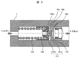
- FIG. 3 shows a modification of the first embodiment.
- the housing 156 is not used, and the components are directly assembled to the pump body 1. By doing so, it is possible to make the structure cheaper.
- the return spring 154 is inserted into the pump body 1, and then the valve body holder 151b and the ball valve 151a are inserted. Finally, the valve seat 157 is fixed by press fitting. Further, it is possible to adjust the biasing force of the return spring 154 by adjusting the press-fitting depth.
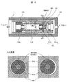
- FIG. 4 is a view showing the relief valve structure described in Patent Document 1 described above. Due to the pressure loss generated by the fluid throttle provided on the side surface of the relief valve, pressure is accumulated in the intermediate chamber formed between the seat portion and the fluid throttle, and this is applied to the bottom surface of the valve body. As apparent from the comparison with FIG. 1, the difference is that a guide portion 158 that suppresses radial eccentricity is provided on the side surface of the valve element holder 151b. According to the configuration of FIG. 4 that does not include the guide portion 158, the valve body 151 is eccentric in the radial direction as shown in the lower part of FIG. 4, and when the valve body 151 is eccentric, the annular gap provided on the side surface As the shape changes, the pressure in the intermediate chamber is greatly influenced by the eccentricity of the valve body, and the lift and release characteristics vary.
- the guide body 158 in the relief passage 15 direction is formed integrally with the valve body 151, and the circumferential cross section of the guide section 158 has the same shape as the cross section of the relief passage 15, thereby decentering the valve body 151. It has been prevented.
- the guide part 158 integrally formed in the relief passage 15 direction of the valve body 151 operates as an eccentricity prevention mechanism.
- the relief passage 15 is a passage formed by the housing 156 in the body 1 in the case of FIG. 1, and is a passage directly formed by the body 1 in the case of FIG.
- the area variation of the fluid throttle can be reduced by the guide portion.
- the guide portion prevents the fluid throttle from tilting.
- the high-pressure fuel supply pump is configured such that the suction passage, the pressurization chamber, and the discharge passage are sequentially formed in the body from the upstream side, and the solenoid valve and the discharge passage determine the fuel amount in the suction passage.
- the relief valve is provided with a valve body and a valve provided in the relief passage.
- a high pressure fuel supply pump in which a seat portion for sealing fuel is formed by contact of a seat portion, and a fluid passage including a part of the valve body and forming a fluid throttle is provided in addition to the seat portion .
- it further includes a cylindrical wall portion formed in the relief passage, and a guide portion that slides in the wall portion and is formed integrally with the valve body.
- the guide portion deflects the valve body in the radial direction. The lead is suppressed.
- the cylindrical wall portion formed in the relief passage is the housing 156, and the guide portion that slides in the wall portion and is formed integrally with the valve body is the guide portion 158.
- the cylindrical wall portion formed in the relief passage is the body 1, and the guide portion that slides in the wall portion and is formed integrally with the valve body is the guide portion 158.
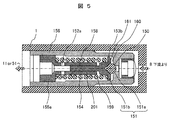
- FIG. 5 shows a sectional view of the relief valve according to the second embodiment of the present invention.
- 1 is a pump body
- 150 is a seat portion
- 151a is a ball valve
- 151b is a valve body holder
- 152a is a vertical hole passage
- 153b is an annular gap
- 154 is a return spring
- 155a is a stator
- 156 is a housing, 157 ,
- the ball valve 151a and the valve body holder 151b together constitute a valve body 151. Both can be formed as one member, but the processing cost can be reduced by using a ball-shaped commercial material for the portion where the sheet portion 150 is formed.
- the guide portion 158 as an eccentricity prevention mechanism is provided on the inner diameter side of the return spring 154.
- the valve body 151 formed integrally with the guide portion 158 is disposed on the downstream side of the discharge valve of the relief passage 15, and the inner cylinder is formed on the valve body 151 side from the stator 155 a on the upstream side of the discharge valve of the relief passage 15. 201 is fixedly arranged.
- the guide portion 158 is fitted in the inner cylinder 201 and configured to be movable.
- the valve body holder 151b can be downsized, and the annular gap 153b can be formed as a fluid passage on the side surface thereof. Then, by providing the annular gap 153b with the same fluid throttling effect as the through hole 153a described in the first embodiment, it is possible to obtain a high opening characteristic.
- the fluid passage is formed by the annular gap 153b, it is not necessary to perform a highly accurate and expensive fine hole processing. For this reason, it is more advantageous from the viewpoint of cost reduction as compared with the case where the fluid passage is formed by the through hole 153a of FIGS.
- the fuel passes through the annular gap 153b and then passes through the vertical hole passage 152a provided in the stator 155a to be released.
- a stopper 159 is provided at the end of the stator 155a. Even when the lift of the valve body 151 increases, the lift amount is limited to a predetermined value or less by contacting the stopper 159. Thereby, it can prevent that the line
- the stator 155a that receives the biasing force of the return spring 154 and the stopper 159 from the same member, the maximum lift amount of the valve element 151 can be accurately determined with respect to the gap between the lines of the return spring 154. it can.
- each area is set so that the cross-sectional area of the annular gap 153 b is smaller than the opening area of the seat portion 150 in the fully opened state where the valve body 151 contacts the stopper 159.
- the present invention includes a cylindrical wall portion formed in the relief passage, and a guide portion that slides in the wall portion and is formed integrally with the valve body, and is guided in the radial direction of the valve body by the guide portion.
- the cylindrical wall part formed in the relief passage is a hollow inner cylinder 201, and slides in the wall part so as to be integrated with the valve body.
- the formed guide part corresponds to the guide part 158.
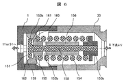
- FIG. 6 shows a sectional view of the relief valve according to the third embodiment of the present invention.
- 1 is a pump body
- 150 is a seat part
- 152b is a vertical hole passage
- 153b is an annular gap
- 154 is a return spring
- 155b is a stator
- 156 is a housing
- 157 is a valve seat part
- 158 is a guide part
- Reference numeral 159 denotes a stopper
- 160 denotes an intermediate chamber
- 161 denotes a pressure receiving surface
- 162 denotes a slit.
- the return spring 154 that is disposed closer to the pressurizing chamber 11 than the seat portion 150 in the first and second embodiments is disposed on the downstream side of the discharge valve 8 that is opposite to the return spring 154.
- the guide portion 158 as an eccentricity prevention mechanism is provided on the inner diameter side of the return spring 154.
- the valve body 151 formed integrally with the guide portion 158 is disposed on the upstream side of the discharge valve of the relief passage 15, and the stator 155b for fixing the return spring 154 is disposed on the downstream side of the discharge valve of the relief passage 15.
- a housing 156 (corresponding to the inner cylinder 201 in FIG.
- a guide portion 158 is fitted in the housing 156 so as to be movable.
- the stator 155b is fixed to the downstream side of the discharge valve of the guide portion 158.
- the return spring 154 is excluded from the pressurizing chamber 11, and a space formed excessively around the return spring 154 can be excluded. This leads to a reduction in the useless volume in the pressurizing chamber 11 which is a main factor of a decrease in volumetric efficiency, and an improvement effect can be expected especially at high pressure where the tendency of volumetric efficiency to decrease is remarkable.
- the valve body 151 when the valve body 151 is opened, the fuel flowing from the downstream side of the discharge valve 8 passes through the vertical hole passage 152b and is guided to the intermediate chamber 160 through the seat portion 150.
- the annular gap 153b serving as a fluid passage is formed by the side surface of the valve body 151 and the inner wall surface of the housing 156, and has a fluid throttle effect.
- the housing 156 is integrally formed with a cylindrical wall portion that receives the seat portion 150 and the guide portion 158.
- a stopper 159 for limiting the lift of the valve body 151 is provided on the pump body 1. By doing so, it is possible to prevent the return springs 154 from coming into close contact with each other with a simpler structure, and to obtain a stable opening characteristic. Further, a slit 161 is provided in a portion where the stopper 159 is formed, and the fuel that has passed through the annular gap 153b is released through the slit 162. The same effect can be obtained even if the slit 162 is provided on the end side of the valve body 151.
- the stopper 159 may be formed of a heat-treated or surface-treated member separately from the pump body 1. By doing so, it is possible to improve the wear resistance and maintain a stable open characteristic for a long period of time.
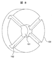
- An example of the stopper 159 in FIG. 7 is preferably configured as shown in FIG. A fuel passage 181 is formed at the center of the circular member, and slits 162 are provided, for example, in four directions from the center.
- the valve body 1 stops at a stopper 159 on the member surface (right side in the figure).
- each part is assembled to the housing 156 and fixed by the stator 155b, and once unitized, the housing 156 is press-fitted into the pump body 1 and assembled, and the discharge joint 30 is attached. Thereby, assemblability improves and assembly cost can be reduced.
- attachment procedure of each component is demonstrated. First, the valve body 151 is inserted into the housing 156. Thereafter, the return spring 154 is inserted, and the stator 155b is press-fitted and fixed to form a unit.
- the cylindrical wall portion formed in the relief passage is the housing 156, and the guide portion that slides in the wall portion and is formed integrally with the valve body corresponds to the guide portion 158. To do.
- FIG. 10 shows a sectional view of the relief valve according to the fourth embodiment of the present invention.
- 1 is a pump body
- 150 is a seat portion
- 152b is a vertical hole passage
- 153a is a through hole
- 154 is a return spring
- 155b is a stator
- 156 is a housing
- 157 is a valve seat portion
- 158a and 158b are guide portions.
- 159 is a stopper
- s60 is an intermediate chamber
- 161 is a pressure receiving surface
- 162 is a slit.
- the guide portion 158 that is one place in the third embodiment is arranged in two places 158a and 158b.
- eccentricity of the valve body in the radial direction can be suppressed with higher accuracy.
- the fuel that has passed through the seat portion 150 passes through a through hole 153a provided as a fluid passage in the valve body 151, and is released.
- the through hole 153a has a fluid throttling effect as in the first embodiment, and pressure is stored in the intermediate chamber 160.
- the urging force of the return spring 154 is received by the stator 155b on the upstream side (the right side in the drawing) of the seat portion 150, so that a sufficient space for providing the through hole 153a is secured.
- the penetration distance is short, an increase in processing cost can be suppressed.
- the cylindrical wall portion formed in the relief passage is the housing 156, and the guide portion that slides in the wall portion and is formed integrally with the valve body corresponds to the guide portion 158. To do.
- a relief valve that exhibits a more stable and high opening characteristic while maintaining volumetric efficiency even at high pressure as in the case of the third embodiment is realized by a small and inexpensive structure. It is possible.
- the fluid throttle is realized by making the cross-sectional area of the fluid passage smaller than the opening area of the seat portion when the valve body is fully open.
- valve body By guiding the valve body, it is possible to minimize the change in the cross-sectional area of the fluid throttle including a part of the valve body. Thereby, it is possible to prevent the differential pressure generated before and after the fluid throttling from changing, and to stabilize the differential pressure. And valve body behavior and an opening characteristic can be stabilized.
- the space can be used effectively, and downsizing can be realized.
- tolerance management such as a gap width becomes easier than in the case of separate formation. Thereby, the change in the cross-sectional area of the fluid throttle can be reduced at low cost, and the opening characteristics can be stabilized.
- the stopper for restricting the movement of the valve body can prevent the flow from being closed between the lines of the return spring even when the valve body lift increases, and a stable opening characteristic can be obtained. .
- the stopper By forming the stopper separately from the pump body with a heat treatment material or the like, the wear resistance can be improved, and a stable opening characteristic can be obtained even during long-term operation.
- the fluid throttle can be formed with an annular gap or a through hole, and the type can be flexibly selected according to the location. Thereby, useless space can be utilized and size reduction can be realized. Furthermore, it is good also as a structure once assembled as a unit outside a pump body at the time of an assembly. By doing so, the assemblability can be improved and the mass production cost can be reduced.
- the present invention is not limited to high-pressure fuel supply pumps for internal combustion engines, and can be widely used for various high-pressure pumps.
Landscapes
- Engineering & Computer Science (AREA)
- Chemical & Material Sciences (AREA)
- Combustion & Propulsion (AREA)
- Mechanical Engineering (AREA)
- General Engineering & Computer Science (AREA)
- Fuel-Injection Apparatus (AREA)
Abstract
本発明の目的は、安定して高い燃料開放特性を発揮するリリーフ弁構造と、それを搭載した高圧燃料供給ポンプを、小型かつ安価な構造により提供することである。本発明の高圧燃料供給ポンプは、ボディ内に上流側から吸入通路、加圧室、吐出通路が順次形成され、前記吐出通路には燃料の流通方向を制限する吐出弁が配置され、前記吐出弁の上流と下流との間に形成されたリリーフ通路にリリーフ弁が配置された高圧燃料供給ポンプであって、 前記リリーフ弁は、弁体が弁座部と接触することで燃料をシールするシート部と、前記弁体の一部を含んで流体絞りを形成する流体通路と、前記弁体と一体に形成されたガイド部と、前記ガイド部を摺動可能に保持するとともに前記弁体の径方向への偏芯を抑制する筒状の壁部と、を有することを特徴とする。
Description
本発明は、内燃機関に燃料を高圧で供給する高圧燃料供給ポンプに係り、特に安定して高い燃料開放特性を発揮するリリーフ弁構造を備えた高圧燃料供給ポンプに関する。
昨今、内燃機関の小型・高効率・低排気化が精力的に進められている。これを受け、高圧燃料供給ポンプには、内燃機関への搭載性を向上させるボディの小型化、および高効率
・低排気化に対応する吐出燃料の高圧化や容積効率の向上が強く求められている。
・低排気化に対応する吐出燃料の高圧化や容積効率の向上が強く求められている。
これらの要求である高圧燃料供給ポンプのさらなる高圧化に向けて、最も重要な課題の一つとなっているのが、高圧燃料供給ポンプ内部のリリーフ弁の開発である。リリーフ弁は、燃料供給システム全体の最大許容圧力を決定するため、その燃料開放特性に対する改善要求は厳しいものがある。このため、安定して高い開放性能を発揮するリリーフ弁の開発が求められている。
この点に関し、従来からリリーフ弁の構造に関して各種提案がなされている。その中で、例えば特許文献1には、リリーフ弁の側面に流体絞りを設けて中間室を形成し、そこに蓄えた圧力により弁体リフトを増大させる構造が開示されている。また特許文献2には、油圧式無段変速機のリリーフ弁に関して、弁体をガイドすることで挙動を安定させる構造が開示されている。
リリーフ弁の開放特性を向上させる例として、特許文献1の例では、リリーフ弁側面に設けた流体絞りで発生する圧力損失により、シート部と流体絞りの間に形成された中間室に蓄圧し、これを弁体底面に作用させる構成としている。これにより、弁体に開弁方向の流体力が作用し、リフトが増大して高い開放性能を得ることができる。
しかしながら、この構造では弁体が径方向に偏芯してしまう可能性がある。弁体が偏芯すると、側面に設けられた環状隙間の形状が変化する。その結果、前後に発生する差圧は、理論上、偏芯がない場合の1/2.5倍まで低下する可能性がある。このため、中間室の圧力は弁体の偏芯により大きな影響を受け、リフトおよび開放特性にばらつきが生じる。
以上で述べた偏芯の影響は、弁体側面に流体絞りを設けることでより顕著となった新たな課題である。これを解決するためには、前述した開放特性のばらつきが発生しても許容値内に収まるよう、隙間幅の寸法精度を高めて対応する必要があり、低コスト化の観点から好ましくない。
また特許文献2には、弁体をガイドして挙動を安定させる構造が開示されている。しかしながら、この構造では弁体側面に流体絞りは形成されておらず、高い開放特性は期待できない。また、吐出弁にリリーフ弁を内蔵する構造を前提としており、ガイド部がポンプボディに固定されていない。このため、ガイド部自体が移動してしまうことにより、弁体挙動を十分に安定させられない可能性がある。
以上のことから本発明では、安定して高い燃料開放特性を発揮するリリーフ弁構造と、それを搭載した高圧燃料供給ポンプを、小型かつ安価な構造により提供することを目的とする。
以上のことから本発明においては、ボディ内に上流側から吸入通路、加圧室、吐出通路が順次形成され、前記吐出通路には燃料の流通方向を制限する吐出弁が配置され、前記吐出弁の上流と下流との間に形成されたリリーフ通路にリリーフ弁が配置された高圧燃料供給ポンプであって、前記リリーフ弁は、弁体が弁座部と接触することで燃料をシールするシート部と、前記弁体の一部を含んで流体絞りを形成する流体通路と、前記弁体と一体に形成されたガイド部と、前記ガイド部を摺動可能に保持するとともに前記弁体の径方向への偏芯を抑制する筒状の壁部と、を有することを特徴とする。
なお本発明の実施例ではさらに以下のように構成するのがよい。ガイド部を、弁体を弁座部に付勢する戻しばねの内側に配置し、リリーフ弁部品を収納するハウジングと弁体の間に形成される隙間によって流体絞りを形成して、前記ハウジングにシート部およびガイド部を一体形成する。
さらに、弁体が開弁方向に移動した際、戻しばねの線間が密着する前に、弁体の移動を規制するようストッパを設ける。そして、ストッパを戻しばねの付勢力を受ける部材で形成したり、ポンプボディに直接形成したり、熱処理や表面処理をした別部材で形成してもよい。
なお、流体絞りは弁体の側面に形成される環状隙間や、弁体を貫通する貫通穴で形成してもよい。さらに、組み立てる際、ハウジングに弁体を挿入した後、戻しばねを嵌合し、固定子で固定することでユニット化し、その後ポンプボディに固定する方法を取ってもよい。
本発明の構成によれば、安定して高い燃料開放特性を発揮するリリーフ弁構造と、それを搭載した高圧燃料供給ポンプを、小型かつ安価な構造で実現することができる。
以下、図を参照して、本発明の実施形態について説明する。
実施例1について、図1、図2、図3を用いて説明する。このうち図2は、本発明の実施例(実施例1から実施例4)が適用される高圧燃料供給ポンプシステムの全体構成を示している。このため、最初に図2を用いて全体構成の説明を行い、そのあとでリリーフ弁構造の各実施例について説明することにする。
図2の高圧燃料供給ポンプシステムは、これを大別すると図示左側の燃料タンク燃料タンク101、図示中央の高圧燃料供給ポンプ300、図示右側の燃料噴射系200(コモンレール53、インジェクタ54など)、エンジンコントロールユニット(ECU)40、図示中央下側(高圧燃料供給ポンプ1の下側)の内燃機関400で構成されている。
高圧燃料供給ポンプ300は、ボディ1内に複数の部品や機構を一体に組み込んでおり、内燃機関400のシリンダヘッド20に取り付けられている。ボディ1には、吸入通路9、加圧室11、吐出通路12、リリーフ通路15が形成されている。吸入通路9には電磁弁5、吐出通路12には吐出弁8、リリーフ通路15にはリリーフ弁30が設けられている。またボディ1内の加圧室11は、内燃機関のカム7の回転により上下動するプランジャ2により容積が変化してポンプ動作が可能となる。上記の高圧燃料供給ポンプ300内に形成された各弁の機能は、これを簡便に説明すると、電磁弁5は加圧する燃料量を決定する調整弁であり、吐出弁8は燃料の流通方向を制限する逆止弁であり、リリーフ弁30はコモンレール53内が所定の圧以上となった際に、それを開放する安全弁の機能を果たすものとなっている。
概略上記構成の高圧燃料供給ポンプシステムによれば、燃料タンク101からの燃料は高圧燃料供給ポンプ300内に導かれ、吸入通路9の電磁弁5、加圧室11、吐出通路12の吐出弁8を経由することで高圧化され、燃料噴射系200に与えられる。高圧燃料供給ポンプは、燃料噴射系200のコモンレール53に接続されており、昇圧された燃料が圧送され、高圧の燃料はインジェクタ54から内燃機関の燃焼室へと噴射される。コモンレール53内の圧力は、圧力センサ56により計測され、その信号はエンジンコントロールユニット(ECU)40へ送られる。インジェクタ54は、エンジンの気筒数にあわせて装着されており、エンジンコントロールユニット(ECU)40の信号にて燃料を噴射する。またエンジンコントロールユニット(ECU)40は、高圧燃料供給ポンプ内の電磁弁5を制御している。
図2の高圧燃料供給ポンプシステムは概略以上のように構成されている。本発明はリリーフ弁30の改良に関するものであるが、その前に高圧燃料供給ポンプの各部機能についてそれぞれさらに詳しく説明しておく。
まず、加圧室11によりポンプ動作を行わせしめるための内燃機関との接続関係について説明する。加圧室11下部のプランジャ2は、シリンダ120に摺動可能に挿入されており、下端にはリテーナ3が取り付けられている。リテーナ3にはプランジャ戻しばね4の付勢力が図2の下方向に作用している。タペット6は、内燃機関のカム7の回転により、図2の上下方向に往復する。プランジャ2はタペット6に追従して変位するため、これにより加圧室11の容積が変化してポンプ動作が可能となる。
次にエンジンコントロールユニット(ECU)40の信号にて制御される高圧燃料供給ポンプ内の電磁弁5の構成について説明する。電磁弁5はボディ1に保持されており、電磁コイル500、可動子503、アンカーばね502、弁体ばね504が配されている。以降では、可動部503が1部材で形成される場合を前提に説明を進めるが、可動部503は磁気吸引面を形成するアンカーと、摺動部を形成するロッドの2部材から形成してもよい。
以降では、ノーマルオープン方式電磁弁を用いたシステムを前提に説明を進める。電磁コイル500がOFFの状態で開弁状態、ONの状態で閉弁状態となる電磁弁方式をノーマルオープン方式と称する。弁体501には、アンカーばね502の付勢力が可動部503を介して開弁方向に作用し、同様に弁体ばね504による付勢力が閉弁方向に作用している。ここで、アンカーばね502の付勢力は弁体ばね504の付勢力より大きいため、電磁コイル500がOFF(無通電)時、弁体501は開弁状態となっている。なお、これとは動作が逆転する、すなわち電磁コイル500がOFF(無通電)時、弁体501が閉弁状態となるノーマルクローズ方式と称する電磁弁方式を用いたシステムを前提にしても、同様に実施例1から実施例4を実施することが可能である。
最後に、本発明の対象となるリリーフ弁30について説明する。リリーフ弁30は弁体151と弁座157により形成されている。なお、以後の説明では、加圧室戻し方式を用いたシステムを前提に説明を進める。ここではコモンレール53側に発生した異常高圧を、加圧室11に開放する方式を加圧室戻し方式と称する。
図2のリリーフ弁30はリリーフ通路15内に形成されている、リリーフ通路15は、吐出弁8の下流側(燃料噴射系200側)と加圧室11に接続されており、吐出弁8の下流側から加圧室11側に開弁する方向に弁体151が配置されている。弁体151は、戻しばね154により弁座部157に付勢されており、両者の接触部に燃料をシールするシート部150が形成されている。弁体151の挙動は、シート部150の前後に発生する差圧により支配されており、これにより発生する差圧力が、戻しばね154の付勢力に打ち勝つと、開弁動作を開始する。なお、リリーフ通路15が吐出弁8の下流側とダンパー室51に接続される低圧戻し方式を用いたシステムを前提にしても、同様に実施例1から実施例4を実施することが可能である。
次に、以上の構成において実現する詳細なポンプの動作および流量制御方法について説明する。まず内燃機関のカム7の回転により、プランジャ2が図2の下方向に変位している状態を吸入工程、上方向に変位している状態を圧縮工程と称する。吸入工程では、加圧室11の容積は増加し、その中の燃料圧力は低下する。この工程において、加圧室11内の燃料圧力が吸入通路9の燃料圧力よりも低くなると、電磁弁5の弁体501は開弁し、燃料が加圧室11内に吸入される。
この際、アンカーばね502の付勢力は可動部503を介して弁体501に作用しているため、プランジャ2が吸入工程から圧縮工程へと移行しても、電磁弁5の弁体501は依然として開弁した状態を維持する。従って、圧縮工程時においても、加圧室11の圧力は吸入通路9とほぼ同等の低圧状態を保つため、吐出弁8を開弁することができず、加圧室11の容積減少分の燃料は、電磁弁5を通り、ダンパー室51側に戻される。なお、この工程を戻し工程と呼ぶ。
戻し工程において電磁弁5の電磁コイル500へ通電すると、可動子503に磁気吸引力が作用し、アンカーばね502の付勢力に打ち勝って、電磁弁5の可動部503は閉弁方向に移動する。そして、弁体ばね504の付勢力および戻り燃料の流体差圧力により、弁体501は閉弁する。弁体501は閉弁すると、この直後から加圧室11内の燃料圧力は、プランジャ2の上昇と共に上昇する。これにより吐出弁8が自動的に開弁し、燃料をコモンレール53に圧送する。
上記のような動作をする電磁弁5を用いれば、電磁コイル500をON状態にするタイミングを調節することで、ポンプが吐出する流量を制御することができる。
図1は、本発明の実施例1に係るリリーフ弁30の断面図を示す。図1において、1は高圧燃料供給ポンプのボディ、150はシート部、151aはボール弁、151bは弁体ホルダ、153aは貫通穴、154は戻しばね、155aは固定子、156はハウジング、157は弁座部、158はガイド部、160は中間室、161は受圧面積を、それぞれ表している。なお、ボール弁151aと弁体ホルダ151bは合わせて弁体151を構成している。両者を一部材で形成することも可能であるが、シート部150を形成する部分をボール状の市販材とすることで加工コストを低減することができる。
ボール弁151aは、戻しばね154により弁体ホルダ151bを介して弁座部157方向に付勢されており、両者の接触部に、燃料をシールするシート部150が形成されている。弁体151の挙動はシート部150の前後に発生する差圧により支配されている。シート部150の上流側(紙面右側)圧力と、下流側(紙面左側)圧力の差により発生する差圧力が、戻しばね154の付勢力を超過すると、弁体151は紙面左方向へ開弁動作を開始する。この際、ハウジング156に圧入により固定されている固定子155aの圧入深さを調節することで、戻しばね154の付勢力を調節し、開弁動作が開始する差圧を変化させることが可能である。
弁体151が開弁すると、燃料はシート部150を通過して中間室160に到達し、弁体151の一部に流体通路として設けられた貫通穴153aを通過して開放される。貫通穴153aを弁体151の一部に設けることで、弁体151とは別に新たな流体通路を設ける場合に比べ、省スペース化の観点から有利である。また、貫通穴153aは流れに対して圧力損失を発生させる流体絞りを形成しており、これによって中間室160には圧力が蓄えられる。このような構成とすれば、弁体ホルダ151bの端面に形成された受圧面161には、中間室160に蓄えられた圧力が作用し、弁体151の開弁リフトを増大させることができる。この結果、小型で簡便なリリーフ弁構造で高い開放特性を得ることができる。さらに、弁体ホルダ151bの側面には、径方向への偏芯を抑制するガイド部158が設けられている。これにより、弁体151の挙動が安定し、より安定した開放特性を得ることができる。なお、弁体151は圧縮された戻しばね154のばね線間隙間で定まる位置で停止する。
また、組み立て時には、ハウジング156に対して、各部品を組み付けて固定子155aで固定し、一旦ユニット化した後、ポンプボディ1にハウジング156を圧入することで、組み立て性を向上し、組み立てコストを低減することができる。以下に、各部品の組み付け手順を説明する。まず、ハウジング156にボール弁151aと弁体ホルダ151bを挿入する。その後、戻しばね154を挿入し、固定子155aを圧入して固定することでユニット化することができる。
図3は実施例1の変形例である。ここではハウジング156を用いず、ポンプボディ1に各部品を直接組み付ける構造としている。こうすることで、より安価な構造とすることが可能である。組み立て時には、まず戻しばね154をポンプボディ1に挿入し、その後、弁体ホルダ151bとボール弁151aを挿入する。最後に、弁座部157を圧入で固定する。また、この圧入深さを調節することで、戻しばね154の付勢力を調整することが可能である。
図4は先に説明した特許文献1に記載されたリリーフ弁構造を示した図である。リリーフ弁側面に設けた流体絞りで発生する圧力損失により、シート部と流体絞りの間に形成された中間室に蓄圧し、これを弁体底面に作用させる構成としている。図1と比較して明らかなように、相違点は弁体ホルダ151bの側面に、径方向への偏芯を抑制するガイド部158が設けられていることである。ガイド部158を備えない図4の構成によれば、図4下に示すように弁体151が径方向に偏芯してしまい、弁体151が偏芯すると、側面に設けられた環状隙間の形状が変化することにより中間室の圧力は弁体の偏芯により大きな影響を受け、リフトおよび開放特性にばらつきが生じることになる。
実施例1では、弁体151にリリーフ通路15方向のガイド部158を一体に形成し、かつガイド部158の周方向断面をリリーフ通路15断面と同形状とすることにより、弁体151の偏心を防止したものである。
実施例1では、弁体151のリリーフ通路15方向に一体に形成したガイド部158が偏心防止機構として作動している。なおここでリリーフ通路15とは、図1の場合にはボディ1内のハウシング156により形成された通路であり、図3の場合にはボディ1により直接形成された通路である。
実施例1の本発明によれば、ガイド部によって流体絞りの面積変動を低減することができる。またガイド部によって流体絞りの傾きを防止している。
以上述べたように実施例1の高圧燃料供給ポンプは、ボディ内に、上流側から吸入通路、加圧室、吐出通路が順次形成されて吸入通路には燃料量を決定する電磁弁、吐出通路には燃料の流通方向を制限する吐出弁が配置され、吐出弁の上流と下流間に形成したリリーフ通路にリリーフ弁が設けられ、前記リリーフ弁は、リリーフ通路内に備えられた弁体と弁座部が接触することで燃料をシールするシート部が形成され、かつ前記シート部の他に前記弁体の一部を含み流体絞りを形成する流体通路が設けられている高圧燃料供給ポンプである。
そのうえでさらに、リリーフ通路内に形成された筒状の壁部と、壁部内を摺動し前記弁体と一体位に形成されたガイド部を備え、ガイド部により前記弁体の径方向への偏芯を抑制している。
図1の実施例の場合に、リリーフ通路内に形成された筒状の壁部がハウジング156であり、壁部内を摺動し前記弁体と一体位に形成されたガイド部がガイド部158に対応する。また図3の実施例の場合に、リリーフ通路内に形成された筒状の壁部がボディ1であり、壁部内を摺動し前記弁体と一体位に形成されたガイド部がガイド部158に対応する。
図5は、本発明の実施例2に係るリリーフ弁の断面図を示す。図5において、1はポンプボディ、150はシート部、151aはボール弁、151bは弁体ホルダ、152aは縦穴通路、153bは環状隙間、154は戻しばね、155aは固定子、156はハウジング、157は弁座部、158はガイド部、159はストッパ、160は中間室、161は受圧面を、それぞれ表している。なお、ボール弁151aと弁体ホルダ151bは合わせて弁体151を構成している。両者を一部材で形成することも可能であるが、シート部150を形成する部分をボール状の市販材とすることで加工コストを低減することができる。
本実施例では、偏心防止機構としてのガイド部158を、戻しばね154の内径側に設ける構成とした。具体的には、リリーフ通路15の吐出弁下流側にガイド部158と一体に形成された弁体151を配置し、リリーフ通路15の吐出弁上流側の固定子155aから弁体151側に内筒201を固定配置している。そのうえでガイド部158が内筒201内に嵌装されて移動可能に構成されている。
このように構成することで、弁体ホルダ151bを小型化し、その側面に流体通路として環状隙間153bを形成することができる。そして、環状隙間153bに、実施例1で説明した貫通穴153aと同様の流体絞り効果を持たせることで、高い開放特性を得ることが可能になる。また、流体通路を環状隙間153bで形成することにより、高精度で高価な細穴加工をする必要がない。このため、図1、図3の貫通穴153aで流体通路を形成する場合に比べて、コスト低減の観点からより有利である。なお、燃料は環状隙間153bを通過後に、固定子155aに設けられた縦穴通路152aを通過して開放される。
さらに、固定子155aの端部にはストッパ159が設けられている。弁体151のリフトが増大した場合にも、ストッパ159に接触することで、リフト量は所定の値以下に制限される。これにより、戻しばね154の線間が密着して開放特性が低下するのを防止することができる。なお、戻しばね154の付勢力を受ける固定子155aとストッパ159を同一部材で形成することにより、戻しばね154の線間隙間に対して、弁体151の最大リフト量を精度良く決定することができる。
また、弁体151がストッパ159に接触する全開状態において、環状隙間153bの断面積が、シート部150の開口面積より小さくなるよう、それぞれの面積を設定する。こうすることで、全開状態においても、中間室160に安定した圧力を蓄えることができ、開弁状態を維持することが可能である。
なお図5の場合には、リリーフ通路15内に弁体151と一体構成されたガイド部158を摺動させることで偏心を防止したものということができる。つまり本発明は、リリーフ通路内に形成された筒状の壁部と、壁部内を摺動し前記弁体と一体位に形成されたガイド部を備え、ガイド部により前記弁体の径方向への偏芯を抑制するものであるが、図5の場合にリリーフ通路内に形成された筒状の壁部が中空の内筒201であり、壁部内を摺動し前記弁体と一体位に形成されたガイド部がガイド部158に対応する。
以上のような構成とすることで、安定して高い開放特性を発揮するリリーフ弁を、小型で安価な構造により実現することが可能である。
図6は、本発明の実施例3に係るリリーフ弁の断面図を示す。図6において、1はポンプボディ、150はシート部、152bは縦穴通路、153bは環状隙間、154は戻しばね、155bは固定子、156はハウジング、157は弁座部、158はガイド部を、159はストッパ、160は中間室、161は受圧面、162はスリットを、それぞれ表している。
本実施例3では、実施例1および実施例2においてシート部150よりも加圧室11側に配置されていた戻しばね154が、それとは反対である吐出弁8下流側に配置されている。また偏心防止機構としてのガイド部158を、戻しばね154の内径側に設ける構成とした。具体的には、リリーフ通路15の吐出弁上流側にガイド部158と一体に形成された弁体151を配置し、リリーフ通路15の吐出弁下流側に戻しばね154を固定する固定子155bを配置する。またリリーフ通路15の吐出弁上流側からリリーフ通路15の吐出弁下流側にハウシング156(図5の内筒201に対応)を固定配置している。そのうえでガイド部158がハウシング156内に嵌装されて移動可能に構成されている。なお固定子155bは、ガイド部158の吐出弁下流側に固定されている。この結果、弁体151には、戻しばね154による付勢力が作用する。
このように構成することで、戻しばね154が加圧室11内から排除され、その周りに余剰に形成されていた空間を排除することができる。このことは、容積効率低下の主要因である加圧室11内の無駄体積の低減につながり、容積効率の低下傾向が顕著な高圧化時には特に、改善効果が期待できる。
本実施例3の構造では、弁体151が開弁時に、吐出弁8の下流側から流れこむ燃料が、縦穴通路152bを通過後、シート部150を経て、中間室160へと導かれる。また、流体通路となる環状隙間153bは弁体151の側面とハウジング156の内径部壁面により形成されており、流体絞り効果を有する。さらに、ハウジング156にはシート部150およびガイド部158を受ける筒状の壁部が一体で形成されている。これにより、閉弁時の油密性を確保する際に重要となるシート部150とガイド部158の同軸度や、安定して開弁状態を維持するために重要となる環状隙間153bとガイド部の同軸度を、それぞれを別部材で形成する場合に比べて、より安価で高精度に管理することが可能である。
さらに、ポンプボディ1に弁体151のリフトを制限するストッパ159が設けられている。こうすることで、より簡単な構造で戻しばね154の線間が密着すること防止し、安定した開放特性を得ることができる。また、ストッパ159が形成される部分にはスリット161が設けられており、環状隙間153bを通過した燃料は、このスリット162を通過して開放される。なお、スリット162は弁体151の端部側に設けても同様の効果を得ることができる。
加えて実施例3の変形例では、図7に示すようにストッパ159をポンプボディ1とは別に、熱処理や表面処理をした部材で構成してもよい。こうすることで、耐摩耗性を向上し、長期間安定した開放特性を維持することが可能となる。なお図7におけるストッパ159の一例としては図8のように構成するのがよい。円体状の部材の中央に燃料の通路181が形成されるとともに、中心部から例えば4方向にスリット162が設けられている。弁体1は部材表面(図示右側)のストッパ159で停止する。
組み立て時には、ハウジング156に対して、各部品を組み付けて固定子155bで固定し、一旦ユニット化した後、ポンプボディ1にハウジング156を圧入して組み付け、吐出ジョイント30を取り付ける。これにより、組み立て性が向上し、組み立コストを低減することができる。以下に、各部品の組み付け手順を説明する。まず、ハウジング156に弁体151を挿入する。その後、戻しばね154を挿入し、固定子155bを圧入して固定することでユニット化することができる。
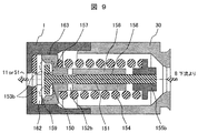
また、実施例3の他の変形例では、図9に示すように環状隙間153bが十分に広く、流体絞り効果を持たない場合にも、ユニット化による組み立て性の向上は期待できる。加えて、圧入部163により、ハウジング156がポンプボディ1に固定される構造とすることで、結果的にガイド部158がポンプボディ1に対して強固に固定される。これにより、弁体の径方向への偏芯を抑制し、安定して高い開放性能を得ることができる。
実施例3の場合にも、リリーフ通路内に形成された筒状の壁部がハウジング156であり、壁部内を摺動し前記弁体と一体位に形成されたガイド部がガイド部158に対応する。
以上のような構成とすることで、高圧化時にも容積効率を維持しつつ、安定して高い開放特性を発揮するリリーフ弁を、小型で安価な構造により実現することが可能である。
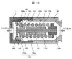
図10は、本発明の実施例4に係るリリーフ弁の断面図を示す。図10において、1はポンプボディ、150はシート部、152bは縦穴通路、153aは貫通穴、154は戻しばね、155bは固定子、156はハウジング、157は弁座部、158aおよび158bはガイド部、159はストッパ、s60は中間室、161は受圧面、162はスリットを、それぞれ表している。
本実施例4では、実施例3で一箇所であったガイド部158を158aと158bの二箇所に分けて配置している。ガイド箇所が増加することにより、弁体の径方向への偏芯をより高精度に抑制することが可能である。また、シート部150を通過した燃料は、弁体151に流体通路として設けた貫通穴153aを通過し、開放される。この際、貫通穴153aは実施例1と同様に流体絞り効果を持ち、中間室160に圧力が蓄えられる。これにより、実施例1と同様の原理で、弁体リフトが増大し、高い開放特性を得ることができる。本実施例における弁体151の形状では、戻しばね154の付勢力をシート部150よりも上流側(紙面右側)の固定子155bで受けるため、貫通穴153aを設けるためのスペースを十分に確保しやすく、また、貫通距離も短いため加工コストの増加を抑えることができる。
実施例4の場合にも、リリーフ通路内に形成された筒状の壁部がハウジング156であり、壁部内を摺動し前記弁体と一体位に形成されたガイド部がガイド部158に対応する。
以上のような構成とすることで、実施例3の場合と同様に高圧化時にも容積効率を維持しつつ、より安定した高い開放特性を発揮するリリーフ弁を、小型で安価な構造により実現することが可能である。
なお上記実施例を通じて、流体通路の断面積について弁体が全開状態におけるシート部の開口面積よりも小さくすることで流体絞りを実現している。
以上のように構成した本発明の実施例によれば、以下の効果を奏する。
弁体の一部で形成された流体絞りで発生する差圧に応じて、弁体に開弁方向の差圧力が発生し、開弁リフトを増加させて、高い開放性能を得ることができる。
弁体をガイドすることで、弁体の一部を含む流体絞りの断面積変化を、最小限に抑えることができる。これにより、流体絞り前後で発生する差圧が変動することを防止することができ、差圧力を安定させることができる。そして、弁体挙動および開放特性を安定化することができる。
また、ガイド部を戻しばねの内側に配置することで、空間を有効に活用することができ、小型化を実現することができる。流体絞りの一部を形成するハウジングに、シート部およびガイド部を一体形成することで、別体形成した場合に比べて、隙間幅などの公差管理が容易になる。これにより、流体絞りの断面積変化を、安価に低減することが可能であり、開放特性を安定化することができる。
さらに、弁体の移動を規制するストッパにより、弁体リフトが増大した際にも、戻しばねの線間で流れが閉鎖されるのを防止することができ、安定した開放特性を得ることができる。ストッパをポンプボディとは別に、熱処理材等で形成することで耐摩耗性を向上させ、長期動作時にも安定した開放特性を得ることができる。
流体絞りは環状隙間や貫通穴等で形成することが可能であり、配置場所に合わせて種類を柔軟に選択することが可能である。これにより、無駄空間を活用でき、小型化を実現することができる。さらに、組み立て時には、ポンプボディの外で、一旦ユニットとして組み上げる構成としてもよい。こうすることで、組み立て性を向上させることができ、量産コストを低減することができる。
本発明は、内燃機関の高圧燃料供給ポンプに限らず、各種の高圧ポンプに広く利用可能である。
1:ボディ
2:プランジャ
3:リテーナ
4:戻しばね
5:電磁弁
6:タペット
7:カム
8:吐出弁
9:吸入通路
11:加圧室
12:吐出通路
15:リリーフ通路
150:シート部
151:弁体
153a:貫通穴
153b:環状隙間
154:戻しばね
155aおよび155b:固定子
156:ハウジング
157:弁座部
158:ガイド部
159:ストッパ
160:中間室
161:受圧面
162:スリット
53:コモンレール
54:インジェクタ
56:圧力センサ
2:プランジャ
3:リテーナ
4:戻しばね
5:電磁弁
6:タペット
7:カム
8:吐出弁
9:吸入通路
11:加圧室
12:吐出通路
15:リリーフ通路
150:シート部
151:弁体
153a:貫通穴
153b:環状隙間
154:戻しばね
155aおよび155b:固定子
156:ハウジング
157:弁座部
158:ガイド部
159:ストッパ
160:中間室
161:受圧面
162:スリット
53:コモンレール
54:インジェクタ
56:圧力センサ
Claims (14)
- ボディ内に上流側から吸入通路、加圧室、吐出通路が順次形成され、前記吐出通路には燃料の流通方向を制限する吐出弁が配置され、前記吐出弁の上流と下流との間に形成されたリリーフ通路にリリーフ弁が配置された高圧燃料供給ポンプであって、
前記リリーフ弁は、弁体が弁座部と接触することで燃料をシールするシート部と、前記弁体の一部を含んで流体絞りを形成する流体通路と、前記弁体と一体に形成されたガイド部と、前記ガイド部を摺動可能に保持するとともに前記弁体の径方向への偏芯を抑制する筒状の壁部と、を有することを特徴とする高圧燃料供給ポンプ。 - 請求項1に記載の高圧燃料供給ポンプであって、
前記流体絞りを形成する前記流体通路は、当該流体通路の断面積が前記弁体が全開状態における前記シート部の開口面積よりも小さくなるように、形成されることを特徴とする高圧燃料供給ポンプ。 - 請求項1または請求項2のいずれかに記載の高圧燃料供給ポンプであって、
前記弁体を前記弁座部に付勢する戻しばねが設けられており、
前記ガイド部は、前記戻しばねの内径側に配置されることを特徴とする高圧燃料供給ポンプ。 - 請求項1ないし3のいずれかに記載の高圧燃料供給ポンプであって、
前記流体絞りは、前記リリーフ弁の部品を収納するハウジングと前記弁体の一部との隙間により形成されており、
前記ハウジングには、前記シート部および前記壁部が一体形成されていることを特徴とする高圧燃料供給ポンプ。 - 請求項1ないし4のいずれかに記載の高圧燃料供給ポンプであって、
前記弁体を前記弁座部に付勢する戻しばねが設けられており、
前記弁体が開弁方向に移動した際、前記戻しばねの線間が密着する前に前記弁体の移動を規制するようストッパが設けられていることを特徴とする高圧燃料供給ポンプ。 - 請求項5に記載の高圧燃料供給ポンプであって、
前記ストッパは、前記戻しばねの付勢力を受ける部材で形成されることを特徴とする高圧燃料供給ポンプ。 - 請求項5に記載の高圧燃料供給ポンプであって、
前記ストッパは、前記ボディに直接形成されることを特徴とする高圧燃料供給ポンプ。 - 請求項5に記載の高圧燃料供給ポンプであって、
前記ストッパは、前記ボディとは別部材で形成され、
前記別部材は熱処理および表面処理が施されていることを特徴とする高圧燃料供給ポンプ。 - 請求項1ないし8のいずれかに記載の高圧燃料供給ポンプであって、
前記流体絞りを形成する前記流体通路は、前記弁体を貫通する貫通穴であることを特徴とする高圧燃料供給ポンプ。 - 請求項1ないし8のいずれかに記載の高圧燃料供給ポンプであって、
前記流体絞りを形成する前記流体通路は、前記弁体の側面に形成されることを特徴とする高圧燃料供給ポンプ。 - 請求項1ないし10のいずれかに記載の高圧燃料供給ポンプであって、
前記リリーフ弁は、前記弁体を前記弁座部に付勢する戻しばねと、当該リリーフ弁の部品を収納するハウジングと、を有し、
前記リリーフ弁は、前記ハウジングに前記弁体を挿入するとともに、前記戻しばねを嵌合し、固定子で固定することでユニット化され、
前記ユニット化された前記リリーフ弁は、前記ボディに固定して組み立てられることを特徴とする高圧燃料供給ポンプ。 - 請求項1または2のいずれかに記載の高圧燃料供給ポンプであって、
前記筒状の壁部は、前記ボディに形成された前記リリーフ通路の内壁または前記リリーフ通路に形成されたハウジングであることを特徴とする高圧燃料供給ポンプ。 - 請求項1または2のいずれかに記載の高圧燃料供給ポンプであって、
前記筒状の壁部は、前記リリーフ通路内に形成された中空の内筒であることを特徴とする高圧燃料供給ポンプ。 - ボディ内に上流側から吸入通路、加圧室、吐出通路が順次形成され、前記吐出通路には燃料の流通方向を制限する吐出弁が配置され、前記吐出弁の上流と下流との間に形成されたリリーフ通路にリリーフ弁が配置された高圧燃料供給ポンプであって、
前記リリーフ弁は、前記吐出弁の上流側に配置された弁体及び弁座部と、前記弁体と一体に形成されたガイド部と、前記ガイド部を摺動可能に保持するとともに前記吐出弁の下流側に向けて固定される筒状の壁部と、前記ガイド部の端部に設けられた固定子と、前記吐出弁の上流側の固定部と前記固定子との間に配置された戻しばねと、を有することを特徴とする高圧燃料供給ポンプ。
Applications Claiming Priority (2)
| Application Number | Priority Date | Filing Date | Title |
|---|---|---|---|
| JP2014-188640 | 2014-09-17 | ||
| JP2014188640A JP6308921B2 (ja) | 2014-09-17 | 2014-09-17 | 高圧燃料供給ポンプ |
Publications (1)
| Publication Number | Publication Date |
|---|---|
| WO2016042895A1 true WO2016042895A1 (ja) | 2016-03-24 |
Family
ID=55532940
Family Applications (1)
| Application Number | Title | Priority Date | Filing Date |
|---|---|---|---|
| PCT/JP2015/069815 Ceased WO2016042895A1 (ja) | 2014-09-17 | 2015-07-10 | 高圧燃料供給ポンプ |
Country Status (2)
| Country | Link |
|---|---|
| JP (1) | JP6308921B2 (ja) |
| WO (1) | WO2016042895A1 (ja) |
Cited By (4)
| Publication number | Priority date | Publication date | Assignee | Title |
|---|---|---|---|---|
| GB2569453A (en) * | 2017-11-30 | 2019-06-19 | Sensata Technologies Inc | In-line fluid pressure regulator |
| CN110552827A (zh) * | 2018-06-04 | 2019-12-10 | 罗伯特·博世有限公司 | 用于高压油泵的进油阀和相应的高压油泵 |
| CN111396222A (zh) * | 2020-04-30 | 2020-07-10 | 北油电控燃油喷射系统(天津)有限公司 | 一种可调节压力和流量的高压共轨用输油泵 |
| WO2023222527A1 (en) * | 2022-05-16 | 2023-11-23 | Delphi Technologies Ip Limited | Fuel pump |
Families Citing this family (3)
| Publication number | Priority date | Publication date | Assignee | Title |
|---|---|---|---|---|
| JP6697552B2 (ja) * | 2016-07-13 | 2020-05-20 | 日立オートモティブシステムズ株式会社 | 高圧燃料供給ポンプ |
| JP6689153B2 (ja) * | 2016-07-22 | 2020-04-28 | 日立オートモティブシステムズ株式会社 | 燃料供給ポンプ |
| DE112018005601B4 (de) | 2017-11-30 | 2026-04-30 | Hitachi Astemo, Ltd. | Hochdruck-kraftstoffzufuhrpumpe |
Citations (4)
| Publication number | Priority date | Publication date | Assignee | Title |
|---|---|---|---|---|
| JP2002515565A (ja) * | 1998-05-20 | 2002-05-28 | ローベルト ボツシユ ゲゼルシヤフト ミツト ベシユレンクテル ハフツング | 圧力制限弁 |
| JP2003301955A (ja) * | 2002-04-12 | 2003-10-24 | Yanmar Co Ltd | 油圧式無段変速機のチェック・リリーフバルブ |
| JP2012158987A (ja) * | 2011-01-28 | 2012-08-23 | Denso Corp | 高圧ポンプ |
| JP2012211598A (ja) * | 2010-06-29 | 2012-11-01 | Denso Corp | 高圧ポンプ |
-
2014
- 2014-09-17 JP JP2014188640A patent/JP6308921B2/ja not_active Expired - Fee Related
-
2015
- 2015-07-10 WO PCT/JP2015/069815 patent/WO2016042895A1/ja not_active Ceased
Patent Citations (4)
| Publication number | Priority date | Publication date | Assignee | Title |
|---|---|---|---|---|
| JP2002515565A (ja) * | 1998-05-20 | 2002-05-28 | ローベルト ボツシユ ゲゼルシヤフト ミツト ベシユレンクテル ハフツング | 圧力制限弁 |
| JP2003301955A (ja) * | 2002-04-12 | 2003-10-24 | Yanmar Co Ltd | 油圧式無段変速機のチェック・リリーフバルブ |
| JP2012211598A (ja) * | 2010-06-29 | 2012-11-01 | Denso Corp | 高圧ポンプ |
| JP2012158987A (ja) * | 2011-01-28 | 2012-08-23 | Denso Corp | 高圧ポンプ |
Cited By (5)
| Publication number | Priority date | Publication date | Assignee | Title |
|---|---|---|---|---|
| GB2569453A (en) * | 2017-11-30 | 2019-06-19 | Sensata Technologies Inc | In-line fluid pressure regulator |
| US10400911B2 (en) | 2017-11-30 | 2019-09-03 | Sensata Technologies, Inc. | In-line fluid pressure regulator |
| CN110552827A (zh) * | 2018-06-04 | 2019-12-10 | 罗伯特·博世有限公司 | 用于高压油泵的进油阀和相应的高压油泵 |
| CN111396222A (zh) * | 2020-04-30 | 2020-07-10 | 北油电控燃油喷射系统(天津)有限公司 | 一种可调节压力和流量的高压共轨用输油泵 |
| WO2023222527A1 (en) * | 2022-05-16 | 2023-11-23 | Delphi Technologies Ip Limited | Fuel pump |
Also Published As
| Publication number | Publication date |
|---|---|
| JP6308921B2 (ja) | 2018-04-11 |
| JP2016061196A (ja) | 2016-04-25 |
Similar Documents
| Publication | Publication Date | Title |
|---|---|---|
| JP6308921B2 (ja) | 高圧燃料供給ポンプ | |
| JP4413260B2 (ja) | 高圧燃料ポンプ | |
| JP5136919B2 (ja) | 高圧ポンプ | |
| US20150078922A1 (en) | High pressure pump | |
| JP2012031840A (ja) | リリーフ弁及びこれを用いた高圧ポンプ | |
| WO2011108131A1 (ja) | 電磁式の流量制御弁及びそれを用いた高圧燃料供給ポンプ | |
| JP5472395B2 (ja) | 高圧ポンプ | |
| CN111271200A (zh) | 燃料泵及其入口阀组件 | |
| US9890753B2 (en) | High-pressure fuel supply pump | |
| JP2012229668A (ja) | 定残圧弁 | |
| JP6689178B2 (ja) | 高圧燃料供給ポンプ | |
| US11781513B2 (en) | Discharge valve mechanism and high-pressure fuel supply pump including the same | |
| JP7198363B2 (ja) | 電磁吸入弁及び高圧燃料供給ポンプ | |
| JP5176947B2 (ja) | 高圧ポンプ | |
| US8608456B2 (en) | High pressure pump | |
| JP6649483B2 (ja) | 高圧燃料供給ポンプ | |
| JP6897173B2 (ja) | 高圧ポンプ | |
| JP6384461B2 (ja) | リリーフ弁装置、及び、それを用いる高圧ポンプ | |
| JP2004132373A (ja) | 特に内燃機関の燃料噴射装置のための通流調整装置 | |
| JP2020133490A (ja) | 高圧燃料供給ポンプ及びリリーフ弁機構 | |
| JP6689153B2 (ja) | 燃料供給ポンプ | |
| JPWO2018221158A1 (ja) | 高圧燃料供給ポンプ | |
| JP2012255450A (ja) | 高圧ポンプ | |
| JP7024071B2 (ja) | 燃料供給ポンプ | |
| JP7077212B2 (ja) | 高圧燃料ポンプ |
Legal Events
| Date | Code | Title | Description |
|---|---|---|---|
| 121 | Ep: the epo has been informed by wipo that ep was designated in this application |
Ref document number: 15842192 Country of ref document: EP Kind code of ref document: A1 |
|
| NENP | Non-entry into the national phase |
Ref country code: DE |
|
| 122 | Ep: pct application non-entry in european phase |
Ref document number: 15842192 Country of ref document: EP Kind code of ref document: A1 |