WO2016042756A1 - クラッチ制御装置 - Google Patents
クラッチ制御装置 Download PDFInfo
- Publication number
- WO2016042756A1 WO2016042756A1 PCT/JP2015/004687 JP2015004687W WO2016042756A1 WO 2016042756 A1 WO2016042756 A1 WO 2016042756A1 JP 2015004687 W JP2015004687 W JP 2015004687W WO 2016042756 A1 WO2016042756 A1 WO 2016042756A1
- Authority
- WO
- WIPO (PCT)
- Prior art keywords
- clutch
- vehicle
- heat generation
- generation state
- driver
- Prior art date
- Legal status (The legal status is an assumption and is not a legal conclusion. Google has not performed a legal analysis and makes no representation as to the accuracy of the status listed.)
- Ceased
Links
Images



Classifications
-
- F—MECHANICAL ENGINEERING; LIGHTING; HEATING; WEAPONS; BLASTING
- F16—ENGINEERING ELEMENTS AND UNITS; GENERAL MEASURES FOR PRODUCING AND MAINTAINING EFFECTIVE FUNCTIONING OF MACHINES OR INSTALLATIONS; THERMAL INSULATION IN GENERAL
- F16D—COUPLINGS FOR TRANSMITTING ROTATION; CLUTCHES; BRAKES
- F16D48/00—External control of clutches
- F16D48/02—Control by fluid pressure
Definitions
- the present invention relates to a clutch control device that performs torque control for notifying a driver that a clutch is in a heat generation state.
- the vehicle is equipped with an automatic transmission that transmits the rotation of the engine.
- an automatic transmission is provided with a transmission mechanism as a rotation transmission mechanism, and the transmission mechanism is provided with a clutch for connecting / disconnecting the rotation transmitted from the engine.
- An object of the present invention is to provide a clutch control device capable of preventing a decrease in drivability.
- One aspect of the present invention is a clutch control device, which includes a clutch heat generation state determination unit that determines whether or not the clutch is in a heat generation state based on a vehicle signal obtained from the vehicle, and a vehicle Based on the signal, the avoidance operation determination unit that determines whether or not the driver of the vehicle is performing a driving operation for avoiding the heat generation state of the clutch, and the driver by varying the torque transmitted to the vehicle with a predetermined variation pattern
- a torque control unit that performs torque control to notify that the clutch is in a heat generation state, and the torque control unit performs a driving operation for avoiding the heat generation state of the clutch when the clutch is in a heat generation state.
- torque control for changing the transmission torque of the vehicle is started and the clutch is not in a heat generation state or the driver If it is determined that performing a driving operation for avoiding the heat generation state of the ends of the torque control to vary the torque transmitted to the vehicle.
- FIG. 1 is a diagram showing a configuration of a clutch control device according to an embodiment of the present invention.
- FIG. 2 is an explanatory diagram of a variation pattern of torque control in the embodiment of the present invention.
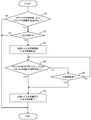
- FIG. 3 is a flowchart showing a flow of operation of the clutch control device according to the embodiment of the present invention.
- FIG. 4 is an explanatory diagram of torque control in another embodiment.
- the clutch control device of the present invention includes a clutch heat generation state determination unit that determines whether or not the clutch is in a heat generation state based on a vehicle signal obtained from the vehicle, and a vehicle driver that generates heat of the clutch based on the vehicle signal.
- An avoidance operation determination unit that determines whether or not a driving operation for avoiding a state is performed, and torque control that informs the driver that the clutch is in a heat generation state by changing the transmission torque to the vehicle with a predetermined fluctuation pattern
- a torque control unit that performs the operation of the vehicle when it is determined that the clutch is in a heat generation state and the driver does not perform a driving operation to avoid the heat generation state of the clutch.
- Torque control that fluctuates the transmission torque is started and the clutch is not in a heat generation state or the driver performs a driving operation to avoid the heat generation state of the clutch. If it is determined that terminates the torque control to vary the torque transmitted to the vehicle.
- the transmission torque is set to a predetermined value. Torque control is performed to vary the variation pattern. Thereby, the driver can be informed that the clutch is in a heat-generating state by changing the torque transmitted to the vehicle in an intentional change pattern that is not natural shaking. Further, based on a vehicle signal obtained from the vehicle, if it is determined that the clutch is not in a heat generation state or the driver is performing a driving operation to avoid the heat generation state of the clutch, torque control that varies the transmission torque End. As a result, the torque control for changing the transmission torque is performed (notifying the driver that the clutch is in a heat generation state) even though the driver is operating to avoid the heat generation state of the clutch. It is possible to prevent the decrease in drivability.
- the torque control unit is fixed when it is determined that the clutch is in a heat generation state and the driver does not perform a driving operation for avoiding the heat generation state of the clutch.
- the transmission torque to the vehicle may be changed with a constant fluctuation pattern with an increased amplitude.
- the amplitude is changed after the transmission torque is changed in a certain fluctuation pattern.
- the transmission torque is varied with a constant variation pattern in which is increased.
- the avoidance operation determination unit determines that the driver is engaged in the clutch when the accelerator opening is determined to be larger than the predetermined reference opening based on the accelerator opening signal obtained from the vehicle. It may be determined that the driving operation for avoiding the heat generation state is being performed.
- torque control for notifying the driver that the clutch is in a heat generating state by changing the transmission torque can be properly terminated, and a decrease in drivability can be prevented.
- FIG. 1 is a diagram showing a configuration of the clutch control device of the present embodiment.
- the vehicle is equipped with an automatic transmission 2 to which the rotational driving force output from the engine 1 is transmitted.
- the automatic transmission 2 is provided with a clutch 3 for disconnecting / connecting the rotational driving force of the engine 1, a transmission 4 having a plurality of transmission gears, and a control device 5 for controlling the operation of the clutch 3.
- the rotational driving force output from the automatic transmission 2 is distributed and transmitted to the left and right wheels 7 via the differential gear device 6.
- the control device 5 includes a vehicle signal acquisition unit 8, a clutch heat generation state determination unit 9, an avoidance operation determination unit 10, and a torque control unit 11.
- the vehicle signal acquisition unit 8 has a function of acquiring various vehicle signals from the vehicle.
- the vehicle signal acquisition unit 8 includes a clutch temperature signal indicating the temperature of the clutch 3, an engine speed signal indicating the engine speed, an input speed signal indicating the input speed, an accelerator position signal indicating the accelerator position, a brake A brake pressure signal indicating pressure, a parking brake signal indicating ON / OFF of the parking brake, an acceleration signal indicating vehicle acceleration, and a vehicle speed signal indicating vehicle speed can be acquired as vehicle signals.
- the vehicle signal acquisition unit 8 may estimate the clutch temperature from the engine speed, the difference between the engine speed and the input speed, the clutch torque, and the like. Further, the slope (rate of change) of the accelerator opening may be estimated from the accelerator opening.
- the clutch heat generation state determination unit 9 has a function of determining whether or not the clutch 3 is in a heat generation state based on the vehicle signal obtained by the vehicle signal acquisition unit 8.
- the clutch heat generation state determination unit 9 determines that the clutch 3 is in a heat generation state when all of the following determination conditions (1) to (4) are satisfied.
- a certain time for example, 5 seconds
- the clutch temperature is equal to or higher than a predetermined reference temperature (for example, 350 ° C., which can be appropriately set within the range of 250 to 400 ° C.).
- the engine speed is not less than a predetermined reference speed (for example, 1000 rpm).
- the difference between the engine speed and the input speed is equal to or greater than a predetermined reference speed difference (for example, 300 rpm at which a half-clutch state is established).
- the clutch heat generation state determination unit 9 determines that the clutch 3 is in a heat generation state when it is determined that the temperature of the clutch 3 is equal to or higher than a predetermined reference temperature based on a clutch temperature signal obtained from the vehicle. .
- the avoidance operation determination unit 10 has a function of determining whether or not the driver is performing a driving operation for avoiding the heat generation state of the clutch 3 based on the vehicle signal obtained by the vehicle signal acquisition unit 8.
- the avoidance operation determination unit 10 performs an operation for the driver to avoid the heat generation state of the clutch 3 when one of the following determination conditions (5) to (8) is not satisfied.
- the accelerator opening is equal to or less than a predetermined reference opening (for example, 60%).
- the change amount of the accelerator opening is equal to or less than a predetermined reference change amount (for example, 7%, which can be appropriately set within a range of 5 to 10%), or the change amount of the brake pressure is a predetermined reference change amount ( For example, on / off change) or below, or the parking brake has not changed (keep on / off).
- the acceleration of the vehicle is not more than a predetermined reference acceleration (for example, 0.1 to 1.0 m / sec 2 ).
- the vehicle speed is equal to or lower than a predetermined reference speed (for example, 10 km / hour).
- the avoidance operation determination unit 10 causes the driver to avoid the heat generation state of the clutch 3 when it is determined that the accelerator opening is not equal to or less than a predetermined reference opening based on the accelerator opening signal obtained from the vehicle. It is determined that the driving operation is being performed.
- FIG. 2 is a diagram showing an example of a variation pattern of torque control.
- the torque control unit 11 first changes the torque transmitted to the vehicle with the fluctuation pattern of the amplitude W1 when the time t1 is reached. (First phase). Next, at time t2, torque control is performed to vary the torque transmitted to the vehicle with a larger variation pattern of amplitude W2 (second phase). Thereafter, the torque control for changing the transmission torque to the vehicle with the fluctuation pattern of the amplitude W2 is repeated.
- the waveform of the fluctuation pattern is, for example, two sin waves.
- the torque control unit 11 ends the torque control for changing the torque transmitted to the vehicle. .
- the determination conditions (1) to (4) by the clutch heat generation state determination unit 9 and the determination condition (5) by the avoidance operation determination unit 10 It is determined whether or not all of (8) to (8) are satisfied, that is, whether or not the clutch 3 is in a heat generation state and the driver is not performing an operation to avoid the heat generation state of the clutch 3 (S1).
- the determination conditions (1) to (4) and the determination conditions (5) to (8) are all satisfied, when a certain time (for example, 5 seconds) elapses in that state (S2), the transmission torque is reduced.
- the torque control to be changed is started (S3).
- the torque control for notifying the driver that the clutch 3 is in the heat generation state by changing the transmission torque can be appropriately terminated, and the drivability is reduced. Can be prevented.
- the clutch 3 based on the vehicle signal obtained from the vehicle, it is determined that the clutch 3 is in a heat generation state and that the driver is not performing a driving operation for avoiding the heat generation state of the clutch 3. Then, torque control for changing the transmission torque with a predetermined fluctuation pattern is performed. Thereby, the driver can be informed that the clutch 3 is in a heat generation state by changing the torque transmitted to the vehicle in an intentional change pattern that is not a natural vibration.
- a torque that fluctuates the transmission torque is performed to vary the transmission torque even though the driver is operating to avoid the heat generation state of the clutch 3 (notifying the driver that the clutch 3 is in a heat generation state). Can be prevented, and a decrease in drivability can be prevented.
- the transmission torque is changed with a constant fluctuation pattern, and then the transmission torque is changed with a constant fluctuation pattern with an increased amplitude.
- the accelerator when the accelerator is sufficiently depressed, it is determined that the driver is operating to avoid the heat generation state of the clutch 3, and the torque control for changing the transmission torque is ended. Is done.
- torque control is performed to vary the transmission torque even though the driver is operating to avoid the heat generation state of the clutch 3 (notifying the driver that the clutch 3 is in a heat generation state). Can be prevented, and a decrease in drivability can be prevented.
- the waveform of the variation pattern is a sine wave
- the waveform of the variation pattern may be a rectangular wave as shown in FIG.
- the number of fluctuation pattern waveforms is not limited to two, and may be three or more.
- an example of a two-stage variation pattern of the first phase and the second phase has been described, but the variation pattern may be a multi-stage of three or more stages.
- the clutch control device can appropriately terminate the torque control informing the driver that the clutch is in a heat-generating state by changing the transmission torque, thereby preventing a decrease in drivability. It has the effect of being able to be applied and is useful when applied to a vehicle or the like equipped with an automatic transmission.
Landscapes
- Engineering & Computer Science (AREA)
- General Engineering & Computer Science (AREA)
- Physics & Mathematics (AREA)
- Fluid Mechanics (AREA)
- Mechanical Engineering (AREA)
- Hydraulic Clutches, Magnetic Clutches, Fluid Clutches, And Fluid Joints (AREA)
- Control Of Driving Devices And Active Controlling Of Vehicle (AREA)
Abstract
クラッチ制御装置は、車両から得られる車両信号に基づいて、クラッチが発熱状態であるか否か、および、ドライバがクラッチの発熱状態を回避するための運転操作をしているか否かを判定する。クラッチが発熱状態であり、ドライバがクラッチの発熱状態を回避するための運転操作を行っていないと判定されると、車両への伝達トルクを所定の変動パターンで変動させて、車両のドライバにクラッチが発熱状態であることを知らせるトルク制御を行う。クラッチが発熱状態でない、または、ドライバがクラッチの発熱状態を回避するための運転操作をしていると判定されると、車両への伝達トルクを変動させるトルク制御を終了する。
Description
本発明は、クラッチが発熱状態であることをドライバに知らせるトルク制御を行うクラッチ制御装置に関する。
一般に、車両には、エンジンの回転が伝達される自動変速機が搭載されている。このような自動変速機には、回転伝達機構としての変速機構とが設けられており、変速機構には、エンジンから伝達された回転を断/接するためのクラッチが設けられている。
このような自動変速機を搭載した車両において、坂路(上り坂)で半クラッチ状態を保持している状態、または、渋滞中に発進/停車を繰り返す状態では、エンジンから自動変速機に至るトルク伝達系で過負荷が生じ、クラッチで発生する発熱量が増加する。極わずかな発熱量でもクラッチの温度は上昇する。クラッチが高温状態になると、クラッチの摩擦特性が変化したり、クラッチの摩耗量が増加してしまうので、その対策が必要となる。
そこで従来、トルク伝達系において過負荷が生じた場合に、車両に振動が生じるように伝達トルクを変動させて、ドライバに注意を喚起する制御装置が提案されている。この従来の制御装置では、エンジン回転数とインプット回転数の差分が閾値を超えると、伝達トルクの変動を終了する(特許文献1参照)。
しかしながら、従来の制御装置においては、ドライバがクラッチの発熱状態を回避するための運転操作をしている場合であっても、エンジン回転数とインプット回転数の差分が閾値を超えない限り、伝達トルクを変動させて車両を振動させるシグナリングが行われ、その結果、ドライバビリティが低下する。
本発明は、上記背景の下でなされたものである。本発明の目的は、ドライバビリティの低下を防ぐことのできるクラッチ制御装置を提供することにある。
本発明の一の態様は、クラッチ制御装置であり、このクラッチ制御装置は、車両から得られる車両信号に基づいて、クラッチが発熱状態であるか否かを判定するクラッチ発熱状態判定部と、車両信号に基づいて、車両のドライバがクラッチの発熱状態を回避するための運転操作を行っているか否かを判定する回避操作判定部と、車両への伝達トルクを所定の変動パターンで変動させてドライバにクラッチが発熱状態であることを知らせるトルク制御を行うトルク制御部と、を備え、トルク制御部は、クラッチが発熱状態であり、かつ、ドライバがクラッチの発熱状態を回避するための運転操作を行っていないと判定された場合に、車両の伝達トルクを変動させるトルク制御を開始し、クラッチが発熱状態でない、または、ドライバがクラッチの発熱状態を回避するための運転操作を行っていると判定された場合に、車両への伝達トルクを変動させるトルク制御を終了する。
以下に説明するように、本発明には他の態様が存在する。したがって、この発明の開示は、本発明の一部の態様の提供を意図しており、ここで記述され請求される発明の範囲を制限することは意図していない。
以下に本発明の詳細な説明を述べる。ただし、以下の詳細な説明と添付の図面は発明を限定するものではない。
本発明のクラッチ制御装置は、車両から得られる車両信号に基づいて、クラッチが発熱状態であるか否かを判定するクラッチ発熱状態判定部と、車両信号に基づいて、車両のドライバがクラッチの発熱状態を回避するための運転操作を行っているか否かを判定する回避操作判定部と、車両への伝達トルクを所定の変動パターンで変動させてドライバにクラッチが発熱状態であることを知らせるトルク制御を行うトルク制御部と、を備え、トルク制御部は、クラッチが発熱状態であり、かつ、ドライバがクラッチの発熱状態を回避するための運転操作を行っていないと判定された場合に、車両の伝達トルクを変動させるトルク制御を開始し、クラッチが発熱状態でない、または、ドライバがクラッチの発熱状態を回避するための運転操作を行っていると判定された場合に、車両への伝達トルクを変動させるトルク制御を終了する。
この構成により、車両から得られる車両信号に基づいて、クラッチが発熱状態であり、かつ、ドライバがクラッチの発熱状態を回避するための運転操作を行っていないと判定されると、伝達トルクを所定の変動パターンで変動させるトルク制御が行われる。これにより、自然な揺れではない意図的な変動パターンで車両への伝達トルクを変動させることによって、ドライバにクラッチが発熱状態であることを知らせることができる。さらに、車両から得られる車両信号に基づいて、クラッチが発熱状態でない、または、ドライバがクラッチの発熱状態を回避するための運転操作をしていると判定されると、伝達トルクを変動させるトルク制御を終了させる。これにより、ドライバがクラッチの発熱状態を回避するための運転操作をしているにも関わらず、伝達トルクを変動させるトルク制御が行われる(ドライバにクラッチが発熱状態であることを知らせる)のを防止することができ、ドライバビリティの低下を防ぐことができる。
また、本発明のクラッチ制御装置では、トルク制御部は、クラッチが発熱状態であり、かつ、ドライバがクラッチの発熱状態を回避するための運転操作を行っていないと判定された場合に、一定の変動パターンで車両への伝達トルクを変動させた後、振幅を増大させた一定の変動パターンで車両への伝達トルクを変動させてもよい。
この構成により、クラッチが発熱状態であり、かつ、ドライバがクラッチの発熱状態を回避するための運転操作を行っていないと判定されると、一定の変動パターンで伝達トルクを変動させた後、振幅を増大させた一定の変動パターンで伝達トルクを変動させる。これにより、車両の急な飛び出しの回避や、ドライバに対する唐突な揺れに対する恐怖感を緩和することができ、自然な揺れではない意図的な変動パターンで車両への伝達トルクを変動させることによって、ドライバにクラッチが発熱状態であることを知らせることができる。
また、本発明のクラッチ制御装置では、回避操作判定部は、車両から得られるアクセル開度信号に基づいて、アクセル開度が所定の基準開度より大きいと判定された場合に、ドライバがクラッチの発熱状態を回避するための運転操作をしていると判定してもよい。
この構成により、アクセルを十分に踏み込んでいる場合には、ドライバがクラッチの発熱状態を回避するための運転操作をしていると判定され、伝達トルクを変動させるトルク制御が終了される。これにより、ドライバがクラッチの発熱状態を回避するための運転操作をしているにも関わらず、伝達トルクを変動させるトルク制御が行われる(ドライバにクラッチが発熱状態であることを知らせる)のを防止することができ、ドライバビリティの低下を防ぐことができる。
本発明によれば、伝達トルクを変動させてドライバにクラッチが発熱状態であることを知らせるトルク制御を適切に終了させることができ、ドライバビリティの低下を防ぐことができる。
(実施の形態)
以下、本発明の実施の形態のクラッチ制御装置について、図面を用いて説明する。本実施の形態では、自動変速機を搭載した車両等に用いられるクラッチ制御装置の場合を例示する。
以下、本発明の実施の形態のクラッチ制御装置について、図面を用いて説明する。本実施の形態では、自動変速機を搭載した車両等に用いられるクラッチ制御装置の場合を例示する。
本発明の実施の形態のクラッチ制御装置の構成を、図面を参照して説明する。図1は、本実施の形態のクラッチ制御装置の構成を示す図である。図1に示すように、車両には、エンジン1から出力された回転駆動力が伝達される自動変速機2が搭載されている。自動変速機2には、エンジン1の回転駆動力を断/接するためのクラッチ3と、複数の変速ギアを備えるトランスミッション4と、クラッチ3の動作を制御する制御装置5が設けられている。自動変速機2から出力された回転駆動力は、デファレンシャルギア装置6を介して、左右の車輪7に分配して伝達される。
制御装置5は、車両信号取得部8と、クラッチ発熱状態判定部9と、回避操作判定部10と、トルク制御部11を備えている。車両信号取得部8は、車両から各種の車両信号を取得する機能を備えている。例えば、車両信号取得部8は、クラッチ3の温度を示すクラッチ温度信号、エンジン回転数を示すエンジン回転数信号、インプット回転数を示すインプット回転数信号、アクセル開度を示すアクセル開度信号、ブレーキ圧を示すブレーキ圧信号、パーキングブレーキのオン/オフを示すパーキングブレーキ信号、車両の加速度を示す加速度信号、車両の速度を示す車速信号を、車両信号として取得することができる。なお、車両信号取得部8は、エンジン回転数、エンジン回転数とインプット回転数の回転数差、クラッチトルク等から、クラッチ温度を推定してもよい。また、アクセル開度からアクセル開度の傾き(変化率)を推定してもよい。
クラッチ発熱状態判定部9は、車両信号取得部8によって得られる車両信号に基づいて、クラッチ3が発熱状態であるか否かを判定する機能を備えている。
この場合、クラッチ発熱状態判定部9は、以下の判定条件(1)~(4)をすべて満たしている場合には、クラッチ3が発熱状態であると判定する。
(1)車両が停車状態から発進しようとしてから一定時間(例えば5秒)経過している。
(2)クラッチ温度が所定の基準温度(例えば350℃。250~400℃の範囲内で適宜設定可能)以上である。
(3)エンジン回転数が所定の基準回転数(例えば1000rpm)以上である。
(4)エンジン回転数とインプット回転数の差が所定の基準回転数差(例えば、半クラッチ状態となる300rpm)以上である。
(1)車両が停車状態から発進しようとしてから一定時間(例えば5秒)経過している。
(2)クラッチ温度が所定の基準温度(例えば350℃。250~400℃の範囲内で適宜設定可能)以上である。
(3)エンジン回転数が所定の基準回転数(例えば1000rpm)以上である。
(4)エンジン回転数とインプット回転数の差が所定の基準回転数差(例えば、半クラッチ状態となる300rpm)以上である。
例えば、クラッチ発熱状態判定部9は、車両から得られるクラッチ温度信号に基づいて、クラッチ3の温度が所定の基準温度以上であると判定された場合に、クラッチ3が発熱状態であると判定する。
回避操作判定部10は、車両信号取得部8によって得られる車両信号に基づいて、ドライバがクラッチ3の発熱状態を回避するための運転操作をしているか否かを判定する機能を備えている。
この場合、回避操作判定部10は、以下の判定条件(5)~(8)のうちの一つが満たされなくなった場合には、ドライバがクラッチ3の発熱状態を回避するための操作を行っていないと判定する。
(5)アクセル開度が所定の基準開度(例えば60%)以下である。
(6)アクセル開度の変化量が所定の基準変化量(例えば7%。5~10%の範囲内で適宜設定可能)以下である、または、ブレーキ圧の変化量が所定の基準変化量(例えばオン/オフの変化)以下である、または、パーキングブレーキが変化していない(オンのまま/オフのまま)。
(7)車両の加速度が所定の基準加速度(例えば0.1~1.0m/sec2)以下である。
(8)車速が所定の基準速度(例えば10km/時)以下である。
(5)アクセル開度が所定の基準開度(例えば60%)以下である。
(6)アクセル開度の変化量が所定の基準変化量(例えば7%。5~10%の範囲内で適宜設定可能)以下である、または、ブレーキ圧の変化量が所定の基準変化量(例えばオン/オフの変化)以下である、または、パーキングブレーキが変化していない(オンのまま/オフのまま)。
(7)車両の加速度が所定の基準加速度(例えば0.1~1.0m/sec2)以下である。
(8)車速が所定の基準速度(例えば10km/時)以下である。
例えば、回避操作判定部10は、車両から得られるアクセル開度信号に基づいて、アクセル開度が所定の基準開度以下でないと判定された場合に、ドライバがクラッチ3の発熱状態を回避するための運転操作をしていると判定する。
トルク制御部11は、クラッチ発熱状態判定部9と回避操作判定部10によって、クラッチ3が発熱状態であり、かつ、ドライバがクラッチ3の発熱状態を回避する操作をしていないと判定された場合に、車両への伝達トルクを一定の変動パターン(自然な揺れではない意図的な変動パターン)で変動させて車両のドライバにクラッチ3が発熱状態であることを知らせるトルク制御を行う機能を備えている。
図2は、トルク制御の変動パターンの一例を示す図である。図2に示すように、トルク制御部11は、クラッチ3が発熱状態であると判定された場合に、まず、時間t1になると、振幅W1の変動パターンで車両への伝達トルクを変動させるトルク制御を行う(第1フェーズ)。つぎに、時間t2になると、より大きい振幅W2の変動パターンで車両への伝達トルクを変動させるトルク制御を行う(第2フェーズ)。これ以降、振幅W2の変動パターンで車両への伝達トルクを変動させるトルク制御を繰り返す。なお、変動パターンの波形は、例えば、二つのsin波である。
トルク制御部11は、回避操作判定部10によってドライバがクラッチ3の発熱状態を回避するための運転操作をしていると判定された場合に、車両への伝達トルクを変動させるトルク制御を終了する。
以上のように構成されたクラッチ制御装置5について、図3のフロー図を参照してその動作を説明する。
図3に示すように、本実施の形態のクラッチ制御装置5では、まず、クラッチ発熱状態判定部9による判定条件(1)~(4)、および、回避操作判定部10による判定条件(5)~(8)がすべて満たされているか否か、すなわち、クラッチ3が発熱状態であり、かつ、ドライバがクラッチ3の発熱状態を回避する操作を行っていないか否かを判定する(S1)。判定条件(1)~(4)および判定条件(5)~(8)がすべて満たされている場合には、その状態のまま一定時間(例えば5秒)が経過すると(S2)、伝達トルクを変動させるトルク制御を開始する(S3)。
トルク制御を開始した後、クラッチ発熱状態判定部9による判定条件(1)~(4)、または、回避操作判定部10による判定条件(5)~(8)のうちの一つが満たされなくなったか否か、すなわち、クラッチ3が発熱状態でない、または、ドライバがクラッチ3の発熱状態を回避するための運転操作をしているか否かを判定する(S4)。判定条件(1)~(4)または判定条件(5)~(8)のうちの一つでも満たされなくなった場合には、クラッチ3が発熱状態でない、または、ドライバがクラッチ3の発熱状態を回避するための運転操作をしていると判定され、伝達トルクを変動させるトルク制御を終了させる(S5)。
一方、判定条件(1)~(4)および判定条件(5)~(8)がすべて満たされている場合、すなわち、クラッチ3が発熱状態であり、かつ、ドライバがクラッチ3の発熱状態を回避するための運転操作をしていないと判定された場合であっても、一定時間(例えば30秒)が経過すると(S6)、伝達トルクを変動させるトルク制御を終了させる(S5)。
このような本実施の形態のクラッチ制御装置5によれば、伝達トルクを変動させてドライバにクラッチ3が発熱状態であることを知らせるトルク制御を適切に終了させることができ、ドライバビリティの低下を防ぐことができる。
すなわち、本実施の形態では、車両から得られる車両信号に基づいて、クラッチ3が発熱状態であり、かつ、ドライバがクラッチ3の発熱状態を回避するための運転操作を行っていないと判定されると、伝達トルクを所定の変動パターンで変動させるトルク制御が行われる。これにより、自然な揺れではない意図的な変動パターンで車両への伝達トルクを変動させることによって、ドライバにクラッチ3が発熱状態であることを知らせることができる。
さらに、車両から得られる車両信号に基づいて、クラッチが発熱状態でない、または、ドライバがクラッチ3の発熱状態を回避するための運転操作をしていると判定されると、伝達トルクを変動させるトルク制御を終了させる。これにより、ドライバがクラッチ3の発熱状態を回避するための運転操作をしているにも関わらず、伝達トルクを変動させるトルク制御が行われる(ドライバにクラッチ3が発熱状態であることを知らせる)のを防止することができ、ドライバビリティの低下を防ぐことができる。
また、本実施の形態では、クラッチ3が発熱状態であると判定されると、一定の変動パターンで伝達トルクを変動させた後、振幅を増大させた一定の変動パターンで伝達トルクを変動させる。これにより、車両の急な飛び出しの回避や、ドライバに対する唐突な揺れに対する恐怖感を緩和することができ、自然な揺れではない意図的な変動パターンで車両への伝達トルクを変動させることによって、ドライバにクラッチ3が発熱状態であることを知らせることができる。
また、本実施の形態では、アクセルを十分に踏み込んでいる場合には、ドライバがクラッチ3の発熱状態を回避するための運転操作をしていると判定され、伝達トルクを変動させるトルク制御が終了される。これにより、ドライバがクラッチ3の発熱状態を回避するための運転操作をしているにも関わらず、伝達トルクを変動させるトルク制御が行われる(ドライバにクラッチ3が発熱状態であることを知らせる)のを防止することができ、ドライバビリティの低下を防ぐことができる。
以上、本発明の実施の形態を例示により説明したが、本発明の範囲はこれらに限定されるものではなく、請求項に記載された範囲内において目的に応じて変更・変形することが可能である。
例えば、図2の説明では、変動パターンの波形をsin波とした例について説明したが、図4に示すように、変動パターンの波形は矩形波であってもよい。また、変動パターンの波形の個数は二つに限られず、三つ以上であってもよい。さらに、図2の説明では、第1フェーズと第2フェーズの二段階の変動パターンの例について説明したが、変動パターンは三段階以上の多段階であってもよい。
以上に現時点で考えられる本発明の好適な実施の形態を説明したが、本実施の形態に対して多様な変形が可能なことが理解され、そして、本発明の真実の精神と範囲内にあるそのようなすべての変形を添付の請求の範囲が含むことが意図されている。
以上のように、本発明にかかるクラッチ制御装置は、伝達トルクを変動させてドライバにクラッチが発熱状態であることを知らせるトルク制御を適切に終了させることができ、ドライバビリティの低下を防ぐことができるという効果を有し、自動変速機を搭載した車両等に適用され、有用である。
1 エンジン(ENG)
2 自動変速機
3 クラッチ
4 トランスミッション(T/M)
5 制御装置(クラッチ制御装置)
6 デファレンシャルギア装置
7 車輪
8 車両信号取得部
9 クラッチ発熱状態判定部
10 回避操作判定部
11 トルク制御部
2 自動変速機
3 クラッチ
4 トランスミッション(T/M)
5 制御装置(クラッチ制御装置)
6 デファレンシャルギア装置
7 車輪
8 車両信号取得部
9 クラッチ発熱状態判定部
10 回避操作判定部
11 トルク制御部
Claims (3)
- 車両から得られる車両信号に基づいて、クラッチが発熱状態であるか否かを判定するクラッチ発熱状態判定部と、
前記車両信号に基づいて、前記車両のドライバが前記クラッチの発熱状態を回避するための運転操作を行っているか否かを判定する回避操作判定部と、
前記車両への伝達トルクを所定の変動パターンで変動させて前記ドライバに前記クラッチが発熱状態であることを知らせるトルク制御を行うトルク制御部と、
を備え、
前記トルク制御部は、
前記クラッチが発熱状態であり、かつ、前記ドライバが前記クラッチの発熱状態を回避するための運転操作を行っていないと判定された場合に、前記車両の伝達トルクを変動させるトルク制御を開始し、
前記クラッチが発熱状態でない、または、前記ドライバが前記クラッチの発熱状態を回避するための運転操作を行っていると判定された場合に、前記車両への伝達トルクを変動させるトルク制御を終了する、クラッチ制御装置。 - 前記トルク制御部は、前記クラッチが発熱状態であり、かつ、前記ドライバが前記クラッチの発熱状態を回避するための運転操作を行っていないと判定された場合に、一定の変動パターンで前記車両への伝達トルクを変動させた後、振幅を増大させた前記一定の変動パターンで前記車両への伝達トルクを変動させる、請求項1に記載のクラッチ制御装置。
- 前記回避操作判定部は、前記車両から得られるアクセル開度信号に基づいて、アクセル開度が所定の基準開度より大きいと判定された場合に、前記ドライバが前記クラッチの発熱状態を回避するための運転操作をしていると判定する、請求項1に記載のクラッチ制御装置。
Priority Applications (1)
| Application Number | Priority Date | Filing Date | Title |
|---|---|---|---|
| CN201580049342.5A CN107076226A (zh) | 2014-09-16 | 2015-09-15 | 离合器控制装置 |
Applications Claiming Priority (2)
| Application Number | Priority Date | Filing Date | Title |
|---|---|---|---|
| JP2014-187522 | 2014-09-16 | ||
| JP2014187522A JP2016061322A (ja) | 2014-09-16 | 2014-09-16 | クラッチ制御装置 |
Publications (1)
| Publication Number | Publication Date |
|---|---|
| WO2016042756A1 true WO2016042756A1 (ja) | 2016-03-24 |
Family
ID=55532812
Family Applications (1)
| Application Number | Title | Priority Date | Filing Date |
|---|---|---|---|
| PCT/JP2015/004687 Ceased WO2016042756A1 (ja) | 2014-09-16 | 2015-09-15 | クラッチ制御装置 |
Country Status (3)
| Country | Link |
|---|---|
| JP (1) | JP2016061322A (ja) |
| CN (1) | CN107076226A (ja) |
| WO (1) | WO2016042756A1 (ja) |
Cited By (1)
| Publication number | Priority date | Publication date | Assignee | Title |
|---|---|---|---|---|
| US12434750B2 (en) | 2021-02-02 | 2025-10-07 | Faiveley Transport Italia S.P.A. | Monitoring system for a plurality of homogeneous devices of at least two convoys, in particular two railway convoys |
Citations (3)
| Publication number | Priority date | Publication date | Assignee | Title |
|---|---|---|---|---|
| JPH08230503A (ja) * | 1995-01-28 | 1996-09-10 | Luk Getriebe Syst Gmbh | トルク伝達系の制御装置および制御方法 |
| JP2010228511A (ja) * | 2009-03-26 | 2010-10-14 | Nissan Motor Co Ltd | ハイブリッド車両の駆動力制御装置 |
| JP2012087911A (ja) * | 2010-10-22 | 2012-05-10 | Nissan Motor Co Ltd | 車両用制御装置 |
Family Cites Families (3)
| Publication number | Priority date | Publication date | Assignee | Title |
|---|---|---|---|---|
| JPH11247898A (ja) * | 1998-02-26 | 1999-09-14 | Isuzu Motors Ltd | オートクラッチを備えた車両の半クラッチ警報装置 |
| GB2380533B (en) * | 2000-02-24 | 2004-06-09 | Luk Lamellen & Kupplungsbau | Device and method for automatically actuating a clutch |
| JP2008057670A (ja) * | 2006-08-31 | 2008-03-13 | F C C:Kk | クラッチの発熱量推定装置 |
-
2014
- 2014-09-16 JP JP2014187522A patent/JP2016061322A/ja active Pending
-
2015
- 2015-09-15 WO PCT/JP2015/004687 patent/WO2016042756A1/ja not_active Ceased
- 2015-09-15 CN CN201580049342.5A patent/CN107076226A/zh active Pending
Patent Citations (3)
| Publication number | Priority date | Publication date | Assignee | Title |
|---|---|---|---|---|
| JPH08230503A (ja) * | 1995-01-28 | 1996-09-10 | Luk Getriebe Syst Gmbh | トルク伝達系の制御装置および制御方法 |
| JP2010228511A (ja) * | 2009-03-26 | 2010-10-14 | Nissan Motor Co Ltd | ハイブリッド車両の駆動力制御装置 |
| JP2012087911A (ja) * | 2010-10-22 | 2012-05-10 | Nissan Motor Co Ltd | 車両用制御装置 |
Cited By (1)
| Publication number | Priority date | Publication date | Assignee | Title |
|---|---|---|---|---|
| US12434750B2 (en) | 2021-02-02 | 2025-10-07 | Faiveley Transport Italia S.P.A. | Monitoring system for a plurality of homogeneous devices of at least two convoys, in particular two railway convoys |
Also Published As
| Publication number | Publication date |
|---|---|
| CN107076226A (zh) | 2017-08-18 |
| JP2016061322A (ja) | 2016-04-25 |
Similar Documents
| Publication | Publication Date | Title |
|---|---|---|
| KR20100029813A (ko) | 차량 클러치의 슬립을 제어하기 위한 방법 및 장치 | |
| US9470279B2 (en) | Dry clutch control method for vehicle | |
| CN105000017B (zh) | 车辆控制设备 | |
| WO2013145985A1 (ja) | 車両の発進制御装置及び発進制御方法 | |
| RU2012114782A (ru) | Способ и устройство для определения точки контакта сцепления в транспортном средстве | |
| MY188635A (en) | Vehicle lock-up control method and control device | |
| WO2019110880A1 (fr) | Procede de detection d'un etat de glissement d'embrayage pour un vehicule automobile | |
| CN105508464A (zh) | 控制商用车辆的自动离合器的方法及自动离合器的控制器 | |
| CN110114681A (zh) | 检测可旋转轴的旋转方向变化的方法 | |
| JP2016061322A (ja) | クラッチ制御装置 | |
| US11293501B2 (en) | Powertrain for a vehicle and method for controlling a powertrain in a vehicle | |
| KR20120052272A (ko) | 자동차의 크리핑 과정 제어 방법 | |
| JP2009062898A (ja) | 車両走行制御装置 | |
| EP3187744B1 (en) | Vehicle lockup clutch control device | |
| CN104235343B (zh) | 离合器踏板的转矩限制方法和系统 | |
| JP6071918B2 (ja) | 無段変速機の制御装置 | |
| JP2005299927A (ja) | 自動化された伝動装置のクラッチのクラッチトルクを制御する方法および装置 | |
| EP2663783B1 (en) | Method and clutch actuator control unit for controlling the torque transfer on a power train for a vehicle | |
| CN108437994B (zh) | 用于在运动模式中运行车辆的驱动系统的方法 | |
| CN108068623B (zh) | 用于车辆的牵引控制方法和装置 | |
| JP5065947B2 (ja) | 駆動系制御装置 | |
| JP6447428B2 (ja) | 車両用制御装置 | |
| JP2016141164A (ja) | 車両制御装置 | |
| CN106163894A (zh) | 在用于驱动系统的驱动源之间具有优化式切换的同步化附件装置驱动系统 | |
| JP2019152308A (ja) | 制動力制御装置 |
Legal Events
| Date | Code | Title | Description |
|---|---|---|---|
| 121 | Ep: the epo has been informed by wipo that ep was designated in this application |
Ref document number: 15841867 Country of ref document: EP Kind code of ref document: A1 |
|
| NENP | Non-entry into the national phase |
Ref country code: DE |
|
| 122 | Ep: pct application non-entry in european phase |
Ref document number: 15841867 Country of ref document: EP Kind code of ref document: A1 |