WO2016042618A1 - 気液分離器及び超臨界流体装置 - Google Patents
気液分離器及び超臨界流体装置 Download PDFInfo
- Publication number
- WO2016042618A1 WO2016042618A1 PCT/JP2014/074539 JP2014074539W WO2016042618A1 WO 2016042618 A1 WO2016042618 A1 WO 2016042618A1 JP 2014074539 W JP2014074539 W JP 2014074539W WO 2016042618 A1 WO2016042618 A1 WO 2016042618A1
- Authority
- WO
- WIPO (PCT)
- Prior art keywords
- gas
- liquid
- liquid separator
- discharge
- mobile phase
- Prior art date
- Legal status (The legal status is an assumption and is not a legal conclusion. Google has not performed a legal analysis and makes no representation as to the accuracy of the status listed.)
- Ceased
Links
Images








Classifications
-
- G—PHYSICS
- G01—MEASURING; TESTING
- G01N—INVESTIGATING OR ANALYSING MATERIALS BY DETERMINING THEIR CHEMICAL OR PHYSICAL PROPERTIES
- G01N30/00—Investigating or analysing materials by separation into components using adsorption, absorption or similar phenomena or using ion-exchange, e.g. chromatography or field flow fractionation
- G01N30/02—Column chromatography
- G01N30/80—Fraction collectors
-
- B—PERFORMING OPERATIONS; TRANSPORTING
- B01—PHYSICAL OR CHEMICAL PROCESSES OR APPARATUS IN GENERAL
- B01D—SEPARATION
- B01D19/00—Degasification of liquids
-
- B—PERFORMING OPERATIONS; TRANSPORTING
- B01—PHYSICAL OR CHEMICAL PROCESSES OR APPARATUS IN GENERAL
- B01D—SEPARATION
- B01D19/00—Degasification of liquids
- B01D19/0005—Degasification of liquids with one or more auxiliary substances
-
- B—PERFORMING OPERATIONS; TRANSPORTING
- B01—PHYSICAL OR CHEMICAL PROCESSES OR APPARATUS IN GENERAL
- B01D—SEPARATION
- B01D19/00—Degasification of liquids
- B01D19/0042—Degasification of liquids modifying the liquid flow
-
- G—PHYSICS
- G01—MEASURING; TESTING
- G01N—INVESTIGATING OR ANALYSING MATERIALS BY DETERMINING THEIR CHEMICAL OR PHYSICAL PROPERTIES
- G01N1/00—Sampling; Preparing specimens for investigation
- G01N1/28—Preparing specimens for investigation including physical details of (bio-)chemical methods covered elsewhere, e.g. G01N33/50, C12Q
- G01N1/40—Concentrating samples
- G01N1/4055—Concentrating samples by solubility techniques
-
- G—PHYSICS
- G01—MEASURING; TESTING
- G01N—INVESTIGATING OR ANALYSING MATERIALS BY DETERMINING THEIR CHEMICAL OR PHYSICAL PROPERTIES
- G01N30/00—Investigating or analysing materials by separation into components using adsorption, absorption or similar phenomena or using ion-exchange, e.g. chromatography or field flow fractionation
- G01N30/02—Column chromatography
-
- B—PERFORMING OPERATIONS; TRANSPORTING
- B01—PHYSICAL OR CHEMICAL PROCESSES OR APPARATUS IN GENERAL
- B01D—SEPARATION
- B01D15/00—Separating processes involving the treatment of liquids with solid sorbents; Apparatus therefor
- B01D15/08—Selective adsorption, e.g. chromatography
- B01D15/26—Selective adsorption, e.g. chromatography characterised by the separation mechanism
- B01D15/40—Selective adsorption, e.g. chromatography characterised by the separation mechanism using supercritical fluid as mobile phase or eluent
-
- G—PHYSICS
- G01—MEASURING; TESTING
- G01N—INVESTIGATING OR ANALYSING MATERIALS BY DETERMINING THEIR CHEMICAL OR PHYSICAL PROPERTIES
- G01N1/00—Sampling; Preparing specimens for investigation
- G01N1/28—Preparing specimens for investigation including physical details of (bio-)chemical methods covered elsewhere, e.g. G01N33/50, C12Q
- G01N1/40—Concentrating samples
- G01N1/4055—Concentrating samples by solubility techniques
- G01N2001/4061—Solvent extraction
-
- G—PHYSICS
- G01—MEASURING; TESTING
- G01N—INVESTIGATING OR ANALYSING MATERIALS BY DETERMINING THEIR CHEMICAL OR PHYSICAL PROPERTIES
- G01N35/00—Automatic analysis not limited to methods or materials provided for in any single one of groups G01N1/00 - G01N33/00; Handling materials therefor
- G01N35/10—Devices for transferring samples or any liquids to, in, or from, the analysis apparatus, e.g. suction devices, injection devices
- G01N35/1081—Devices for transferring samples or any liquids to, in, or from, the analysis apparatus, e.g. suction devices, injection devices characterised by the means for relatively moving the transfer device and the containers in an horizontal plane
- G01N35/109—Devices for transferring samples or any liquids to, in, or from, the analysis apparatus, e.g. suction devices, injection devices characterised by the means for relatively moving the transfer device and the containers in an horizontal plane with two horizontal degrees of freedom
Definitions
- the present invention relates to a gas-liquid separator and a supercritical fluid device.
- Supercritical fluid chromatography (SFC) and Super-Critical Fluid Extraction (SFE) have a supercritical fluid of 10 MPa (megapascal) or higher, or CO 2 in a liquid state. After passing through a pressure regulator (BPR: Back Pressure Regulator), it is reduced to atmospheric pressure and vaporized.
- BPR Back Pressure Regulator
- SFC or SFE having a sorting function for example, a sample dissolved in a mixed fluid of CO 2 and a modifier is collected after passing through the BPR. Since the volume of the vaporized CO 2 is 400 times, the fluid flowing out from the outlet pipe is scattered and the sample is lost.
- the separation target after passing through the column in SFC or SFE appears as a chromatographic peak group.
- Each peak in the chromatographic peak group is called a fraction.
- a large number of fractions (peaks) are separated, for example, in close proximity in seconds. All this fraction needs to be collected.
- a fraction collector is used to collect fractions.
- a fraction collector used in an ordinary liquid chromatograph (LC) moves a head having a discharge port in a collection bottle (for example, a test tube, etc.) arranged spatially in the XY direction. As a result, a large number of fractions are dropped into the collection bottle.
- LC liquid chromatograph
- the first sorting method is a method in which a gas-liquid separator is provided for each collection bottle for a plurality of collection bottles. This method is disclosed in Patent Documents 1, 3, and 7, for example. A large number of fractions are switched by a valve and guided to a collection bottle through a gas-liquid separator. Only one fraction passes through one gas-liquid separator. Therefore, this method has an advantage that the size of the dead volume and the cross contamination (for example, the peaks are broadened and intermingled with each other) do not become a problem.
- the second sorting method is a method that performs gas-liquid separation in a collection bottle. This method has an advantage that the problem of cross contamination does not occur because the dead volume is zero.
- This method is disclosed in Patent Document 2, for example.
- the method disclosed in Patent Document 2 enables the fractionation of a large number of fractions by moving the fraction discharge probe to a collection vial arranged in a large number like a LC fraction collector without using a switching valve. It is.
- the third sorting method is a type having one gas-liquid separator in the flow path upstream of the fraction collector. In this method, since only the liquid is fed to the fraction collector, sorting like conventional LC is possible. This method is disclosed in, for example, Patent Documents 4, 6, and 7.
- the third sorting method is considered preferable.
- an inner diameter expanding pipe called a dripper is used as in Patent Document 4
- a swirling flow is generated in the inner diameter expanding section of the pipe as shown in Patent Document 5, and a plurality of fractions close in time intersect with each other.
- Cross contamination occurs.
- a swirl flow is generated in the pipe, the flows are adjacent vertically in the first and second rounds and in the second and third rounds.
- a large number of fractions flow in this flow it can be easily imagined that components that are different in time mix with each other.
- the swirling flow in Patent Document 6 and the retention in the porous filter in Patent Document 7 similarly cause cross contamination.
- the main factor causing the problem of scattering of the liquid component including the sample is that the linear velocity of CO 2 which has become atmospheric pressure and expanded 400 times is very high. Since the linear velocity is very high, the liquid scatters in the form of a mist due to a phenomenon similar to spraying (hereinafter referred to as spraying phenomenon).
- the linear velocity is inversely proportional to the cross-sectional area of the pipe through which the fluid flows.
- Patent Documents 1 and 4 the inner diameter of the tube is enlarged for the purpose of suppressing the linear velocity.
- the problem of cross contamination due to swirling flow and unnecessary dead volume occurs.
- the present invention aims to suppress the linear velocity of a fluid without causing cross-contamination or carryover when a mobile phase containing gas and liquid is separated into gas and liquid.
- a gas-liquid separator is a gas-liquid separator that separates a mobile phase containing a gas and a liquid into a gas and a liquid, and includes an introduction channel into which the mobile phase is introduced, and the introduction channel.
- a plurality of connected discharge channels, and gas and liquid are discharged from the discharge ports of the discharge channels.
- a supercritical fluid device includes a pump, a back pressure regulator, and a gas-liquid separator according to an embodiment of the present invention, and the pump includes a liquid and a movement including a supercritical fluid or a liquefied gas.
- the phase is fed and the mobile phase that has passed through the back pressure regulator is introduced into the gas-liquid separator.
- the gas-liquid separator and supercritical fluid device suppress the linear velocity of fluid without causing cross-contamination or carryover when a mobile phase containing gas and liquid is separated into gas and liquid. can do.
- FIG. 1 It is an image which shows the gas-liquid separator actually prototyped based on the mechanism shown by FIG. It is a figure which shows the result of having evaluated the liquid recovery rate after a gas-liquid separation using the gas-liquid separator of FIG. It is a figure which shows the result of having evaluated the difference in the liquid recovery rate resulting from the material of piping. It is a schematic block diagram for demonstrating other embodiment of a supercritical fluid apparatus. It is a flowchart for demonstrating the system preparation operation
- the flow passage area is increased by branching the introduction flow path into a plurality of discharge flow paths.
- the gas-liquid separator of the embodiment of the present invention suppresses the linear velocity of the fluid without causing cross-contamination or carryover when the mobile phase containing gas and liquid is separated into gas and liquid. Can do.
- the linear velocity is suppressed without reducing the dynamic range regarding the corresponding flow rate. can do.
- the gas-liquid separator according to the embodiment of the present invention has a wide corresponding flow rate range that can maintain a high liquid recovery rate as compared with the inner diameter expansion tube.
- the gas-liquid separator according to the embodiment of the present invention may further include, for example, a liquid collecting member having an outer wall surface to which the liquid discharged from the discharge port of the discharge flow channel adheres and moves. .
- a liquid collecting member having an outer wall surface to which the liquid discharged from the discharge port of the discharge flow channel adheres and moves.
- the external shape of the liquid collecting member is, for example, a cylindrical shape or a conical shape.
- the external shape of the liquid collecting member is not limited to the cylindrical shape and the conical shape, and may be other shapes.
- At least a part of the discharge flow path is formed inside the liquid collection member, and the discharge flow is formed on the outer wall surface of the liquid collection member.
- the discharge port of the path may be formed.
- the inner diameter of the discharge channel may be 2 mm or less.
- the inner diameter of the discharge channel may be larger than 2 mm.
- a cooler may be connected between the back pressure regulator and the gas-liquid separator.
- the mobile phase cooled by the cooler is introduced into the gas-liquid separator, evaporation of the liquid after the mobile phase is gas-liquid separated is suppressed, and the recovery rate is improved.
- the supercritical fluid device according to the embodiment of the present invention may not include the cooler.
- the above cooler has, for example, an orifice.
- the orifice cools the mobile phase by reducing the inner diameter of the flow path.
- the mobile phase can be cooled with a simple structure.
- a supercritical fluid device includes, for example, a sample injector connected between the pump and the back pressure regulator, and a column connected between the sample injector and the back pressure regulator. And a detector connected between the column and the back pressure regulator. Since the gas-liquid separator of the embodiment of the present invention can prevent cross-contamination and carry-over, the supercritical fluid device of this embodiment can prevent cross-contamination and can fractionate a large number of adjacent fractions.
- the supercritical fluid device detects, for example, the temperature of the mobile phase immediately before being introduced into the gas-liquid separator, the temperature of the cooler, or the temperature of the gas-liquid separator.
- a temperature detector and a control unit that operates the sample injector by determining that the result of monitoring the temperature detected by the temperature detector is equal to or less than a specified value may be provided.
- the temperature of the mobile phase immediately before being introduced into the gas-liquid separator means the temperature of the mobile phase between the cooler and the gas-liquid separator.
- FIG. 1 is a schematic perspective view for explaining an embodiment of a gas-liquid separator.
- FIG. 2 is a schematic configuration diagram for explaining an embodiment of the supercritical fluid device. First, the configuration of the supercritical fluid device will be described with reference to FIG.
- the supercritical fluid device shown in FIG. 2 is a supercritical fluid chromatograph (SFC) equipped with a gas-liquid separator.
- SFC supercritical fluid chromatograph
- CO 2 capable of obtaining a supercritical state at a relatively low temperature and low pressure
- the mobile phase is mixed with a modifier (mainly MeOH) in order to increase the solubility of the measurement sample.
- a modifier mainly MeOH
- the fluid injected with the sample by the autosampler 106 passes through the column 108 installed in the column oven 107. Samples are separated in time. The temporally separated sample is detected by, for example, an ultraviolet (UV) detector 109.
- UV ultraviolet
- the pressure in the flow path after the pump is kept constant at about 10 MPa or more by the pressure control valve 110 (back pressure regulator, BPR).
- BPR back pressure regulator
- the mobile phase is depressurized to atmospheric pressure after passing through the pressure control valve 110. Thereafter, with the timing detected by the UV detector 109 as a reference, the desired components are collected in the collection bottles by the fraction collector 111, respectively.
- FIG. 3 is a diagram for explaining an example of the chromatographic peak after passing through the column.
- the vertical axis represents peak intensity (arbitrary unit), and the horizontal axis represents time.
- What is shown in FIG. 3 is a group of chromatopeaks to be sorted. Each of these peaks is called a fraction. A large number of fractions (peaks) are separated, for example, in close proximity in seconds. In SFC, for example, it is necessary to acquire all these fractions.
- the SFC of this embodiment includes the gas-liquid separator 1 shown in FIG. 1 in the flow path between the pressure control valve 110 and the fraction collector 111 or in the fraction collector 111 in order to improve the sample recovery rate. ing.
- the gas-liquid separator 1 separates, for example, a mobile phase (CO 2 + modifier) into a gas and a liquid.
- the gas-liquid separator 1 includes an inlet pipe 2 (introduction channel), a channel branching member 3, a plurality of discharge channels 4, and an attracting column 5 (liquid collecting member).
- a mobile phase containing gaseous CO 2 and a modifier (liquid) is introduced into the inlet pipe 2.
- the plurality of discharge flow paths 4 are connected to the inlet pipe 2 via the flow path branching member 3.
- the discharge port 4 a of the discharge flow path 4 is disposed in contact with the outer wall surface of the attracting column 5.
- the invitation liquid injection 5 has a cylindrical shape. The liquid discharged from the discharge port 4a of the discharge flow path 4 adheres to the outer wall surface of the attracting liquid note 5 and moves to the tip 5a.
- the gas-liquid separator 1 branches the mobile phase flowing in from the inlet pipe 2 into a plurality of discharge flow paths 4 by passing through the flow path branching member 3.
- the inner diameter of the discharge channel 4 is relatively thin, for example, 2 mm or less.
- the gas-liquid separator 1 drops a modifier, which is a liquid discharged from the discharge port 4 a of the discharge flow path 4, to the outer wall surface of the attracting column 5 from the tip portion 5 a of the attracting column 5.
- FIG. 4 is an explanatory diagram of the flow of gas and liquid discharged from the piping.
- the gas-liquid mixed fluid is discharged from the pipe 201, the liquid is entangled with the wall surface of the wall 202 in contact with the pipe 201 by a phenomenon called the Coanda effect, and flows along the wall surface.
- gas is released into free space regardless of the wall surface. Thereby, separation of gas and liquid is performed.
- the gas-liquid separator 1 branches into a plurality of pipes (discharge channels 4) having a relatively narrow inner diameter. It is also a useful feature of this embodiment that the outlet 4a of the branched pipe flows along the outer wall of the attracting column 5.
- the liquid is transmitted along the outer wall of the attracting column 5. Therefore, even if the chamber arranged so as to cover the gas-liquid separator 1 is sufficiently large, the dead volume of the flow does not occur.
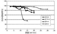
- FIG. 5 is a view showing a result of a liquid recovery experiment performed by attaching a tube having a relatively thin inner diameter of 3 mm or less to the wall surface.
- the horizontal axis represents the flow rate
- the vertical axis represents the EtOH recovery rate.
- Each pipe inner diameter ( ⁇ 1 mm, ⁇ 1.5 mm, ⁇ 2 mm, ⁇ 3 mm) showed a high recovery rate up to a certain threshold flow rate. When a certain threshold flow rate is exceeded, the recovery rate decreases as the flow rate increases.
- the liquid can be collected without scattering up to a flow rate of 10 ml / min (the linear velocity is sufficiently slow).
- the recovery rate decreases.
- the introduction flow path into which the mobile phase is introduced is branched into a plurality of discharge flow paths, and the flow rate per discharge flow path is reduced (the linear velocity is reduced) to cope with a large flow rate.
- Piping with a narrow inner diameter has advantages on the low flow side. For example, even at a low flow rate of 0.1 ml / min, the gas-liquid mixed fluid passes through the pipe while wetting the entire inner surface of the pipe.
- FIG. 6 is a diagram for explaining the flow of the gas-liquid mixed fluid in the pipe having a small inner diameter and the thick pipe.
- the liquid 303 flows so as to wet all the inner walls of the pipe by the surface tension of the liquid, and the gas 302 flows as bubbles.
- the tube 311 shown in FIGS. 6B and 6C is a tube having a relatively large inner diameter.
- the flow rate is large as shown in (b)
- the low-viscosity gas 312 flows through the center of the tube 311 and the liquid 313 flows so as to wet all the inner walls of the tube 311.
- the flow rate is small as shown in (c)
- the liquid 313 turns into droplets, and only a part of the inner wall of the tube 311 flows.
- the dynamic range of a tube having an inner diameter of 1.5 mm is 0.1 to 10 ml / min
- the dynamic range is 1.5 to 150 ml / min by using, for example, 15 tubes.
- the gas-liquid separator is realized.
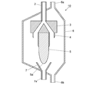
- FIG. 7 is a schematic cross-sectional view for explaining another embodiment of the gas-liquid separator.
- the gas-liquid separator 10 is installed, for example, upstream of the fraction collector.
- the gas-liquid separator 10 includes a chamber 6 that houses a gas-liquid separator having the inlet pipe 2, the flow path branching member 3, the plurality of discharge flow paths 4, and the attracting column 5 shown in FIG. 1.
- a driving force for sending liquid to the fraction collector is obtained by pressurizing the inside of the chamber 6 to about several atmospheric pressures, for example.
- the liquid dropped from the tip 5a of the liquid attracting column 5 of the gas-liquid separation device is collected by the receiving port 7 and fed from the liquid outlet 8 to the fraction collector.
- the vaporized CO 2 is filled in the chamber 6 and discharged from the CO 2 discharge port 6a.
- the chamber 6 is also provided with a waste liquid port 6b for cleaning.
- the gas-liquid separator 10 is disposed in a flow path between the pressure control valve 110 and the fraction collector 111 in, for example, the SFC shown in FIG.
- the feature of the gas-liquid separator 10 is that, unlike the prior art, the sample fluid does not pass through the inner wall of the chamber 6 that performs gas-liquid separation. Therefore, the size of the chamber 6 itself does not become a dead volume. That is, even if the chamber 6 is enlarged so as not to inhibit the flow of a large amount of vaporized CO 2, the liquid containing the sample passes only through the outer wall of the attracting column 5. In this case, the dead volume is not the volume of any structure but the volume of the liquid that travels through the attracting column 5. Therefore, the dead volume becomes extremely small, and the above-mentioned problem of cross contamination is avoided. Even if the sample is scattered on the gas CO 2 and adheres to the inner wall of the chamber 6, the adhering sample is only discharged from the waste liquid port 6b at the time of cleaning. It will not be.
- FIG. 8 is a schematic perspective view for explaining an example of a fraction collector including the gas-liquid separator according to the embodiment.
- the fraction collector 401 includes a gas-liquid separator 402, an XY stage 403, and a collection bottle holder 404.
- the gas-liquid separator 402 includes an inlet pipe 402a (introduction flow path), a plurality of discharge flow paths 402b, a suction block and a suction liquid column 402c (liquid collection member), and a cover 402d.
- a mobile phase is introduced into the inlet tube 402a.
- the plurality of discharge flow paths 402b are connected to the inlet pipe 402a.
- the discharge port 4a of the discharge flow path 402b is disposed in contact with the outer wall surface of the attracting block and the attracting column 402c.
- the cover 402d is disposed around the discharge flow path 402b, the attracting block and the attracting column 402c.
- the XY stage 403 moves the discharge head 403a in the XY direction.
- a gas-liquid separator 402 and a transfer pipe 405 are connected to the discharge head 403a.
- a plurality of collection bottles 406 are arranged in the collection bottle holding unit 404.
- the fraction collector 401 is used as the fraction collector 111 in the SFC shown in FIG.
- the mobile phase sent from the transfer pipe 405 to the gas-liquid separator 402 via the discharge head 403 a is gas-liquid separated by the gas-liquid separator 402.
- the separated liquid is dropped into the collection bottle 406 from the attracting block and the attracting column 402 c of the gas-liquid separator 402.
- the gas-liquid separator of the embodiment can be realized with a small size on the order of several centimeters, for example. Therefore, the gas-liquid separator 402 can be installed on the ejection head 403a of the fraction collector 401.
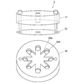
- FIG. 9 is a schematic exploded perspective view for explaining an example of the structure of the flow path branching member of the gas-liquid separator.
- the flow path branch member 3 includes, for example, a fluid introduction member 31, a seal member 32, and a branch member 33.
- the fluid introduction member 31 has a through hole having a diameter of about 1 mm at the center.
- the seal member 32 is provided with a through hole having a diameter of about 1 mm at the center like the fluid introduction member 31.
- the thickness of the seal member 32 is, for example, about 0.2 mm.
- the branch member 33 includes one hole having a diameter of about 1 mm provided at the center of the top surface and a plurality of holes provided on the bottom surface. The hole on the top and the hole on the bottom are in communication.
- the fluid introduction member 31, the seal member 32, and the branch member 33 are fastened with screws.
- the material of the fluid introduction member 31 and the branch member 33 is preferably SUS316, PEEK, or the like from the viewpoint of chemical resistance and sealability.
- the material of the seal member 32 is preferably softer than the material of the fluid introduction member 31 or the branch member 33, for example, ultra high molecular weight polyethylene or Kalrez (registered trademark).
- FIG. 10 is a schematic exploded perspective view for explaining another example of the structure of the flow path branching member of the gas-liquid separator.
- the flow path branch member 3 shown in FIG. 10 includes a branch member 34 instead of the branch member 33 of the flow path branch member 3 shown in FIG.
- the branch member 34 is not formed with a hole obliquely like the branch member 33, but a branch flow formed by a groove 34 a formed in a planar direction and a through hole provided at an end of the groove. It has a road.
- the branch member 34 has a smaller dead volume than the branch member 33.
- the branching member 34 can connect the piping of the discharge channel vertically.
- the branch member 34 can shorten the length of the piping of the discharge flow path to be connected, and can further reduce the dead volume.
- the groove 34a of the branching member 34 is formed with a uniform depth and the bottom surface of the groove 34a is horizontal, especially when the flow rate is very small, the expansion of chromatographic peaks due to retention and cross contamination. Nation is a concern.
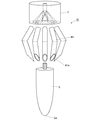
- FIG. 11 is a schematic exploded perspective view for explaining the structure of another embodiment of the gas-liquid separator.
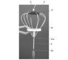
- the gas-liquid separator 11 includes an introduction flow path (not shown), a flow path branching member 3, a plurality of discharge flow paths 41, and an attracting column 5.
- the structure of the introduction channel, the channel branching member 3 and the attracting column 5 is the same as that of the gas-liquid separator 11 shown in FIG.
- the flow-path branch member 3 is integrally illustrated, the specific structure is the structure shown by FIG. 9 or FIG. 10, for example.
- pipes of a plurality of discharge flow paths 41 are connected to the flow path branching member 3.
- the discharge port 41 a of the discharge channel 41 is in contact with the outer wall of the attracting column 5.
- the optimum number of discharge channels 41 is determined depending on the inner diameter of the discharge channel 41. For example, 15 discharge channels 41 having an inner diameter of 1.5 mm are connected based on the experimental result of FIG.
- the flow path branching member 3 and the plurality of discharge flow paths 41 are connected by, for example, a ferrule and a mail nut used for general pipe fastening.
- the length from the tip of the discharge port 41a of the discharge channel 41 to the tip 5a of the attracting column 5 is 50 mm or more.
- the gap between the adjacent discharge ports 41a is secured at an interval of about 2 mm or more.
- FIG. 12 is a schematic exploded perspective view for explaining the structure of still another embodiment of the gas-liquid separator.
- the gas-liquid separator 12 includes an introduction channel (not shown), a channel branching member 3 and a liquid collecting member 51.
- the structure of the introduction channel and the channel branching member 3 is the same as that of the gas-liquid separator 11 shown in FIG.
- the liquid collecting member 51 is formed of, for example, a conical block.
- a discharge channel 51 a made of a through hole is formed inside the liquid collecting member 51.
- the discharge port 51 b of the discharge channel 51 a is disposed on the side wall surface (outer wall surface) of the liquid collection member 51.
- a groove 51c is formed at a position between the discharge port 51b and the tip 51d. The liquid discharged from the discharge port 51b of the discharge channel 51a adheres to the side wall surface of the liquid collecting member 51, moves to the tip portion 51d side, and drops from the tip portion 51d.
- the groove 51c is not necessarily formed.
- the gas-liquid separator 12 provided with the liquid collecting member 51 can greatly reduce the number of parts compared to the gas-liquid separator 11 shown in FIG. Further, in the gas-liquid separator 12, it is not necessary to consider the gap between the adjacent discharge ports. Therefore, the interval between the adjacent discharge ports 51b can be reduced, and the outer diameter of the liquid collection member 51, and thus the gas-liquid separator 12 can be manufactured in a compact manner.
- the groove 51c prevents stray flow of the liquid.
- the arrangement of the grooves 51c is particularly beneficial when the liquid flow rate is small.
- FIG. 13 is an image showing a gas-liquid separator actually manufactured based on the mechanism shown in FIG.
- FIG. 14 is a diagram showing the results of evaluating the liquid recovery rate after gas-liquid separation using the gas-liquid separator of FIG.
- the vertical axis indicates the liquid recovery rate
- the horizontal axis indicates the flow rate of the mobile phase in the introduction channel.
- the inner diameters of the pipes of the introduction channel and the branch channel are 1.5 mm in diameter.
- the outlet of each pipe of the branch channel is cut at 10 °.
- the liquid recovery rate at a flow rate of 10 to 150 ml / min when the number of branches was 4, 6, or 8 was evaluated.
- the number of branches of 6 or more separated gas and liquid even at a large flow rate of 150 ml / min, and a liquid recovery rate of 95% or more was obtained. Further, it can be seen that the liquid recovery rate is reduced at a flow rate of 40 ml / min or less. This is due to the inner surface roughness of the piping used and is not an essential characteristic of the gas-liquid separator.
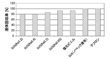
- FIG. 15 is a diagram showing a result of evaluating a difference in liquid recovery rate caused by the material of the pipe.
- the vertical axis indicates the recovery rate
- the horizontal axis indicates the material.
- the piping of each material was evaluated under the conditions of one pipe and a flow rate of 2.5 ml / min (equivalent to 20 ml / min for eight pipes).
- SUS (Ra3.2) shown on the leftmost side in FIG. 15 is the pipe used in the experiment of FIG. 14 and shows a low recovery rate of 80%.
- Teflon (registered trademark) tube shown on the rightmost side a recovery rate of 100% was obtained.
- Teflon registered trademark
- SUS has good water repellency and poor wettability.
- SUS has good wettability.
- SUS has a rough surface roughness of about Ra3.2.
- the extraction tube of Teflon (registered trademark) is about Ra 0.02.
- a high recovery rate was shown in an experimental result in which a coating agent Novec manufactured by 3M, which has good wettability, was applied to the inner surface of the SUS tube, and an experimental result using a vinyl chloride tube having good wettability. From this, it is considered that the good wettability of SUS itself is not a problem and is not the cause of the decrease in the recovery rate at a low flow rate. In addition, as a result of polishing the inner surface of the same SUS tube and increasing the smoothness to Ra of 0.4, 0.1, and 0.05, the liquid recovery rate was significantly improved. When the fluid is low speed, it is considered that the droplets are scattered due to the rough structure of the inner surface of the flow path and are scattered together with the CO 2 and disappeared.
- the cause of the decrease in the liquid recovery rate in the low flow rate region in FIG. 14 is the inner surface smoothness of the tube. Moreover, it is considered that a high liquid recovery rate can be obtained even in a low flow rate region by making the inner surface of the flow channel after branching smoothness of about Ra 0.05 or less.
- the experimental results in FIG. 14 are the results obtained by keeping the temperature of the mobile phase immediately before the gas-liquid separator at 10 ° C.
- the mobile phase In the supercritical fluid device, the mobile phase is usually heated to about 40 ° C. or higher in order to bring the fluid passing through the column or extraction vessel into a supercritical state.
- the temperature of the mobile phase is high, the recovery rate decreases due to the disappearance of the modifier due to evaporation. Therefore, it is preferable to lower the mobile phase introduced into the gas-liquid separator.
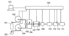
- FIG. 16 is a schematic configuration diagram for explaining another embodiment of the supercritical fluid device.
- a cooler 112 a temperature detector 113, a system controller 120 (control unit), and a monitor 121 are added as compared with the configuration shown in FIG.
- the temperature detector 113 detects the temperature of the cooler 112.
- system controller 120 is not essential for the operation of the SFC, it is usually attached to perform various automatic operations. System preparation performed by the system controller 120 will be described with reference to the flowchart of FIG. The preparation of the system here refers to the operation until the autosampler 106 is ready to inject a sample to be dispensed.
- FIG. 17 is a flowchart for explaining the system preparation operation of the supercritical fluid device.
- the system controller 120 first cools the CO 2 pump 103, heats the column oven 107, and cools the cooler 112 (step S1).
- the system controller 120 determines whether or not the temperature of the CO 2 pump 103 has sufficiently decreased using a temperature detector (not shown) (step S2).
- the system controller 120 CO 2 after the temperature of the pump 103 is equal to or less than a specified value (e.g., 5 ° C.), CO 2 pump 103 and operates the modifier pump 104 starts CO 2 and liquid delivery modifier ( Step S3).
- a specified value e.g., 5 ° C.
- the system controller 120 monitors the temperature of the cooler 112 using the temperature detector 113, and determines whether or not the temperature detected by the temperature detector 113 falls below a specified value (for example, 5 ° C.) (step S4).
- a specified value for example, 5 ° C.
- step S5 the sample injection operation of the autosampler 106 is started (step S5).
- the system controller 120 may display that the preparatory operation is possible on the monitor 121 in addition to the start of the injection operation, or display indicators of the system controller 120, the cooler 112, and the fraction collector 111. May be lit, or a combination of these operations may be performed.
- a temperature detector for detecting the temperature of the gas-liquid separator in the fraction collector 111 may be provided. Further, a gas-liquid separator may be provided in a flow path between the cooler 112 and the fraction collector 111, and a temperature detector that detects the temperature of the gas-liquid separator may be provided. Moreover, the temperature detector which detects the temperature of the mobile phase just before introduce
- FIG. 18 is a diagram showing experimental results in which the effect of cooling the mobile phase was verified.
- the vertical axis indicates the liquid recovery rate
- the horizontal axis indicates the temperature of the mobile phase.
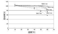
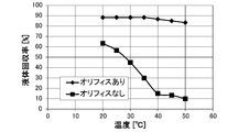
- FIG. 19 is a diagram showing the results of evaluating the temperature dependence of the liquid recovery rate when the orifice is installed just before the gas-liquid separator and when the orifice is not arranged.
- the vertical axis represents the liquid recovery rate
- the horizontal axis represents the temperature.
- the methanol flow rate was 1 ml / min
- the CO 2 flow rate was 4 ml / min
- the recovery rate of the flowing methanol was evaluated.
- the methanol recovery rate was 63% when the temperature was 20 ° C., but the methanol recovery rate gradually decreased as the set temperature increased, and 10% when the set temperature was 50 ° C. Only recovery was obtained.
- the recovery rate was constant 90% without depending on the temperature. From these results, it was confirmed that the recovery rate of the modifier was improved by using the cooling effect by instantaneously vaporizing CO 2 using the orifice without forcibly cooling the temperature of the fluid.
- the cooler using the orifice is disposed, for example, at the position of the cooler 112 in FIG.
- An orifice may be provided as a cooler at the connection between the pipe from the pressure control valve 110 and the pipe that continues to the fraction collector 111.
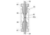
- FIG. 20 is a schematic cross-sectional view for explaining an example of a cooler having an orifice.
- the cooler 61 includes a joint 62 having an orifice 62a.
- the inlet pipe 63 and the outlet pipe 64 are connected via a joint 62.
- the inlet pipe 63 is connected to the joint 62 by a mail nut 65 and a ferrule 66.
- the outlet pipe 64 is connected to the joint 62 by a mail nut 67 and a ferrule 68.
- an orifice 62a is disposed between the end of the inlet pipe 63 and the end of the outlet pipe 64.
- the inner diameter of the orifice 62 a is smaller than the inner diameter of the inlet pipe 63 and the inner diameter of the outlet pipe 64.
- the internal diameter of the flow path of the mobile phase is reduced by the orifice 62a.
- the end of the inlet pipe 63 opposite to the joint 62 is connected to, for example, a back pressure regulator.
- the end of the outlet pipe 64 opposite to the joint 62 is connected to, for example, a gas-liquid separator.
- a mobile phase for example, supercritical CO 2 + modifier
- CO 2 is instantaneously vaporized at a short distance by the orifice 62a, and a mobile phase (gas-liquid mixed fluid) containing gaseous CO 2 is produced.
- a mobile phase gas-liquid mixed fluid
Landscapes
- Chemical & Material Sciences (AREA)
- Chemical Kinetics & Catalysis (AREA)
- General Health & Medical Sciences (AREA)
- Life Sciences & Earth Sciences (AREA)
- Analytical Chemistry (AREA)
- Biochemistry (AREA)
- Physics & Mathematics (AREA)
- General Physics & Mathematics (AREA)
- Immunology (AREA)
- Pathology (AREA)
- Health & Medical Sciences (AREA)
- Separating Particles In Gases By Inertia (AREA)
- Sampling And Sample Adjustment (AREA)
- Degasification And Air Bubble Elimination (AREA)
Abstract
Description
1つ目の分取方式は、複数の採集瓶に対して採集瓶ごとに気液分離器を設ける方式である。この方式は例えば特許文献1,3,7に開示されている。多数のフラクションはバルブによって流路を切り替えられて気液分離器を介して採集瓶に導かれる。1つの気液分離器には1つのフラクションしか通過しない。したがって、この方式は、デッドボリュームの大きさや、クロスコンタミネーション(例えばピーク個々がブロードになったりして互いに交じり合うこと)は問題とはならない利点がある。しかし、例えば市販の切り替えバルブは6方が最大であり、それ以上の個数のフラクション(分取対象クロマトピーク)を分取するためには複数段数にバルブを接続する必要があり、系が大規模複雑化するという問題が生じる。
図1は、気液分離器の一実施形態を説明するための概略的な斜視図である。図2は、超臨界流体装置の一実施形態を説明するための概略的な構成図である。まず、図2を参照して、超臨界流体装置の構成について説明する。
図3に示されたものが分取対象であるクロマトピーク群である。これらのピークの一つ一つはフラクションと呼ばれる。多数のフラクション(ピーク)が例えば秒単位で近接した状態で分離している。SFCでは、例えばこれらのフラクションすべてを取得する必要がある。
気液分離器1は、例えば移動相(CO2+モディファイア)を気体と液体に分離するものである。気液分離器1は、入口管2(導入流路)、流路分岐部材3、複数の吐出流路4及び誘液柱5(液体捕集部材)を備えている。入口管2には、例えば気体状態のCO2とモディファイア(液体)を含む移動相が導入される。複数の吐出流路4は流路分岐部材3を介して入口管2に接続されている。
配管201から気液混合流体が吐出する際、液体はコアンダ効果と呼ばれる現象により配管201に接した壁202の壁面に絡めとられ、壁面を伝って流れる。他方、気体は壁面とは無関係に自由空間に放出される。これにより、気体と液体の分離が実行される。
(1)コアンダ効果に基づき、配管出口を壁面に沿わせると液体のみが壁面を流れ、気液分離される。
(2)しかし流体線速度が大きいと、液体は気体に乗じてスプレーされ、飛散消失してしまう。
(3)流体線速度を抑制するためには流れ断面積を増大させることが有効である。
(4)しかし流れ断面積を増大させるために管内径を拡大すると旋回流によりクロスコンタミネーションの問題が生じる。
(5)旋回流を発生させないで流れ断面積を拡大する目的で、比較的細い内径を持つ複数の配管に分岐する。
(6)分岐された複数の配管の吐出口は柱の外壁に沿わせることで実質的な流路デッドボリュームを小さくする。
図6(a)に示した内径が比較的細い管301は、液体の表面張力により配管内壁全てを濡らすように液体303が流れ、気体302は気泡となって流れる。
図6(b),(c)に示した管311は内径が比較的太い管である。(b)に示すように流量が大きい場合には、粘度の低い気体312は管311の中心部を流れ、液体313は管311の内壁全てを濡らすように流れる。しかし、(c)に示すように流量が小さい場合には、液体313は液滴化し、管311の内壁の一部しか流れない。
気液分離器10は例えばフラクションコレクタの上流に設置されるものである。気液分離器10は、図1に示された入口管2、流路分岐部材3、複数の吐出流路4及び誘液柱5を有する気液分離器を収納するチャンバ6を備えている。気液分離器10では、チャンバ6内が例えば数気圧程度に加圧されることによってフラクションコレクタに液体を送液する駆動力が得られる。
フラクションコレクタ401は、気液分離器402と、X-Yステージ403と、捕集瓶保持部404を備えている。
流路分岐部材3は、例えば、流体導入部材31とシール部材32と分岐部材33を備えている。
図10に示された流路分岐部材3は、図9に示された流路分岐部材3の分岐部材33に替えて分岐部材34を備えている。
気液分離器11は、導入流路(図示は省略)、流路分岐部材3、複数の吐出流路41及び誘液柱5を備えている。導入流路、流路分岐部材3及び誘液柱5の構造は、図1に示された気液分離器11のものと同じである。なお、図11において流路分岐部材3は一体的に図示されているが、例えば、具体的な構造は図9又は図10に示された構造である。
気液分離器12は、導入流路(図示は省略)、流路分岐部材3及び液体捕集部材51を備えている。導入流路及び流路分岐部材3の構造は、図10に示された気液分離器11のものと同じである。
しかし、移動相の温度が高いと、モディファイアの蒸発による消失により、回収率が低下する。そこで、気液分離器に導入される移動相を低温にすることが好ましい。
この実施形態の超臨界流体装置は、図2に示された構成と比較して、冷却器112と温度検出器113とシステムコントローラ120(制御部)とモニタ121が追加されたものである。温度検出器113は冷却器112の温度を検出する。
冷却器61はオリフィス62aを有する継手62を備えている。入口管63と出口管64は継手62を介して接続されている。入口管63はメイルナット65及びフェルール66によって継手62に接続されている。出口管64はメイルナット67及びフェルール68によって継手62に接続されている。
2,402a 入口管(導入流路)
4,41,51a,402b 吐出流路
4a,41a,51b 吐出口
5,402c 誘液柱(液体捕集部材)
51 液体捕集部材
61,112 冷却器
62a オリフィス
103,104 ポンプ
106 オートサンプラ(試料注入器)
108 カラム
109 検出器
110 圧力制御バルブ(背圧調整器)
112 冷却器
113 温度検出器
120 制御部
Claims (10)
- 気体と液体とを含む移動相を気体と液体に分離する気液分離器であって、
移動相が導入される導入流路と、
前記導入流路に接続された複数の吐出流路と、を備え、
前記吐出流路の吐出口から気体及び液体が吐出される気液分離器。 - 前記吐出流路の吐出口から吐出された液体が付着して移動する外壁面を有する液体捕集部材をさらに備えている請求項1に記載の気液分離器。
- 前記液体捕集部材は円柱形状又は円錐形状である請求項2に記載の気液分離器。
- 前記液体捕集部材の内部に前記吐出流路の少なくとも一部分が形成されており、
前記液体捕集部材の前記外壁面に前記吐出流路の前記吐出口が形成されている請求項2又は3に記載の気液分離器。 - 前記吐出流路の内径は2mm以下である請求項1から4のいずれか一項に記載の気液分離器。
- ポンプと、背圧調整器と、請求項1から5のいずれか一項に記載の気液分離器と、を備え、
前記ポンプによって液体と超臨界流体又は液化気体を含む移動相が送液され、前記背圧調整器を通過した移動相が前記気液分離器に導入される超臨界流体装置。 - 前記背圧調整器と前記気液分離器の間に冷却器が接続されている請求項6に記載の超臨界流体装置。
- 前記冷却器はオリフィスを有する請求項7記載の超臨界流体装置。
- 前記ポンプと前記背圧調整器の間に接続された試料注入器と、
前記試料注入器と前記背圧調整器の間に接続されたカラムと、
前記カラムと前記背圧調整器の間に接続された検出器と、をさらに備えた請求項7又は8に記載の超臨界流体装置。 - 前記気液分離器に導入される直前の移動相の温度、前記冷却器の温度又は前記気液分離器の温度を検出するための温度検出器と、
前記温度検出器が検出した温度をモニタリングした結果が規定値以下になったことを判断して前記試料注入器を動作させる制御部と、をさらに備えている請求項9に記載の超臨界流体装置。
Priority Applications (5)
| Application Number | Priority Date | Filing Date | Title |
|---|---|---|---|
| JP2016548473A JP6269848B2 (ja) | 2014-09-17 | 2014-09-17 | 気液分離器及び超臨界流体装置 |
| CN201480081676.6A CN106794395B (zh) | 2014-09-17 | 2014-09-17 | 气液分离器和超临界流体装置 |
| PCT/JP2014/074539 WO2016042618A1 (ja) | 2014-09-17 | 2014-09-17 | 気液分離器及び超臨界流体装置 |
| US15/510,740 US10585076B2 (en) | 2014-09-17 | 2014-09-17 | Gas-liquid separator and super-critical fluid device |
| US16/665,209 US11226317B2 (en) | 2014-09-17 | 2019-10-28 | Gas-liquid separator and super-critical fluid device |
Applications Claiming Priority (1)
| Application Number | Priority Date | Filing Date | Title |
|---|---|---|---|
| PCT/JP2014/074539 WO2016042618A1 (ja) | 2014-09-17 | 2014-09-17 | 気液分離器及び超臨界流体装置 |
Related Child Applications (2)
| Application Number | Title | Priority Date | Filing Date |
|---|---|---|---|
| US15/510,740 A-371-Of-International US10585076B2 (en) | 2014-09-17 | 2014-09-17 | Gas-liquid separator and super-critical fluid device |
| US16/665,209 Continuation US11226317B2 (en) | 2014-09-17 | 2019-10-28 | Gas-liquid separator and super-critical fluid device |
Publications (1)
| Publication Number | Publication Date |
|---|---|
| WO2016042618A1 true WO2016042618A1 (ja) | 2016-03-24 |
Family
ID=55532684
Family Applications (1)
| Application Number | Title | Priority Date | Filing Date |
|---|---|---|---|
| PCT/JP2014/074539 Ceased WO2016042618A1 (ja) | 2014-09-17 | 2014-09-17 | 気液分離器及び超臨界流体装置 |
Country Status (4)
| Country | Link |
|---|---|
| US (2) | US10585076B2 (ja) |
| JP (1) | JP6269848B2 (ja) |
| CN (1) | CN106794395B (ja) |
| WO (1) | WO2016042618A1 (ja) |
Cited By (4)
| Publication number | Priority date | Publication date | Assignee | Title |
|---|---|---|---|---|
| CN109477818A (zh) * | 2016-08-03 | 2019-03-15 | 株式会社岛津制作所 | 流体处理装置以及处理液回收方法 |
| CN109564200A (zh) * | 2016-08-15 | 2019-04-02 | 安捷伦科技有限公司 | 用于收集色谱级分的气液分离器 |
| JP2020522720A (ja) * | 2017-05-16 | 2020-07-30 | アレクサンダー ボジッチAlexander Bozic | クロマトグラフィ設備用の気液分離器 |
| US20210116425A1 (en) * | 2018-04-13 | 2021-04-22 | Shimadzu Corporation | Extract recovery method and analysis method |
Families Citing this family (5)
| Publication number | Priority date | Publication date | Assignee | Title |
|---|---|---|---|---|
| US10585077B2 (en) * | 2015-04-10 | 2020-03-10 | Waters Technologies Corporation | Cooling liquid eluent of a carbon dioxide chromatography system after gas-liquid separation |
| US10994223B2 (en) * | 2017-05-30 | 2021-05-04 | Applied Separations, Inc. | Single phase high pressure liquefied gas chromatography system and method |
| EP3466512B1 (de) * | 2017-10-09 | 2020-04-29 | SEPIAtec GmbH | Sammlermodul für ein sfc-system |
| US20190227039A1 (en) * | 2018-01-22 | 2019-07-25 | Waters Technologies Corporation | Systems and methods for compressible fluid chromatography |
| EP3886116B1 (en) * | 2018-11-21 | 2024-10-09 | Korea Atomic Energy Research Institute | Nuclide separating device |
Citations (6)
| Publication number | Priority date | Publication date | Assignee | Title |
|---|---|---|---|---|
| JPS63221812A (ja) * | 1987-03-09 | 1988-09-14 | Matsushita Refrig Co | 分流器 |
| JPH0566220A (ja) * | 1991-09-09 | 1993-03-19 | Jeol Ltd | 超臨界流体クロマトグラフイと検出器とのインターフエース機構 |
| JP2000320933A (ja) * | 1999-05-11 | 2000-11-24 | Mitsubishi Electric Corp | 気液分離器およびその製造方法 |
| JP2005195398A (ja) * | 2004-01-05 | 2005-07-21 | Daicel Chem Ind Ltd | 超臨界流体クロマトグラフィーによる物質の分離方法及びこれに用いられる気液分離装置 |
| JP2007120972A (ja) * | 2005-10-25 | 2007-05-17 | Jasco Corp | 超臨界システム |
| WO2014083639A1 (ja) * | 2012-11-28 | 2014-06-05 | 株式会社島津製作所 | 超臨界流体処理装置 |
Family Cites Families (9)
| Publication number | Priority date | Publication date | Assignee | Title |
|---|---|---|---|---|
| US6685828B2 (en) * | 1999-09-16 | 2004-02-03 | Berger Instruments, Inc. | Automated sample collection in supercritical fluid chromatography |
| US6558540B2 (en) * | 2000-06-26 | 2003-05-06 | Berger Instruments, Inc. | Exhaust gas collection system for supercritical fluid chromatography |
| JP4675406B2 (ja) * | 2008-09-29 | 2011-04-20 | 日本分光株式会社 | 超臨界流体システムにおける試料回収容器と、試料回収装置および試料回収方法 |
| CN102091441A (zh) | 2010-12-31 | 2011-06-15 | 天津海纳科林机电设备科技发展有限公司 | 壁流式真空脱气机及循环液体自动脱气方法 |
| US10279294B2 (en) * | 2011-06-01 | 2019-05-07 | Agilent Technologies, Inc. | Self cleaning gas-liquid separator for serial or parallel collection of liquid fractions |
| EP2720769B1 (en) * | 2011-06-17 | 2020-07-29 | Waters Technologies Corporation | Methods and devices for open-bed atmospheric collection in supercritical fluid chromatography |
| JP6008482B2 (ja) * | 2011-09-15 | 2016-10-19 | 株式会社バンテック | 気体発生装置 |
| KR101985024B1 (ko) * | 2012-12-26 | 2019-05-31 | 현대모비스 주식회사 | 연료전지용 기액분리장치 |
| EP2772290A1 (en) * | 2013-02-28 | 2014-09-03 | Sulzer Chemtech AG | A devolatilisation apparatus and a process for use thereof |
-
2014
- 2014-09-17 CN CN201480081676.6A patent/CN106794395B/zh active Active
- 2014-09-17 WO PCT/JP2014/074539 patent/WO2016042618A1/ja not_active Ceased
- 2014-09-17 US US15/510,740 patent/US10585076B2/en active Active
- 2014-09-17 JP JP2016548473A patent/JP6269848B2/ja active Active
-
2019
- 2019-10-28 US US16/665,209 patent/US11226317B2/en active Active
Patent Citations (6)
| Publication number | Priority date | Publication date | Assignee | Title |
|---|---|---|---|---|
| JPS63221812A (ja) * | 1987-03-09 | 1988-09-14 | Matsushita Refrig Co | 分流器 |
| JPH0566220A (ja) * | 1991-09-09 | 1993-03-19 | Jeol Ltd | 超臨界流体クロマトグラフイと検出器とのインターフエース機構 |
| JP2000320933A (ja) * | 1999-05-11 | 2000-11-24 | Mitsubishi Electric Corp | 気液分離器およびその製造方法 |
| JP2005195398A (ja) * | 2004-01-05 | 2005-07-21 | Daicel Chem Ind Ltd | 超臨界流体クロマトグラフィーによる物質の分離方法及びこれに用いられる気液分離装置 |
| JP2007120972A (ja) * | 2005-10-25 | 2007-05-17 | Jasco Corp | 超臨界システム |
| WO2014083639A1 (ja) * | 2012-11-28 | 2014-06-05 | 株式会社島津製作所 | 超臨界流体処理装置 |
Cited By (8)
| Publication number | Priority date | Publication date | Assignee | Title |
|---|---|---|---|---|
| CN109477818A (zh) * | 2016-08-03 | 2019-03-15 | 株式会社岛津制作所 | 流体处理装置以及处理液回收方法 |
| CN109564200A (zh) * | 2016-08-15 | 2019-04-02 | 安捷伦科技有限公司 | 用于收集色谱级分的气液分离器 |
| CN109564200B (zh) * | 2016-08-15 | 2022-07-08 | 安捷伦科技有限公司 | 用于收集色谱级分的气液分离器 |
| US11491419B2 (en) | 2016-08-15 | 2022-11-08 | Agilent Technologies, Inc. | Gas-liquid separator for collecting chromatographic fractions |
| JP2020522720A (ja) * | 2017-05-16 | 2020-07-30 | アレクサンダー ボジッチAlexander Bozic | クロマトグラフィ設備用の気液分離器 |
| JP7191940B2 (ja) | 2017-05-16 | 2022-12-19 | ボジッチ アレクサンダー | クロマトグラフィ設備用の気液分離器 |
| US20210116425A1 (en) * | 2018-04-13 | 2021-04-22 | Shimadzu Corporation | Extract recovery method and analysis method |
| US12092618B2 (en) * | 2018-04-13 | 2024-09-17 | Shimadzu Corporation | Extract recovery method and analysis method using polymer beads in a trap when using supercritical extraction |
Also Published As
| Publication number | Publication date |
|---|---|
| CN106794395A (zh) | 2017-05-31 |
| US20170276654A1 (en) | 2017-09-28 |
| CN106794395B (zh) | 2019-04-23 |
| JP6269848B2 (ja) | 2018-01-31 |
| US10585076B2 (en) | 2020-03-10 |
| JPWO2016042618A1 (ja) | 2017-05-25 |
| US20200057034A1 (en) | 2020-02-20 |
| US11226317B2 (en) | 2022-01-18 |
Similar Documents
| Publication | Publication Date | Title |
|---|---|---|
| JP6269848B2 (ja) | 気液分離器及び超臨界流体装置 | |
| EP2168647B1 (en) | Sample collection container, sample collection apparatus, and sample collection method in supercritical fluid system | |
| JP5683107B2 (ja) | プロセスフローストリーム採取システム | |
| US8968561B2 (en) | Preparative separation/purification system | |
| JP6615764B2 (ja) | 液体をイオン源に送達するためのシステムおよび方法 | |
| WO2014083639A1 (ja) | 超臨界流体処理装置 | |
| EP3330705B1 (en) | Microfluidic check valve and related devices and systems | |
| CN109564200B (zh) | 用于收集色谱级分的气液分离器 | |
| JP2017219321A (ja) | 気液分離器及び超臨界流体装置 | |
| JP6264500B2 (ja) | サンプル捕集装置及び超臨界流体装置並びにサンプル捕集方法 | |
| JP4807355B2 (ja) | 気液二相流クロマトグラフ分析装置及び該装置を用いる分析方法 | |
| US20150298025A1 (en) | Focused sample delivery and eluent selection for chromatography | |
| US9921191B2 (en) | Gas chromatographic (GC) unit, scalable GC systems using same, and related methods | |
| CN100403025C (zh) | 用于液相色谱的分离装置 | |
| JP7515949B1 (ja) | 気液分離器及びこれを用いた試料の回収方法 | |
| EP3532836B1 (en) | Gas liquid separator for chromatography applications | |
| WO2016046990A1 (ja) | サンプル捕集装置及び超臨界流体装置並びにサンプル捕集方法 | |
| EP4273556B1 (en) | Autosampler seal pack for reducing a carryover percentage | |
| JP7191940B2 (ja) | クロマトグラフィ設備用の気液分離器 | |
| JPH0566220A (ja) | 超臨界流体クロマトグラフイと検出器とのインターフエース機構 | |
| JP3196131U (ja) | 超臨界流体装置 |
Legal Events
| Date | Code | Title | Description |
|---|---|---|---|
| 121 | Ep: the epo has been informed by wipo that ep was designated in this application |
Ref document number: 14902170 Country of ref document: EP Kind code of ref document: A1 |
|
| ENP | Entry into the national phase |
Ref document number: 2016548473 Country of ref document: JP Kind code of ref document: A |
|
| WWE | Wipo information: entry into national phase |
Ref document number: 15510740 Country of ref document: US |
|
| NENP | Non-entry into the national phase |
Ref country code: DE |
|
| 122 | Ep: pct application non-entry in european phase |
Ref document number: 14902170 Country of ref document: EP Kind code of ref document: A1 |