WO2016035262A1 - 圧電素子駆動式バルブ及び圧電素子駆動式バルブを備えた流量制御装置 - Google Patents
圧電素子駆動式バルブ及び圧電素子駆動式バルブを備えた流量制御装置 Download PDFInfo
- Publication number
- WO2016035262A1 WO2016035262A1 PCT/JP2015/004062 JP2015004062W WO2016035262A1 WO 2016035262 A1 WO2016035262 A1 WO 2016035262A1 JP 2015004062 W JP2015004062 W JP 2015004062W WO 2016035262 A1 WO2016035262 A1 WO 2016035262A1
- Authority
- WO
- WIPO (PCT)
- Prior art keywords
- piezoelectric element
- actuator
- valve
- piezoelectric
- spacer
- Prior art date
- Legal status (The legal status is an assumption and is not a legal conclusion. Google has not performed a legal analysis and makes no representation as to the accuracy of the status listed.)
- Ceased
Links
Images





Classifications
-
- F—MECHANICAL ENGINEERING; LIGHTING; HEATING; WEAPONS; BLASTING
- F16—ENGINEERING ELEMENTS AND UNITS; GENERAL MEASURES FOR PRODUCING AND MAINTAINING EFFECTIVE FUNCTIONING OF MACHINES OR INSTALLATIONS; THERMAL INSULATION IN GENERAL
- F16K—VALVES; TAPS; COCKS; ACTUATING-FLOATS; DEVICES FOR VENTING OR AERATING
- F16K31/00—Actuating devices; Operating means; Releasing devices
- F16K31/004—Actuating devices; Operating means; Releasing devices actuated by piezoelectric means
-
- F—MECHANICAL ENGINEERING; LIGHTING; HEATING; WEAPONS; BLASTING
- F16—ENGINEERING ELEMENTS AND UNITS; GENERAL MEASURES FOR PRODUCING AND MAINTAINING EFFECTIVE FUNCTIONING OF MACHINES OR INSTALLATIONS; THERMAL INSULATION IN GENERAL
- F16K—VALVES; TAPS; COCKS; ACTUATING-FLOATS; DEVICES FOR VENTING OR AERATING
- F16K31/00—Actuating devices; Operating means; Releasing devices
- F16K31/004—Actuating devices; Operating means; Releasing devices actuated by piezoelectric means
- F16K31/007—Piezoelectric stacks
-
- F—MECHANICAL ENGINEERING; LIGHTING; HEATING; WEAPONS; BLASTING
- F16—ENGINEERING ELEMENTS AND UNITS; GENERAL MEASURES FOR PRODUCING AND MAINTAINING EFFECTIVE FUNCTIONING OF MACHINES OR INSTALLATIONS; THERMAL INSULATION IN GENERAL
- F16K—VALVES; TAPS; COCKS; ACTUATING-FLOATS; DEVICES FOR VENTING OR AERATING
- F16K7/00—Diaphragm valves or cut-off apparatus, e.g. with a member deformed, but not moved bodily, to close the passage ; Pinch valves
- F16K7/12—Diaphragm valves or cut-off apparatus, e.g. with a member deformed, but not moved bodily, to close the passage ; Pinch valves with flat, dished, or bowl-shaped diaphragm
- F16K7/14—Diaphragm valves or cut-off apparatus, e.g. with a member deformed, but not moved bodily, to close the passage ; Pinch valves with flat, dished, or bowl-shaped diaphragm arranged to be deformed against a flat seat
-
- F—MECHANICAL ENGINEERING; LIGHTING; HEATING; WEAPONS; BLASTING
- F16—ENGINEERING ELEMENTS AND UNITS; GENERAL MEASURES FOR PRODUCING AND MAINTAINING EFFECTIVE FUNCTIONING OF MACHINES OR INSTALLATIONS; THERMAL INSULATION IN GENERAL
- F16K—VALVES; TAPS; COCKS; ACTUATING-FLOATS; DEVICES FOR VENTING OR AERATING
- F16K7/00—Diaphragm valves or cut-off apparatus, e.g. with a member deformed, but not moved bodily, to close the passage ; Pinch valves
- F16K7/12—Diaphragm valves or cut-off apparatus, e.g. with a member deformed, but not moved bodily, to close the passage ; Pinch valves with flat, dished, or bowl-shaped diaphragm
- F16K7/14—Diaphragm valves or cut-off apparatus, e.g. with a member deformed, but not moved bodily, to close the passage ; Pinch valves with flat, dished, or bowl-shaped diaphragm arranged to be deformed against a flat seat
- F16K7/16—Diaphragm valves or cut-off apparatus, e.g. with a member deformed, but not moved bodily, to close the passage ; Pinch valves with flat, dished, or bowl-shaped diaphragm arranged to be deformed against a flat seat the diaphragm being mechanically actuated, e.g. by screw-spindle or cam
-
- G—PHYSICS
- G05—CONTROLLING; REGULATING
- G05D—SYSTEMS FOR CONTROLLING OR REGULATING NON-ELECTRIC VARIABLES
- G05D7/00—Control of flow
- G05D7/06—Control of flow characterised by the use of electric means
- G05D7/0617—Control of flow characterised by the use of electric means specially adapted for fluid materials
- G05D7/0629—Control of flow characterised by the use of electric means specially adapted for fluid materials characterised by the type of regulator means
- G05D7/0635—Control of flow characterised by the use of electric means specially adapted for fluid materials characterised by the type of regulator means by action on throttling means
-
- H—ELECTRICITY
- H10—SEMICONDUCTOR DEVICES; ELECTRIC SOLID-STATE DEVICES NOT OTHERWISE PROVIDED FOR
- H10N—ELECTRIC SOLID-STATE DEVICES NOT OTHERWISE PROVIDED FOR
- H10N30/00—Piezoelectric or electrostrictive devices
- H10N30/20—Piezoelectric or electrostrictive devices with electrical input and mechanical output, e.g. functioning as actuators or vibrators
-
- H—ELECTRICITY
- H10—SEMICONDUCTOR DEVICES; ELECTRIC SOLID-STATE DEVICES NOT OTHERWISE PROVIDED FOR
- H10N—ELECTRIC SOLID-STATE DEVICES NOT OTHERWISE PROVIDED FOR
- H10N30/00—Piezoelectric or electrostrictive devices
- H10N30/50—Piezoelectric or electrostrictive devices having a stacked or multilayer structure
-
- H—ELECTRICITY
- H10—SEMICONDUCTOR DEVICES; ELECTRIC SOLID-STATE DEVICES NOT OTHERWISE PROVIDED FOR
- H10N—ELECTRIC SOLID-STATE DEVICES NOT OTHERWISE PROVIDED FOR
- H10N30/00—Piezoelectric or electrostrictive devices
- H10N30/80—Constructional details
- H10N30/88—Mounts; Supports; Enclosures; Casings
-
- H—ELECTRICITY
- H10—SEMICONDUCTOR DEVICES; ELECTRIC SOLID-STATE DEVICES NOT OTHERWISE PROVIDED FOR
- H10N—ELECTRIC SOLID-STATE DEVICES NOT OTHERWISE PROVIDED FOR
- H10N30/00—Piezoelectric or electrostrictive devices
- H10N30/80—Constructional details
- H10N30/88—Mounts; Supports; Enclosures; Casings
- H10N30/886—Additional mechanical prestressing means, e.g. springs
Definitions
- the present invention relates to a piezoelectric element driving valve and a piezoelectric element driving valve that are interposed in a fluid supply line of semiconductor manufacturing equipment, chemical industry equipment, pharmaceutical industry equipment, food industry equipment, etc.
- the present invention relates to a piezoelectric element driving valve that can increase the amount of displacement of a piezoelectric element and does not hinder wiring and the like, and a flow control device including the piezoelectric element driving valve. It is.
- Patent Document 1 in fluid supply lines such as semiconductor manufacturing equipment and chemical industry equipment, piezoelectric element-driven valves and flow control devices including piezoelectric element-driven valves have been widely used (for example, Patent Document 1, Patent Document). 2, Patent Document 3, Patent Document 4, Patent Document 5, Patent Document 6 and Patent Document 7).
- FIG. 9 shows an example of a flow rate control device provided with the conventional piezoelectric element drive type valve 30 and the piezoelectric element drive type valve 30.
- the flow rate control device includes a piezoelectric element driving valve 30 and an inlet side that is fastened and fixed to the upstream side of the main body 31 of the piezoelectric element driving valve 30 by a bolt (not shown) and communicates with the fluid passage 31a of the main body 31.
- a flow rate control gasket interposed between the main body 31 and the outlet side block 34.
- the outlet side block 34 is formed with an outlet side fluid passage 34a communicating with the fluid passage 31a of the main body 31.
- the pressure orifice is disposed in the die orifice 35 and the main body 31 of the piezoelectric element driven valve 30 and detects the pressure upstream of the gasket orifice 35.
- the piezoelectric element driven valve 30 includes a main body 31 provided with a fluid passage 31a and a valve seat 31b, a valve body 38 (metal diaphragm) that contacts and separates from the valve seat 31b, and an outer peripheral edge portion of the valve body 38.
- Presser adapter 39 that presses against the main body 31 in an airtight manner
- split base 40 with a half-split structure that presses the presser adapter 39 toward the main body 31
- base presser 41 that fixes the presser adapter 39 and the split base 40 toward the main body 31.
- an actuator box 42 supported by the base presser 41 so as to be movable up and down, a diaphragm presser 43 which is inserted into the lower end of the actuator box 42 and abuts against the valve body 38, and an intermediate between the split base 40 and the actuator box 42.
- an elastic body 44 that presses and biases the actuator box 42 downward, and is accommodated in the actuator box 42.
- the lower end side is screwed to the upper end portion of the piezoelectric actuator 46 supported by the split base 40 via the lower base 45 and the actuator box 42, and the upper end side of the piezoelectric actuator 46 is passed through the upper base 47 and the thrust bearing 48.
- the actuator box 42 When the piezoelectric actuator 46 is extended by applying a voltage, the actuator box 42 is supported by the base presser 41 and resists the elastic force of the elastic body 44. Along with this, the valve body 38 is separated from the valve seat 31b by its elastic force to open the fluid passage 31a, and when the voltage applied to the piezoelectric actuator 46 is released, the piezoelectric actuator 46 is released from the extended state. While returning to the original length dimension, the actuator box 42 is pushed by the elastic force of the elastic body 44. Lowered, the valve body 38 along with this is configured piezoelectric driven valve 30 of the normally closed type which closes the fluid passage 31a by checking is pressed downward into the valve seat 31b by the diaphragm presser 43.
- the piezoelectric actuator 46 using a piezoelectric element has a large thrust and excellent response and control characteristics, but has a problem that the displacement of the piezoelectric element is very small and the stroke cannot be increased.
- a piezoelectric element drive type valve has been developed in which the displacement amount of the piezoelectric element is expanded by a displacement expansion mechanism having a lever structure and transmitted to the valve rod (for example, Patent Document 2 and (See Patent Document 6).
- the piezoelectric element driven valve must incorporate a displacement magnifying mechanism having a complicated structure between the piezoelectric actuator and the valve stem, which causes another problem that it takes time to assemble.
- a piezoelectric element driving type valve having a structure in which two piezoelectric actuators are stacked one above the other may be used.
- the valve is not developed yet.
- a piezoelectric element drive type valve in which two piezoelectric actuators are simply stacked one above the other causes a problem in wiring and the like.
- a long piezoelectric actuator If a long piezoelectric actuator is manufactured, the stroke can be increased.
- a piezoelectric actuator of a type in which piezoelectric elements are stacked if the piezoelectric element is elongated, the entire piezoelectric element is warped. There is a problem that a long piezoelectric actuator with high accuracy cannot be produced. Further, when the piezoelectric element is elongated, there is a problem that the piezoelectric element becomes weak against an external force from the lateral direction (a direction perpendicular to the axis), and the piezoelectric element is easily damaged by an impact from the lateral direction.
- the present invention has been made in view of such problems, and its object is to increase the amount of displacement of the piezoelectric element without using a complicated mechanism, and to hinder wiring and the like.
- An object of the present invention is to provide a piezoelectric element drive type valve and a flow rate control device including the piezoelectric element drive type valve.
- a first aspect of a piezoelectric element driven valve includes a main body provided with a fluid passage and a valve seat, and a valve that opens and closes the fluid passage by being separated from the valve seat of the main body.
- a piezoelectric element drive type valve comprising a body and a piezoelectric actuator that opens and closes the valve body by utilizing the extension of the piezoelectric element
- at least two piezoelectric actuators are arranged in a straight line through a spacer that can draw out wiring. It is characterized by being arranged and stacked.
- a second aspect of the piezoelectric element driving valve according to the present invention further includes a bottomed cylindrical actuator box that accommodates and supports at least two piezoelectric actuators in a straight line in the first aspect,
- the actuator box is configured to detachably connect a first cylindrical portion that accommodates one piezoelectric actuator, a second cylindrical portion that accommodates the other piezoelectric actuator, and a first cylindrical portion and a second cylindrical portion. It is characterized by comprising a cylindrical connecting body that forms a space for accommodating a spacer between the actuator and the other piezoelectric actuator, and an opening through which wiring can be drawn is formed in the connecting body.
- the valve element is formed of a self-elastic return type metal diaphragm and the actuator box is movably supported on the main body side in the second aspect.
- a split base having an upper wall that passes through the peripheral wall of the actuator box and faces the upper surface of the bottom wall of the actuator box, and is interposed between the bottom wall of the actuator box and the upper wall of the split base.
- an elastic body that presses and urges the actuator box toward the valve body to cause the valve body to abut against the valve seat, and when the piezoelectric actuator is extended, the actuator box is moved against the elastic force of the elastic body to move the valve It is characterized by the body separating from the valve seat.
- a fourth aspect of the piezoelectric element drive type valve according to the present invention is the cylinder according to the first aspect, the second aspect, or the third aspect, wherein the spacer has an opening or a notch that can draw out the wiring on the peripheral wall. It is characterized by being formed into a shape.
- a fifth aspect of the piezoelectric element drive type valve according to the present invention is characterized in that, in the fourth aspect, a plurality of openings or notches are formed at a constant interval in the circumferential direction on the peripheral wall of the spacer. is there.
- the spacer is formed in a circular fence structure or a circular lattice structure from which the wiring can be drawn. It is characterized by being.
- the seventh aspect of the piezoelectric element driven valve according to the present invention is characterized in that, in the second aspect or the third aspect, the spacer and the actuator box are formed of a material having the same thermal expansion coefficient. is there.
- the spacer, the first cylindrical portion, the second cylindrical portion, and the coupling body of the actuator box are each formed of the same invar material. There is a feature.
- a first aspect of the flow rate control device is characterized by including the piezoelectric element drive type valve described in the first aspect.
- an orifice disposed in a fluid passage downstream of the valve body, and a fluid passage between the valve body and the orifice
- a control unit that controls one piezoelectric actuator and the other piezoelectric actuator based on a detection value of the pressure sensor.
- a third aspect of the flow control device is characterized in that, in the first aspect of the flow control device, the piezoelectric actuator is controlled by a thermal flow sensor disposed upstream of the valve element. .
- the piezoelectric element drive type valve according to the present invention has a configuration in which at least two piezoelectric actuators are arranged in a vertical line via a spacer capable of pulling out a wiring, so that a conventional piezoelectric element using only one piezoelectric actuator is used.
- the displacement amount of the piezoelectric element can be increased as compared with the drive type valve, and as a result, the stroke is increased and a fluid having a large flow rate can be controlled.
- the piezoelectric element driven valve of the present invention has a structure in which two piezoelectric actuators are arranged via a spacer, so that a complicated structure is formed between the piezoelectric actuator and the valve stem as in the conventional piezoelectric element driven valve. There is no need to incorporate a displacement magnifying mechanism, and assembly can be performed easily and easily.
- the piezoelectric element drive type valve of the present invention has a configuration in which the spacer can pull out the wiring, the wiring can be performed even if two piezoelectric actuators are provided.
- wiring can be drawn out in any direction of the spacer. Convenient.
- the spacer and the actuator box that accommodates the piezoelectric actuator are formed of the same material having a small coefficient of thermal expansion, so that the expansion and contraction amount of the spacer and the actuator box due to heat can be matched.
- there is no gap at the upper end of the upper piezoelectric actuator and the generated force can be reliably and satisfactorily transmitted to the actuator box when the piezoelectric element of the piezoelectric actuator is extended, so that highly accurate flow control can be performed.
- the flow control device of the present invention includes a piezoelectric element drive type valve in which at least two piezoelectric actuators are arranged in a straight line with a spacer interposed therebetween, so that a high flow rate fluid can be controlled with high accuracy. .
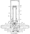
- FIG. 1 shows a flow rate control device provided with a piezoelectric element drive type valve 1 according to an embodiment of the present invention.
- the flow rate control device is upstream of a piezoelectric element drive type valve 1 and a main body 7 of the piezoelectric element drive type valve 1.
- the inlet side block 2 which is fastened and fixed to the side by a bolt (not shown) and forms the inlet side fluid passage 2a communicating with the fluid passage 7a of the main body 7, and is interposed between the main body 7 and the inlet side block 2
- a gasket type orifice 5 for controlling the flow rate interposed between the main body 7 and the outlet side block 4, and the main body 7 of the piezoelectric element driven valve 1, and upstream of the gasket type orifice 5.
- a pressure sensor 6 for detecting the pressure of the piezoelectric element and a control unit (not shown) for controlling the piezoelectric element driven valve 1.
- the piezoelectric element while calculating the flow rate through the orifice by the upstream pressure of the gasket type orifice 5
- the inlet side block 2, the outlet side block 4, the gasket type orifice 5, the pressure sensor 6 and the control unit are configured in the same manner as a conventionally known one, a detailed description thereof will be given here. Omitted.
- the flow control device provided with the piezoelectric element drive type valve 1 shown in FIG. 1 is used by arranging the device itself vertically.
- the piezoelectric element driven valve 1 includes a main body 7, a valve body 8, a presser adapter 9, a split base 10, a base presser 11, a bottomed cylindrical actuator box 12, and a diaphragm. Presser foot 13, elastic body 14, lower cradle 15, two upper and lower two piezoelectric actuators 16, spacer 17, upper cradle 18, thrust bearing 19, adjustment cap nut 20, lock nut
- the actuator box 12 is lifted against the elastic force of the elastic body 14 while being supported by the base presser 11.
- the main body 7 is formed in a block shape from a metal material such as a stainless steel material, and the fluid passage 7a and the upper portion that communicates with the fluid passage 7a and forms a part of the valve chamber are opened.
- a recess 7b and an annular valve seat 7c formed on the bottom surface of the valve chamber are provided.
- the valve body 8 is composed of a self-resilient return-type metal diaphragm formed in an inverted dish shape with a central portion slightly bulging upward by a metal material having excellent durability, corrosion resistance, and heat resistance, and a valve seat 7c. It is arranged in the concave portion 7b so as to be opposed, and its outer peripheral edge is held and fixed in an airtight manner to the main body 7 side by a presser adapter 9 or the like, and is seated against the valve seat 7c by pressing downward, and when the pressing force is lost. The elastic seat is separated from the valve seat 7c.
- the metal diaphragm may be made of stainless steel, Inconel, or other alloy steel.
- the metal diaphragm may be a single metal diaphragm or a metal diaphragm in which a plurality of diaphragms are laminated. Furthermore, the shape of the metal diaphragm may be a flat plate shape.
- the presser adapter 9 is formed in an annular shape from a metal material such as stainless steel, and is inserted into the recess 7b of the main body 7 to press the outer peripheral edge of the valve body 8 (metal diaphragm) in an airtight manner toward the main body 7 side. It is to be fixed.
- the split base 10 is composed of a pair of half split base pieces 10 ′ formed of a metal material such as stainless steel, and each split base piece 10 ′ is connected to the actuator box 12. Assemble to the lower end (base end) from both sides, and in this state, each split base piece 10 'and the lower end of the actuator box 12 are inserted into the recess 7b of the main body 7, and the base is inserted into the recess 7b. The lower end portion of the presser 11 is inserted, and the base presser 11 is fastened and fixed to the main body 7 with the bolt 22, so that the presser adapter 9 is pressed and held and fixed to the concave portion 7 b of the main body 7.
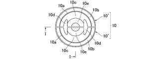
- the two split base pieces 10 ′ constituting the split base 10 include a short cylindrical portion 10 a, a flange portion 10 b that is connected to the lower end of the cylindrical portion 10 a and is inserted into the concave portion 7 b of the main body 7, and a cylindrical portion. 10a, an upper wall 10c continuously provided at the upper end, an insertion hole 10d formed in the upper wall 10c through which a part of the peripheral wall of the actuator box 12 is inserted, and a lower end of the actuator box 12 provided continuously with the upper wall 10c.
- a fitting portion 10e that is inserted through a guide hole 12d formed in the peripheral wall of the actuator box 12 and faces the upper surface of the bottom wall 12c of the actuator box 12 is provided.
- the actuator box 12 is pressed downward to urge the central portion of the valve body 8 through the diaphragm retainer 13.
- An elastic body 14 composed of a plurality of disc springs to be seated against 7c is interposed.
- the base presser 11 is formed in a cylindrical shape from a metal material such as stainless steel, and a flange portion 11a facing the inner peripheral edge of the recess 7b of the main body 7 is formed on the outer peripheral surface of the lower end portion. A plurality of O-rings 23 are fitted on the inner peripheral surface at regular intervals.
- the base presser 11 is fixed in an upright posture to the main body 7 side by a bolt 22 and supports the actuator box 12 so as to be movable up and down to the main body 7 side. This is for pressing and fixing the ten flanges 10b to the main body 7 side.
- the actuator box 12 is formed in a bottomed cylindrical shape from a material having a low thermal expansion coefficient (preferably 2 ⁇ 10 ⁇ 6 / K or less), and includes two piezoelectric actuators 16, an elastic body 14, with the lower cradle 15 and the spacer 17 accommodated and supported in a straight line, the lower end thereof is inserted and supported by the base presser 11 through the O-ring 23 so as to be movable up and down.
- a material having a low thermal expansion coefficient preferably 2 ⁇ 10 ⁇ 6 / K or less
- the actuator box 12 accommodates the bottom (one) piezoelectric actuator 16, the elastic body 14, and the bottom cylindrical first cylinder portion 12 ⁇ / b> A that accommodates the lower pedestal 15, and the upper (other) piezoelectric actuator 16.
- the second cylindrical portion 12B, the first cylindrical portion 12A, and the second cylindrical portion 12B are detachably connected, and a spacer 17 is provided between the lower (one) piezoelectric actuator 16 and the upper (other) piezoelectric actuator 16.
- a cylindrical connecting body 12 ⁇ / b> C that forms a storage space such as a storage space, and acts to push down the central portion of the valve body 8 downward.
- the first cylindrical portion 12A is formed into a bottomed cylindrical shape by an invar material such as invar, super invar, stainless invar, etc., and houses the lower piezoelectric actuator 16 and its lower end is a base presser. 11, a cylindrical large-diameter portion 12a that is slidably inserted in the vertical direction through an O-ring 23, and a lower end of the large-diameter portion 12a. It consists of a cylindrical small-diameter portion 12b to be housed. Further, a bottom wall 12c is integrally provided inside the small-diameter portion 12b.
- invar material such as invar, super invar, stainless invar, etc.
- the elastic body 14 and the lower receiving base 15 are accommodated in a space above the bottom wall 12c, and a diaphragm is disposed in a space below the bottom wall 12c.
- the presser 13 is inserted and fixed.
- a vertically long guide hole 12d into which the fitting portion 10e of the split base 10 is inserted is formed on the peripheral wall of the boundary portion between the large diameter portion 12a and the small diameter portion 12b so as to face each other.
- a male screw 12e is formed on the outer peripheral surface of the upper end portion of the large-diameter portion 12a to which the connecting body 12C is detachably screwed.
- the second cylindrical portion 12B is formed in a cylindrical shape from an invar material such as invar, super invar, or stainless invar, and houses the upper piezoelectric actuator 16 inward.
- a male screw 12f to which the connecting body 12C is detachably screwed is formed on the outer peripheral surface of the lower end portion of the second cylindrical portion 12B, and an adjustment purpose is provided on the outer peripheral surface of the upper end portion of the second cylindrical portion 12B.
- a male screw 12f is formed on which the cap nut 20 and the lock nut 21 are screwed so as to be movable in the vertical direction.
- the connecting body 12C is formed in a cylindrical shape by an invar material such as invar, super invar, stainless invar, etc., and connects the first cylindrical portion 12A and the second cylindrical portion 12B to the inner side.
- the spacer 17, the lead terminal 16 c, the connector (not shown), and the like are accommodated.
- On the inner peripheral surfaces of both ends of the connecting body 12C there are formed female screws 12g that are detachably screwed to the male screws 12e of the first cylindrical portion 12A and the male screws 12f of the second cylindrical portion 12B, respectively.
- An opening 12h through which wiring can be drawn is formed in the peripheral wall.
- a plurality of openings 12h may be formed at regular intervals along the circumferential direction on the peripheral wall of the connecting body 12C. good. In this case, the wiring can be drawn out in any direction of the connecting body 12C.
- each of the upper and lower two-stage piezoelectric actuators 16 includes a laminated piezoelectric element (not shown) housed in a metal casing 16a whose one end is closed, and the other end of the casing 16a. Is sealed with a stepped base 16b, and the lead terminal 16c protrudes from the base 16b. A hemispherical displacement provided at the tip of the casing 16a as the piezoelectric element expands and contracts.
- the portion 16 d is configured as a stacked piezoelectric actuator 16 that reciprocates along the axis of the piezoelectric actuator 16.
- the lower piezoelectric actuator 16 is housed in the first tube portion 12A of the actuator box 12 with its hemispherical displacement portion 16d facing downward, and its lower end (displacement portion 16d). Is supported by the fitting portion 10 e of the split base 10 via the lower receiving base 15, and the lead terminal 16 c is located in the spacer 17.
- the lower pedestal 15 is formed in a disk shape from a metal material such as stainless steel, and is fitted in a state where the hemispherical displacement portion 16d of the lower piezoelectric actuator 16 is positioned at the center of the upper surface. A conical receiving groove is formed.
- the upper piezoelectric actuator 16 is housed in the second cylindrical portion 12B of the actuator box 12 with its hemispherical displacement portion 16d facing upward, and its lower end (stepped)
- the base 16b is stacked on the lower piezoelectric actuator 16 via the spacer 17, and the upper end portion (displacement portion 16d) of the second cylinder portion 12B is screwed to the upper end portion of the second cylindrical portion 12B so as to be movable in the vertical direction.
- the adjustment cap nut 20 is supported via an upper cradle 18 and a thrust bearing 19 so that the position can be adjusted.
- the lead terminal 16 c of the upper piezoelectric actuator 16 is located in the spacer 17 like the lead terminal 16 c of the lower piezoelectric actuator 16.
- the upper pedestal 18 is formed in a disk shape from a metal material such as stainless steel, and is fitted with a hemispherical displacement portion 16d of the upper piezoelectric actuator 16 positioned at the center of the lower surface thereof. A conical receiving groove is formed.
- the upper and lower two-stage piezoelectric actuators 16 extend upward by applying a voltage and push the actuator box 12 upward against the elastic force of the elastic body 14.
- the spacer 17 is formed of a material having a low thermal expansion coefficient (preferably 2 ⁇ 10 ⁇ 6 / K or less) like the actuator box 12 in order to match the expansion and contraction amount of the spacer 17 and the actuator box 12 due to heat. Yes.
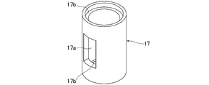
- the spacer 17 is formed in a cylindrical shape by an invar material such as invar, super invar, stainless invar, etc., and one rectangular opening 17a from which wiring can be drawn is formed on the peripheral wall.
- a stepped portion 17b that fits tightly to a stepped base 16b of the upper piezoelectric actuator 16 and a stepped base 16b of the lower piezoelectric actuator 16 is formed on the upper end surface and the lower end surface of the spacer 17.
- FIG. 6 shows another example of the spacer 17 in which a plurality (four in this example) of openings 17a are formed in the circumferential wall along the circumferential direction at regular intervals.
- This structure is the same as the spacer 17 shown in FIG. Since the spacer 17 includes a plurality of openings 17a, the openings 17a of the spacer 17 and the openings 12h of the coupling body 12C can easily be matched, and the wiring can be drawn in any direction of the spacer 17. Can do.
- the opening 17a is formed in the peripheral wall of the spacer 17.
- the upper end peripheral wall or the lower end peripheral wall of the spacer 17 is used for wiring drawing.
- One or a plurality of notches may be formed.
- FIG. 7 shows still another example of the spacer 17.
- the spacer 17 is composed of an invar material such as invar, super invar, and stainless invar in a circular fence structure, and the wiring is drawn out in any direction of the spacer 17. be able to.
- the spacer 17 includes an annular upper member 17A, an annular lower member 17B arranged to face the upper member 17A, and a plurality of rod-like connecting members 17C that connect the upper member 17A and the lower member 17B. ing.
- the upper surface of the upper member 17A of the spacer 17 and the lower surface of the lower member 17B are stepped to closely fit the stepped base 16b of the upper piezoelectric actuator 16 and the stepped base 16b of the lower piezoelectric actuator 16.
- the spacer 17 and the upper and lower piezoelectric actuators 16 are positioned. Are arranged on a straight line.
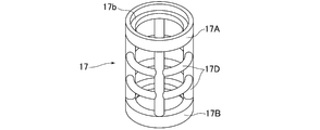
- FIG. 8 shows still another example of the spacer 17.
- the spacer 17 has a circular lattice structure made of an invar material such as invar, super invar, or stainless invar, and the wiring is drawn out in any direction of the spacer 17. be able to.
- the spacer 17 includes an annular upper member 17A, an annular lower member 17B arranged to face the upper member 17A, and a grid-like connecting member 17D that connects the upper member 17A and the lower member 17B. .
- the upper surface of the upper member 17A of the spacer 17 and the lower surface of the lower member 17B are stepped to closely fit the stepped base 16b of the upper piezoelectric actuator 16 and the stepped base 16b of the lower piezoelectric actuator 16.
- the spacer 17 and the upper and lower piezoelectric actuators 16 are positioned. Are arranged on a straight line.
- the piezoelectric element drive type valve 1 when a drive voltage is applied to the upper and lower two-stage piezoelectric actuators 16 from a control unit (not shown), the upper and lower two-stage piezoelectric actuators 16 correspond to the applied voltage. Extend upward by the set value. As a result, a large pushing force acts on the actuator box 12 via the spacer 17, the upper cradle 18, the thrust bearing 19, and the adjustment cap nut 20, and the actuator box 12 is held by the base presser 11 in the center thereof. Therefore, it rises by the set value against the elastic force of the elastic body 14. As a result, the elastic body 14 is separated from the valve seat 7c by the elastic force, and the piezoelectric element driven valve 1 is opened. The opening degree of the piezoelectric element driving valve 1 is adjusted by changing the voltage applied to the piezoelectric driving element 14.
- the upper and lower two-stage piezoelectric actuators 16 return to their original length from the extended state, and the actuator box 12 is pushed down by the elastic force of the elastic body 14. Then, the central part of the valve body 8 is pushed down to the valve seat 7c side by the diaphragm presser 13 provided at the lower end of the actuator box 12, and comes into contact with the valve seat 7c, so that the piezoelectric element driven valve 1 is closed.
- the piezoelectric element driven valve 1 has a configuration in which the two piezoelectric actuators 16 are stacked in a straight line up and down via a spacer 17 through which a wiring can be pulled out, so that the amount of displacement of the piezoelectric element can be increased. As a result, the stroke becomes larger and a large flow rate fluid can be controlled. Further, the piezoelectric element driven valve 1 can be assembled easily and easily because it is only necessary to stack two piezoelectric actuators 16 via the spacers 17. Furthermore, since the piezoelectric element drive type valve 1 has a configuration in which the spacer 17 can draw out the wiring, wiring is possible even if the two piezoelectric actuators 16 are stacked. And since the flow control apparatus provided with the piezoelectric element drive type valve
- the piezoelectric element driven valve 1 is used in a pressure control type flow control device.
- the piezoelectric element driven valve 1 is a thermal flow sensor. You may make it use for a thermal-type flow control apparatus.
- the piezoelectric element driven valve 1 is a normally closed type. However, in other embodiments, the piezoelectric element driven valve 1 may be a normally open type.
- a metal diaphragm is used for the valve body 8 of the piezoelectric element drive type valve 1.
- a valve body 8 other than the metal diaphragm is used. Also good.
- the two piezoelectric actuators 16 are stacked in a straight line with the spacer 17 interposed therebetween.
- three or more piezoelectric actuators 16 are spacers that can draw out wiring. 17 may be stacked on top and bottom in a straight line.
- the driving force of each piezoelectric actuator 16 is transmitted to the other piezoelectric actuator 16 via each spacer 17.
- the actuator box 12 is divided into three or more at the portion facing each spacer 17, and the divided three or more members can be detachably connected via the connecting body 12C. .
- the flow control device including the piezoelectric element driven valve 1 is used by being arranged in the vertical direction.
- the flow control including the piezoelectric element driven valve 1 is used.
- the device may be used in a horizontal orientation (horizontal posture).
- the two piezoelectric actuators 16 are arranged on a straight line through the spacer 17 in the front-rear direction or the left-right direction.
- 1 is a piezoelectric element driven valve
- 2 is an inlet side block
- 2a is an inlet side fluid passage
- 3 is a gasket
- 4 is an outlet side block
- 4a is an outlet side fluid passage
- 5 is a gasket type orifice
- 6 is a pressure sensor
- 7a is a fluid passage
- 7b is a recess
- 7c is a valve seat
- 8 is a valve body (metal diaphragm)
- 9 is a presser adapter
- 10 is a split base
- 10 ' is a cracked base piece
- 10a is a short cylindrical portion
- 10b 10c is an upper wall
- 10d is an insertion hole
- 10e is a fitting part
- 11 is a base retainer
- 11a is a flange part
- 12 is an actuator box
- 12A is a first cylinder part
- 12B is a second cylinder part
- 12C Is a
- 17A is an annular upper member
- 17B is an annular lower member
- 17C is a rod-like connecting member
- 17D is a lattice-like connecting member
- 18 is an upper receiving base
- 19 is a thrust bearing
- 20 is an adjustment cap nut
- 21 is a lock.
- Nut, 22 is a bolt
- 23 is an O-ring
- 24 is a control unit.
Landscapes
- Engineering & Computer Science (AREA)
- General Engineering & Computer Science (AREA)
- Mechanical Engineering (AREA)
- Physics & Mathematics (AREA)
- General Physics & Mathematics (AREA)
- Automation & Control Theory (AREA)
- Electrically Driven Valve-Operating Means (AREA)
Abstract
Description
特に、開口部又は切欠部を複数個形成したスペーサ、或いは、円形の柵構造又は円形の格子構造に形成したスペーサを用いた場合には、配線をスペーサのどの方向へも引き出すことができ、至極便利である。
図1は本発明の実施形態に係る圧電素子駆動式バルブ1を備えた流量制御装置を示し、当該流量制御装置は、圧電素子駆動式バルブ1と、圧電素子駆動式バルブ1の本体7の上流側にボルト(図示省略)により締め付け固定され、本体7の流体通路7aに連通する入口側流体通路2aを形成した入口側ブロック2と、本体7と入口側ブロック2との間に介設されたシール用のガスケット3と、圧電素子駆動式バルブ1の本体7の下流側にボルト(図示省略)により締め付け固定され、本体7の流体通路7aに連通する出口側流体通路4aを形成した出口側ブロック4と、本体7と出口側ブロック4との間に介設された流量制御用のガスケット型オリフィス5と、圧電素子駆動式バルブ1の本体7に配設され、ガスケット型オリフィス5の上流側の圧力を検出する圧力センサ6と、圧電素子駆動式バルブ1を制御する制御部(図示省略)等から構成されており、ガスケット型オリフィス5の上流側圧力によりオリフィス通過流量を演算しながら圧電素子駆動式バルブ1の開閉によりオリフィス通過流量を制御する圧力式の流量制御装置となっている。
また、図1に示す圧電素子駆動式バルブ1を備えた流量制御装置は、装置自体を縦向きに配置して使用している。
尚、金属ダイヤフラムの材質は、ステンレス鋼やインコネル、その他の合金鋼であっても良く、また、金属ダイヤフラムは、1枚の金属ダイヤフラムを使用するか、或いは、複数枚のダイヤフラムを積層した金属ダイヤフラムであっても良く、更に、金属ダイヤフラムの形状は、平板状であっても良い。
また、割りベース10を構成する二つの割りベース片10′は、短い円筒部10aと、円筒部10aの下端に連設されて本体7の凹部7b内に挿入される鍔部10bと、円筒部10aの上端に連設された上壁10cと、上壁10cに形成されてアクチュエータボックス12の周壁の一部が挿通される挿通孔10dと、上壁10cに連設されてアクチュエータボックス12の下端部周壁に形成したガイド穴12dに挿通され、アクチュエータボックス12の底壁12c上面に対向する嵌合部10eとをそれぞれ備えている。
更に、割りベース10の嵌合部10eとアクチュエータボックス12の底壁12cとの間には、アクチュエータボックス12を下方へ押圧附勢してダイヤフラム押え13を介して弁体8の中央部分を弁座7cへ当座させる複数枚の皿バネから成る弾性体14が介設されている。
このベース押え11は、ボルト22により本体7側へ起立姿勢で固定されており、アクチュエータボックス12を本体7側へ昇降自在に支持すると共に、弁体8の外周縁部、押えアダプター9及び割りベース10の鍔部10bを本体7側へ押圧固定するためのものである。
また、小径部12bの内方には、底壁12cが一体的に設けられており、底壁12cの上方空間に弾性体14及び下部受台15が収納され、底壁12cの下方空間にダイヤフラム押え13が挿入固定されている。
更に、大径部12aと小径部12bの境界部分の周壁には、割りベース10の嵌合部10eが挿入される縦長のガイド穴12dが対向状に形成されている。
そして、大径部12aの上端部外周面には、連結体12Cが着脱自在に螺着される雄ネジ12eが形成されている。
この第2筒部12Bの下端部外周面には、連結体12Cが着脱自在に螺着される雄ネジ12fが形成されていると共に、第2筒部12Bの上端部外周面には、調整用袋ナット20及びロックナット21が上下方向へ移動調整自在に螺着される雄ネジ12fが形成されている。
この連結体12Cの両端部内周面には、第1筒部12Aの雄ネジ12e及び第2筒部12Bの雄ネジ12fにそれぞれ着脱自在に螺着される雌ネジ12gが形成されていると共に、周壁には、配線を引き出せる開口部12hが形成されている。
尚、図1及び図4においては、連結体12Cの開口部12hを一つとしているが、連結体12Cの周壁に円周方向に沿って開口部12hを一定の間隔で複数個形成しても良い。この場合、配線を連結体12Cのどの方向へも引き出すことができる。
尚、下部受台15は、ステンレス材等の金属材により円盤状に形成されており、その上面中心部には、下段の圧電アクチュエータ16の半球状の変位部16dが位置決めされた状態で嵌合される円錐状の受溝が形成されている。
また、上段の圧電アクチュエータ16のリード端子16cは、下段の圧電アクチュエータ16のリード端子16cと同様にスペーサ17内に位置している。
尚、上部受台18は、ステンレス材等の金属材により円盤状に形成されており、その下面中心部には、上段の圧電アクチュエータ16の半球状の変位部16dが位置決めされた状態で嵌合される円錐状の受溝が形成されている。
また、スペーサ17の上端面及び下端面には、上段の圧電アクチュエータ16の段付きのベース16b及び下段の圧電アクチュエータ16の段付きのベース16bに緊密に嵌合する段付き部17bが形成されており、スペーサ17の上端部及び下端部を上下二段の圧電アクチュエータ16の段付きのベース16bに嵌め合せたときに、スペーサ17と上下二段の圧電アクチュエータ16とが軸心同士が一致するように位置決めされて一直線上に配置されるようになっている。
このスペーサ17は、複数個の開口部17aを備えているため、スペーサ17の開口部17aと連結体12Cの開口部12hとが合致し易くなると共に、配線をスペーサ17のどの方向へも引き出すことができる。
このスペーサ17は、環状の上部部材17Aと、上部部材17Aに対向状に配置された環状の下部部材17Bと、上部部材17Aと下部部材17Bとを連結する複数本の棒状連結部材17Cとを備えている。
また、スペーサ17の上部部材17Aの上面及び下部部材17Bの下面には、上段の圧電アクチュエータ16の段付きのベース16b及び下段の圧電アクチュエータ16の段付きのベース16bに緊密に嵌合する段付き部17bが形成されており、スペーサ17の上端部及び下端部を上下二段の圧電アクチュエータ16の段付きのベース16bに嵌め合せたときにスペーサ17と上下二段の圧電アクチュエータ16とが位置決めされて一直線上に配置されるようになっている。
このスペーサ17は、環状の上部部材17Aと、上部部材17Aに対向状に配置された環状の下部部材17Bと、上部部材17Aと下部部材17Bとを連結する格子状連結部材17Dとを備えている。
また、スペーサ17の上部部材17Aの上面及び下部部材17Bの下面には、上段の圧電アクチュエータ16の段付きのベース16b及び下段の圧電アクチュエータ16の段付きのベース16bに緊密に嵌合する段付き部17bが形成されており、スペーサ17の上端部及び下端部を上下二段の圧電アクチュエータ16の段付きのベース16bに嵌め合せたときにスペーサ17と上下二段の圧電アクチュエータ16とが位置決めされて一直線上に配置されるようになっている。
これにより、大きな押し上げ力がスペーサ17、上部受台18、スラストベアリング19及び調整用袋ナット20を介してアクチュエータボックス12に働き、当該アクチュエータボックス12がベース押え11にその軸心を保持された状態で弾性体14の弾性力に抗して上記設定値だけ上昇する。その結果、弾性体14がその弾性力によって弁座7cから離座し、圧電素子駆動式バルブ1は開弁状態となる。
尚、圧電素子駆動式バルブ1の開度は、ピエゾ駆動素子14への印加電圧を変動することにより調節されている。
また、圧電素子駆動式バルブ1は、二つの圧電アクチュエータ16をスペーサ17を介して積み重ねるだけで良いため、組み立てを簡単且つ容易に行える。
更に、圧電素子駆動式バルブ1は、スペーサ17が配線を引き出し可能な構成となっているため、二つの圧電アクチュエータ16を積み重ねても配線が可能となる。
そして、圧電素子駆動式バルブ1を備えた流量制御装置は、圧電アクチュエータ16を上下に積み重ねているため、大流量の流体を高精度で制御することができる。
Claims (11)
- 流体通路及び弁座を設けた本体と、本体の弁座に当離座して流体通路を開閉する弁体と、圧電素子の伸長を利用して前記弁体を開閉駆動する圧電アクチュエータとを備えた圧電素子駆動式バルブにおいて、少なくとも二つの圧電アクチュエータを、配線を引き出し可能なスペーサを介して一直線上に配設したことを特徴とする圧電素子駆動式バルブ。
- 少なくとも二つの圧電アクチュエータを一直線上に収容して支持する有底筒状のアクチュエータボックスを更に有し、当該アクチュエータボックスは、一方の圧電アクチュエータを収容する第1筒部と、他方の圧電アクチュエータを収容する第2筒部と、第1筒部と第2筒部とを着脱自在に連結して一方の圧電アクチュエータと他方の圧電アクチュエータとの間にスペーサの収容空間を形成する筒状の連結体とから成り、前記連結体に配線を引き出せる開口部を形成したことを特徴とする請求項1に記載の圧電素子駆動式バルブ。
- 弁体が自己弾性復帰型の金属ダイヤフラムにより形成されていると共に、アクチュエータボックスが本体側に移動自在に支持されており、アクチュエータボックスの基端部周壁を通過してアクチュエータボックスの底壁上面に対向する上壁を有する割りベースと、アクチュエータボックスの底壁と割りベースの上壁との間に介設されてアクチュエータボックスを弁座側へ押圧付勢して弁体を弁座へ当座させる弾性体とを備え、圧電アクチュエータが伸長したときに弾性体の弾性力に抗してアクチュエータボックスを移動させて前記弁体が弁座から離座することを特徴とする請求項2に記載の圧電素子駆動式バルブ。
- スペーサは、周壁に配線を引き出せる開口部又は切欠部を備えた円筒状に形成されていることを特徴とする請求項1、請求項2又は請求項3に記載の圧電素子駆動式バルブ。
- スペーサの周壁に、開口部又は切欠部を円周方向に一定の間隔で複数個形成したことを特徴とする請求項4に記載の圧電素子駆動式バルブ。
- スペーサは、配線を引き出せる円形の柵構造又は円形の格子構造に形成されていることを特徴とする請求項1、請求項2又は請求項3に記載の圧電素子駆動式バルブ。
- スペーサ及びアクチュエータボックスは、熱膨張係数が同じ材料により形成したことを特徴とする請求項2又は請求項3に記載の圧電素子駆動式バルブ。
- スペーサと、アクチュエータボックスの第1筒部、第2筒部及び連結体とをそれぞれ同じインバー材により形成したことを特徴とする請求項7に記載の圧電素子駆動式バルブ。
- 請求項1に記載の圧電素子駆動式バルブを備えた流量制御装置。
- 弁体より下流側の流体通路に配設されたオリフィスと、弁体とオリフィスの間の流体通路に配設された圧力センサと、圧力センサの検出値に基づいて一方の圧電アクチュエータ及び他方の圧電アクチュエータを制御する制御部とを更に有することを特徴とする請求項9に記載の流量制御装置。
- 弁体の上流側に配設した熱式の流量センサによって圧電アクチュエータを制御することを特徴とする請求項9に記載の流量制御装置。
Priority Applications (3)
| Application Number | Priority Date | Filing Date | Title |
|---|---|---|---|
| KR1020177000116A KR101910357B1 (ko) | 2014-09-01 | 2015-08-17 | 압전 소자 구동식 밸브 및 압전 소자 구동식 밸브를 구비한 유량 제어 장치 |
| CN201580039826.1A CN106687728B (zh) | 2014-09-01 | 2015-08-17 | 压电元件驱动式阀以及具备压电元件驱动式阀的流量控制装置 |
| US15/506,162 US10174858B2 (en) | 2014-09-01 | 2015-08-17 | Piezoelectric element-driven valve and flow rate control device including piezoelectric element-driven valve |
Applications Claiming Priority (2)
| Application Number | Priority Date | Filing Date | Title |
|---|---|---|---|
| JP2014177202A JP6475441B2 (ja) | 2014-09-01 | 2014-09-01 | 圧電素子駆動式バルブ及び圧電素子駆動式バルブを備えた流量制御装置 |
| JP2014-177202 | 2014-09-01 |
Publications (1)
| Publication Number | Publication Date |
|---|---|
| WO2016035262A1 true WO2016035262A1 (ja) | 2016-03-10 |
Family
ID=55439352
Family Applications (1)
| Application Number | Title | Priority Date | Filing Date |
|---|---|---|---|
| PCT/JP2015/004062 Ceased WO2016035262A1 (ja) | 2014-09-01 | 2015-08-17 | 圧電素子駆動式バルブ及び圧電素子駆動式バルブを備えた流量制御装置 |
Country Status (6)
| Country | Link |
|---|---|
| US (1) | US10174858B2 (ja) |
| JP (1) | JP6475441B2 (ja) |
| KR (1) | KR101910357B1 (ja) |
| CN (1) | CN106687728B (ja) |
| TW (1) | TWI598527B (ja) |
| WO (1) | WO2016035262A1 (ja) |
Families Citing this family (16)
| Publication number | Priority date | Publication date | Assignee | Title |
|---|---|---|---|---|
| JP6372998B2 (ja) * | 2013-12-05 | 2018-08-15 | 株式会社フジキン | 圧力式流量制御装置 |
| JP2017164121A (ja) * | 2016-03-15 | 2017-09-21 | 株式会社サンセイアールアンドディ | 遊技機 |
| KR102162045B1 (ko) * | 2016-12-26 | 2020-10-06 | 가부시키가이샤 후지킨 | 압전 소자 구동식 밸브 및 유량 제어 장치 |
| CN110999323A (zh) * | 2017-06-12 | 2020-04-10 | 晶致材料科技私人有限公司 | 经济高效、高弯曲刚度的连接器及其制成的压电致动器 |
| CN111373182A (zh) * | 2017-11-24 | 2020-07-03 | 株式会社富士金 | 阀装置以及使用该阀装置的控制装置的控制方法、流体控制装置以及半导体制造装置 |
| DE102018001048A1 (de) * | 2018-02-09 | 2019-08-14 | Atlas Copco Ias Gmbh | Dosierventil |
| SG11202100877QA (en) * | 2018-07-31 | 2021-03-30 | Fujikin Kk | Actuator, valve device, and fluid control apparatus |
| JP7166599B2 (ja) * | 2018-08-10 | 2022-11-08 | 株式会社フジキン | ダイヤフラムバルブおよび流量制御装置 |
| JP2020089037A (ja) * | 2018-11-22 | 2020-06-04 | 株式会社堀場エステック | ピエゾアクチュエータ、流体制御バルブ、及び、流体制御装置 |
| WO2020158459A1 (ja) * | 2019-01-31 | 2020-08-06 | 株式会社フジキン | バルブ装置、このバルブ装置を用いた流量制御方法、流体制御装置、半導体製造方法、および半導体製造装置 |
| JP7314559B2 (ja) * | 2019-03-25 | 2023-07-26 | 株式会社アドヴィックス | 車両の走行支援装置 |
| JP7001296B2 (ja) | 2020-01-08 | 2022-01-19 | 有限会社メカノトランスフォーマ | 変位拡大機構、アクチュエータ、研磨装置、電子部品処理装置、ディスペンサ、およびエアバルブ |
| JP7412747B2 (ja) * | 2020-01-30 | 2024-01-15 | 株式会社フジキン | 圧電素子駆動式バルブ、圧力式流量制御装置及び気化供給装置 |
| JP7335477B2 (ja) * | 2020-03-10 | 2023-08-30 | 株式会社オーエスエム | ポール型太陽光発電機、該ポール型太陽光発電機を備えた照明装置、及び該ポール型太陽光発電機を備えた監視情報通信装置 |
| JP7045738B1 (ja) * | 2021-03-23 | 2022-04-01 | 株式会社リンテック | 常時閉型流量制御バルブ |
| US20230235833A1 (en) | 2022-01-21 | 2023-07-27 | Hamilton Sundstrand Corporation | Flow control devices |
Citations (3)
| Publication number | Priority date | Publication date | Assignee | Title |
|---|---|---|---|---|
| JPH01203779A (ja) * | 1988-02-05 | 1989-08-16 | Toto Ltd | 単水路用の自動開閉弁 |
| JP2003534512A (ja) * | 2000-05-25 | 2003-11-18 | ローベルト ボツシユ ゲゼルシヤフト ミツト ベシユレンクテル ハフツング | 圧電式アクチエータ |
| JP2011117499A (ja) * | 2009-12-01 | 2011-06-16 | Fujikin Inc | 圧電駆動式バルブ及び圧電駆動式流量制御装置 |
Family Cites Families (12)
| Publication number | Priority date | Publication date | Assignee | Title |
|---|---|---|---|---|
| JPH0486367A (ja) * | 1990-07-30 | 1992-03-18 | Aisin Seiki Co Ltd | 燃料噴射弁 |
| US6170526B1 (en) * | 1999-05-18 | 2001-01-09 | Caterpillar Inc. | Piezoelectric actuated poppet valve to modulate pilot pressures and control main valve activation |
| US6345771B1 (en) * | 2000-06-30 | 2002-02-12 | Siemens Automotive Corporation | Multiple stack piezoelectric actuator for a fuel injector |
| JP4119109B2 (ja) | 2001-10-17 | 2008-07-16 | 株式会社フジキン | 圧電素子駆動式金属ダイヤフラム型制御弁 |
| JP4113425B2 (ja) | 2002-12-16 | 2008-07-09 | 株式会社フジキン | 圧電素子駆動式金属ダイヤフラム型制御弁 |
| JP4298476B2 (ja) | 2003-11-14 | 2009-07-22 | 株式会社フジキン | 流体制御装置 |
| DE102004009140B4 (de) * | 2004-02-25 | 2006-10-05 | Siemens Ag | Verfahren und Vorrichtung zur Polarisierung eines piezoelektrischen Aktors |
| JP4743763B2 (ja) | 2006-01-18 | 2011-08-10 | 株式会社フジキン | 圧電素子駆動式金属ダイヤフラム型制御弁 |
| CN100547899C (zh) * | 2006-12-15 | 2009-10-07 | 中国科学技术大学 | 双压电体线性纳米定位压电驱动器、其控制方法及控制器 |
| JP4933936B2 (ja) | 2007-03-30 | 2012-05-16 | 株式会社フジキン | 圧電素子駆動式制御弁 |
| JP5129609B2 (ja) | 2008-02-27 | 2013-01-30 | 株式会社フジキン | 圧電素子駆動式ダイヤフラム型制御弁 |
| GB0803899D0 (en) * | 2008-03-01 | 2008-04-09 | Mobrey Ltd | Vibrating element apparatus |
-
2014
- 2014-09-01 JP JP2014177202A patent/JP6475441B2/ja active Active
-
2015
- 2015-08-17 WO PCT/JP2015/004062 patent/WO2016035262A1/ja not_active Ceased
- 2015-08-17 US US15/506,162 patent/US10174858B2/en not_active Expired - Fee Related
- 2015-08-17 CN CN201580039826.1A patent/CN106687728B/zh not_active Expired - Fee Related
- 2015-08-17 KR KR1020177000116A patent/KR101910357B1/ko not_active Expired - Fee Related
- 2015-08-27 TW TW104128142A patent/TWI598527B/zh not_active IP Right Cessation
Patent Citations (3)
| Publication number | Priority date | Publication date | Assignee | Title |
|---|---|---|---|---|
| JPH01203779A (ja) * | 1988-02-05 | 1989-08-16 | Toto Ltd | 単水路用の自動開閉弁 |
| JP2003534512A (ja) * | 2000-05-25 | 2003-11-18 | ローベルト ボツシユ ゲゼルシヤフト ミツト ベシユレンクテル ハフツング | 圧電式アクチエータ |
| JP2011117499A (ja) * | 2009-12-01 | 2011-06-16 | Fujikin Inc | 圧電駆動式バルブ及び圧電駆動式流量制御装置 |
Also Published As
| Publication number | Publication date |
|---|---|
| KR101910357B1 (ko) | 2018-10-22 |
| CN106687728A (zh) | 2017-05-17 |
| US20170254430A1 (en) | 2017-09-07 |
| CN106687728B (zh) | 2019-08-27 |
| TW201619534A (zh) | 2016-06-01 |
| US10174858B2 (en) | 2019-01-08 |
| KR20170013982A (ko) | 2017-02-07 |
| JP2016050645A (ja) | 2016-04-11 |
| JP6475441B2 (ja) | 2019-02-27 |
| TWI598527B (zh) | 2017-09-11 |
Similar Documents
| Publication | Publication Date | Title |
|---|---|---|
| JP6475441B2 (ja) | 圧電素子駆動式バルブ及び圧電素子駆動式バルブを備えた流量制御装置 | |
| JP4933936B2 (ja) | 圧電素子駆動式制御弁 | |
| KR101001194B1 (ko) | 노말 오픈형의 압전소자 구동식 금속 다이어프램형 제어밸브 | |
| JP5775110B2 (ja) | 流量制御装置用の流量制御弁 | |
| TWI422765B (zh) | Piezoelectric drive valve and piezoelectric drive type flow control device | |
| US11054052B2 (en) | Piezoelectric-element-driven valve and flow rate control device | |
| TWI632766B (zh) | 壓電式線性致動器、壓電驅動閥及流量控制裝置 | |
| JP6194097B2 (ja) | 圧電式リニアアクチュエータ、圧電駆動バルブ、及び、流量制御装置 | |
| TWI576678B (zh) | Pressure flow control device | |
| TWI475168B (zh) | 流體控制器 | |
| JP7412747B2 (ja) | 圧電素子駆動式バルブ、圧力式流量制御装置及び気化供給装置 | |
| JP4951091B2 (ja) | 圧電素子駆動式金属ダイヤフラム型制御弁 | |
| JP2021119307A5 (ja) | ||
| KR102454097B1 (ko) | 밸브용 액추에이터와 이것을 구비한 다이아프램 밸브 |
Legal Events
| Date | Code | Title | Description |
|---|---|---|---|
| 121 | Ep: the epo has been informed by wipo that ep was designated in this application |
Ref document number: 15837826 Country of ref document: EP Kind code of ref document: A1 |
|
| ENP | Entry into the national phase |
Ref document number: 20177000116 Country of ref document: KR Kind code of ref document: A |
|
| WWE | Wipo information: entry into national phase |
Ref document number: 1020177000116 Country of ref document: KR |
|
| WWE | Wipo information: entry into national phase |
Ref document number: 15506162 Country of ref document: US |
|
| NENP | Non-entry into the national phase |
Ref country code: DE |
|
| 122 | Ep: pct application non-entry in european phase |
Ref document number: 15837826 Country of ref document: EP Kind code of ref document: A1 |