WO2016031279A1 - 積層造形用粉体及び積層造形体の製造方法 - Google Patents
積層造形用粉体及び積層造形体の製造方法 Download PDFInfo
- Publication number
- WO2016031279A1 WO2016031279A1 PCT/JP2015/057972 JP2015057972W WO2016031279A1 WO 2016031279 A1 WO2016031279 A1 WO 2016031279A1 JP 2015057972 W JP2015057972 W JP 2015057972W WO 2016031279 A1 WO2016031279 A1 WO 2016031279A1
- Authority
- WO
- WIPO (PCT)
- Prior art keywords
- powder
- layer
- layered
- metal powder
- sphericity
- Prior art date
Links
Images


Classifications
-
- B—PERFORMING OPERATIONS; TRANSPORTING
- B22—CASTING; POWDER METALLURGY
- B22F—WORKING METALLIC POWDER; MANUFACTURE OF ARTICLES FROM METALLIC POWDER; MAKING METALLIC POWDER; APPARATUS OR DEVICES SPECIALLY ADAPTED FOR METALLIC POWDER
- B22F1/00—Metallic powder; Treatment of metallic powder, e.g. to facilitate working or to improve properties
- B22F1/05—Metallic powder characterised by the size or surface area of the particles
- B22F1/052—Metallic powder characterised by the size or surface area of the particles characterised by a mixture of particles of different sizes or by the particle size distribution
-
- B—PERFORMING OPERATIONS; TRANSPORTING
- B22—CASTING; POWDER METALLURGY
- B22F—WORKING METALLIC POWDER; MANUFACTURE OF ARTICLES FROM METALLIC POWDER; MAKING METALLIC POWDER; APPARATUS OR DEVICES SPECIALLY ADAPTED FOR METALLIC POWDER
- B22F10/00—Additive manufacturing of workpieces or articles from metallic powder
- B22F10/20—Direct sintering or melting
- B22F10/28—Powder bed fusion, e.g. selective laser melting [SLM] or electron beam melting [EBM]
-
- B—PERFORMING OPERATIONS; TRANSPORTING
- B29—WORKING OF PLASTICS; WORKING OF SUBSTANCES IN A PLASTIC STATE IN GENERAL
- B29C—SHAPING OR JOINING OF PLASTICS; SHAPING OF MATERIAL IN A PLASTIC STATE, NOT OTHERWISE PROVIDED FOR; AFTER-TREATMENT OF THE SHAPED PRODUCTS, e.g. REPAIRING
- B29C67/00—Shaping techniques not covered by groups B29C39/00 - B29C65/00, B29C70/00 or B29C73/00
-
- B—PERFORMING OPERATIONS; TRANSPORTING
- B33—ADDITIVE MANUFACTURING TECHNOLOGY
- B33Y—ADDITIVE MANUFACTURING, i.e. MANUFACTURING OF THREE-DIMENSIONAL [3-D] OBJECTS BY ADDITIVE DEPOSITION, ADDITIVE AGGLOMERATION OR ADDITIVE LAYERING, e.g. BY 3-D PRINTING, STEREOLITHOGRAPHY OR SELECTIVE LASER SINTERING
- B33Y70/00—Materials specially adapted for additive manufacturing
- B33Y70/10—Composites of different types of material, e.g. mixtures of ceramics and polymers or mixtures of metals and biomaterials
-
- B—PERFORMING OPERATIONS; TRANSPORTING
- B22—CASTING; POWDER METALLURGY
- B22F—WORKING METALLIC POWDER; MANUFACTURE OF ARTICLES FROM METALLIC POWDER; MAKING METALLIC POWDER; APPARATUS OR DEVICES SPECIALLY ADAPTED FOR METALLIC POWDER
- B22F10/00—Additive manufacturing of workpieces or articles from metallic powder
- B22F10/30—Process control
- B22F10/32—Process control of the atmosphere, e.g. composition or pressure in a building chamber
-
- B—PERFORMING OPERATIONS; TRANSPORTING
- B22—CASTING; POWDER METALLURGY
- B22F—WORKING METALLIC POWDER; MANUFACTURE OF ARTICLES FROM METALLIC POWDER; MAKING METALLIC POWDER; APPARATUS OR DEVICES SPECIALLY ADAPTED FOR METALLIC POWDER
- B22F10/00—Additive manufacturing of workpieces or articles from metallic powder
- B22F10/30—Process control
- B22F10/34—Process control of powder characteristics, e.g. density, oxidation or flowability
-
- B—PERFORMING OPERATIONS; TRANSPORTING
- B33—ADDITIVE MANUFACTURING TECHNOLOGY
- B33Y—ADDITIVE MANUFACTURING, i.e. MANUFACTURING OF THREE-DIMENSIONAL [3-D] OBJECTS BY ADDITIVE DEPOSITION, ADDITIVE AGGLOMERATION OR ADDITIVE LAYERING, e.g. BY 3-D PRINTING, STEREOLITHOGRAPHY OR SELECTIVE LASER SINTERING
- B33Y80/00—Products made by additive manufacturing
-
- C—CHEMISTRY; METALLURGY
- C22—METALLURGY; FERROUS OR NON-FERROUS ALLOYS; TREATMENT OF ALLOYS OR NON-FERROUS METALS
- C22C—ALLOYS
- C22C32/00—Non-ferrous alloys containing at least 5% by weight but less than 50% by weight of oxides, carbides, borides, nitrides, silicides or other metal compounds, e.g. oxynitrides, sulfides, whether added as such or formed in situ
- C22C32/001—Non-ferrous alloys containing at least 5% by weight but less than 50% by weight of oxides, carbides, borides, nitrides, silicides or other metal compounds, e.g. oxynitrides, sulfides, whether added as such or formed in situ with only oxides
- C22C32/0015—Non-ferrous alloys containing at least 5% by weight but less than 50% by weight of oxides, carbides, borides, nitrides, silicides or other metal compounds, e.g. oxynitrides, sulfides, whether added as such or formed in situ with only oxides with only single oxides as main non-metallic constituents
-
- Y—GENERAL TAGGING OF NEW TECHNOLOGICAL DEVELOPMENTS; GENERAL TAGGING OF CROSS-SECTIONAL TECHNOLOGIES SPANNING OVER SEVERAL SECTIONS OF THE IPC; TECHNICAL SUBJECTS COVERED BY FORMER USPC CROSS-REFERENCE ART COLLECTIONS [XRACs] AND DIGESTS
- Y02—TECHNOLOGIES OR APPLICATIONS FOR MITIGATION OR ADAPTATION AGAINST CLIMATE CHANGE
- Y02P—CLIMATE CHANGE MITIGATION TECHNOLOGIES IN THE PRODUCTION OR PROCESSING OF GOODS
- Y02P10/00—Technologies related to metal processing
- Y02P10/25—Process efficiency
Definitions
- the additive manufacturing method using metal powder as a raw material is known as a method of directly obtaining a member having a three-dimensional shape.
- the method is roughly divided into a powder melting and laminating method in which the shape is obtained by locally melting, solidifying or sintering a powder (powder bed) previously formed into a layer with a heat source such as a laser or an electron beam, and a heat source while spraying the powder.
- the melt deposition method can be broadly divided into melting and solidification, and in any case, a three-dimensional laminated shaped body can be formed by melting, solidification or sintering of the powder.
- the flowability of the powder is required so as to form or spray the metal powder in layers, for example, in the additive manufacturing method of Patent Document 1, the powder surface is coated with a surfactant and the powder is used. It is disclosed to improve powder flowability by preventing body aggregation.
- the powders differ greatly in sphericity depending on the manufacturing method.
- the powder formed by the gas atomization method is close to a true sphere and is excellent in fluidity, but the powder formed by the water atomization method, electrolysis, crushing and the like tends to have a low sphericity.
- the flowability in the case of containing powder with low sphericity is not sufficiently considered.
- the configuration of the layered molding powder 100 used in the present embodiment is shown in FIG.
- the powder for laminate modeling of the present embodiment has a first metal powder having an average diameter of 10 ⁇ m to 200 ⁇ m and a sphericity higher than that of the first metal powder, and the metal powder having an average diameter of the first metal powder. It is a mixture of the second powder which is 1/10 or less of the body, the first metal powder occupies 99% or more of the volume fraction of the whole powder, and the second powder is less than 1% of the volume fraction It is.
- the sphericity is used as an index of the deviation of the shape from the most fluid sphericity. Specifically, it is represented by a ratio Rmin / Rmax of the minimum circumscribed spherical surface radius Rmax and the maximum inscribed spherical surface radius Rmin, with the center of the least mean square sphere of the powder surface as the center.
- the sphericity is 1, and it becomes an elliptical or flat shape, and when it is distorted from the sphere, this value becomes a lower value between 0 and 1.
- the material of the first metal powder 101 is selected in accordance with the layered object and the layered forming method described later.
- an alloy containing Al, Co, Cr, Fe, Ni, etc. is mentioned, and it is not particularly limited. Most of the powder for layered modeling 100 is occupied by the first metal powder 101, so the composition of the shaped object after shaping is almost the composition of the first metal powder 101.
- the first metal powder 101 used as the main component of the layered product is distorted and the sphericity is low, the first metal powder 101 described below is mixed to form the first metal.
- the flowability of the powder 101 can be enhanced, and the number of first metal powders 101 applicable to layered manufacturing can be increased.
- the average diameter of the first metal powder 101 is the arithmetic mean value of the maximum value and the minimum value of the measured diameter of one powder (the distance between two parallel planes in contact with the actual surface of one powder). .
- the sphericity of the first metal powder is preferably 0.4 or more.
- the powder can be produced by the atomizing method, melt spinning method, rotary electrode method, pulverizing method, reduction method, electrolysis method, chemical synthesis method, etc., depending on the material, diameter and production amount of the first metal powder 101 used. And be properly selected.
- the average diameter of the second powder 102 is 1/10 or less of that of the first metal powder 101, and the sphericity is higher than that of the first metal powder 101.
- the mean diameter of the second powder is defined in the same way as the mean diameter of the first powder.
- the addition amount of the second powder 102 is set to 0.001% or more and 1% or less of the volume fraction. If it is 0.001% or more, the effect of improving the flowability is sufficient, and if it is 1% or less, it is possible to suppress the rolling up and floating of the second powder 102.
- atomizing method melt spinning method, rotary electrode method, chemical synthesis method (sol gel method, suspension polymerization method, etc.) as a method of producing such powder, and the material, diameter and production amount of second powder 102 used It is selected appropriately according to the etc.
- the material of the second powder 102 various materials can be used including the same materials as the first metal powder 101, such as inorganic substances, metals, resin materials, etc. if the above conditions are satisfied. Highly sphericity oxides obtained by a melting method, a sol-gel method, etc., polymer fine particles obtained by a suspension polymerization method, etc. are suitably used.
- the first metal powder 101 when only the first metal powder 101 is melted using alumina or silica having a melting point higher than that of the first metal powder 101 to form a shaped object, fine dispersion with high sphericity also in the shaped object It is preferable because it can be distributed as a body to improve the strength and heat resistance.
- the first metal powder 101 and the second powder 102 are uniformly mixed by using a mixer, a homogenizer, a ball mill or the like to make a powder 100 for layered modeling. This mixing process may be performed at any stage before additive manufacturing.
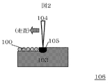
- the manufacturing method of the laminate-molded article 103 in the present embodiment is shown in FIG.
- the layered object 103 is formed by locally melting the layered forming powder 100 by the heating means 104 to form the melted portion 105 and then repeating the process of solidifying.
- the heating means 104 is scanned to melt and solidify the layered molding powder 100 at a desired position, thereby integrating with the surroundings and defining the shape of the layered molded body 103. This series of local melting and solidification processes are performed using the additive manufacturing apparatus 106.
- the prepared alloy powder 10 is spread on the surface to be shaped. That is, the alloy powder 10 is spread on the base material 15 placed on the layered modeling apparatus in the first powder spreading process in the layered modeling.
- the spread of the alloy powder 10 is, as shown in FIG. 3 (b), the recoater 23 forms the alloy powder 10 (see FIG. 3 (a)) supplied on the processing table 22 by the powder feeder (not shown). It can carry out by sweeping so that it may pass on the surface (base material 15), and laying the alloy powder 10 in thin layers.
- the expanded alloy powder 10 is locally heated and melted and then solidified, and the solidified layer is obtained by scanning the heated region by the local heating with respect to the plane on which the alloy powder 10 is expanded.
- Shape 40 According to two-dimensional shape information obtained from three-dimensional shape information (such as 3D-CAD data) representing the three-dimensional shape of the laminated structure to be manufactured, the formation of the solidified layer 40 (see FIG. It is carried out by scanning the heated region by the heating means 24.
- the local heating of the alloy powder 10 is carried out by limiting the heated region on the spread alloy powder 10 by the heating means 24 as shown in FIG. This is performed by selectively melting the part so that a minute molten pool (melting part 20) is formed.
- the size of the molten portion 20 formed by melting the alloy powder 10 is preferably 1 mm or less in diameter. By limiting the melting portion 20 to such a minute size, it is possible to enhance the shaping accuracy of the laminated structure and the uniformity of the elemental composition in the solidified structure.
- the region to be heated by the local heating of the alloy powder 10 is scanned so as to move parallel to the surface to be shaped, as shown in FIG.
- the scanning of the heated region can be performed by scanning the irradiation spot of the heat source with a galvano mirror or the like in addition to scanning of the main body of the heating means 24, and it is performed by an appropriate method such as raster scanning.
- overlap scanning with a plurality of radiation sources may be performed to flatten the irradiated energy density.
- melting and solidification of the alloy powder 10 are repeated on the base material 15 placed on the base material placement table 21 to form a set of solidification parts 30.
- a solidified layer 40 having a predetermined two-dimensional shape and thickness is formed.
- the unmelted alloy powder 10 remaining around or on the upper surface of the solidified layer 40 may be removed by air blasting.
- the substrate mounting table 21 is lowered by a height corresponding to the thickness of the formed solidified layer 40, and a new surface to be shaped of the upper surface of the solidified layer 40 and the processing table 22. Align so that it is flush with the upper surface of.
- the solidified layer shaping step is performed in the same manner as in FIGS. 3C to 3E, and the solidified layer 40 of the next layer is laminated.
- the solidified portion 30 to be laminated is integrated with a part of the lower solidified layer 40 to be densely sintered.
- the laminated structure having a desired shape and size can be layered and formed by repeating the powder spreading process and the solidified layer forming process in which the upper surface of the formed solidified layer 40 is a surface to be formed in the same manner.
- the sphericity of the silica fine particles having an average diameter of 12 ⁇ m (the electric and chemical industry) used in Comparative Examples 3 and 4 was 0.9 or more, as with the silica fine particles shown in Example 1.
- Example 6 to 10 copper powder (HEGANES Japan) formed by an electrolytic method was used as the first metal powder. The particle size was limited to those distributed from 50 ⁇ m to 100 ⁇ m, and those having an average diameter of about 60 ⁇ m were used.
- As the second powder alumina particles having an average diameter of 0.3 ⁇ m (Denki Kagaku Kogyo) were used.
- the laminated structures of Examples 1 to 10 obtained by applying the method of the present example were powders not containing the second powder shown in Comparative Examples 1 and 5.
- the flowability of the powder As shown in Tables 1 and 2, it was possible to reduce the voids in the powder before shaping, and as a result, it was possible to keep the porosity in the laminated shaped body at a low value.
- the dispersed second particles are contained in a trace amount in the structure of each material, and the effect of dispersion strengthening is expected.
Abstract
真球度の低い粉体を含んでも粉体の流動性を向上させる。 解決手段は以下の通りである。層状に敷き詰めた粉体にビームを照射して溶融させ、凝固層を形成することを繰り返して積層造形物を製造するために用いられる積層造形用粉体において、平均直径10μm以上200μm以下の第一の金属粉体を体積分率99%以上含み、前記第一の金属粉体よりも真球度が高く、平均直径が前記第一の金属粉体の1/10以下である第二の粉体を体積分率1%未満含むことを特徴とする積層造形用粉体。
Description
本発明は積層造形用粉体及び積層造形体の製造方法に関する。
金属粉体を原料とする積層造形法は3次元形状を有する部材を直接得られる手法として知られている。その方式は大別すると予め層状に形成した粉末(粉末床)をレーザ、電子線などの熱源により局所溶融・凝固または焼結する事によって形状を得る粉末溶融積層法と、粉末を噴射しながら熱源によって溶融・凝固する溶融堆積法に大別され、何れにおいても粉末の溶融・凝固または焼結により3次元積層造形体を形成する事ができる。
積層造形法では金属粉体を層状に形成する、または噴射すると言うように粉体の流動性が要求され、例えば特許文献1の積層造形法では、粉体表面を界面活性剤で被覆し、粉体の凝集を防ぐことで粉体の流動性を改善することが開示されている。
しかし、粉体は製法によって真球度が大きく異なる。ガスアトマイズ法により形成された粉体は真球に近く流動性に優れるが、水アトマイズ法や電気分解、破砕等により形成された粉体は真球度が低くなりやすい。上記特許文献では、真球度の低い粉体を含む場合の流動性を十分考慮していないという課題がある。
本発明の目的は、真球度の低い粉体を含んでも粉体の流動性を向上させることである。
上記目的を達成するために、例えば特許請求の範囲に記載の構成を採用する。
本発明によれば、真球度の低い粉体を含んでも粉体の流動性を向上させることができる。
以下、本発明の実施形態について、図面を参照しながらより詳細に説明する。なお、本発明はここで取り上げた実施形態に限定されることはなく、要旨を変更しない範囲で適宜組み合わせや改良が可能である。
本実施形態で用いる積層造形用粉体100の構成を図1に示す。本実施形態の積層造形用粉体は、平均直径が10μm以上200μm以下である第一の金属粉体と、第一の金属粉体よりも真球度が高く、平均直径が第一の金属粉体の1/10以下である第二の粉体の混合物であり、第一の金属粉体は全粉体の体積分率99%以上を占め、第二の粉体は体積分率1%未満である。
なお、本願では真球度を最も流動性の高い真球からの形状の狂いの指標として用いる。具体的には粉体表面の最小二乗平均球面の中心をその中心とする、最小外接球面半径Rmaxと最大内接球面半径Rminの比率Rmin/Rmaxにて表わす。完全な球では真球度は1であり、楕円状、扁平状のような形状となり球から歪んでいくと、この値は0と1の間でより低い値となる。
第一の金属粉体101の材質は、積層造形物や後に示す積層造形方法に合わせて選択する。例えば、Al、Co、Cr、Fe、Ni等を含む合金等が挙げられ特に限定されない。積層造形用粉体100のほとんどは第一の金属粉体101が占めるため、造形後の造形物の組成は、ほぼ第一の金属粉体101の組成となる。
本実施形態では、積層造形物の主成分として用いられる第一の金属粉体101がいびつで真球度が低い場合でも、以下で述べる第二の粉体102を混合することで第一の金属粉体101の流動性を高めることができ、積層造形に適用できる第一の金属粉体101を増やす事が出来る。
第一の金属粉体の平均直径は直径10μm以上200μm以下が好ましい。第一の粉体の平均直径が10μm以上であれば、合金粉末の巻き上がりや浮遊が抑制されたり、金属の酸化反応性が抑えられたりして、粉塵爆発等の恐れが低くなるためである。一方で、第一の粉体の平均直径が200μm以下であれば、積層造形において形成される凝固層の表面が平滑になり易い。凝固層の表面が平滑になると、凝固層上に粉体を敷き詰めやすくなる点で有利である。また、合金粉末を溶融させるための加熱手段の出力を抑えることが可能になり、合金粉末の溶融速度や合金粉末を局所加熱する際の被加熱領域の範囲の制御が容易になるため、合金構造体の造形精度や凝固組織の均一性を確保し易くすることができる。
第一の金属粉体101の平均直径とは、1つの粉体の実測直径(1つの粉体の実際の表面に接する平行二平面間の距離)の最大値と最小値の算術平均値とする。第一の金属粉体の真球度は0.4以上であることが好ましい。
粉末の製造方法はアトマイズ法、メルトスピニング法、回転電極法、粉砕法、還元法、電解法、化学合成法などがあり、用いる第一の金属粉体101の材質や直径、製造量等に応じて適切に選択される。
第二の粉体102の平均直径は第一の金属粉体101の1/10以下とし、真球度は第一の金属粉体101よりも高くする。第二の粉体の平均直径も第一の粉体の平均直径と同様に定義する。第二の粉体102の平均直径を第一の金属粉体101の1/10以下とすることで、第一の金属粉体101間に自然に存在する間隙に入り易くなる。間隙に入り込んだ第二の粉体102の真球度が第一の金属粉体101よりも高いことで、第二の粉体102が第一の金属粉体101間の摩擦を軽減し、第一の金属粉体101が滑りやすくなり、流動性を改良することができる。
第二の粉体102の真球度は、0.8以上1以下であることが好ましい。真球度が0.8以上であれば、第一の金属粉体101の間隙に第二の粉体102が侵入した際に真球度の高い第二の粉体102の転がりの作用が顕著に現れて摩擦を軽減するために好適である。また、第二の粉体102がセラミックスであると、表面が滑らかな粉体を形成しやすいため、第一の金属粉体101の流動性の改良には好ましい。
第二の粉体102の添加量は、体積分率0.001%以上1%以下とする。0.001%以上であれば、流動性の改良効果が十分であり、1%以下であれば、第二の粉体102の巻き上がりや浮遊を抑制することができる。
このような粉末の製造方法にはアトマイズ法、メルトスピニング法、回転電極法、化学合成法(ゾルゲル法、懸濁重合法など)があり、用いる第二の粉体102の材質や直径、製造量等に応じて適切に選択される。第二の粉体102の材質としては上記の条件を満たせば、無機物、金属、樹脂材料など、第一の金属粉体101と同一の材料を含めて様々な材料を用いることが出来るが、例えば溶融法やゾルゲル法などにより得られる高真球度酸化物、懸濁重合法により得られる高分子微粒子などが好適に用いられる。特に、第一の金属粉体101よりも融点の高いアルミナやシリカを用いて第一の金属粉体101だけを溶融させて造形物を形成すると、造形物中にも真球度の高い微細分散体として分布して強度や耐熱性を改善する効果も得られるために好適である。
第一の金属粉体101と第二の粉体102はミキサ、ホモジェナイザ、ボールミルなどを用いて均一に混合することで積層造形用粉体100とする。この混合工程は積層造形前の何れかの段階で施せば良い。
本実施形態における積層造形体103の製造方法を、粉末溶融積層法を例として図2に示す。積層造形体103は積層造形用粉体100を加熱手段104によって局所溶融して溶融部105を形成し、その後に凝固すると言う工程を繰り返すことで形成する。加熱手段104を走査して、所望の位置にある積層造形用粉体100を溶融、凝固することで周囲と一体化し、積層造形体103の形状を規定する。この一連の局所溶融、凝固プロセスは積層造形装置106を用いて行う。
本実施形態における積層造形体103の製造方法を工程ごとに分けて図3に示す。
本実施形態に係る積層造形体の製造方法では、図3(a)から(g)に順に示す積層造形工程を繰り返し行って積層造形体の立体造形を行う。積層造形工程は、従来から一般的に利用されている金属用の粉末積層造形装置を用いて行うことが可能である。粉末調製工程で調製された第一の金属粉体101と第二の粉体102の混合物(合金粉末10)は、このような積層造形工程の原料粉末として用いられる。積層造形装置に備えられる加熱手段としては、例えば、電子線加熱、レーザ加熱、マイクロ波加熱、プラズマ加熱、集光加熱、高周波加熱等の適宜のビームの加熱原理によるものが用いられる。これらの中では電子線加熱又はレーザ加熱による積層造形装置が特に好適である。電子線加熱又はレーザ加熱によると、熱源の出力や、合金粉末10の被加熱領域の微小化や、積層構造体の造形精度等の制御を比較的容易に行えるためである。
積層造形工程は、詳細には、粉末展延工程、凝固層造形工程を含んでなる。積層造形工程では、図3(a)から(g)に順に示されるような工程を経て、層状の凝固組織(凝固層)を形成し、層状の凝固組織(凝固層)の形成を繰り返すことで、凝固組織の集合からなる積層構造体を造形する。
積層造形装置には、図3(a)に示すように、上端に基材載置台21を有する昇降可能なピストンが備えられている。この基材載置台21の周囲には、ピストンに連動しない加工テーブル22が備えられており、加工テーブル22上に合金粉末10を供給する不図示の粉末フィーダ、供給された合金粉末10を展延するリコータ23、合金粉末10を加熱する加熱手段24が備えられている。加工テーブル22上の合金粉末10を除去するエアブラスト、調温器等を備えていてもよい。加工テーブル22やこれらの機器類は、チャンバに収容されており、チャンバ内の雰囲気は、加熱手段24の種類に応じて真空雰囲気又はアルゴンガス等の不活性ガス雰囲気とされ、雰囲気圧力や温度が管理されるようになっている。積層造形を行うに際しては、基材載置台21にあらかじめ基材15が載置され、基材15の被造形面(上面)と加工テーブル22の上面とが面一となるように位置合わせされる。
基材15としては、加熱手段24による加熱に対する耐熱性を備えていれば適宜の材料を用いることができる。この積層構造体の製造方法においては、基材15の被造形面上に対して積層構造体の積層造形が行われることで、基材15と積層構造体とが一体化した状態の造形物が得られることになる。そのため、基材15としては、切断加工等により積層構造体から分離することを想定して、平板状等の適宜の形状の基材15を用いることができる。或いは、基材15と積層構造体とを一体化した状態で機能させることを想定して、被造形面を有する任意形状の構造部材、機構部材等を基材15として用いることもできる。
粉末展延工程では、調製された合金粉末10を被造形面上に展延する。すなわち、積層造形における初回の粉末展延工程では、積層造形装置に載置された基材15に合金粉末10を展延する。合金粉末10の展延は、図3(b)に示すように、不図示の粉末フィーダによって加工テーブル22上に供給された合金粉末10(図3(a)参照)を、リコータ23が被造形面(基材15)上を通過するように掃引して、合金粉末10を薄層状に敷き詰めることによって行うことができる。本実施形態の合金粉末10は、積層構造体の主成分となる第一の金属粉体の真球度が低くても、この第一の金属粉体を滑りやすくする第二の粉体が混合されているので、第一の金属粉体のみの場合よりも展延し易くなる。形成される合金粉末10の薄層の厚さは、合金粉末10を溶融させる加熱手段の出力や、合金粉末10の平均粒子径等に応じて適宜調節することができるが、好ましくは10μm以上1000μm以下程度の範囲とする。
凝固層造形工程では、展延された合金粉末10を局所加熱して溶融させた後に凝固させ、局所加熱による被加熱領域を合金粉末10が展延された平面に対して走査することによって凝固層40を造形する。後記の凝固層40(図3(e)参照)の造形は、製造しようとする積層構造体の立体形状を表す3次元形状情報(3D-CADデータ等)から得られる2次元形状情報にしたがって、加熱手段24による被加熱領域を走査することで行われる。
合金粉末10の局所加熱は、図3(c)に示すように、加熱手段24によって、展延された合金粉末10上の被加熱領域を限定して行い、展延された合金粉末10の一部を微小な溶融池(溶融部20)が形成されるように選択的に溶融させることにより行う。合金粉末10を溶融させて形成する溶融部20の大きさは、好ましくは直径1mm以下とする。溶融部20をこのような微小な大きさに制限することで、積層構造体の造形精度や、凝固組織における元素組成の均一性が高められるようになる。
合金粉末10の局所加熱による被加熱領域は、図3(d)に示すように、被造形面に平行に移動するように走査させる。被加熱領域の走査は、加熱手段24の本体の走査のほか、ガルバノミラー等による熱源の照射スポットの走査により行うことも可能であり、ラスター走査のような適宜の方式で実施する。このとき、複数の線源によるオーバーラップ走査を行い、照射されるエネルギ密度を平坦化させてもよい。そして、被加熱領域の走査によって、合金粉末10が未だ溶融していない領域の局所加熱を新たに行うと共に、合金粉末10が既に溶融して溶融部20が形成された領域の加熱を止めて、溶融部20を雰囲気温度の下で冷却して凝固させる。溶融部20が凝固することで形成される凝固部30は、基材や既に形成されている凝固部30と一体化しつつ凝固部30の緻密な集合を形成することになる。
加熱手段24の走査速度、出力、エネルギ密度、走査幅は、合金粉末10の元素組成、粒度分布、基材15の材質、溶融部20と凝固部30との位置関係、チャンバ温度等から推定される熱伝導や熱放射に基いて適宜調整すればよい。また、溶融部20を冷却する冷却温度は、積層構造体の元素組成に応じて寸法変化、熱歪等を考慮して設定すればよい。溶融部20の大きさや、溶融速度や、冷却速度や、溶融及び冷却の時間間隔等を所定の範囲に維持して走査を行うことによって、造形される積層構造体の強度分布を均一化したり、残留応力や表面粗さを低減させたりすることが可能である。
図3(c)から(e)に示すように、基材載置台21に載置された基材15上で、合金粉末10の溶融と凝固とを繰り返し凝固部30の集合を形成することで、所定の2次元形状と厚さとを有する凝固層40が形成される。凝固層40の形成後、凝固層40の周囲や上面に残存している未溶融の合金粉末10をエアブラストによって除去してもよい。図3(f)に示すように、基材載置台21を、形成された凝固層40の厚さに相当する高さ下降させて、凝固層40の上面の新たな被造形面と加工テーブル22の上面とが面一となるように位置合わせする。
位置合わせを行った後、図3(a)から(b)と同様にして粉末展延工程を行い、図3(g)に示すように、既に形成されている凝固層40の上面に新たに供給された合金粉末10を展延する。2回目以降の粉末展延工程は、既に展延された粉末上または凝固層上で行われる。これらは基板よりも表面の凹凸が大きくなるため、真球度が低い第一の金属粉体はその凹凸に引っ掛かり易くなるが、本実施形態では第二の粉体が混合されているので第一の金属粉体は滑りやすくなり、第一の金属粉体のみの場合よりも展延し易くなる。
その後、図3(c)から(e)と同様にして凝固層造形工程を行い、次層の凝固層40の積層を行う。積層される凝固部30は下層の凝固層40の一部と一体化して緻密に焼結することになる。以降、同様にして、形成された凝固層40の上面を被造形面とした粉末展延工程及び凝固層造形工程を繰り返すことで、所望の形状寸法の積層構造体を積層造形することができる。
このような積層造形工程を繰り返し行って立体造形を行う積層構造体の製造方法によれば、積層構造体を微小な凝固組織の集合によって所望の形状寸法で製造することができる。また、微小な凝固組織(凝固部30)のそれぞれの元素組成は、用いた合金粉末の元素組成を良好に反映しているため、元素組成分布の均一性及び機械的強度の分布の均一性が高い固溶相を形成することができる。さらには、一方向からの加熱によって凝固組織(凝固部30)を形成し、結晶成長方向が略一方向に配向した凝固組織(凝固層40)を積層することができるため、異方性が高い積層構造体を形成することができる。
本実施形態にて開示する積層造形体103は積層造形用粉体100の流動性が改善されるために造形精度に優れる。また、第二の粉体102の少なくとも一部が第一の金属粉体101が溶解・焼結されて生成する金属組織中の微細分散体として存在するため、高温強度や疲労強度に優れた造形体とすることができる。このような特性は各種機械部品、金型、医療用インプラントなど様々な用途に好適であり、各部材の寸法精度や強度の改善に寄与することができる。
以下、図面を用いて実施例及び比較例を説明する。
(実施例)
実施例1~5は、第一の金属粉体にアトマイズ法で形成したステンレス粉(SUS316L粉末、ヘガネスジャパン)を用いた。粒径が50μmから100μmに分布するものに限定し、平均直径が約70μmのものを使用した。第二の粉体には平均直径約0.03μmのシリカ微粒子(日本アエロジル)を用いた。真球度は第一の金属粉体の平均値が約0.7、第二の粉体が約0.8であり、第二の粉体の平均直径は第一の金属粉体の1/10よりも小さく、真球度は優れていることを確認した。第一の金属粉体と第二の粉体を表1に示す体積分率で混合し、Vミキサによって1時間攪拌することで積層造形用粉体とした。
(実施例)
実施例1~5は、第一の金属粉体にアトマイズ法で形成したステンレス粉(SUS316L粉末、ヘガネスジャパン)を用いた。粒径が50μmから100μmに分布するものに限定し、平均直径が約70μmのものを使用した。第二の粉体には平均直径約0.03μmのシリカ微粒子(日本アエロジル)を用いた。真球度は第一の金属粉体の平均値が約0.7、第二の粉体が約0.8であり、第二の粉体の平均直径は第一の金属粉体の1/10よりも小さく、真球度は優れていることを確認した。第一の金属粉体と第二の粉体を表1に示す体積分率で混合し、Vミキサによって1時間攪拌することで積層造形用粉体とした。
レーザ溶融積層造形装置(EOS社 M270)に積層造形用粉体と基材(100mm×100mm×10mmの炭素鋼(S45C)板材)を組み込み、積層造形用粉体の供給、窒素雰囲気下でレーザからなる加熱手段104による局所溶融と凝固、冷却を繰り返すことで円筒状(直径10mm、高さ50mm)の積層造形体を形成した。その後、基材から積層造形体を切断した。
(比較例)
比較例1は第二の粉体を混合しておらず、比較例2~4は、第二の粉体の平均直径と第二の粉体の体積分率(混合比)が実施例1と異なる。その他の条件は実施例1と同一とした。なお、比較例3,4で用いた平均直径12μmのシリカ微粒子(電気化学工業)の真球度は実施例1に示したシリカ微粒子と同じく0.9以上であった。
(実施例)
実施例6~10では第一の金属粉体に電解法で形成した銅粉末(へガネスジャパン)を用いた。粒径が50μmから100μmに分布するものに限定し、平均直径が約60μmのものを使用した。第二の粉体には平均直径0.3μmのアルミナ粒子(電気化学工業)を用いた。真球度は第一の金属粉体の平均値が約0.4、第二の粉体が約0.9であり、第二の粉体の直径は第一の金属粉体の1/10よりも小さく、真球度は優れていることを確認した。第一の金属粉体と第二の粉体を表2に示す体積分率で混合し、Vミキサによって1時間攪拌することで積層造形用粉体とした。
レーザ溶融積層造形装置(EOS社 M270)に積層造形用粉体と基材(100mm×100mm×10mmの炭素鋼(S45C)板材)を組み込み、積層造形用粉体の供給、窒素雰囲気下でレーザからなる加熱手段による局所溶融と凝固、冷却を繰り返すことで円筒状(直径10mm、高さ50mm)の積層造形体を形成した。その後、基材から積層造形体を切断した。
(比較例)
比較例5は第二の粉体を混合しておらず、比較例6は、実施例6に用いた第一の金属粉体と第二の粉体の混合比を表1に示すように設定し、その他の実施形態は実施例6と同一とした。
(結果の比較)
各実施例、比較例で得られた各積層造形体を中心線を通る面にて切断し、得られた断面において観察された空隙率と第二の粒子の体積分率とを表1に示す。第二の粉体の体積分率は、第二の粉体が造形体中に均一に分散すると仮定し、前記断面における第二の粉体の面積分率の値を用いた。なお、実施例1-5、比較例2では第二の粉体の平均直径が0.03μmと小さく、比較例3,4では第二の粉体が均一には分散しなかったため、積層造形体中の第二の粉体の体積率を評価していない。積層造形体空隙率は5%未満に抑制できた場合を良、それ以外を不良と判定した。


表1、2に示されたように、本実施例の手法を適用して得た実施例1から10の積層構造体は、比較例1、5に示した第二の粉体を含まない粉体と比較して粉体の流動性が改善することで造形前の粉体における空隙を低減し、結果として積層造形体における空隙率を低い値に収める事が出来た。また、各材料の組織中には分散した第二の粒子が微量に含まれており、分散強化の効果が期待される。
一方、比較例2,6に示したように第二の粉体を1%以上含めた条件では空隙率が増加した。第二の粉体の比重が第一の金属粉体よりも低いために、第二の粉体を過剰に用いると、粉体供給時に積層造形粉体の粉体上部に浮き上がり、造形時にまきあげ効果によって欠損部を生じるものと考えられる。また、比較例3,4に示すように第二の粉体が第一の金属粉体の直径の1/10よりも大きい場合には第一の金属粉体の粉体間に第二の粉体が一様に入らず、空隙率は増加することが判った。以上のように、本実施例に示した積層造形用粉体は積層構造体の造形精度を改善し、積層構造体中に強化層として有効な微粒子分散体を形成できることが確認された
10 合金粉末
15 基材
20 溶融部
21 基材載置台
22 加工テーブル
23 リコータ
24 加熱手段
30 凝固部
40 凝固層
100 積層造形用粉体
101 第一の金属粉体
102 第二の粉体
103 積層造形体
104 加熱手段
105 溶融部
106 積層造形装置
107 凝固部
108 基材
109 非溶融部
15 基材
20 溶融部
21 基材載置台
22 加工テーブル
23 リコータ
24 加熱手段
30 凝固部
40 凝固層
100 積層造形用粉体
101 第一の金属粉体
102 第二の粉体
103 積層造形体
104 加熱手段
105 溶融部
106 積層造形装置
107 凝固部
108 基材
109 非溶融部
Claims (6)
- 層状に敷き詰めた粉体にビームを照射して溶融させ、凝固層を形成することを繰り返して積層造形物を製造するために用いられる積層造形用粉体において、
平均直径10μm以上200μm以下の第一の金属粉体を体積分率99%以上含み、
前記第一の金属粉体よりも真球度が高く、平均直径が前記第一の金属粉体の1/10以下である第二の粉体を体積分率1%未満含むことを特徴とする積層造形用粉体。 - 請求項1において、前記第二の粉体の真球度が0.8以上であることを特徴とする積層造形用粉体。
- 請求項1において、前記第二の粉体がセラミックスであることを特徴とする積層造形用粉体。
- 請求項1において、前記第二の粉体がシリカ又はアルミナであることを特徴とする積層造形用粉体。
- 請求項1において、前記第一の金属粉体の真球度が0.4以上であることを特徴とする積層造形用粉体。
- 平均直径10μm以上200μm以下の第一の金属粉体を体積分率99%以上含み、前記第一の金属粉体よりも真球度が高く、平均直径が前記第一の金属粉体の1/10以下である第二の粉体を体積分率1%未満含む積層造形用粉体を層状に敷き詰める工程と、
敷き詰められた前記積層造形用粉体にビームを照射して溶融部を形成し、前記溶融部を凝固させ凝固層を形成する工程と、を備え、
前記積層造形用粉体を層状に敷き詰める工程と前記凝固層を形成する工程とを繰り返して複数の層状の凝固層を形成することを特徴とする積層造形物の製造方法。
Priority Applications (2)
| Application Number | Priority Date | Filing Date | Title |
|---|---|---|---|
| JP2016544976A JP6303016B2 (ja) | 2014-08-27 | 2015-03-18 | 積層造形物の製造方法 |
| EP15835169.2A EP3187285B1 (en) | 2014-08-27 | 2015-03-18 | Powder for layer-by-layer additive manufacturing, and process for producing object by layer-by-layer additive manufacturing |
Applications Claiming Priority (2)
| Application Number | Priority Date | Filing Date | Title |
|---|---|---|---|
| JP2014172169 | 2014-08-27 | ||
| JP2014-172169 | 2014-08-27 |
Publications (1)
| Publication Number | Publication Date |
|---|---|
| WO2016031279A1 true WO2016031279A1 (ja) | 2016-03-03 |
Family
ID=55399186
Family Applications (1)
| Application Number | Title | Priority Date | Filing Date |
|---|---|---|---|
| PCT/JP2015/057972 WO2016031279A1 (ja) | 2014-08-27 | 2015-03-18 | 積層造形用粉体及び積層造形体の製造方法 |
Country Status (3)
| Country | Link |
|---|---|
| EP (1) | EP3187285B1 (ja) |
| JP (1) | JP6303016B2 (ja) |
| WO (1) | WO2016031279A1 (ja) |
Cited By (8)
| Publication number | Priority date | Publication date | Assignee | Title |
|---|---|---|---|---|
| CN106925786A (zh) * | 2017-03-29 | 2017-07-07 | 西北工业大学 | 基于均匀金属液滴喷射的多粒径均匀球形粉体批量制备装置与方法 |
| JP2017179388A (ja) * | 2016-03-28 | 2017-10-05 | 大同特殊鋼株式会社 | 焼結用粉末および焼結体 |
| WO2017195695A1 (ja) * | 2016-05-11 | 2017-11-16 | 日立金属株式会社 | 複合部材の製造方法及び複合部材 |
| WO2019038910A1 (ja) * | 2017-08-25 | 2019-02-28 | 福田金属箔粉工業株式会社 | 積層造形用粉末の評価方法およびその積層造形用粉末 |
| JP2021075789A (ja) * | 2019-11-07 | 2021-05-20 | コミッサリア ア レネルジー アトミーク エ オ ゼネルジ ザルタナテイヴ | 最適化された鋼材料 |
| CN114888311A (zh) * | 2022-04-18 | 2022-08-12 | 西安赛隆金属材料有限责任公司 | 一种粉床电子束增材制造装置及方法 |
| US11534824B2 (en) | 2018-03-15 | 2022-12-27 | Hewlett-Packard Development Company, L.P. | Composition |
| JP7395840B2 (ja) | 2019-04-09 | 2023-12-12 | セイコーエプソン株式会社 | 積層造形用粉末および積層造形体の製造方法 |
Families Citing this family (6)
| Publication number | Priority date | Publication date | Assignee | Title |
|---|---|---|---|---|
| CA3065828A1 (en) | 2017-05-31 | 2018-12-06 | Smith International, Inc. | Cutting tool with pre-formed hardfacing segments |
| US10960607B2 (en) | 2018-12-13 | 2021-03-30 | General Electric Company | Systems and methods for monitoring powder spreading in additive manufacturing systems |
| US20220219232A1 (en) * | 2019-06-13 | 2022-07-14 | Fukuda Metal Foil & Powder Co.,Ltd. | Laminating and shaping copper powder, laminated and shaped object, manufacturing method of laminated and shaped object, and laminating and shaping apparatus |
| US20220388059A1 (en) * | 2019-11-08 | 2022-12-08 | Daido Steel Co., Ltd. | Powder material |
| DE102020000501A1 (de) | 2020-01-27 | 2021-07-29 | Eos Gmbh Electro Optical Systems | Passivierung von Filterrückständen |
| DE102020102628A1 (de) * | 2020-02-03 | 2021-08-05 | Eos Gmbh | Verfahren zur Moderation einer Reaktion von Metallpartikeln |
Citations (2)
| Publication number | Priority date | Publication date | Assignee | Title |
|---|---|---|---|---|
| JP2010202928A (ja) * | 2009-03-03 | 2010-09-16 | Hyogo Prefecture | 金属造形物の製造方法及び積層造形用の金属樹脂複合体粉末 |
| JP2011184708A (ja) * | 2010-03-04 | 2011-09-22 | Kobe Steel Ltd | 粉末冶金用混合粉末 |
Family Cites Families (2)
| Publication number | Priority date | Publication date | Assignee | Title |
|---|---|---|---|---|
| JP4947659B2 (ja) * | 2008-02-29 | 2012-06-06 | 福田金属箔粉工業株式会社 | 銅系金属粉末 |
| JP2011021218A (ja) * | 2009-07-14 | 2011-02-03 | Kinki Univ | 積層造形用粉末材料及び粉末積層造形法 |
-
2015
- 2015-03-18 WO PCT/JP2015/057972 patent/WO2016031279A1/ja active Application Filing
- 2015-03-18 JP JP2016544976A patent/JP6303016B2/ja active Active
- 2015-03-18 EP EP15835169.2A patent/EP3187285B1/en active Active
Patent Citations (2)
| Publication number | Priority date | Publication date | Assignee | Title |
|---|---|---|---|---|
| JP2010202928A (ja) * | 2009-03-03 | 2010-09-16 | Hyogo Prefecture | 金属造形物の製造方法及び積層造形用の金属樹脂複合体粉末 |
| JP2011184708A (ja) * | 2010-03-04 | 2011-09-22 | Kobe Steel Ltd | 粉末冶金用混合粉末 |
Non-Patent Citations (1)
| Title |
|---|
| See also references of EP3187285A4 * |
Cited By (17)
| Publication number | Priority date | Publication date | Assignee | Title |
|---|---|---|---|---|
| JP2017179388A (ja) * | 2016-03-28 | 2017-10-05 | 大同特殊鋼株式会社 | 焼結用粉末および焼結体 |
| WO2017195695A1 (ja) * | 2016-05-11 | 2017-11-16 | 日立金属株式会社 | 複合部材の製造方法及び複合部材 |
| CN109153079A (zh) * | 2016-05-11 | 2019-01-04 | 日立金属株式会社 | 复合部件的制造方法和复合部件 |
| US11786967B2 (en) | 2016-05-11 | 2023-10-17 | Proterial, Ltd. | Composite member manufacturing method and composite member |
| JPWO2017195695A1 (ja) * | 2016-05-11 | 2019-04-04 | 日立金属株式会社 | 複合部材の製造方法及び複合部材 |
| EP3456440A4 (en) * | 2016-05-11 | 2020-01-08 | Hitachi Metals, Ltd. | ASSEMBLY PROCESS AND ASSEMBLY |
| CN106925786A (zh) * | 2017-03-29 | 2017-07-07 | 西北工业大学 | 基于均匀金属液滴喷射的多粒径均匀球形粉体批量制备装置与方法 |
| CN106925786B (zh) * | 2017-03-29 | 2019-02-19 | 西北工业大学 | 基于均匀金属液滴喷射的多粒径均匀球形粉体批量制备装置与方法 |
| JPWO2019038910A1 (ja) * | 2017-08-25 | 2020-10-01 | 福田金属箔粉工業株式会社 | 積層造形用粉末の評価方法およびその積層造形用粉末 |
| US11644397B2 (en) | 2017-08-25 | 2023-05-09 | Fukuda Metal Foil & Powder Co., Ltd. | Lamination shaping powder evaluation method and lamination shaping powder therefor |
| WO2019038910A1 (ja) * | 2017-08-25 | 2019-02-28 | 福田金属箔粉工業株式会社 | 積層造形用粉末の評価方法およびその積層造形用粉末 |
| US11534824B2 (en) | 2018-03-15 | 2022-12-27 | Hewlett-Packard Development Company, L.P. | Composition |
| US11684978B2 (en) | 2018-03-15 | 2023-06-27 | Hewlett-Packard Development Company, L.P. | Build material composition |
| JP7395840B2 (ja) | 2019-04-09 | 2023-12-12 | セイコーエプソン株式会社 | 積層造形用粉末および積層造形体の製造方法 |
| JP2021075789A (ja) * | 2019-11-07 | 2021-05-20 | コミッサリア ア レネルジー アトミーク エ オ ゼネルジ ザルタナテイヴ | 最適化された鋼材料 |
| JP7325393B2 (ja) | 2019-11-07 | 2023-08-14 | コミッサリア ア レネルジー アトミーク エ オ ゼネルジ ザルタナテイヴ | 最適化された鋼材料 |
| CN114888311A (zh) * | 2022-04-18 | 2022-08-12 | 西安赛隆金属材料有限责任公司 | 一种粉床电子束增材制造装置及方法 |
Also Published As
| Publication number | Publication date |
|---|---|
| JP6303016B2 (ja) | 2018-03-28 |
| JPWO2016031279A1 (ja) | 2017-04-27 |
| EP3187285A1 (en) | 2017-07-05 |
| EP3187285B1 (en) | 2023-07-05 |
| EP3187285A4 (en) | 2018-05-02 |
Similar Documents
| Publication | Publication Date | Title |
|---|---|---|
| WO2016031279A1 (ja) | 積層造形用粉体及び積層造形体の製造方法 | |
| US20220266511A1 (en) | Additive manufacturing material for powder rapid prototyping manufacturing | |
| TWI677582B (zh) | 利用積層製造製備金屬部件及其所用之含鎢重金屬合金粉末 | |
| JP5452072B2 (ja) | 電子ビーム造形方法 | |
| US20190061005A1 (en) | High Quality Spherical Powders for Additive Manufacturing Processes Along With Methods of Their Formation | |
| JP2006200030A (ja) | 立体造形物の製造方法及び製造装置 | |
| JP6706608B2 (ja) | 部品の製造方法 | |
| WO2017006610A1 (ja) | 粉体材料、積層造形体及び積層造形体の製造方法 | |
| EP3269474A1 (en) | Additive manufacturing method | |
| JP2010255057A (ja) | 電子ビーム造形装置 | |
| JP6635227B1 (ja) | 三次元形状造形物の製造方法 | |
| US11253916B2 (en) | Method of production using melting and hot isostatic pressing | |
| CN108290216B (zh) | 3d打印用粉末及3d打印方法 | |
| JP2007016312A (ja) | 焼結体形成方法 | |
| CN109128164A (zh) | 一种硬质合金零件的制造方法 | |
| Yan et al. | Research on influencing factors and its optimization of metal powder injection molding without mold via an innovative 3D printing method | |
| JP2008184623A (ja) | 三次元形状造形物の製造方法及び材料 | |
| GB2563333A (en) | Manufacture of metal articles | |
| CN113500205B (zh) | 一种双金属材料的3d打印方法 | |
| JP2004277877A (ja) | 金属光造形用金属粉末とその製造方法及び金属光造形による三次元形状造形物の製造方法並びに金属光造形物 | |
| WO2017150340A1 (ja) | 複合粒子、複合粉末、複合粒子の製造方法、および複合部材の製造方法 | |
| JP7401242B2 (ja) | 粉末材料 | |
| WO2017203717A1 (ja) | 積層造形用の金属粉末、積層造形物の製造方法及び積層造形物 | |
| JP2020059902A (ja) | 粉末材料の製造方法 | |
| KR101718591B1 (ko) | 영구자석 제조용 3d 프린터 |
Legal Events
| Date | Code | Title | Description |
|---|---|---|---|
| 121 | Ep: the epo has been informed by wipo that ep was designated in this application |
Ref document number: 15835169 Country of ref document: EP Kind code of ref document: A1 |
|
| ENP | Entry into the national phase |
Ref document number: 2016544976 Country of ref document: JP Kind code of ref document: A |
|
| REEP | Request for entry into the european phase |
Ref document number: 2015835169 Country of ref document: EP |
|
| NENP | Non-entry into the national phase |
Ref country code: DE |