WO2016020974A1 - 線状光源装置及びそれを利用した照明器具と車両用灯具 - Google Patents
線状光源装置及びそれを利用した照明器具と車両用灯具 Download PDFInfo
- Publication number
- WO2016020974A1 WO2016020974A1 PCT/JP2014/070506 JP2014070506W WO2016020974A1 WO 2016020974 A1 WO2016020974 A1 WO 2016020974A1 JP 2014070506 W JP2014070506 W JP 2014070506W WO 2016020974 A1 WO2016020974 A1 WO 2016020974A1
- Authority
- WO
- WIPO (PCT)
- Prior art keywords
- light
- light source
- source device
- linear
- linear light
- Prior art date
- Legal status (The legal status is an assumption and is not a legal conclusion. Google has not performed a legal analysis and makes no representation as to the accuracy of the status listed.)
- Ceased
Links
Images







Classifications
-
- F—MECHANICAL ENGINEERING; LIGHTING; HEATING; WEAPONS; BLASTING
- F21—LIGHTING
- F21S—NON-PORTABLE LIGHTING DEVICES; SYSTEMS THEREOF; VEHICLE LIGHTING DEVICES SPECIALLY ADAPTED FOR VEHICLE EXTERIORS
- F21S2/00—Systems of lighting devices, not provided for in main groups F21S4/00 - F21S10/00 or F21S19/00, e.g. of modular construction
Definitions
- the present invention relates to a linear light source device that can be used as a linear light source, and more particularly to a lighting fixture (ceiling light) attached to a ceiling, and further for a vehicle having a DRL (Daytime Running Lamp) function in a moving body such as an automobile.
- the present invention relates to a linear light source device that can be suitably used as a lamp.
- a linear light source device as a vehicular lamp is already known, for example, in the following Patent Document 1, and the linear light source device converts light from a solid light source into substantially parallel light by a condenser lens,
- a reflector that has a plate shape with a cross-sectional sawtooth shape that is elongated and extends in the direction perpendicular to the longitudinal direction, and a part of its surface is subjected to light reflection treatment such as aluminum deposition Then, the converted substantially parallel light is reflected, and the reflected light is transmitted through the inner lens located in front and irradiated to the outer lens.
- a linear light source device suitable for use as an illumination light source of a contact image sensor, for example, it is already known in the following Patent Document 2, and the linear light source device is known.
- a light guide member having a first end portion and a second end portion, which is formed of a transparent resin into a rod shape having a circular cross section, and an LED light emitting element which is a solid light source disposed opposite to at least one end portion thereof And a reflection means (member) at the other end, and propagates light from the LED light emitting element over substantially the entire area in the longitudinal axis direction of the light guide member, and a part of the peripheral surface includes a recess and A band-like region is formed in which convex portions are alternately and continuously formed, thereby preventing light from the LED light emitting element from leaking to the outside unnecessarily and generating efficient illumination light.
- a rod-shaped light guide that emits light by being attached to a light-emitting device using an LED, which is a solid light source, is already known from Patent Document 3 below.
- translucency such as acrylic is used. It is a rectangular columnar light guide made of members, and the recesses are staggered in the longitudinal direction of the main body in order to eliminate insufficient strength due to the semiconical recess formed on the adjacent surface adjacent to the radiation facing surface. Is arranged.
- a reflector having a plate-like shape with a sawtooth cross section is required, that is, the number of parts is increased, and thus the manufacturing cost is increased. Further, the reflector needs to be linear in order to uniformly reflect substantially parallel light in its entirety, and therefore, the shape as a lamp for DRL is limited to a linear shape, It was difficult to obtain a DRL lamp having a free shape.
- the light guide member formed in a bar shape having a circular cross section is a structure supported by members opposed to both ends thereof,
- the illumination light source of the contact image sensor also needs to be linear, so that it is difficult to obtain the above-described DRL lamp or ceiling light.
- the rod-shaped light guide is attached to the outside of the case of the light emitting device by a claw or the like formed at the end portion thereof.
- a DRL lamp for a vehicle or a ceiling light is configured by the rod-shaped light guide, leakage of light from a fixed portion, which is an essential component, has not been considered.
- the light guide has a linear shape, and the shape of the recess that controls the amount of light emitted from the side surface of the light guide is a size that is clearly visible at a short distance from the figure.
- the shape of the recess is clearly different between the vicinity of the LED end and the vicinity of the other end. It is expected that the scattering characteristics of the incident light (external light) are clearly different between the vicinity of the LED end and the other end.
- Non-visibility is desired in which the concave or convex pattern formed on the side surface of the light guide for controlling the curved surface and the intensity of the emitted light is not visually recognized.
- the curved surface of the light guide light emitting surface and the invisibility of the concave or convex pattern formed on the side surface of the light guide It is desired.
- the present invention has been achieved in view of the above-described problems in the prior art, and in particular, can be manufactured at a low cost, and can be accurately and reliably fixed to a light source. It is an object of the present invention to provide a linear light source device that can be applied to DRL lamps and ceiling lights that require design properties, and further to provide a lighting fixture and a vehicle lamp using the linear light source device.
- the present invention employs, for example, the configurations described in the following claims.
- the present invention includes a plurality of means for solving the problems.
- a linear light source device including a light body, wherein the light guide includes a linear operation unit formed of a light-transmitting resin in a desired shape, and one end of the operation unit.
- a light introduction part for receiving the emitted light from the LED light source, converting it into substantially parallel light, and guiding the substantially parallel light to the operating part, and further comprising the light introduction part
- a fixing portion for fixing the linear light source device is optically isolated from the light introducing portion and is integrally formed with the translucent resin.
- a lighting fixture and a vehicular lamp characterized by including the linear light source device described above as a light source.
- the above-mentioned problems in the prior art can be solved, and it can be manufactured at low cost, and can be fixed accurately and reliably to the light source, and high designability is required. It is possible to provide an excellent linear light source device that can be applied to lighting fixtures and vehicular lamps.
- FIG. 1 and FIG. 2 show a front view and a bottom view of the linear light guide 10 constituting the linear light source device according to the present invention.
- the light guide 10 is formed, for example, in a bow shape as shown in the figure as an example of the curved surface of the light guide light emitting surface by molding a light-transmitting resin such as acrylic. Has been.
- the operation unit 11 which is a light emitting unit for irradiating light from a part or all of the outer peripheral surface to the outside, and a solid-state light source that shows details later, for example, the light from the LED light source unit,
- the operation unit 11 is configured to include a light introducing portion 12 for converting into substantially parallel light by a light collecting means formed in a part thereof and introducing the light into the operating portion 11.
- the operation unit 11 is formed to be bent at an angle of 30 degrees or more and 90 degrees or less with respect to the light introduction unit 12.
- the operation unit 11 and the light introduction unit 12 constituting the light guide 10 are both shown as having a rectangular cross section.
- the present invention is not limited to this.
- a rectangular shape including a square or a rectangle, or a circular or elliptical cross section may be used.
- a curved surface 14 positioned on the curved convex surface portion of the operation unit 11 and a curved surface 15 positioned on the curved concave surface portion of the operation unit 11 will be described in detail below.
- a pattern for irradiating light propagating inside the body 10 to the outside is formed.
- a wedge-shaped notch is formed on the surface of the operation unit 11 on the curved convex surface side, for example, between the operation unit 11 and the light introduction unit 12 constituting the light guide 10.
- a part 13 is formed, and a part of the light introduction part 12 is provided with a fixing part 20 for fixing the light guide 10 at a desired position while securely holding the light guide 10, such as a translucent material such as acrylic. It is integrally formed with a mold using a high resin.
- a screw groove 21 is formed in the fixing portion 20.
- FIGS. 3A to 3C show an enlarged view of the light introducing portion 12 of the light guide 10, and as is apparent from these drawings, the light guide 10 is fixed to the light guide 10.
- FIG. The part 20 is integrally formed. That is, as shown by a broken line in the drawing, a cylindrical space (LED storage portion) 121 is formed at the end portion of the light introduction portion 12, thereby providing a light source inside the light introduction portion 12. As will be described later in detail, a light introduction surface for introducing light from the LED light source into the inside is formed.
- the outer peripheral surface (four surfaces) is inclined at the end of the light introducing portion 12.
- ⁇ 1 45 degrees
- ⁇ 2 30 degrees
- ⁇ 3 15 degrees
- a surface that is substantially curved is formed.
- the cross section shown in FIG. 3B shows a cylindrical space (LED storage portion) 121 formed at the substantially central portion of the end portion of the light introducing portion 12 described above, and is also shown in the drawing.
- the above-described light condensing means it is possible to form a lens on the bottom surface which is the upper surface of the truncated cone, thereby condensing light from the LED light source unit and converting it into substantially parallel light.
- the end portion of the light introducing portion 12 may be a curved surface that continuously changes as shown in FIGS. 4 (A) and (B).
- a concentric surface defined by the following formula is used with respect to the X axis (center axis) in the figure.
- the light introduction part 12 having a square cross-sectional shape is used instead of the one having the rectangular cross-section described above, and the curved surface described above is formed at the end thereof. It is also possible to do.
- the light from the LED light source that has propagated inside the light introduction part 12 minimizes the leakage to the outside at the end thereof, and the inside of the light transmitting body.
- the light is converted into substantially parallel light and collected, and reaches the operation unit 11 that irradiates the light to the outside.
- the fixing portion 20 described above is formed of a light-transmitting resin such as acrylic in a mold integrally with the light guide body 10 in order to further reduce leakage of light to the outside. , Optically isolated and formed. More specifically, as is clear from the above figure, the fixing portion 20 has a rectangular cross section including a square, a rectangle, and the like, like the light introduction portion 12, and in parallel with the light introduction portion 12, That is, it is formed with a space for optical isolation between them, and the inclined portion / curved surface for converting into the above-mentioned parallel light is formed at the end portion of the light introduction portion 12.
- the outer shape is substantially “L” -shaped so as to be connected to the light introducing portion 12 at a position closer to the operating portion 11 side than the portion.
- the light introducing unit 12 includes the light guide body 10 while further reducing leakage of light introduced from the LED light source unit to the outside through the fixing unit 20.
- the entire linear light source device described above can be reliably fixed / held at a predetermined position.
- FIG. 6 shows an example of the LED light source unit 100 that is stored in the LED storage unit 121 that is a frustoconical space formed at the end of the light introduction unit 12 of the light guide 10 as described above.
- this LED light source unit 100 is configured by mounting an LED light source 103 formed by sealing an LED element 101 emitting blue light with a resin 102 on a substrate 104.
- At least a part (not shown) of the resin 102 contains a phosphor that absorbs a part of the blue light emission color of the LED and develops yellow fluorescence.
- a hemispheric dome 105 made of a resin that controls light emission from the LED element 101 and a fluorescent light distribution from a phosphor contained in the resin 102 is formed.
- the light propagating inside the light guide 10 is irradiated outward, so that the periodic structure formed on the outer peripheral surface is used.
- the pattern (pattern) will be described in detail below.
- the depth dp of the concave shape is greater when the depth is made deeper than the near side when the depth is the same, or when the near side is deepened conversely.
- the intensity in the normal direction of the LED light source is increased by about 10% and the light distribution characteristics are improved.
- a similar pattern is formed on the curved surface 15 facing the curved surface 14.
- the pattern curvature R 0.15 mm
- the pattern gap d 0.15 mm
- the pitch was 0.56 mm ⁇ 0.56 mm in the vertical and horizontal directions.
- such a pattern can be formed particularly by forming a convex portion corresponding to the concave portion on the surface of the mold in advance in the above-described injection molding using the mold.
- this pattern is not limited to the concave shape described above, but may be a convex pattern instead, and an example thereof will be described below.
- FIGS. 9A and 9B show an example of a spherically connected convex pattern on the curved surface 14.
- this spherically connected convex pattern two identical hemispherical convex portions are connected.
- the depth dp of the convex shape is shallower on the back side than on the near side, compared with the case where the depth is the same or on the contrary when the near side is deepened.
- the intensity in the normal direction of the LED light source is increased by about 10% and the light distribution characteristics are improved.
- a similar pattern is formed on the curved surface 15 facing the curved surface 14. However, it was formed at a pitch of 0.56 mm ⁇ 0.56 mm in the vertical and horizontal directions for the same reason as described above.
- such a convex pattern may be formed by simply forming, for example, a cylindrical concave portion by a drill instead of the above-described convex portion in advance on the surface of the mold. Therefore, the pattern is more suitable for manufacturing cost, particularly for manufacturing by a mold.
- the pattern (pattern) having a periodic structure formed on the outer peripheral surface thereof is not limited to the above-described spherical connection pattern, and other shapes, for example, It is also possible to do. Also, for example, when the above-described spherically connected concave pattern or convex pattern is formed on the outer peripheral surface of the operation unit 11, these can be appropriately combined.
- FIGS. 8A and 8B and FIGS. 2 For example, a pattern in which two same hemispherical concave or convex portions as shown in FIGS. 8A and 8B and FIGS. 2, that is, a position close to the light introducing portion 12, and two different hemispherical concave portions or convex portions as shown in FIGS. 7A and 7B and FIGS. 9A and 9B are formed.
- the connected pattern may be formed at a position far from the light introducing portion 12.
- the shapes shown in FIGS. 8A and 8B to FIGS. 7A and 7B or the shapes shown in FIGS. 10A and 10B to FIGS. 9A and 9B are shown. The shape may be gradually changed to the shape.
- the shape may be changed by gradually rotating the adjacent pattern arrangement from the direction along the longitudinal direction of the operation unit 11 and finally making it orthogonal to the longitudinal direction.
- the pattern relatively close to the light introduction part 12 has a relatively low diffraction intensity with respect to the light propagating through the operation part 11 of the light guide 10 and is a part far from the light introduction part 12.
- the absolute diffraction intensity due to the pattern is made uniform, coupled with the relative diffraction intensity change. .
- the longitudinal direction of the operation unit 11 it is possible to ensure both uniformity of light intensity emitted from the side surface and light distribution characteristics, and it is possible to irradiate uniform and sufficiently bright light. Furthermore, it is possible to obtain the same effect by changing the depth or height of the concave portion or convex portion to be formed according to the distance from the light introducing portion 12 in the longitudinal direction of the operating portion 11.
- the pattern shape can be changed in the plane as described above, but the ratio of the projected cross-sectional area viewed from the normal direction of the surface of the operation part of the light guide 10 having a periodically formed structure.
- the ratio Smin / Smax between the minimum value Smin and the maximum value Smax is preferably about 0.5 or more (however, 1 or less).
- the intensity of the scattered light due to the external light when the LED is not emitting becomes substantially uniform in the plane, so that a light guide with excellent design can be realized even when the LED is not emitting light. Furthermore, by adopting this configuration, it is possible to achieve both the uniformity of the light emission intensity from the operation unit 11 of the light guide 10 and the uniformity of the scattering characteristics due to the external light when the LED is not emitting light.
- the pattern (pattern) having a periodic structure formed on the outer peripheral surface thereof is not limited to the above-described spherical connection pattern. Such a quadrangular frustum-shaped pattern can also be used.
- 11A to 11C show a quadrangular pyramid-shaped concave portion whose longitudinal direction is perpendicular to the incident direction of light indicated by an arrow in the drawing and is 0.3 mm ⁇ 0. It is formed with a pitch of 3 mm (see FIG. 11A).
- 11 (A) CC cross section see FIG. 11C).
- the inclination angle ⁇ out of the side surface on the emission side is 80 degrees, and the inclination angle ⁇ side of the side surfaces on both sides is 60 degrees.
- the pattern described above may also be formed as a quadrangular frustum-shaped convex portion, as described above, and these may be combined as appropriate, and further, the distance from the light introduction portion 12 in the longitudinal direction of the operation portion 11.
- the same effect can be obtained also by changing the depth or height of the concave portion or convex portion formed according to the above.
- the above-described concave and convex portions of the spherical frustum shape or structure of the spherical pyramid shape are formed with a so-called pitch P of 0.6 mm or less, which is a representative period of the structure.
- P 0.6 mm or less
- the apparent angle of the pattern period is about 2 m when the distance between them is about 2 m or more. Since it is 1 minute (1/60 degrees) or less, it is difficult to recognize the pattern structure individually with normal visual acuity, so that the non-visibility of the pattern can be secured and the light guide has excellent design. 10 can be realized.
- the so-called pitch P which is the representative period of the structure
- the so-called pitch P is smaller than 0.1 mm
- the number of the necessary patterns increases, the number of processing steps increases, and the necessary shape accuracy is realized.
- the components other than the desired scattered light component due to the pattern increase. Therefore, it is desirable that the so-called pitch P, which is a representative period of the structure, is 0.1 mm or more.
- FIGS. 13A and 13B show an example in which the above-described linear light source device according to the present invention is applied to a so-called ceiling light which is a lighting fixture attached to a ceiling.
- four linear light source devices are attached to a part of the ceiling (not shown), and are supplied by converting commercial power into LED driving power.
- a part of the device 30 is attached and fixed by a fixing unit 20 constituting the light guide 10, and the operation unit 11 as the light emitting unit is evenly arranged radially at an angle of about 90 degrees. It constitutes a lighting fixture.
- FIG. 14 is an example in which the linear light source device according to the present invention is applied to a ceiling light that is mounted on a ceiling, and is evenly radially arranged at an angle of approximately 60 degrees by six linear light source devices. Constitutes a light fixture.
- a so-called cover 40 is attached to the back side of each operation unit 11. Therefore, in this example, 4 of the operation unit 11 which is a light emitting unit.
- the outer periphery of the surface it is preferable to form a pattern (pattern) having the above-described periodic structure on the surface facing the cover portion 40 and the surface opposite to the cover portion 40.
- the surface of the cover portion 40 facing the operation portion 11 of the light guide 10 is preferably a structure having a high reflectance.
- FIGS. 15A and 15B the above-described linear light source device according to the present invention is applied as a vehicle lamp 51 having a DRL (Daytime Running Lamp) function in the headlight unit 50 of an automobile.
- DRL Daytime Running Lamp
- the linear light source device according to the present invention is arranged in the horizontal direction above the downlight 52 and the uplight 53 that constitute the headlight unit 50, so that the DRL light can be obtained. It is said. Also in this example, in the same manner as described above, a part of the casing 55 that houses the headlight unit 50 is attached to a part of the power supply device 30 that supplies the LED driving power by the fixing unit 20. Is fixed.
- the pattern (pattern) having the above-described periodic structure is a surface facing the reflecting plate 54. It is preferable to form on the surface on the opposite side.
- the linear light source device of the present invention has a light introduction unit in which the fixing element 20 for fixing the light guide 10 to another structure is disposed and the LED element serving as the light source is disposed. Since it comprises in the vicinity of the part 12, it becomes possible to fix the relative position of the said light introduction part 12 and an LED light source correctly. Further, since the fixing unit 20 is optically isolated from the light introducing unit 12, a linear operation unit 11 that emits light to the outside by reducing light leakage from the LED light emitting element. Therefore, the light emitted from the LED element can be used effectively, and a sufficiently bright linear light source device can be realized even with a single LED element.
- the periodic structure is formed in the surface, and the representative period of the said structure is set to 0.6 mm or less.
- the apparent angle of the pattern period becomes 1 minute (1/60 degrees) or less. This makes it difficult to ensure the non-visibility of the pattern and to realize a linear light source device with excellent design.
- the linear light guide 10 including the operation part 11 and the light introduction part 12 has the cutout part 13 in the convex part of the bent part, so that the operation part 11 is 30 degrees with respect to the light introduction part 12. Even if it is bent as described above, it is possible to ensure the uniformity of light emission up to the end of the operating portion 11.
- At least a part of the structure periodically formed on the surface of the operation unit 11 is a combination of spherical depressions having different depths, or a combination of spherical protrusions having different heights.
- a truncated pyramid shape with different inclination angles on the LED light introduction side and the other end side an asymmetric shape on the LED light introduction side and the other end side can be easily realized at low cost. It is possible to realize both the uniformity of the intensity of light emitted from the surface of the operating portion 11 of the light guide 10 and the light distribution characteristics at a low cost.
- the ratio Smin / Smax between the minimum value Smin and the maximum value Smax of the ratio of the projected cross-sectional area as viewed from the normal direction of the surface of the light guide having the structure formed should be 0.5 or more (however, 1 or less) Accordingly, it is possible to achieve both the uniformity of the emission intensity from the side surface of the light guide and the uniformity of the scattering characteristics due to the external light when the LED is not emitting light.
- this invention is not limited only to the above-mentioned Example, Various modifications are included.
- the above-described embodiments are described in detail for the entire system in order to explain the present invention in an easy-to-understand manner, and are not necessarily limited to those having all the configurations described.
- a part of the configuration of one embodiment can be replaced with the configuration of another embodiment, and the configuration of another embodiment can be added to the configuration of one embodiment.
- other configurations can be added, deleted, and replaced, for example, by replacing the LED light source with another solid-state light source such as a semiconductor laser or a surface emitting laser.
Landscapes
- Engineering & Computer Science (AREA)
- General Engineering & Computer Science (AREA)
- Planar Illumination Modules (AREA)
Abstract
LED光源と、前記LED光源からの出射光を受けてその一部から光を外部に照射する導光体10とを備えた線状光源装置であって、導光体10は、透光性の樹脂を、所望の形状に形成してなる線状の動作部11と、動作部11の一方の端部に一体に形成され、前記LED光源からの出射光を受光して略平行光に変換して当該略平行光を動作部11へ導くための光導入部12とを備えており、更に、光導入部12の一部には、前記線状光源装置を固定するための固定部20が、光導入部12と光学的に隔離されて、前記透光性の樹脂で一体に形成されている。
Description
本発明は、線状の光源として利用可能な線状光源装置に関し、特に、天井に取り付ける照明器具(シーリングライト)、更には、自動車等の移動体におけるDRL(Daytime Running Lamp)機能を有する車両用灯具として好適に利用可能な線状光源装置に関する。
車両用灯具としての線状光源装置は、例えば、以下の特許文献1にも既に知られており、当該線状光源装置は、固体光源からの光を集光レンズにより略平行光に変換し、細長で長手方向に沿って連続する三角形を長手方向に垂直な方向に延設してなる断面鋸歯形状の板形状を有し、その一部表面にアルミ蒸着等の光反射処理を施したリフレクタにより、上記変換した略平行光を反射し、当該反射光を前方に位置するインナーレンズを透過してアウターレンズに照射する。
また、車両用灯具とは異なるが、密着型イメージセンサの照明光源として好適に用いるための線状光源装置としては、例えば、以下の特許文献2にも既に知られており、当該線状光源装置は、透明樹脂により断面円形の棒状に形成され、第1の端部と第2の端部とを有する導光部材と、その少なくとも一方の端部に対向配置された固体光源であるLED発光素子と、他方の端部には反射手段(部材)とを備え、LED発光素子からの光を導光部材の長手軸線方向の略全域にわたって伝播すると共に、その周面の一部には、凹部と凸部とが交互に連続して形成された帯状領域を設け、これにより、LED発光素子からの光が無駄に外部に漏れ出るのを防止し、効率良い照明光を発生する。
加えて、固体光源であるLEDを用いた発光装置等に取り付けて発光する棒状導光体が、以下の特許文献3により既に知られており、この棒状導光体では、アクリル等の透光性部材からなる四角柱状の棒状導光体であり、その放射対向面に隣接する隣接面に形成される半円錐状の凹部による強度不足を解消するため、当該凹部が、本体の長手方向について、互い違いに配置されている。
しかしながら、上述した従来技術では、なお、以下のような課題があった。
まず、上記特許文献1により知られ線状光源装置では、断面鋸歯形状の板状の形状を有するリフレクタが必要となり、即ち、部品点数が多くなり、そのため、製造コストが高くなる。また、当該リフレクタは、その全体において略平行光を均等に反射するためには、直線状にする必要があり、そのため、DRL用の灯具としての形状は、直線的な形状に限定されてしまい、自由な形状のDRL用灯具を得ることは難しかった。
また、上記特許文献2により知られる線状光源装置では、断面円形の棒状に形成された導光部材は、その両端部に対向配置された部材により支持される構造であり、導光部材は、密着型イメージセンサの照明光源としても、直線状である必要があり、そのため、上述したDRL灯具やシーリングライトとすることは難しい。
更に、上記特許文献3により知られる棒状導光体では、当該棒状導光体を、その端部に形成した爪等により、発光装置のケース外部に取り付けることが記載されているが、しかしながら、特に、当該棒状導光体により車両用のDRL灯具やシーリングライトを構成した場合には必須の構成要件となる固定部からの光の漏出等については考慮されていなかった。また、導光体が直線形状であり、前記導光体側面より放出される光の量を制御する凹部の形状は、図からも、明らかに近距離で視認できる大きさであり、また、凹部形状が視認できない様に、観察者との距離をある程度保った場合において、LED端部近傍と他端近傍では明らかに凹部の形状が大きく異なるため、LED消光時灯具を観察した場合、外部からの入射する光(外光)のLED端部近傍と他端近傍で散乱特性が明らかに異なる事が予想される。
また、近年においては、固体光源となるLED光源等を備えた線状光源装置を利用した車両用のDRL灯具やシーリングライトでは、その意匠性の向上を目的として、導光体の光が放射される面の曲面化や、放射光の強度を制御するための導光体側面に形成される凹形状もしくは凸形状のパターンが目視によって視認されない非視認性が望まれる。特に、自動車等の移動体用の灯具では、その意匠性を向上させるため、導光体光放射面の曲面化および導光体側面に形成される凹形状もしくは凸形状のパターンの非視認性が望まれている。
そこで、本発明は、上述した従来技術における問題点に鑑みて達成されたものであり、特に、低コストで製造可能で、かつ、光源に対して正確、確実に固定することが可能あり、高い意匠性が求められるDRL灯具やシーリングライトにも適用可能な線状光源装置を、更には、当該線状光源装置を利用した照明器具と車両用灯具を提供することをその目的とする。
上記の課題を解決するために、本発明では、例えば、以下の特許請求の範囲に記載の構成を採用する。なお、本発明は、課題を解決する手段を複数含んでいるが、その一例を挙げるならば、固体光源と、前記固体光源からの出射光を受けてその一部から光を外部に照射する導光体とを備えた線状光源装置であって、前記導光体は、透光性の樹脂を、所望の形状に形成してなる線状の動作部と、前記動作部の一方の端部に一体に形成され、前記LED光源からの出射光を受光して略平行光に変換して当該略平行光を前記動作部へ導くための光導入部を備えており、更に、当該光導入部の一部には、前記線状光源装置を固定するための固定部が、当該光導入部と光学的に隔離されて、前記透光性の樹脂で一体に形成されている線状光源装置が提供される。
更に、本発明によれば、上記の目的を達成するために、上記に記載した線状光源装置を光源として備えていることを特徴とする照明器具及び車両用灯具が提供される。
上述した本発明によれば、上述の従来技術における問題点を解消して、低コストで製造可能で、かつ、光源に対して正確、確実に固定することが可能あり、高い意匠性が求められる照明器具や車両用灯具にも適用可能な、優れた線状光源装置を提供することが可能となる。
以下、本発明の実施の形態になる線状光源装置について、添付の図面を参照しながら、詳細に説明する。
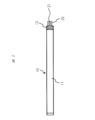
まず、添付の図1及び図2には、本発明になる線状光源装置を構成する線状の導光体10の正面図及び底面図が示されている。なお、この導光体10は、例えば、アクリル等の透光性の樹脂を金型成型により、導光体光放射面の曲面化の一例として、図示のように、弓状に湾曲して形成されている。そして、大略すれば、その外周面の一部又は全部から光を外部に向かって照射する発光部である動作部11と、後にも詳細を示す固体状光源、例えばLED光源部からの光を、例えば、その一部に形成した集光手段により略平行光に変換して上記動作部11へ導入するための光導入部12とを備えて構成されている。なお、本例の導光体10では、動作部11は、光導入部12に対して30度以上で90度以下の角度で屈曲して形成されている。
なお、本例では、導光体10を構成する動作部11及び光導入部12は、共に、方形断面を有するものとして示しているが、しかしながら、本発明はこれにのみ限定されるものではなく、その他、例えば、正方形や長方形を含む矩形、又は、円形や楕円の断面のものであってもよい。また、この動作部11の外周面には、例えば、動作部11の湾曲凸面部に位置する曲面14および動作部11の湾曲凹面部に位置する曲面15に以下にも詳細に述べるが、導光体10の内部を伝播する光を外部に照射するためのパターンが形成されている。
また、これらの図からも明らかなように、導光体10を構成する動作部11と光導入部12との間には、例えば、動作部11の湾曲凸面部側の面に楔状の切欠き部13が形成されており、そして、光導入部12の一部には、上記導光体10を確実に保持しながら所望の位置に固定するための固定部20が、アクリル等の透光性の高い樹脂により、金型で一体に形成されている。なお、図中、当該固定部20にはネジ溝21が形成されている。
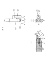
更に、図3(A)~(C)は、上記導光体10の光導入部12を拡大して示しており、これらの図からも明らかなように、この導光体10には、固定部20が一体に形成されている。即ち、光導入部12の端部には、図に破線で示すように、その略中心部には、円筒状の空間(LED収納部)121が形成されており、これにより、その内部に光源であるLED素子を格納すると共に、後にも詳述するが、当該LED光源からの光を内部に導入するための光導入面が形成されている。
また、上記光導入部12の端部では、その外周面(4面)が傾斜して形成されている。例えば、図の縦方向に対向する一対の面の傾斜角度αは、一例として、本例では、α=70度に設定されており、また、他の(図の横方向に対向する)一対の面は、複数の面の傾斜角度αを徐々に段階的に変化させることにより(例えば、β1=45度、β2=30度、β3=15度)、ほぼ湾曲面状にした面を形成している。なお、図示の光導入部12は、例えば、縦(H)=12mm、横(W)=6mmの、所謂、長方形状の断面を有している。
なお、図3(B)に示す断面には、上述した光導入部12の端部の略中心部に形成された円筒状の空間(LED収納部)121が示されており、図にも示すように、当該円筒形状は、底面の径φ1=2.2mm、開口面の径φ2=3.2mm、そして、高さh=1.5mmの円錐台形状に形成されている。また、上述した集光手段として、当該円錐台の上面である底面にレンズを形成し、これにより、LED光源部からの光を集光して略平行光に変換することも可能である。
あるいは、上述した構成に代え、上記光導入部12の端部は、図4(A)及び(B)にも示すように、連続的に変化する湾曲面としてもよい。なお、本例は、図のX軸(中心軸)に対し、以下の式で規定された同芯面としたものである。なお、ここでは、径φ1=2.2mm、φ2=1.6×2=3.2mmである。
R=1e-5X4+0.0011X3-0.0359X2+0.6437X+1.6…(式1)
更には、図5(A)及び(B)にも示すように、上述した長方形断面を有するものに替え、正方形の断面形状を有する光導入部12とし、その端部に上述した湾曲面を形成することも可能である。
即ち、上述した光導入部12の構成によれば、当該光導入部12の内部に伝播したLED光源からの光は、その端部において外部への漏洩を最小限として、透光体の内部で反射されることにより略平行光に変換されて集光され、光を外部へ照射する動作部11へ到ることとなる。
また、上述した固定部20は、同様に、アクリル等の透光性の樹脂により、上記導光体10と一体に金型で形成されているが、光の外部への漏洩をより低減するため、光学的に隔離されて形成されている。より詳細には、上記の図からも明らかなように、固定部20は、光導入部12と同様、正方形や長方形等を含む矩形状の断面を有し、光導入部12と平行して、即ち、その間に、光学的に隔離するための空間を挟んで形成されており、そして、その端部は、光導入部12において、上述した平行光に変換するための傾斜/湾曲面が形成された部位よりも動作部11側に近い位置において、上記光導入部12に連接するように、外形略「L」字状に形成されている。かかる固定部20の構成によれば、光導入部12においてLED光源部から内部に導入された光が当該固定部20を介して外部に漏洩することをより低減しながら、導光体10を含む上述した線状光源装置の全体を所定の位置に、確実に、固定/保持することが可能となる。
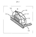
次に、図6は、上述のように導光体10の光導入部12の端部に形成された円錐台形状の空間であるLED収納部121に格納されるLED光源部100の一例を示す。図にも示すように、このLED光源部100は、青色の光を発光するLED素子101を樹脂102で封止して形成されたLED光源103を、基板104上に搭載して構成されている。なお、樹脂102の少なくとも一部(図示せず)には、LEDの青色発光色の一部を吸収し黄色の蛍光を発色する蛍光体が含有されている。また、樹脂102をさらに覆う部材として、LED素子101からの発光光および樹脂102に含まれる蛍光体から蛍光光の配光を制御する樹脂からなる半球ドーム105が形成されている。
続いて、上述した導光体10の動作部11における曲面14において、当該導光体10の内部を伝搬する光を外部に向かって照射するため、その外周面に形成された周期的な構造からなるパターン(模様)について、以下に詳細に説明する。
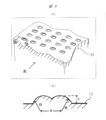
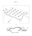
まず、図7(A)及び(B)には、球面連接の凹状のパターンの一例が示されている。即ち、この球面連接凹パターンは、2つの同一の半球状の凹部を連接して形成してなる(対称な)パターンを形成したものである。より具体的には、曲率R=0.1mmの同一の半球状の凹部を2個、図に矢印で示す光の入射方向(即ち、線形の動作部11の長手方向)に垂直な方向に並べ(両者間隔d=0.1mm)(図7(A)参照)、同じ深さ(=0.04mm)で連続した構造(図7(A)のB-B断面=図7(B)を参照)を、縦横方向において0.5mm×0.5mmのピッチで形成したものである。なお、曲面14に対向する曲面15上には、同様のパターンが形成される。ただし、パターンの曲率R=0.15mm、パターン両者間隔d=0.15mm、深さは同じ深さ(=0.04)、縦横方向において0.56mm×0.56mmのピッチで形成した。パターンのピッチが面14と異なる理由は、曲面14に形成されたパターンとの相互干渉によるモアレ発生を防止するためのものであり、縦横方向におけるピッチは、曲面14上に形成されたピッチに対して、少なくとも10%以上異なったピッチにする事が望ましい。
また、図8(A)及び(B)は、曲面14上に曲率R=0.1mmの半球状の凹部を2個、但し、図に矢印で示す光の入射方向に並べ(両者間隔d=0.1mm)(図8(A)参照)、かつ、互いに異なる深さdp(手前dp1=0.02mm、奥dp2=0.04mm)で連続した(非対称な)構造(図8(A)のB-B断面=図8(B)参照)を、縦横方向において、ピッチP=0.5mm×0.5mmで形成したものである。なお、凹形状のパターンを形成した場合、前記凹形状の深さdpは、手前側より奥側を深くした方が、深さを同一にした場合、あるいは、手前側を逆に深くした場合に比べ、導光体10の動作部11より放出される光において、前記LED光源の法線方向の強度が1割程度強くなり、配光特性が改善される事が実験により確認された。なお、曲面14に対向する曲面15上には、同様のパターンが形成される。ただし、パターンの曲率R=0.15mm、パターン両者間隔d=0.15mm、深さは同じ深さ(=0.04mm)、縦横方向において0.56mm×0.56mmのピッチで形成した。
なお、かかるパターンの形成は、特に、上述した金型による射出成形では、金型の表面に予め上記凹部に対応する凸部を形成することにより可能である。しかしながら、本発明では、このパターンは、上述した凹状のものに限定されるものではなく、これに代えて、凸状のパターンとしてもよく、その例を以下に説明する。
図9(A)及び(B)には曲面14上における球面連接の凸状のパターンの一例が示されており、この球面連接凸パターンでは、2つの同一の半球状の凸部を連接して形成してなる(対称な)パターンを形成したものである。より具体的には、曲率R=0.2mmの同一の半球状の凸部を2個、図に矢印で示す光の入射方向(即ち、線形の動作部11の長手方向)に垂直な方向に並べ(両者間隔d=0.2mm)(図9(A)参照)、同じ高さ(h=0.06mm)で連続した構造(図9(A)のB-B断面=図9(B)参照)を、縦横方向において、ピッチP=0.5mm×0.5mmで形成したものである。なお、曲面14に対向する曲面15上には、同様のパターンが形成される。ただし、パターンの曲率R=0.2mm、パターン両者間隔d=0.2mm、高さは同じ高さ(=0.06mm)、縦横方向において0.56mm×0.56mmのピッチで形成した。パターンのピッチが面14と異なる理由は、曲面14に形成されたパターンとの相互干渉によるモアレ発生を防止するためのものであり、縦横方向におけるピッチは、曲面14上に形成されたピッチに対して、少なくとも10%以上異なったピッチにする事が望ましい。
また、図10(A)及び(B)は、曲面15上に曲率R=0.2mmの半球状の凸部を2個、但し、図に矢印で示す光の入射方向に並べ(両者間隔d=0.2mm)(図10(A)参照)、かつ、互いに異なる高さ(手前h1=0.02mm、奥h2=0.04mm)で連続した(非対称な)構造(図10(A)のB-B断面=図10(B)参照)を、縦横方向において、ピッチP=0.5mm×0.5mmで形成したものである。なお、凸形状のパターンを形成した場合、前記凸形状の深さdpは、手前側より奥側を浅くした方が、深さ同一にした場合、あるいは、手前側を逆に深くした場合に比べ、導光体10の動作部11より放出される光において、前記LED光源の法線方向の強度が1割程度強くなり、配光特性が改善される事が実験により確認された。なお、曲面14に対向する曲面15上には、同様のパターンが形成される。ただし、前記と同様の理由により縦横方向において0.56mm×0.56mmのピッチで形成した。
なお、このような凸パターンの形成は、上述した凹パターンの形成と比較し、金型の表面に予め上記の凸部に代えて、例えば、ドリルによる円筒状の凹部を形成するだけでよいことから、製造コスト、特に、金型による製造にとってはより好適なパターンとなる。
また、上記の導光体10の動作部11において、その外周面に形成される周期的な構造からなるパターン(模様)は、上述した球面連接のパターンだけに限られず、例えば、その他の形状とすることも可能である。また、例えば、上記の球面連接の凹状パターン又は凸状パターンを動作部11の外周面に形成する際、これらを、適宜、組み合わせて形成することも可能である。
例えば、図8(A)、(B)及び図10(A)、(B)に示すような同じ半球状の凹部又は凸部を2つ連接したパターンを、動作部11の長手方向において、光の入射側、即ち、光導入部12に近い位置に形成し、図7(A)、(B)及び図9(A)、(B)に示すような異なる半球状の凹部又は凸部を2つ連接したパターンは、光導入部12から遠い位置に形成してもよい。また、図8(A)、(B)から図7(A)、(B)に示した形状、もしくは、図10(A)、(B)から図9(A)、(B)に示した形状に徐々に形状を変えても良い。形状の変化の仕方は、隣接パターン配置を動作部11の長手方向に沿った方向から徐々に回転させ、最終的に長手方向に対して直行させれば良い。これによれば、光導入部12に相対的に近いパターンは、導光体10の動作部11を伝搬する光に対して、相対的に回折強度が低く、光導入部12に対して遠い部分は相対的に回折強度が高くなる。一方、動作部11を伝搬する光強度自体は、光導入部12から遠い位置にかけ、徐々に弱くなるので、前記相対的な回折強度変化と相まって、パターンによる回折強度の絶対は、均一化される。本構成により、動作部11の長手方向において、その側面から放射される光強度の均一性及び配光特性の両立を確保でき、均一で充分に明るい光を照射することが可能となる。更には、動作部11の長手方向の光導入部12から距離に応じて、形成される凹部又は凸部の深さや高さを変えることによっても、同様の効果を得ることが可能である。また、パターン形状は、以上述べたように面内で変化させる事は可能であるが、周期的に形成された構造の導光体10の動作部表面の法線方向からみた投影断面積の比率の最小値Sminと最大値Smaxとの比率Smin/Smaxが略0.5以上(但し、1以下)とする事が望ましい。本構成を採用することにより、LED非発光時の外光による散乱光強度は、面内でほぼ均一強度となるので、LED非発光時にも、意匠性の優れた導光体を実現出来る。さらに、本構成を採用することにより、導光体10の動作部11からの発光強度の均一性及びLED非発光時の外光による散乱特性の均一性の両立が可能となる。
また、上記の導光体10の動作部11において、その外周面に形成された周期的な構造からなるパターン(模様)は、上述した球面連接のパターンだけに限られることなく、例えば、以下のような四角錐台形状のパターンとすることもできる。
図11(A)~(C)は、四角錐台形状の凹部を、その長手方向が図に矢印で示す光の入射方向に垂直になるように、かつ、縦横方向において0.3mm×0.3mmのピッチで形成したものである(図11(A)参照)。なお、この例では、一例として、四角錐台形状は、幅w=0.25mm、長さl=0.1mm、深さd=0.09mmであり、光入射側の側面の傾斜角θin=20度、出射側の側面の傾斜角θout=80度(図11(A)のB-B断面=図11(B)参照)、両側の側面の傾斜角θside=60度となっている(図11(A)のC-C断面=図11(C)参照)。
図12(A)~(C)は、四角錐台形状の凹部を、その長手方向が図に矢印で示す光の入射方向に沿うように、かつ、縦横方向において0.3mm×0.3mmのピッチで形成したものである(図12(A)参照)。なお、この例では、四角錐台形状は、幅w=0.1mm、長さl=0.25mm、深さd=0.05mmであり、光入射側の側面の傾斜角θin=20度、出射側の側面の傾斜角θout=80度、両側の側面の傾斜角θside=60度である。
なお、上述したパターンも、上記と同様、四角錐台形状の凸部として形成してもよく、更に、これらを、適宜、組み合わせ、更には、動作部11の長手方向の光導入部12から距離に応じて形成される凹部又は凸部の深さや高さを変えることによっても、同様の効果を得ることが可能である。
また、上記でも既に述べたが、上述した球面連接形状又は構造の四角錐台形状の凹部又は凸部は、当該構造の代表周期である、所謂、ピッチPを、0.6mm以下で形成することが好ましい。即ち、当該構造の代表周期を0.6mm以下とすることによれば、観察者が導光体10を見た場合、その間の距離が2m程度以上であれば、当該パターン周期の見かけの角度が1分(1/60度)以下となるので、通常の視力では、パターンの構造を個々に認識することは困難となるので、パターンの非視認性が確保でき、意匠性に優れた導光体10を実現できる。また、当該構造の代表周期である、所謂、ピッチPを、0.1mmより小さくすると、必要となる当該パターンの数が多くなり、加工工数が増えるばかりでなく、必要となる形状精度を実現するのが困難となり、パターンよる所望散乱光成分以外の成分が増加する。従って、当該構造の代表周期である、所謂、ピッチPを、0.1mm以上とする事が望ましい。
続いて、上記にその詳細な構造や動作を説明した本発明になる線状光源装置を製品に適用した例について、以下に詳細に説明する。
(実施例1)
図13(A)及び(B)は、上述した本発明になる線状光源装置を、天井に取り付ける照明器具である、所謂、シーリングライトに適用した例を示す。本例では、これらの図からも明らかなように、4本の線状光源装置が、天井(図示せず)の一部に取り付けられ、商用電源をLED駆動用電源に変換して供給する電源装置30の一部に、上記導光体10を構成する固定部20によって取り付けられて固定され、そして、その発光部である動作部11が、略90度の角度で均等に放射状に配置された照明器具を構成している。
図13(A)及び(B)は、上述した本発明になる線状光源装置を、天井に取り付ける照明器具である、所謂、シーリングライトに適用した例を示す。本例では、これらの図からも明らかなように、4本の線状光源装置が、天井(図示せず)の一部に取り付けられ、商用電源をLED駆動用電源に変換して供給する電源装置30の一部に、上記導光体10を構成する固定部20によって取り付けられて固定され、そして、その発光部である動作部11が、略90度の角度で均等に放射状に配置された照明器具を構成している。
また、図14は、同様に、本発明になる線状光源装置を天井に取り付けるシーリングライトに適用した例であって、6本の線状光源装置によって略60度の角度で均等に放射状に配置された照明器具を構成している。なお、これらの例では、図13に示すように各動作部11の裏側には、所謂、カバー部40が取り付けられており、そのため、この例では、光の発光部である動作部11の4面の外周にうち、当該カバー部40に対向する面およびカバー部40とは反対面に、上述した周期的な構造からなるパターン(模様)を形成することが好ましい。また、カバー部40の導光体10の動作部11と対向する面は、反射率が高い構造が望ましい。
(実施例2)
次に、図15(A)及び(B)は、上述した本発明になる線状光源装置を、自動車のヘッドライト部50において、DRL(Daytime Running Lamp)機能を有する車両用灯具51として適用した例を示す。本例では、これらの図からも明らかなように、ヘッドライト部50を構成するダウンライト52とアップライト53の上方において、本発明になる線状光源装置を水平方向に配置することによりDRLライトとしている。この例でも、上記と同様に、ヘッドライト部50を内部に収納する筺体(ケース)55の一部において、LED駆動用電源を供給する電源装置30の一部に、その固定部20によって取り付けられて固定されている。
次に、図15(A)及び(B)は、上述した本発明になる線状光源装置を、自動車のヘッドライト部50において、DRL(Daytime Running Lamp)機能を有する車両用灯具51として適用した例を示す。本例では、これらの図からも明らかなように、ヘッドライト部50を構成するダウンライト52とアップライト53の上方において、本発明になる線状光源装置を水平方向に配置することによりDRLライトとしている。この例でも、上記と同様に、ヘッドライト部50を内部に収納する筺体(ケース)55の一部において、LED駆動用電源を供給する電源装置30の一部に、その固定部20によって取り付けられて固定されている。
なお、この例でも、各動作部11の裏側には、所謂、反射板54が配置されていることから、上述した周期的な構造からなるパターン(模様)は、当該反射板54に対向する面を含め、およびその反対側の表面に形成することが好ましい。
以上にも詳細に述べたように、本発明の線状光源装置は、導光体10を他の構造体に固定するための固定部20を、その光源となるLED素子が配置される光導入部12の近傍に具備しているので、当該光導入部12とLED光源との相対位置を正確に固定することが可能となる。また、前記固定部20は、前記光導入部12からは光学的に隔離されているので、前記LED発光素子からの光の漏れを少なくして、光を外部に発光する線状の動作部11に導入する事が可能となることから、LED素子から射出される光を有効に活用でき、単一のLED素子でも、充分に明るい線状光源装置を実現できる。
また、発光する動作部11からの発光光を制御するために、その表面には周期的な構造が形成されており、かつ、当該構造の代表周期が0.6mm以下に設定されていることから、線状光源装置と観察者との距離を2m程度以上保つことにより、前記パターン周期の見かけの角度が1分(1/60度)以下となるので、通常の視力では、個々のパターン認識は困難となり、パターンの非視認性が確保でき、意匠性にも優れた線状光源装置を実現できる。
さらに、発光する動作部11の表面に周期的に形成された構造の少なくとも一部を、前記LED光の導入側と他端側で非対称な形状とすることにより、当該表面から放射される光強度の均一性及び配光特性の両立を確保することができる。また、動作部11と光導入部12を含む線状の導光体10は、屈曲部の凸部に切欠き部13を有する事により、当該光導入部12に対して動作部11が30度以上屈曲していても、動作部11の端部までの発光の均一性を確保できる。
また、動作部11の表面に周期的に形成された構造の少なくとも一部を、深さが異なる球面状くぼみの組み合わせとすること、あるいは、その高さが異なる球面状突起の組み合わせにすること、あるいは、前記LED光の導入側と他端側で傾斜角度が異なる四角錐台形状にすることによれば、前記LED光の導入側と他端側で非対称な形状を、低コストで容易に実現可能であり、導光体10の動作部11の表面から放射される光の強度の均一性及び配光特性の両立を、低コストで実現できる。
さらに、動作部11の表面に周期的に形成された構造の少なくとも一部を、LED光の導入側と他端側ではその形状が異なる形状とし、かつ、前記動作部11の表面には、周期的に形成された構造の導光体表面の法線方向からみた投影断面積の比率の最小値Sminと最大値Smaxとの比率Smin/Smaxが0.5以上(但し、1以下)とすることにより、導光体側面からの発光強度の均一性及びLED非発光時の外光による散乱特性の均一性の両立が可能となる。
なお、本発明は、上記した実施例にのみ限定されるものではなく、様々な変形例が含まれる。例えば、上記した実施例は本発明を分かりやすく説明するためにシステム全体を詳細に説明したものであり、必ずしも説明した全ての構成を備えるものに限定されるものではない。また、ある実施例の構成の一部を他の実施例の構成に置き換えることが可能であり、また、ある実施例の構成に他の実施例の構成を加えることも可能である。また、各実施例の構成の一部について、例えば、LED光源を半導体レーザ、面発光レーザ等の他の固体光源に置き換える等々、他の構成の追加・削除・置換をすることが可能である。
10…導光体、11…(発光)動作部、12…光導入部、20…固定部、21…ネジ溝、121…LED収納部、100…LED光源部、101…LED素子、102…樹脂、104…基板
Claims (12)
- 固体光源と、
前記固体光源からの出射光を受けてその一部から光を外部に照射する導光体とを備えた線状光源装置であって、
前記導光体は、透光性の樹脂を、所望の形状に形成してなる線状の動作部と、
前記動作部の一方の端部に一体に形成され、前記固体光源からの出射光を受光して略平行光に変換して当該略平行光を前記動作部へ導くための光導入部とを備えており、更に、
当該光導入部の一部には、前記線状光源装置を固定するための固定部が、当該光導入部と光学的に隔離されて、前記透光性の樹脂で一体に形成されていることを特徴とする線状光源装置。 - 前記請求項1に記載した線状光源装置において、
前記光導入部には、前記動作部が一体に形成された端部とは反対側の端部において、前記固体光源を収納する空間部と共に、当該固体光源からの出射光を受光する受光面が形成されており、かつ、当該端部の外周面には、前記受光面で受光した光を略平行光に変換するための変換面を形成しており、
前記固定部は、前記光導入部に対して空間を挟んで平行に形成されており、その一端部を、前記光導入部の外周面の前記変換面を除いた一部に連接して、一体に形成されていることを特徴とする線状光源装置。 - 前記請求項2に記載した線状光源装置において、
前記固定部は、その一端部を、前記光導入部の外周面の、前記変換面よりも前記動作部側に隣接した一部に連接して、一体に形成されていることを特徴とする線状光源装置。 - 前記請求項1~3の何れか1項に記載した線状光源装置において、
前記導光体を構成する前記線状の動作部の外周表面の一部には、周期的な構造からなるパターンが形成されており、前記パターンを構成する前記構造の代表周期が0.1mm以上かつ0.6mm以下あることを特徴とする線状光源装置。 - 前記請求項4に記載した線状光源装置において、
前記線状の動作部の外周表面に周期的に形成された構造の少なくとも一部は、光の導入側とその他端側では、非対称な形状を呈していることを特徴とする線状光源装置。 - 前記請求項4に記載した線状光源装置において、
前記線状の導光体を構成する前記動作部の端部は、前記光導入部に対して、30度以上で90度以下の角度で屈曲しており、かつ、当該屈曲部に隣接して前記屈曲部の凸側面に切欠きを有していることを特徴とする線状光源装置。 - 前記請求項4に記載した線状光源装置において、
前記動作部の表面に周期的に形成された構造の少なくとも一部は、深さが異なる球面状くぼみの組み合わせであることを特徴とする線状光源装置。 - 前記請求項4に記載した線状光源装置において、
前記動作部の表面に周期的に形成された構造の少なくとも一部は、高さが異なる球面状突起の組み合わせであることを特徴とする線状光源装置。 - 前記請求項4に記載した線状光源装置において、
前記動作部の表面に周期的に形成された構造の少なくとも一部は、光の導入側と他端側では角度が異なる四角錐台形状であることを特徴とする線状光源装置。 - 前記請求項4に記載した線状光源装置において、
前記動作部の表面に周期的に形成された構造の導光体表面の法線方向からみた投影断面積の比率の最小値Sminと最大値Smaxとの比率Smin/Smaxが0.5以上で1以下であることを特徴とする線状光源装置。 - 天井面に取り付ける照明器具であって、
前記請求項1~10の何れか1項に記載した線状光源装置を光源として備えていることを特徴とする照明器具。 - 自動車の正面に取り付ける車両用灯具であって、
前記請求項1~10の何れか1項に記載した線状光源装置を光源として備えていることを特徴とする車両用灯具。
Priority Applications (1)
| Application Number | Priority Date | Filing Date | Title |
|---|---|---|---|
| PCT/JP2014/070506 WO2016020974A1 (ja) | 2014-08-04 | 2014-08-04 | 線状光源装置及びそれを利用した照明器具と車両用灯具 |
Applications Claiming Priority (1)
| Application Number | Priority Date | Filing Date | Title |
|---|---|---|---|
| PCT/JP2014/070506 WO2016020974A1 (ja) | 2014-08-04 | 2014-08-04 | 線状光源装置及びそれを利用した照明器具と車両用灯具 |
Publications (1)
| Publication Number | Publication Date |
|---|---|
| WO2016020974A1 true WO2016020974A1 (ja) | 2016-02-11 |
Family
ID=55263280
Family Applications (1)
| Application Number | Title | Priority Date | Filing Date |
|---|---|---|---|
| PCT/JP2014/070506 Ceased WO2016020974A1 (ja) | 2014-08-04 | 2014-08-04 | 線状光源装置及びそれを利用した照明器具と車両用灯具 |
Country Status (1)
| Country | Link |
|---|---|
| WO (1) | WO2016020974A1 (ja) |
Cited By (2)
| Publication number | Priority date | Publication date | Assignee | Title |
|---|---|---|---|---|
| CN106369549A (zh) * | 2016-09-30 | 2017-02-01 | 马瑞利汽车零部件(芜湖)有限公司 | 发光均匀且尾部无光斑的车灯光导 |
| CN106646719A (zh) * | 2016-10-28 | 2017-05-10 | 马瑞利汽车零部件(芜湖)有限公司 | 一种汽车灯光导光条 |
Citations (6)
| Publication number | Priority date | Publication date | Assignee | Title |
|---|---|---|---|---|
| JP2000067624A (ja) * | 1998-08-13 | 2000-03-03 | Mitsubishi Chemicals Corp | 面光源装置 |
| JP2002214444A (ja) * | 2001-01-17 | 2002-07-31 | Nippon Columbia Co Ltd | 導光板および液晶表示装置 |
| JP2010020920A (ja) * | 2008-07-08 | 2010-01-28 | Sharp Corp | 線状光源装置および画像読取装置 |
| JP2014022309A (ja) * | 2012-07-23 | 2014-02-03 | Toshiba Elevator Co Ltd | 照明装置 |
| JP2014067688A (ja) * | 2012-09-04 | 2014-04-17 | Sharp Corp | 光源モジュール、照明モジュール及び照明機器 |
| JP2014093193A (ja) * | 2012-11-02 | 2014-05-19 | Toppan Printing Co Ltd | 導光板、導光板を備えたバックライトユニットおよびディスプレイ装置 |
-
2014
- 2014-08-04 WO PCT/JP2014/070506 patent/WO2016020974A1/ja not_active Ceased
Patent Citations (6)
| Publication number | Priority date | Publication date | Assignee | Title |
|---|---|---|---|---|
| JP2000067624A (ja) * | 1998-08-13 | 2000-03-03 | Mitsubishi Chemicals Corp | 面光源装置 |
| JP2002214444A (ja) * | 2001-01-17 | 2002-07-31 | Nippon Columbia Co Ltd | 導光板および液晶表示装置 |
| JP2010020920A (ja) * | 2008-07-08 | 2010-01-28 | Sharp Corp | 線状光源装置および画像読取装置 |
| JP2014022309A (ja) * | 2012-07-23 | 2014-02-03 | Toshiba Elevator Co Ltd | 照明装置 |
| JP2014067688A (ja) * | 2012-09-04 | 2014-04-17 | Sharp Corp | 光源モジュール、照明モジュール及び照明機器 |
| JP2014093193A (ja) * | 2012-11-02 | 2014-05-19 | Toppan Printing Co Ltd | 導光板、導光板を備えたバックライトユニットおよびディスプレイ装置 |
Cited By (2)
| Publication number | Priority date | Publication date | Assignee | Title |
|---|---|---|---|---|
| CN106369549A (zh) * | 2016-09-30 | 2017-02-01 | 马瑞利汽车零部件(芜湖)有限公司 | 发光均匀且尾部无光斑的车灯光导 |
| CN106646719A (zh) * | 2016-10-28 | 2017-05-10 | 马瑞利汽车零部件(芜湖)有限公司 | 一种汽车灯光导光条 |
Similar Documents
| Publication | Publication Date | Title |
|---|---|---|
| JP3169376U (ja) | 発光ダイオード式照明装置 | |
| US20190120448A1 (en) | Downlight apparatus | |
| WO2014080771A1 (ja) | 照明装置 | |
| CN111207360B (zh) | 车辆用灯具 | |
| EP2811217B1 (en) | Illumination apparatus | |
| JP2015076249A (ja) | 車両用灯具 | |
| JP6304538B2 (ja) | 照明器具 | |
| JP6241601B2 (ja) | 照明装置 | |
| WO2016020974A1 (ja) | 線状光源装置及びそれを利用した照明器具と車両用灯具 | |
| JP5022118B2 (ja) | 面状発光装置 | |
| KR101094251B1 (ko) | 전방위로 조사되는 led 모듈 | |
| CN108692292A (zh) | 透镜以及照明器具 | |
| JP5322292B2 (ja) | Ledユニットおよび照明器具 | |
| JP5707563B2 (ja) | 照明器具 | |
| JP5489338B2 (ja) | 照明器具 | |
| KR20160089070A (ko) | 엘이디 조명등 | |
| JP6429672B2 (ja) | 発光装置及びこれを用いた照明器具 | |
| CN107667248B (zh) | 管状发光设备 | |
| KR101491114B1 (ko) | Led램프 | |
| JP2014211996A (ja) | 照明装置 | |
| JP6227720B2 (ja) | 照明器具 | |
| JP6345539B2 (ja) | 光束制御部材および発光装置 | |
| JP6199246B2 (ja) | 照明器具 | |
| JP5595065B2 (ja) | 照明器具 | |
| JP6179766B2 (ja) | 照明器具 |
Legal Events
| Date | Code | Title | Description |
|---|---|---|---|
| 121 | Ep: the epo has been informed by wipo that ep was designated in this application |
Ref document number: 14899151 Country of ref document: EP Kind code of ref document: A1 |
|
| NENP | Non-entry into the national phase |
Ref country code: DE |
|
| NENP | Non-entry into the national phase |
Ref country code: JP |
|
| 122 | Ep: pct application non-entry in european phase |
Ref document number: 14899151 Country of ref document: EP Kind code of ref document: A1 |