WO2016017489A1 - 三次元測定装置 - Google Patents
三次元測定装置 Download PDFInfo
- Publication number
- WO2016017489A1 WO2016017489A1 PCT/JP2015/070782 JP2015070782W WO2016017489A1 WO 2016017489 A1 WO2016017489 A1 WO 2016017489A1 JP 2015070782 W JP2015070782 W JP 2015070782W WO 2016017489 A1 WO2016017489 A1 WO 2016017489A1
- Authority
- WO
- WIPO (PCT)
- Prior art keywords
- image
- reference spot
- spot image
- measured
- pattern
- Prior art date
- Legal status (The legal status is an assumption and is not a legal conclusion. Google has not performed a legal analysis and makes no representation as to the accuracy of the status listed.)
- Ceased
Links
Images



Classifications
-
- G—PHYSICS
- G01—MEASURING; TESTING
- G01B—MEASURING LENGTH, THICKNESS OR SIMILAR LINEAR DIMENSIONS; MEASURING ANGLES; MEASURING AREAS; MEASURING IRREGULARITIES OF SURFACES OR CONTOURS
- G01B11/00—Measuring arrangements characterised by the use of optical techniques
- G01B11/24—Measuring arrangements characterised by the use of optical techniques for measuring contours or curvatures
- G01B11/25—Measuring arrangements characterised by the use of optical techniques for measuring contours or curvatures by projecting a pattern, e.g. one or more lines, moiré fringes on the object
Definitions
- the present invention relates to a three-dimensional measuring apparatus that generates a plurality of reference spots on a reference plane and acquires the reference spots by an imaging unit, thereby detecting a measured object that appears in front of the reference plane.
- Patent Document 1 describes an invention relating to a three-dimensional measuring apparatus that detects a measurement object using a coherent light source.
- a random speckle pattern generated from a coherent light source is irradiated to an illumination area, and an optical response from the illumination area is detected by an imaging unit. Detects speckle pattern deviation between the pattern image obtained when the measured object moves to the illumination area and the reference image of the random speckle pattern when the measured object does not exist. This is used to construct a three-dimensional map of the object to be measured.
- the present invention solves the above-described conventional problems, and an object of the present invention is to provide a three-dimensional measuring apparatus that can accurately detect an object to be measured and that can reduce the burden on a CPU and the like with a relatively small amount of calculation.
- the present invention is provided with a light irradiation member that irradiates a reference surface with coherent light to form a plurality of reference spots, an imaging member that acquires a reference spot image, and a determination unit.
- a plurality of reference spots are regularly arranged on the reference pattern, and the object to be measured is located on the reference pattern when the object to be measured is located between the light irradiation unit and the reference surface.
- the reference spot moves to the surface of the measured object,
- the determination unit determines that the moved reference spot image has moved from the shortest of the plurality of reference spot images located on the standard pattern. Thus, the presence of the object to be measured is discriminated.
- the three-dimensional measuring apparatus of the present invention uses a plurality of regularly arranged reference spots, and when the position of any of the reference spot images changes on the image, the three-dimensional measuring apparatus exists closest to the reference pattern. It is determined that the reference spot image is the movement source. In this determination, the object to be measured can be detected with a small amount of calculation.
- the distance that the reference spot image moves between two consecutive frames of the image is the same as the reference spot image after the movement.
- the imaging conditions are determined such that the distance is shorter than the distance from other reference spot images on the reference pattern.
- the imaging conditions include the focal length (f) of the imaging member, the base line length (B) between the light irradiating member and the imaging member, the frame rate ( ⁇ ), and the shortest pitch of the reference spot image in the standard pattern ( d) as well as the size or amount of movement of the object to be measured in a direction perpendicular to the reference plane.
- Equation 10 For example, it is possible to obtain at least one of the shape and dimensions of the object to be measured by using Equation 10 described later, and to obtain the movement amount of the object to be measured by using Equation 11 described later. it can.
- each reference spot is located on an irradiation line extending from the light irradiation member, and an imaging direction by the imaging member is opposed to each irradiation line with a predetermined angle.
- the reference spot image appearing on the image when the reference spot located in the reference pattern moves to the surface of the object to be measured can be configured to move on the epipolar line corresponding to the irradiation line.
- a plurality of reference spots are arranged at a constant pitch in both the row direction and the column direction orthogonal to each other, and the epipolar line is in both the row direction and the column direction. It is preferable that the arrangement direction of the reference spots in the standard pattern is determined so as to form a predetermined angle.
- the pitch of the reference spot images adjacent in the direction along the epipolar line can be secured long, and the movement amount of the reference spot image Even if is relatively long, it is easy to determine from which position in the reference pattern the movement has been made.
- the reference spots are arranged in a regular pattern in the standard pattern, and when the object to be measured exists and the reference spot image moves on the image, the reference spot after the movement is the standard. It is determined that the pattern has moved from the reference spot image existing at the shortest distance in the pattern. As a result, the object to be measured can be detected with high accuracy by a calculation process with relatively little burden.
- the present invention can determine the shape and size of the object to be measured by grasping which of the plurality of reference spot images has moved on the image. Further, by grasping which of the plurality of reference spot images has moved on the image, the movement of the measured object can be determined.
- 1 and 2 includes a reference surface 2, a light irradiation member 10 and an imaging member 20 facing the reference surface 2.
- the reference surface 2 shown in FIGS. 1 and 2 is a flat surface, but the reference surface 2 may be uneven.
- the XY plane is a plane parallel to the reference plane 2
- the XZ plane is a plane perpendicular to the reference plane 1.
- the light irradiation member 10 includes a laser light source 11 that is a coherent light source, a collimator lens 12 that converts a divergent light beam 14a emitted from the laser light source into a parallel light beam 14b, and a transmission type through which the parallel light beam 14b converted by the collimator lens 12 passes.
- Hologram element 13 The laser light source 11 emits laser light in the near infrared wavelength region that cannot be seen by humans. Alternatively, visible laser light may be emitted.
- the hologram element 13 is a phase type diffraction grating, the parallel light beam 14b is diffracted to form an irradiation light beam 14c having a predetermined divergence angle, and the irradiation light beam 14c is given to the reference surface 2.
- a plurality of reference reference spots 31 are projected on the reference plane 2.
- the plurality of reference reference spots 31 are formed by diffracting the laser beam by the hologram element 13.
- the reference reference spot 31 having a small round shape is formed on the reference surface 2.
- the shape of the reference reference spot 31 is not limited to a small circle, and an arbitrary shape can be selected.
- the standard reference spots 31 formed on the standard surface 2 which is a plane are arranged according to a regular projection pattern, and the standard pattern 30 is formed.
- regular means that when any one of the reference reference spots 31 is focused, the relative relationship between the direction and the distance between the reference reference spot 31 and the reference reference spot 31 adjacent in each direction is as follows. This means a relationship that is the same in all other reference reference spots 31.
- the standard reference spots 31 are arranged in a square lattice pattern arranged at a constant pitch in the row direction and the column direction.
- the reference reference spot 31 is irradiated with the row direction and the column direction inclined with respect to the XY direction.
- FIG. 2 shows an irradiation reference line Oa of the irradiation light beam 14c irradiated from the light irradiation member 10 toward the reference plane 2.
- the irradiation reference line Oa coincides with the optical axes of the laser light source 11, the collimating lens 12 and the hologram element 13.
- the irradiation reference line Oa is located in a plane parallel to the XZ plane, and the irradiation reference line Oa is less than 90 degrees with respect to the vertical line H from the reference plane 2 as shown in the plan view of FIG. They are arranged with an angle ⁇ .
- each irradiation line 15 has a diffusion angle because the irradiation light beam 14c is divergent light.
- FIG. 5 by ensuring a sufficiently long distance between the light irradiation member 10 and the reference surface 2, FIG. As shown in FIG. 5, the irradiation lines 15 can be expressed as an arrangement relationship substantially parallel to each other.
- FIG. 1 shows a state in which the object to be measured 5 has entered between the light irradiation member 10 and the reference surface 2.
- the measured object 5 is a human hand.
- a reference spot is projected on the surface.
- the reference spot projected on the surface of the object to be measured 5 is called a moving reference spot 32.
- the moving reference spot 32 is generated at the intersection of each irradiation line 15 and the surface of the measured object 5.
- the imaging member 20 has a video camera 21.
- FIG. 2 shows the imaging reference line Ob of the video camera 21.
- the imaging reference line Ob is the center line of the imaging field of view of the video camera 21, and coincides with the optical axis of the camera lens.
- the imaging reference line Ob is located in a plane parallel to the XZ plane, and the imaging reference line Ob is arranged in parallel with the vertical line H in this plane.
- the irradiation reference line Oa and the imaging reference line Ob face each other with an angle ⁇ in a plane parallel to the XZ plane.
- the angle ⁇ is an acute angle.
- the irradiation reference line Oa may be parallel to the vertical line H, or both the irradiation reference line Oa and the imaging reference line Ob are not parallel to the vertical line H. Also good. Further, the angle ⁇ is not limited to an acute angle.
- FIG. 3 shows an image 21 a captured by the video camera 21.
- a standard reference spot image 31a and a moving reference spot image 32a are projected.
- the reference reference spot image 31a and the moving reference spot image 32a mean an image obtained from the reflected light of the reference reference spot 31 and an image obtained from the reflected light from the moving reference spot 32.
- the moving reference spot image 32a extends from the reference reference spot image 31a.
- the epipolar line E is a virtual straight line connecting the standard reference spot image 31a and the moving reference spot image 32a to which the standard reference spot image 31a has moved in the image 21a.
- the image acquired by the video camera 21 is accumulated in the frame memory 22 for each frame (frame).
- a plurality of frames of images are stored in the frame memory 22, and when a new frame image is input, the oldest frame image is discarded.
- the image 21 a stored in the frame memory 22 is sent to the image analysis unit 23 for each frame, the image is analyzed, and the analysis result is sent to the determination unit 24.
- the measuring operation of the three-dimensional measuring apparatus 1 will be described.
- an image is acquired by the video camera 21 in a state where the reference reference spot 31 is projected on the reference plane 2.
- the image is accumulated in the frame memory 22 for each frame, and the image analysis unit 23 analyzes which reference spot has moved by comparing the images of the previous and subsequent frames.
- FIG. 5 illustrates an image 21a acquired for each frame.
- a horizontal axis u and a vertical axis v that are orthogonal to each other are added.
- the horizontal axis u corresponds to the X axis on the reference plane 2 shown in FIG. 4, and the vertical axis v corresponds to the Y axis on the reference plane 2.
- the epipolar line E on which the reference spot moves in the image 21a is determined by the opposed state of the irradiation reference line Oa and the imaging reference line Ob, and is not necessarily parallel to the horizontal axis u or the vertical axis v.
- the epipolar line E to which the reference spot moves is set to be parallel to the horizontal axis u (X axis) for the sake of explanation.
- FIG. 5 shows a standard reference spot image 31a that is a reflection image of the standard reference spot 31 shown in FIG.
- a plurality of reference reference spot images 31a are regularly arranged in a square lattice pattern. 30a.
- the moving reference spot image 32a appears in the image 21a if the measured object 5 exists and the moving reference spot 32 is irradiated on the surface thereof. .
- This moving reference spot 32a is located on the epipolar line E passing through the original standard reference spot image 31a.
- the moving reference spot image 32a appearing in the image 21a of the second frame is indicated by a small circle painted in black.
- the moving reference spot image 32a is the original of the moving reference spot image 32a. It moves on the epipolar line E passing through the position.
- the reference reference spot 31a regularly arranged in the first frame image 21a does not move, and the moving reference spot appears in the next second frame image 21a.
- the moving distance L1 on the epipolar line E between the reference reference spot image 31a of the first frame and the moving reference spot image 32a to be measured in the second frame is the first frame.
- the reference reference spot image 31a that is not the movement source among the plurality of reference reference spot images 31a that have already been acquired in step S3 is shorter than the shortest distance L2 between the reference reference spot image 31a that is the measurement target and the movement reference spot image 32a that is the measurement target (L1 ⁇ L2
- the imaging conditions are determined.
- the movement distance L1 on the epipolar line E of the moving reference spot image 32a that is the measurement target moved between the frames is determined as follows.
- the moving reference spot image 32a that is not the moving source and the moving reference spot image 32a to be measured are shorter than the shortest distance L2 (L1 ⁇ L2).
- L1 ⁇ L2 Like
- the conditions (L1 ⁇ L2) include the focal length (f) of the imaging member 20, the baseline length (B) between the light irradiation member 10 and the imaging member 10, the frame rate ( ⁇ ), and the shortest pitch (d ) As well as the size or amount of movement of the measured object 5 in the direction perpendicular to the reference plane 2.
- the object to be measured 5 is usually a human hand, and its size and moving speed, and the operation position in the Z direction with respect to the reference plane 2 can be predicted in advance.
- the condition (L1 ⁇ L2) when the measured object 5 exists in front of the reference plane 2 and the moving reference spot image 32a appears, the image 21a obtained in the immediately preceding frame is displayed.
- the reference reference spot image 31a located closest to the moving reference spot image 32a can be specified as the movement source of the moving reference spot image 32a.
- the movement reference spot image 32a located closest to the target movement reference spot image 32a can be specified as the movement source of the movement reference spot image 32a.
- identification symbols are given in advance so that they can be distinguished from each other.
- This identification code is a number representing a coordinate point. Since the coordinate point of the moving reference spot image 32a changes when it moves, the identification code changes, and the identification code of the corresponding moving reference spot image 32a differs between frames. However, in the discriminating unit 24, the identification symbol of the reference reference spot image 31a or the moving reference spot image 32a existing at the closest distance from the moved moving reference spot image 32a is that of the moved reference spot image 32a. It becomes possible to specify.
- the unit 24 can discriminate.
- This identification method can reduce the arithmetic processing compared to the conventional example using the reference spots arranged at random. Furthermore, even if the epipolar line E cannot be identified on the image, the reference reference spot image 31a as the movement source can be identified, so that the arithmetic processing for measuring the position and movement of the measured object 5 can be easily performed.
- the epipolar line E corresponding to the irradiation line 15 extends in the u-axis direction, but the row direction and the column direction of the reference pattern image 30a are parallel to the u-axis and the v-axis. is not. That is, the epipolar line E extends at an angle in the row direction and the column direction.
- the condition (L1 ⁇ L2) can be set more easily.
- FIG. 6A shows an example in which the epipolar line E matches the row direction of the reference pattern image 30a.
- FIG. 6B shows that the epipolar line E is 45 in the row direction and the column direction. An example extending at an angle of degrees is shown.
- the acquisition time of the previous and subsequent frames must be set so that the distance between the reference reference spot image 31a and the moving reference spot image 32a obtained in the next frame does not exceed (d / 2).
- the reference reference spot image 31a from which the moving reference spot image 32a has moved cannot be understood.
- (D) is the arrangement pitch of the standard reference spot images 31a.
- the moving reference spot image 32a by setting the direction of the epipolar line E to an angle of 45 ° ⁇ ⁇ ( ⁇ is less than 45 °) with respect to the row direction and the column direction, even if the frame rate is low, the moving reference spot image 32a.
- the reference reference spot image 31a having the shortest distance can be specified as the movement source.
- the moving reference spot image 32a when the moving reference spot image 32a appears or when the moving reference spot image 32a moves, the moving reference spot image 32a is centered on the reference reference spot image 31a that is the movement source. If the frame rate and other imaging conditions are set so as to be located inside the quadrangular area 35 having a side length of (d), the reference reference spot image located at the shortest distance from the moving reference spot image 32a. It is possible to specify 31a as the movement source.
- the standard reference spot images 31a are arranged in a square lattice pattern on the standard pattern image 30a, and the pitch of the standard reference spot images 31a in the row direction and the column direction is d.
- the direction of the epipolar line E is parallel to the u axis, and the angle formed by the epipolar line E and the row direction is ⁇ .
- ⁇ is ⁇ ( ⁇ / 4) ⁇ ⁇ ( ⁇ / 4).
- the uv coordinates are image coordinates, and Z is the Z component of world coordinates (spatial coordinates). That is, uv and Z are separate coordinate systems.
- f is a focal length of the video camera 21
- B is a baseline length between the light irradiation member 10 and the imaging member 20.
- the distances L1 and L2 shown in FIG. 5 can be defined by the following formula 4 and further organized by the formula 5.
- the focal length (f), the base line length (B), the arrangement pitch (d) and the angle ( ⁇ ) of the standard pattern 30a, and the shortest movement distance (Z min ) in the Z direction of the standard reference spot image 31a are adjusted.
- the condition (L1 ⁇ L2) can be realized.
- Equation 10 When the object to be measured 5 is already in the irradiation area of the reference pattern 30 and the object to be measured 5 moves between frames, the object to be measured 5 moves in the Z direction instead of ⁇ Z ⁇ (t k ).
- ⁇ is a frame rate
- ⁇ t 1 / ⁇ .
- the operation speed of the operation target that can realize the condition (L1 ⁇ L2).
- the condition (L1 ⁇ L2) in Equation 11 the amount of movement of the DUT 5 can be grasped.
- the distance L1 between the standard reference spot image 31a and the moving reference spot image 32a is calculated, and the standard reference spot 31a and the moving reference spot image 32a that existed at the closest distance are associated with each other.
- the distance calculation method may be changed instead of calculating the distance by comparing the coordinates of the reference reference spot image 31a and the moving reference spot image 32a. Specifically, the comparison may be performed after coordinate conversion of each spot image.
- the imaging member 20 can be considered as a stereo system with the imaging member 20 by regarding the spot image irradiated from the light irradiation member 10 as one image.
- a projective transformation matrix that represents the transformation between the spot image emitted from the light irradiating member 10 and the spot image in the imaging member 20 can be defined. Therefore, the projective transformation is performed to align the spot images. After that, the distance can be calculated.
- the projective transformation matrix means a transformation matrix of points between stereo images. Since the laser camera system can also be considered as a stereo system by regarding the laser projection pattern as one image, a projective transformation matrix representing the transformation between the projection pattern and the laser points in the camera image is defined. be able to.
- the projection transformation matrix obtained in the previous frame is used for the spot images in both the previous and subsequent frames.
- the projective transformation is either performed once for the entire image including all the spot images, or the image is divided, the projection transformation matrix is performed on each of the divided areas, and the result is combined. Just do it.
- the degree of freedom of the projective transformation matrix H is 8, and if there are a set of four or more virtual images and lattice points on the camera image, H can be obtained by the least square method.
- Equation 14 indicates the arrangement.
- Equation 16 If defined as Equation 15, h can be obtained as Equation 16 when ⁇ ⁇ 4.
- W + represents a pseudo inverse matrix of W.
- the method using this projective transformation matrix can be similarly calculated even when the object to be measured is already in the laser irradiation range and the object to be measured moves between frames.
Landscapes
- Engineering & Computer Science (AREA)
- Computer Vision & Pattern Recognition (AREA)
- Physics & Mathematics (AREA)
- General Physics & Mathematics (AREA)
- Length Measuring Devices By Optical Means (AREA)
Abstract
[課題]基準面に参照スポットを形成し撮像部材で取得した画像の参照スポットの移動状態を見て被測定物の存在を測定する三次元測定装置を提供する。 [解決手段]コヒーレント光により基準面(21a)に基準参照スポット像(31a)が正方格子状に規則的に並んだ基準パターン(30a)が成形される。基準面(21a)に測定対象物が現れその表面に参照スポットが形成されると、画像(21a)においては、基準参照スポット像(31a)がエピポーラ線(E)上を移動して移動参照スポット像(32a)となる。画像(21a)を取得する第1フレームからその次の第2フレームにかけて基準参照スポット像(31a)が移動参照スポット像(32a)に移動するまでの移動距離(L1)が、移動参照スポット像(32a)と他の基準参照スポ ット像(31a)との距離(L2)よりも短くなるように撮像条件を設定する。
Description
本発明は、基準面に複数の参照スポットを生成し、この参照スポットを撮像手段で取得することで、基準面の手前に現れる被測定物体を検知する三次元測定装置に関する。
特許文献1に、コヒーレント光源を使用して被測定物体を検知する三次元測定装置に関する発明が記載されている。
特許文献1に記載された三次元測定装置は、コヒーレント光源から生成されたランダムスペックルパターンが照明領域に照射され、照明領域からの光応答が画像化ユニットで検知される。被測定物体が照明領域に移動したときに得られるパターン画像と、被測定物体が存在していないときのランダムスペックルパターンの参照画像とでスペックルパターンのずれを検出し、三次元測量法を利用して、被測定物体の三次元マップを構築する、というものである。
特許文献1に記載された三次元測定装置は、スペックルパターンがランダムに形成され、被測定物体が存在してスペックルパターンがずれたときは、参照画像で設定されていたランダムパターンの特徴の相対ずれを検出するものとなっている。
この方法は、ランダムに配置された多数のスペックルパターンの相対位置関係を予め把握し、それぞれのスペックルパターンがどのように位置ずれしたかを相関アルゴリズムを使用して演算することが必要である。そのため、演算量が多くなり、CPUの負担が増大し、応答速度を速くするのに限界がある。
本発明は上記従来の課題を解決するものであり、被測定物体を精度良く検知でき、しかも演算量が比較的少なくCPUなどの負担を軽減できる三次元測定装置を提供することを目的としている。
本発明は、コヒーレント光を基準面に照射して複数の参照スポットを形成する光照射部材と、参照スポット像を取得する撮像部材と、判別部とが設けられており、
前記基準面では、複数の参照スポットが基準パターン上で規則的に配列し、被測定物体が前記光照射部と前記基準面との間に位置したときに、前記基準パターン上に位置していた参照スポットが、被測定物体の表面に移動し、
前記判別部では、前記画像上で参照スポット像が移動したら、移動後の参照スポット像が、基準パターン上に位置していた複数の参照スポット像のうちの最も距離が短いものから移動したと判定し、これにより被測定物体の存在が判別されることを特徴とするものである。
前記基準面では、複数の参照スポットが基準パターン上で規則的に配列し、被測定物体が前記光照射部と前記基準面との間に位置したときに、前記基準パターン上に位置していた参照スポットが、被測定物体の表面に移動し、
前記判別部では、前記画像上で参照スポット像が移動したら、移動後の参照スポット像が、基準パターン上に位置していた複数の参照スポット像のうちの最も距離が短いものから移動したと判定し、これにより被測定物体の存在が判別されることを特徴とするものである。
本発明の三次元測定装置は、規則的に配列する複数の参照スポットを使用し、画像上でいずれかの参照スポット像の位置に変化が生じたときに、基準パターンにおいて最も近くに存在していた参照スポット像が移動元であると判定する。この判定では、少ない演算量で被測定物体を検知することができる。
本発明の三次元測定装置は、参照スポットが被測定物の表面に移動する際に、前記画像の連続する2つのフレームの間で参照スポット像が移動する距離は、移動後の参照スポット像と基準パターン上の他の参照スポット像との距離よりも短くなるように、撮像条件が決められているものである。
例えば、前記撮像条件は、前記撮像部材の焦点距離(f)、前記光照射部材と前記撮像部材との基線長(B)、フレームレート(ν)、基準パターンでの参照スポット像の最短ピッチ(d)、ならびに前記基準面から垂直な方向での被測定物体の寸法または移動量、に基づいて決められる。
例えば、後に説明する数10を使用することで、被測定物の形状と寸法の少なくとも一方を求めることができ、後に説明する数11を使用することで、被測定物の移動量を求めることができる。
本発明の三次元測定装置では、それぞれの参照スポットは、前記光照射部材から延びる照射線上に位置し、前記撮像部材による撮像方向が、それぞれの前記照射線と所定角を有して対向しており、前記基準パターンに位置していた参照スポットが被測定物体の表面に移動したときに、画像上に現れる参照スポット像が、前記照射線に対応するエピポーラ線上を移動するものとして構成できる。
この場合に、前記基準パターンでは、複数の参照スポットが、互いに直交する行方向と列方向の双方に一定のピッチで配列しており、前記エピポーラ線は前記行方向と前記列方向の双方に対して所定の角度を成すように、基準パターンでの参照スポットの配列方向が決められていることが好ましい。
上記のように、エピポーラ線を行方向と列方向に対して所定の角度を成す向きに設定すると、エピポーラ線に沿う方向で隣り合う参照スポット像のピッチを長く確保でき、参照スポット像の移動量が比較的長くても、基準パターンのどの位置から移動してきたかを判別しやすくなる。
本発明は、基準パターンにおいて参照スポットが規則的な配列となるように配置されており、被測定対象物が存在して画像上で参照スポット像が移動したときに、移動後の参照スポットが基準パターンにおいて最短距離の位置に存在していた参照スポット像から移動したものと判断する。これにより、比較的負担の少ない演算処理で、被測定物体を高精度に検知することができる。
本発明は、画像上で、複数の参照スポット像のどれが移動したかを把握することで、被測定物体の形状と寸法を判別できる。また、画像上で、複数の参照スポット像のどれが移動したかを把握することで、被測定物体の移動を判別できる。
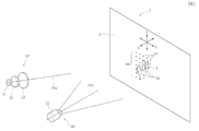
図1と図2に示す三次元測定装置1は、基準面2と、この基準面2に対向する光照射部材10ならびに撮像部材20を有している。
図1と図2に示す基準面2は平面であるが、基準面2は凹凸を有するものであってもよい。
図1と図2には、基準座標としてX-Y-Z座標が示されている。X-Y面は基準面2と平行な面であり、X-Z面は基準面1と垂直な平面である。
光照射部材10は、コヒーレント光源であるレーザ光源11と、レーザー光源から発せられる発散光束14aを平行光束14bに変換するコリメートレンズ12と、コリメートレンズ12で変換された平行光束14bが通過する透過型のホログラム素子13とを有している。レーザ光源11は、人が目視できない近赤外線の波長領域のレーザ光を発する。あるいは、可視光のレーザ光を発するものであってもよい。
ホログラム素子13は位相型の回折格子であり、平行光束14bが回折されて、所定の発散角度を有する照射光束14cが形成され、照射光束14cが基準面2に与えられる。照射光束14cが基準面2に照射されると、基準面2に複数の基準参照スポット31が投影される。複数の基準参照スポット31は、前記レーザ光がホログラム素子13で回折されて形成されるものであり、図4に示す例では、基準面2に小丸形状の基準参照スポット31が形成されている。基準参照スポット31の形状は小丸に限られるものではなく、任意の形状を選択できる。
図4に示すように、平面である基準面2に形成されている基準参照スポット31が、規則的な投影パターンに従って配列されて、基準パターン30が形成される。ここでの「規則的」とは、いずれか1つの基準参照スポット31に着目したときに、その基準参照スポット31とそれぞれの方向で隣接する基準参照スポット31との方向ならびに距離の相対関係が、他の全ての基準参照スポット31において同じである関係を意味している。
図4に示す基準パターン30では、基準参照スポット31が行方向と列方向へ一定のピッチで並ぶ正方格子状に配列している。行方向と列方向は、X-Y方向に対して傾いた状態で基準参照スポット31が照射されている。
図2には、光照射部材10から基準面2に向けて照射される照射光束14cの照射基準線Oaが示されている。照射基準線Oaは、レーザ光源11とコリメートレンズ12ならびにホログラム素子13の光軸に一致している。照射基準線OaはX-Z平面と平行な面内に位置しており、図2の平面図に示すように、照射基準線Oaは基準面2からの垂直線Hに対して90度未満の角度θを有して配置されている。
ホログラム素子13から基準面2に延びる照射光束14cの内部には、それぞれの基準参照スポット31に個別に対応する照射線15が含まれている。ホログラム素子13の回折現象で生成された複数の基準参照スポット31は、それぞれの照射線15と基準面2との交点に生成される。照射光束14cは発散光であるため、厳密には個々の照射線15が拡散角を有しているが、光照射部材10と基準面2との距離を十分に長く確保することで、図2に示すように、照射線15を互いにほぼ平行な配置関係として表すことができる。
図1では、光照射部材10と基準面2との間に被測定物体5が入り込んだ状態が示されている。図1では被測定物体5が人の手である。被測定物体5が入り込むと、その表面に参照スポットが投影される。本明細書では、被測定物体5の表面に投影された参照スポットを移動参照スポット32と呼んでいる。図2に示すように、移動参照スポット32は、個々の照射線15と被測定物体5の表面との交点に生成される。
図1と図2に示すように、撮像部材20はビデオカメラ21を有している。図2には、ビデオカメラ21の撮像基準線Obが示されている。撮像基準線Obはビデオカメラ21の撮像視野の中心線であり、カメラレンズの光軸に一致している。撮像基準線Obは、X-Z面と平行な面内に位置し、この面内において、撮像基準線Obは垂直線Hと平行に配置されている。その結果、照射基準線Oaと撮像基準線Obとが、X-Z面と平行な面内で、角度θを有して対向している。図2に示す実施の形態では角度θは鋭角である。なお、前記角度θを有していれば、照射基準線Oaが垂直線Hと平行であってもよいし、照射基準線Oaと撮像基準線Obの双方が垂直線Hと非平行であってもよい。また角度θは鋭角に限られるものではない。
図3には、ビデオカメラ21で撮像された画像21aが示されている。画像21aには基準参照スポット像31aと移動参照スポット像32aが映し出されている。ここでの基準参照スポット像31aと移動参照スポット像32aは、基準参照スポット31の反射光を取得した像と、移動参照スポット32の反射光を取得した像を意味している。
照射基準線Oaと撮像基準線Obとが所定の角度θ(θは鋭角に限られない)で対向している結果、画像21aにおいては、移動参照スポット像32aが基準参照スポット像31aから延びるエピポーラ線E上に位置する。エピポーラ線Eは、画像21aにおいて、基準参照スポット像31aとその基準参照スポット像31aが移動した移動参照スポット像32aとを結ぶ仮想の直線である。
図2に示すように、撮像部材20では、ビデオカメラ21で取得された画像が、フレーム(コマ)毎にフレームメモリ22に蓄積される。フレームメモリ22には複数のフレーム分の画像が蓄積され、新たなフレームの画像が入力されると、最も古いフレームの画像が廃棄される。
フレームメモリ22に蓄積された画像21aはフレーム毎に画像分析部23に送られて画像が分析され、分析結果が判別部24に送られる。
次に、前記三次元測定装置1の測定動作について説明する。
三次元測定装置1では、基準面2に基準参照スポット31が投影されている状態で、ビデオカメラ21で画像が取得される。その画像は、1フレーム毎にフレームメモリ22に蓄積され、画像分析部23では、前後のフレームの画像を比較してどの参照スポットが移動したかが分析される。
三次元測定装置1では、基準面2に基準参照スポット31が投影されている状態で、ビデオカメラ21で画像が取得される。その画像は、1フレーム毎にフレームメモリ22に蓄積され、画像分析部23では、前後のフレームの画像を比較してどの参照スポットが移動したかが分析される。
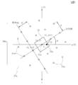
図5は、フレーム毎に取得される画像21aを説明するものであるが、この図には、互いに直交する横軸uと縦軸vが付加されている。横軸uは、図4に示す基準面2におけるX軸に対応し、縦軸vは基準面2におけるY軸に対応している。画像21aにおいて参照スポットが移動するエピポーラ線Eは、照射基準線Oaと撮像基準線Obとの対向状態により決まるもので、必ずしも横軸uや縦軸vと平行になるものではないが、図2と図5に示す実施の形態では、説明の都合上、参照スポットが移動するエピポーラ線Eが、横軸u(X軸)と平行となるように設定されている。
図5には、図4に示す基準参照スポット31の反射像である基準参照スポット像31aが白抜きの小丸で示されている。基準パターン30の照射領域に被測定物体5が存在していないときに取得される第1フレームの画像21aでは、複数の基準参照スポット像31aが、正方格子状に規則的に配列した基準パターン像30aを構成している。
第1フレームに続く第2フレームの画像21aが取得されたときに、被測定物体5が存在してその表面に移動参照スポット32が照射されていると、画像21aに移動参照スポット像32aが現れる。この移動参照スポット32aは元の基準参照スポット像31a上を通るエピポーラ線E上に位置する。図5では、第2フレームの画像21aに現れた移動参照スポット像32aが黒で塗られた小丸で示されている。
また、既に基準パターン30の照射領域に存在している人の手などの被測定物体5が、前記照射領域内で動いたときは、移動参照スポット像32aが、その移動参照スポット像32aの元の位置を通過するエピポーラ線E上を移動する。
図5に示すように、この三次元測定装置1では、第1フレームの画像21aで規則的に配置された基準参照スポット31aが動いておらず、次の第2フレームの画像21aに移動参照スポット像32aが現れたときに、第1フレームの基準参照スポット像31aと第2のフレームの測定対象となる移動参照スポット像32aとの間のエピポーラ線E上での移動距離L1が、第1フレームで既に取得されていた複数の基準参照スポット像31aのうちの移動元でない基準参照スポット像31aと測定対象である移動参照スポット像32aとの最短距離L2よりも短くなるように(L1<L2となるように)撮像条件が決められている。
また、照射領域内に既に存在する被測定物体5が照射領域内で移動するときも、フレーム間で移動した測定対象となる移動参照スポット像32aのエピポーラ線E上での移動距離L1が、先のフレームの複数の移動参照スポット像32aのうちの移動元でない他の移動参照スポット像32aと測定対象となる移動参照スポット像32aとの最短距離L2よりも短くなるように(L1<L2となるように)撮像条件が決められている。
前記条件(L1<L2)は、撮像部材20の焦点距離(f)、光照射部材10と撮像部材10との基線長(B)、フレームレート(ν)、基準参照スポット31の最短ピッチ(d)、ならびに基準面2から垂直な方向での被測定物体5の寸法または移動量に依存する。ここで、被測定物体5は通常は人の手であり、その大きさと移動速度、ならびに基準面2に対するZ方向の操作位置を予め予測できる。そのため、撮像部材20の焦点距離(f)、光照射部材10と撮像部材20との基線長(B)、フレームレート(ν)、基準参照スポット31の最短ピッチ(d)を調整することで、前記条件(L1<L2)を満たすことが可能である。
前記条件(L1<L2)が満たされていると、基準面2の手前に被測定物体5が存在して移動参照スポット像32aが現れたときに、その直前のフレームで得られた画像21aの複数の基準参照スポット像31aのうち、移動参照スポット像32aから最も近い位置にある基準参照スポット像31aを、その移動参照スポット像32aの移動元であると特定することができる。
同様に、既に基準面2の手前に位置する被測定物体5が移動し、移動参照スポット像32aが移動したときにも、その直前のフレームで得られた画像21aの複数の移動参照スポット像32aのうち、対象となる移動参照スポット像32aから最も近い位置にある移動参照スポット像32aを、その移動参照スポット像32aの移動元であると特定することができる。
画像21a上で規則的に配列する基準参照スポット像31aと移動参照スポット像32aには、それぞれが区別できるように予め識別記号が付されている。この識別符号は座標点を表す番号などである。移動参照スポット像32aは、移動すると座標点が変るため、識別符号が変化し、対応する移動参照スポット像32aの識別符号がフレーム間で相違してしまう。ただし、判別部24では、移動後の移動参照スポット像32aから最も近い距離に存在していた基準参照スポット像31aまたは移動参照スポット像32aの識別記号が、移動した参照スポット像32aのものであると特定することが可能になる。
多数の基準参照スポット像31aまたは移動参照スポット像32aのうちの移動した参照スポットを特定することで、被測定物体5の形状や、被測定物体5がどの方向へ移動しているかなどを、判別部24で判別できるようになる。
この特定方法は、ランダムに配列した参照スポットを使用した従来例に比べて演算処理を軽減できる。さらに、画像上でエピポーラ線Eを特定できなくても、移動元の基準参照スポット像31aを特定できるため、被測定物体5の位置や移動を測定する演算処理を容易に行うことができる。
図5に示す実施の形態では、照射線15に相当しているエピポーラ線Eがu軸方向に延びているが、基準パターン像30aの行方向と列方向は、u軸とv軸と平行になっていない。すなわちエピポーラ線Eは、行方向ならびに列方向に角度を有して延びている。基準パターン像30aとエピポーラ線Eとの関係がこのように設定されていると、前記条件(L1<L2)を、さらに設定しやすくなる。
図6(A)は、エピポーラ線Eと、基準パターン像30aの行方向とが一致している例を示し、図6(B)は、エピポーラ線Eが、行方向と列方向に対して45度の角度に延びている例を示している。図6(A)では、基準参照スポット像31aとその次のフレームで得られた移動参照スポット像32aとの距離が(d/2)を超えないように前後のフレームの取得時間を設定しないと、移動参照スポット像32aがどの基準参照スポット像31aから移動したのかが解らなくなる。(d)は基準参照スポット像31aの配列ピッチである。
これに対し、図6(B)では、移動参照スポット像32aと基準参照スポット像31aとの距離が(d/2)を超えたとしても、最短距離に有った基準参照スポット像31aを移動元であると特定することができる。
よって、エピポーラ線Eの方向を、行方向と列方向に対して45度±β(βは45度未満)の角度に設定しておくことで、フレームレートが低くても、移動参照スポット像32aの最短距離に有った基準参照スポット像31aを移動元である、と特定できるようになる。
図5に示す例のように、移動参照スポット像32aが現れたときに、または移動参照スポット像32aが移動したときに、その移動参照スポット像32aが、移動元の基準参照スポット像31aを中心とした一辺の長さが(d)である四角形領域35の内部に位置するようにフレームレートやその他の撮像条件を設定すれば、移動参照スポット像32aから最短に位置していた基準参照スポット像31aを移動元であると特定することが可能である。
次に、前記条件(L1<L2)を成立させるためのパラメータを説明する。
図5に示すように、基準パターン像30a上では基準参照スポット像31aが正方格子状に配列しており、行方向と列方向での基準参照スポット像31aのピッチがdである。
エピポーラ線Eの向きはu軸と平行であり、エピポーラ線Eと行方向の成す角度はΦである。Φは、-(π/4)<Φ≦(π/4)である。
図5に示すように、基準パターン像30a上では基準参照スポット像31aが正方格子状に配列しており、行方向と列方向での基準参照スポット像31aのピッチがdである。
エピポーラ線Eの向きはu軸と平行であり、エピポーラ線Eと行方向の成す角度はΦである。Φは、-(π/4)<Φ≦(π/4)である。
以下では、i行でj列に位置する基準参照スポット像31aを識別記号α=(i,j)で表し、行方向においてその前後に位置する基準参照スポット像31aの識別記号をそれぞれ、α+=(i,j+1)、α-=(i,j-1)で表している。
時刻t=tk-1のフレームにおけるα=(i,j)の基準参照スポット像31aの座標を以下の数1とすると、α+=(i,j+1)とα-=(i,j-1)の基準参照スポット像31aは、まとめてα±として、以下の数2で表すことができる。


次のフレーム取得時刻t=tk=tk-1+Δtにおけるα=(i,j)の基準参照スポット像31aの座標は、m´α(tk)=(u´α(tk),v´α(tk))である。u´α(tk)とv´α(tk)は、以下の数3で表される。

数3におけるZα(tk-1),Zα(tk)は、それぞれ、時刻tk-1ならびにtkにおけるα=(i,j)の基準参照スポット像31aのu-v-Zの三次元座標上のZ成分である。なお、u-v座標は画像座標であり、Zは世界座標(空間座標)のZ成分である。すなわちu-vとZは別々の座標系である。fはビデオカメラ21の焦点距離であり、Bは光照射部材10と撮像部材20との基線長である。また、ΔZα(tk)=Zα(tk)-Zα(tk-1)であり、Δu’α(tk)=u’α(tk)-u’α(tk-1)である。
図5に示す距離L1,L2は、以下の数4で定義でき、さらに数5に整理できる。

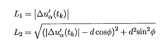
ここで、L1<L2となる条件を探すと、数5から、v´α(tk)に対して以下の数6の条件が導かれる。
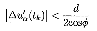
また、図3を用いてΔZα(tk)に対する条件式を求めると、2fBcosΦ-Zα(tk-1)d>0の場合には、以下の数7となる。

2fBcosΦ-Zα(tk-1)d<0のときは、視差が以下の数8を満たすため、ΔZα(tk)の上限がなくなり、数9となる。

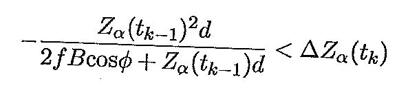
被測定物体5が存在しているときのZ成分の範囲をZmin≦Z≦Zmaxとすると、Z=Zminのときに数7は最も厳しい条件を与え、以下の数10となる。

以上から、焦点距離(f)、基線長(B)、基準パターン30aの配列ピッチ(d)と角度(Φ)ならびに、基準参照スポット像31aのZ方向の移動最短距離(Zmin)を調整することで、条件(L1<L2)を実現できる。数10で、条件(L1<L2)を実現することで、どの基準参照スポット像31aが動いたかを知ることができ、その結果、被測定物5の寸法と形状とを把握することができる。
なお、被測定物5が既に基準パターン30の照射領域に有り、フレーム間で被測定物5が移動する場合には、ΔZα(tk)の代わりに、被測定物体5のZ方向の移動速度であるΔVα(tk)=ΔZα(tk)/Δtを用いて数10を書き換えると、以下の数11となる。数11のνはフレームレートであり、Δt=1/νである。

以上から、焦点距離(f)、基線長(B)フレームレート(ν)、基準パターン30aの配列ピッチ(d)と角度(Φ)ならびに、基準参照スポット像31aのZ方向の移動最短距離(Zmin)を調整することで、条件(L1<L2)を実現可能な操作対象の動作速度を定義することができる。数11で、条件(L1<L2)を実現することで、被測定物5の移動量を把握できる。
前記実施の形態では、基準参照スポット像31aと移動参照スポット像32aとの距離L1を算出して、最も近い距離に存在していた基準参照スポット31aと移動参照スポット像32aとを関連付けている。しかし、本発明は、基準参照スポット像31aおよび移動参照スポット像32aの座標を比較することで距離を算出するのではなく、距離の算出手法を変えても良い。具体的には各スポット像の座標変換を行った後に比較を行っても良い。
例えば、光照射部材10から照射されるスポット像を片方の画像とみなすことで、撮像部材20とのステレオ系として考えることができる。この場合には、光照射部材10から出射されるスポット像と撮像部材20内のスポット像の間の変換を表す射影変換行列を定義することができるため、射影変換を行ってスポット像を整列させた後に距離を算出することができる。
ここでの射影変換行列とは、ステレオ画像間の点の変換行列を意味している。レーザー・カメラ系も、レーザーの投光パターンを片方の画像とみなすことでステレオ系と考えることができるため、投光パターンとカメラ画像内のレーザー点の間の変換を表す射影変換行列を定義することができる。
その際には、各フレームで用いる射影変換行列は、前フレームで求めた射影変換行列を、前後フレーム両方のスポット像に対して用いるものとする。
前後フレームで共通の射影変換行列を用いる理由は、それぞれのフレームで求めた射影変換行列を用いてそれぞれのスポット像を変換したとすると、変換先の基準参照スポット像31aが同一であるため、両方のフレームのスポット像が重なることになる。射影変換行列を求める際に、基準参照スポット像31aと移動参照スポット像32aとが正しく対応付けされていれば問題ないが、対応付けができていない際には変換後のスポット像が行または列ごとずれて重なってしまう。この場合は、フレーム間のスポット像の対応付けは最も近い距離のものを対応付ける最近傍探索というよりも、基準参照スポット像31aの対応付けの問題になってしまう。
なお、射影変換は各スポット像を全て含む画像全体に対して一回行うか、または画像を分割し、その分割されたそれぞれの領域で射影変換行列を行い、結果を組み合わせる、のいずれかを選択すれば良い。
射影変換を用いた演算プロセスは以下の通りである。
仮想画像上のα番目の格子点座標を(uα,vα)、カメラ画像上の対応する格子点座標を(u´α,v´α)、カメラ画像座標を仮想画像に変換する射影変換行列を以下の数12とすると、変換式は数13で与えられる。数13でのsはスカラーである。
仮想画像上のα番目の格子点座標を(uα,vα)、カメラ画像上の対応する格子点座標を(u´α,v´α)、カメラ画像座標を仮想画像に変換する射影変換行列を以下の数12とすると、変換式は数13で与えられる。数13でのsはスカラーである。

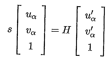
射影変換行列Hの自由度は8であり、4つ以上の仮想画像とカメラ画像上の格子点の組があれば、最小二乗法によりHを求めることができる。
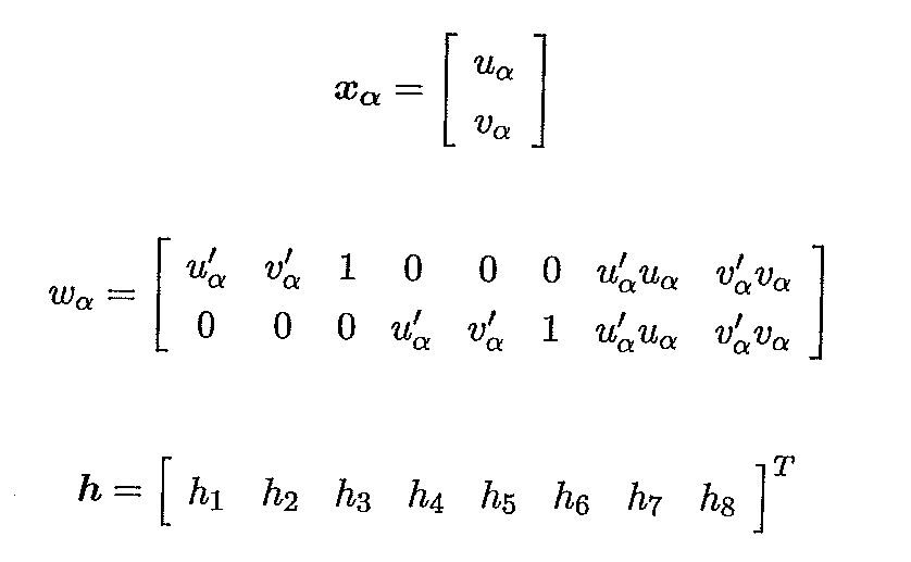
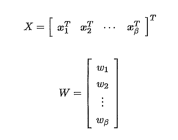
数15のように定義すると、β≧4の場合に、hを数16のように求めることができる。ここでW+はWの疑似逆行列を表す。

この射影変換行列を使用する手法は、被測定物が既にレーザーの照射範囲にあり、フレーム間で被測定物が移動する場合でも同様に計算できる。
1 三次元測定装置
2 基準面
5 被測定物体
10 光照射部材
11 レーザ光源
12 コリメートレンズ
13 ホログラム素子
15 照射線
20 撮像部材
21 ビデオカメラ
30 基準パターン
30a 基準パターン像
31 基準参照スポット
31a 基準参照スポット像
32 移動参照スポット
32a 基準スポット像
E エピポーラ線
Oa 照射基準線
Ob 撮像基準線
2 基準面
5 被測定物体
10 光照射部材
11 レーザ光源
12 コリメートレンズ
13 ホログラム素子
15 照射線
20 撮像部材
21 ビデオカメラ
30 基準パターン
30a 基準パターン像
31 基準参照スポット
31a 基準参照スポット像
32 移動参照スポット
32a 基準スポット像
E エピポーラ線
Oa 照射基準線
Ob 撮像基準線
Claims (7)
- コヒーレント光を基準面に照射して複数の参照スポットを形成する光照射部材と、参照スポット像を取得する撮像部材と、判別部とが設けられており、
前記基準面では、複数の参照スポットが基準パターン上で規則的に配列し、被測定物体が前記光照射部と前記基準面との間に位置したときに、前記基準パターン上に位置していた参照スポットが、被測定物体の表面に移動し、
前記判別部では、前記画像上で参照スポット像が移動したら、移動後の参照スポット像が、基準パターン上に位置していた複数の参照スポット像のうちの最も距離が短いものから移動したと判定し、これにより被測定物体の存在が判別されることを特徴とする三次元測定装置。 - 参照スポットが被測定物の表面に移動する際に、前記画像の連続する2つのフレームの間で参照スポット像が移動する距離は、移動後の参照スポット像と基準パターン上の他の参照スポット像との距離よりも短くなるように、撮像条件が決められている請求項1記載の三次元測定装置。
- 前記撮像条件は、前記撮像部材の焦点距離(f)、前記光照射部材と前記撮像部材との基線長(B)、フレームレート(ν)、基準パターンでの参照スポット像の最短ピッチ(d)、ならびに前記基準面から垂直な方向での被測定物体の寸法または移動量、に基づいて決められる請求項2記載の三次元測定装置。
- 以下の数10を使用することで、被測定物の形状と寸法の少なくとも一方を求める請求項3記載の三次元測定装置。

- 以下の数11を使用することで、被測定物の移動量を求める請求項3記載の三次元測定装置。

- それぞれの参照スポットは、前記光照射部材から延びる照射線上に位置し、前記撮像部材による撮像方向が、それぞれの前記照射線と所定角を有して対向しており、
前記基準パターンに位置していた参照スポットが被測定物体の表面に移動したときに、画像上に現れる参照スポット像が、前記照射線に対応するエピポーラ線上を移動する請求項1ないし5のいずれかに記載の三次元測定装置。 - 前記基準パターンでは、複数の参照スポットが、互いに直交する行方向と列方向の双方に一定のピッチで配列しており、前記エピポーラ線は前記行方向と前記列方向の双方に対して所定の角度を成すように、基準パターンでの参照スポットの配列方向が決められている請求項6記載の三次元測定装置。
Applications Claiming Priority (2)
| Application Number | Priority Date | Filing Date | Title |
|---|---|---|---|
| JP2014155876A JP6337677B2 (ja) | 2014-07-31 | 2014-07-31 | 三次元測定装置 |
| JP2014-155876 | 2014-07-31 |
Publications (1)
| Publication Number | Publication Date |
|---|---|
| WO2016017489A1 true WO2016017489A1 (ja) | 2016-02-04 |
Family
ID=55217390
Family Applications (1)
| Application Number | Title | Priority Date | Filing Date |
|---|---|---|---|
| PCT/JP2015/070782 Ceased WO2016017489A1 (ja) | 2014-07-31 | 2015-07-22 | 三次元測定装置 |
Country Status (2)
| Country | Link |
|---|---|
| JP (1) | JP6337677B2 (ja) |
| WO (1) | WO2016017489A1 (ja) |
Citations (2)
| Publication number | Priority date | Publication date | Assignee | Title |
|---|---|---|---|---|
| JPH0342507A (ja) * | 1989-07-11 | 1991-02-22 | Omron Corp | 位置測定装置 |
| JP2002122417A (ja) * | 2000-10-16 | 2002-04-26 | Sumitomo Osaka Cement Co Ltd | 三次元形状測定装置 |
Family Cites Families (2)
| Publication number | Priority date | Publication date | Assignee | Title |
|---|---|---|---|---|
| JP3677444B2 (ja) * | 2000-10-16 | 2005-08-03 | 住友大阪セメント株式会社 | 三次元形状測定装置 |
| JP3782815B2 (ja) * | 2004-02-04 | 2006-06-07 | 住友大阪セメント株式会社 | 呼吸解析装置 |
-
2014
- 2014-07-31 JP JP2014155876A patent/JP6337677B2/ja active Active
-
2015
- 2015-07-22 WO PCT/JP2015/070782 patent/WO2016017489A1/ja not_active Ceased
Patent Citations (2)
| Publication number | Priority date | Publication date | Assignee | Title |
|---|---|---|---|---|
| JPH0342507A (ja) * | 1989-07-11 | 1991-02-22 | Omron Corp | 位置測定装置 |
| JP2002122417A (ja) * | 2000-10-16 | 2002-04-26 | Sumitomo Osaka Cement Co Ltd | 三次元形状測定装置 |
Non-Patent Citations (1)
| Title |
|---|
| DIPANDA, ALBERT ET AL.: "Efficient correspondence problem-solving in 3-D shape reconstruction using a structured light system", OPTICAL ENGINEERING, vol. 44, no. 9, 27 September 2005 (2005-09-27), pages 1 - 14 * |
Also Published As
| Publication number | Publication date |
|---|---|
| JP6337677B2 (ja) | 2018-06-06 |
| JP2016033463A (ja) | 2016-03-10 |
Similar Documents
| Publication | Publication Date | Title |
|---|---|---|
| JP6876776B2 (ja) | 距離センサ | |
| JP7133554B2 (ja) | 焦点調整可能な画像センサを含む距離センサ | |
| JP6761817B2 (ja) | 物体までの距離を算出するための方法 | |
| JPWO2006013635A1 (ja) | 3次元形状計測方法及びその装置 | |
| JP6484072B2 (ja) | 物体検出装置 | |
| JP6484071B2 (ja) | 物体検出装置 | |
| JP2020531849A5 (ja) | ||
| JP4568800B2 (ja) | 小滴の状態計測装置及び該装置におけるカメラの校正方法 | |
| CN107076553B (zh) | 使用结构光的增强对象检测 | |
| CN109391758A (zh) | 对样品保持器中的样品进行成像 | |
| JP2012237604A (ja) | 情報取得装置、投射装置および物体検出装置 | |
| JP2009198241A (ja) | 計測器 | |
| JP2010243273A (ja) | 円柱形状を有する物体の計測方法および計測装置 | |
| JP2014021017A (ja) | 情報取得装置および物体検出装置 | |
| JP6337677B2 (ja) | 三次元測定装置 | |
| Angel-Toro et al. | Speckle decorrelation influence on measurements quality in vortex metrology | |
| JP6388806B2 (ja) | 射影画像生成装置と射影画像生成プログラムと射影画像生成方法 | |
| JP2007327966A (ja) | 光源モジュールおよびこれを用いた位置計測システム | |
| JP6436349B2 (ja) | 物体検出装置 | |
| JP2014132219A (ja) | 情報取得装置および物体検出装置 | |
| CN107835931A (zh) | 监测三维实体的线性尺寸的方法 | |
| JP2014085282A (ja) | 情報取得装置および物体検出装置 | |
| JP2006308452A (ja) | 3次元形状計測方法および装置 | |
| JP3976054B2 (ja) | 位置計測システム | |
| JP2725207B2 (ja) | 位置測定装置 |
Legal Events
| Date | Code | Title | Description |
|---|---|---|---|
| 121 | Ep: the epo has been informed by wipo that ep was designated in this application |
Ref document number: 15826602 Country of ref document: EP Kind code of ref document: A1 |
|
| NENP | Non-entry into the national phase |
Ref country code: DE |
|
| 122 | Ep: pct application non-entry in european phase |
Ref document number: 15826602 Country of ref document: EP Kind code of ref document: A1 |