WO2016017456A1 - 処理装置、殺菌装置、殺菌水及び殺菌方法 - Google Patents
処理装置、殺菌装置、殺菌水及び殺菌方法 Download PDFInfo
- Publication number
- WO2016017456A1 WO2016017456A1 PCT/JP2015/070520 JP2015070520W WO2016017456A1 WO 2016017456 A1 WO2016017456 A1 WO 2016017456A1 JP 2015070520 W JP2015070520 W JP 2015070520W WO 2016017456 A1 WO2016017456 A1 WO 2016017456A1
- Authority
- WO
- WIPO (PCT)
- Prior art keywords
- liquid
- treated
- plasma
- processing apparatus
- plasma generation
- Prior art date
Links
- 230000001954 sterilising effect Effects 0.000 title claims abstract description 44
- XLYOFNOQVPJJNP-UHFFFAOYSA-N water Substances O XLYOFNOQVPJJNP-UHFFFAOYSA-N 0.000 title claims abstract description 24
- 238000000034 method Methods 0.000 title claims abstract description 16
- 238000004659 sterilization and disinfection Methods 0.000 title claims abstract description 14
- 239000007788 liquid Substances 0.000 claims abstract description 225
- 230000002378 acidificating effect Effects 0.000 claims description 15
- 239000000645 desinfectant Substances 0.000 claims 1
- 239000008223 sterile water Substances 0.000 abstract 1
- 239000007789 gas Substances 0.000 description 34
- 239000004020 conductor Substances 0.000 description 10
- 239000007795 chemical reaction product Substances 0.000 description 9
- 230000000844 anti-bacterial effect Effects 0.000 description 8
- IJGRMHOSHXDMSA-UHFFFAOYSA-N Atomic nitrogen Chemical compound N#N IJGRMHOSHXDMSA-UHFFFAOYSA-N 0.000 description 4
- 239000000919 ceramic Substances 0.000 description 4
- 230000000694 effects Effects 0.000 description 3
- 239000012530 fluid Substances 0.000 description 3
- XEEYBQQBJWHFJM-UHFFFAOYSA-N Iron Chemical compound [Fe] XEEYBQQBJWHFJM-UHFFFAOYSA-N 0.000 description 2
- VYPSYNLAJGMNEJ-UHFFFAOYSA-N Silicium dioxide Chemical compound O=[Si]=O VYPSYNLAJGMNEJ-UHFFFAOYSA-N 0.000 description 2
- GWEVSGVZZGPLCZ-UHFFFAOYSA-N Titan oxide Chemical compound O=[Ti]=O GWEVSGVZZGPLCZ-UHFFFAOYSA-N 0.000 description 2
- MCMNRKCIXSYSNV-UHFFFAOYSA-N Zirconium dioxide Chemical compound O=[Zr]=O MCMNRKCIXSYSNV-UHFFFAOYSA-N 0.000 description 2
- QVGXLLKOCUKJST-UHFFFAOYSA-N atomic oxygen Chemical compound [O] QVGXLLKOCUKJST-UHFFFAOYSA-N 0.000 description 2
- 238000004090 dissolution Methods 0.000 description 2
- 230000002070 germicidal effect Effects 0.000 description 2
- 229910052757 nitrogen Inorganic materials 0.000 description 2
- 239000005416 organic matter Substances 0.000 description 2
- 239000001301 oxygen Substances 0.000 description 2
- 229910052760 oxygen Inorganic materials 0.000 description 2
- BASFCYQUMIYNBI-UHFFFAOYSA-N platinum Chemical compound [Pt] BASFCYQUMIYNBI-UHFFFAOYSA-N 0.000 description 2
- 241000894007 species Species 0.000 description 2
- 239000000126 substance Substances 0.000 description 2
- 241000894006 Bacteria Species 0.000 description 1
- RYGMFSIKBFXOCR-UHFFFAOYSA-N Copper Chemical compound [Cu] RYGMFSIKBFXOCR-UHFFFAOYSA-N 0.000 description 1
- 239000002253 acid Substances 0.000 description 1
- 230000004913 activation Effects 0.000 description 1
- PNEYBMLMFCGWSK-UHFFFAOYSA-N aluminium oxide Inorganic materials [O-2].[O-2].[O-2].[Al+3].[Al+3] PNEYBMLMFCGWSK-UHFFFAOYSA-N 0.000 description 1
- 238000004891 communication Methods 0.000 description 1
- 239000012141 concentrate Substances 0.000 description 1
- 229910052802 copper Inorganic materials 0.000 description 1
- 239000010949 copper Substances 0.000 description 1
- 230000007423 decrease Effects 0.000 description 1
- 230000005684 electric field Effects 0.000 description 1
- 238000000265 homogenisation Methods 0.000 description 1
- 229910052742 iron Inorganic materials 0.000 description 1
- 230000001678 irradiating effect Effects 0.000 description 1
- 239000003002 pH adjusting agent Substances 0.000 description 1
- 229910052697 platinum Inorganic materials 0.000 description 1
- 238000005086 pumping Methods 0.000 description 1
- 239000000377 silicon dioxide Substances 0.000 description 1
- 229910001220 stainless steel Inorganic materials 0.000 description 1
- 239000010935 stainless steel Substances 0.000 description 1
- WFKWXMTUELFFGS-UHFFFAOYSA-N tungsten Chemical compound [W] WFKWXMTUELFFGS-UHFFFAOYSA-N 0.000 description 1
- 229910052721 tungsten Inorganic materials 0.000 description 1
- 239000010937 tungsten Substances 0.000 description 1
Images


Classifications
-
- A—HUMAN NECESSITIES
- A61—MEDICAL OR VETERINARY SCIENCE; HYGIENE
- A61L—METHODS OR APPARATUS FOR STERILISING MATERIALS OR OBJECTS IN GENERAL; DISINFECTION, STERILISATION OR DEODORISATION OF AIR; CHEMICAL ASPECTS OF BANDAGES, DRESSINGS, ABSORBENT PADS OR SURGICAL ARTICLES; MATERIALS FOR BANDAGES, DRESSINGS, ABSORBENT PADS OR SURGICAL ARTICLES
- A61L2/00—Methods or apparatus for disinfecting or sterilising materials or objects other than foodstuffs or contact lenses; Accessories therefor
- A61L2/16—Methods or apparatus for disinfecting or sterilising materials or objects other than foodstuffs or contact lenses; Accessories therefor using chemical substances
- A61L2/18—Liquid substances or solutions comprising solids or dissolved gases
-
- A—HUMAN NECESSITIES
- A23—FOODS OR FOODSTUFFS; TREATMENT THEREOF, NOT COVERED BY OTHER CLASSES
- A23L—FOODS, FOODSTUFFS, OR NON-ALCOHOLIC BEVERAGES, NOT COVERED BY SUBCLASSES A21D OR A23B-A23J; THEIR PREPARATION OR TREATMENT, e.g. COOKING, MODIFICATION OF NUTRITIVE QUALITIES, PHYSICAL TREATMENT; PRESERVATION OF FOODS OR FOODSTUFFS, IN GENERAL
- A23L3/00—Preservation of foods or foodstuffs, in general, e.g. pasteurising, sterilising, specially adapted for foods or foodstuffs
-
- A—HUMAN NECESSITIES
- A61—MEDICAL OR VETERINARY SCIENCE; HYGIENE
- A61L—METHODS OR APPARATUS FOR STERILISING MATERIALS OR OBJECTS IN GENERAL; DISINFECTION, STERILISATION OR DEODORISATION OF AIR; CHEMICAL ASPECTS OF BANDAGES, DRESSINGS, ABSORBENT PADS OR SURGICAL ARTICLES; MATERIALS FOR BANDAGES, DRESSINGS, ABSORBENT PADS OR SURGICAL ARTICLES
- A61L2/00—Methods or apparatus for disinfecting or sterilising materials or objects other than foodstuffs or contact lenses; Accessories therefor
- A61L2/26—Accessories or devices or components used for biocidal treatment
-
- B—PERFORMING OPERATIONS; TRANSPORTING
- B01—PHYSICAL OR CHEMICAL PROCESSES OR APPARATUS IN GENERAL
- B01F—MIXING, e.g. DISSOLVING, EMULSIFYING OR DISPERSING
- B01F23/00—Mixing according to the phases to be mixed, e.g. dispersing or emulsifying
- B01F23/20—Mixing gases with liquids
-
- B—PERFORMING OPERATIONS; TRANSPORTING
- B01—PHYSICAL OR CHEMICAL PROCESSES OR APPARATUS IN GENERAL
- B01F—MIXING, e.g. DISSOLVING, EMULSIFYING OR DISPERSING
- B01F23/00—Mixing according to the phases to be mixed, e.g. dispersing or emulsifying
- B01F23/20—Mixing gases with liquids
- B01F23/23—Mixing gases with liquids by introducing gases into liquid media, e.g. for producing aerated liquids
- B01F23/232—Mixing gases with liquids by introducing gases into liquid media, e.g. for producing aerated liquids using flow-mixing means for introducing the gases, e.g. baffles
- B01F23/2323—Mixing gases with liquids by introducing gases into liquid media, e.g. for producing aerated liquids using flow-mixing means for introducing the gases, e.g. baffles by circulating the flow in guiding constructions or conduits
-
- B—PERFORMING OPERATIONS; TRANSPORTING
- B01—PHYSICAL OR CHEMICAL PROCESSES OR APPARATUS IN GENERAL
- B01F—MIXING, e.g. DISSOLVING, EMULSIFYING OR DISPERSING
- B01F25/00—Flow mixers; Mixers for falling materials, e.g. solid particles
- B01F25/30—Injector mixers
-
- B—PERFORMING OPERATIONS; TRANSPORTING
- B01—PHYSICAL OR CHEMICAL PROCESSES OR APPARATUS IN GENERAL
- B01F—MIXING, e.g. DISSOLVING, EMULSIFYING OR DISPERSING
- B01F25/00—Flow mixers; Mixers for falling materials, e.g. solid particles
- B01F25/30—Injector mixers
- B01F25/31—Injector mixers in conduits or tubes through which the main component flows
- B01F25/312—Injector mixers in conduits or tubes through which the main component flows with Venturi elements; Details thereof
-
- B—PERFORMING OPERATIONS; TRANSPORTING
- B01—PHYSICAL OR CHEMICAL PROCESSES OR APPARATUS IN GENERAL
- B01F—MIXING, e.g. DISSOLVING, EMULSIFYING OR DISPERSING
- B01F35/00—Accessories for mixers; Auxiliary operations or auxiliary devices; Parts or details of general application
- B01F35/71—Feed mechanisms
- B01F35/712—Feed mechanisms for feeding fluids
-
- B—PERFORMING OPERATIONS; TRANSPORTING
- B01—PHYSICAL OR CHEMICAL PROCESSES OR APPARATUS IN GENERAL
- B01J—CHEMICAL OR PHYSICAL PROCESSES, e.g. CATALYSIS OR COLLOID CHEMISTRY; THEIR RELEVANT APPARATUS
- B01J19/00—Chemical, physical or physico-chemical processes in general; Their relevant apparatus
- B01J19/08—Processes employing the direct application of electric or wave energy, or particle radiation; Apparatus therefor
- B01J19/087—Processes employing the direct application of electric or wave energy, or particle radiation; Apparatus therefor employing electric or magnetic energy
- B01J19/088—Processes employing the direct application of electric or wave energy, or particle radiation; Apparatus therefor employing electric or magnetic energy giving rise to electric discharges
-
- C—CHEMISTRY; METALLURGY
- C02—TREATMENT OF WATER, WASTE WATER, SEWAGE, OR SLUDGE
- C02F—TREATMENT OF WATER, WASTE WATER, SEWAGE, OR SLUDGE
- C02F1/00—Treatment of water, waste water, or sewage
- C02F1/46—Treatment of water, waste water, or sewage by electrochemical methods
- C02F1/4608—Treatment of water, waste water, or sewage by electrochemical methods using electrical discharges
-
- C—CHEMISTRY; METALLURGY
- C02—TREATMENT OF WATER, WASTE WATER, SEWAGE, OR SLUDGE
- C02F—TREATMENT OF WATER, WASTE WATER, SEWAGE, OR SLUDGE
- C02F1/00—Treatment of water, waste water, or sewage
- C02F1/50—Treatment of water, waste water, or sewage by addition or application of a germicide or by oligodynamic treatment
-
- H—ELECTRICITY
- H05—ELECTRIC TECHNIQUES NOT OTHERWISE PROVIDED FOR
- H05H—PLASMA TECHNIQUE; PRODUCTION OF ACCELERATED ELECTRICALLY-CHARGED PARTICLES OR OF NEUTRONS; PRODUCTION OR ACCELERATION OF NEUTRAL MOLECULAR OR ATOMIC BEAMS
- H05H1/00—Generating plasma; Handling plasma
- H05H1/24—Generating plasma
-
- A—HUMAN NECESSITIES
- A23—FOODS OR FOODSTUFFS; TREATMENT THEREOF, NOT COVERED BY OTHER CLASSES
- A23V—INDEXING SCHEME RELATING TO FOODS, FOODSTUFFS OR NON-ALCOHOLIC BEVERAGES AND LACTIC OR PROPIONIC ACID BACTERIA USED IN FOODSTUFFS OR FOOD PREPARATION
- A23V2002/00—Food compositions, function of food ingredients or processes for food or foodstuffs
-
- B—PERFORMING OPERATIONS; TRANSPORTING
- B01—PHYSICAL OR CHEMICAL PROCESSES OR APPARATUS IN GENERAL
- B01J—CHEMICAL OR PHYSICAL PROCESSES, e.g. CATALYSIS OR COLLOID CHEMISTRY; THEIR RELEVANT APPARATUS
- B01J2219/00—Chemical, physical or physico-chemical processes in general; Their relevant apparatus
- B01J2219/08—Processes employing the direct application of electric or wave energy, or particle radiation; Apparatus therefor
- B01J2219/0803—Processes employing the direct application of electric or wave energy, or particle radiation; Apparatus therefor employing electric or magnetic energy
- B01J2219/0805—Processes employing the direct application of electric or wave energy, or particle radiation; Apparatus therefor employing electric or magnetic energy giving rise to electric discharges
- B01J2219/0807—Processes employing the direct application of electric or wave energy, or particle radiation; Apparatus therefor employing electric or magnetic energy giving rise to electric discharges involving electrodes
- B01J2219/0824—Details relating to the shape of the electrodes
- B01J2219/0832—Details relating to the shape of the electrodes essentially toroidal
- B01J2219/0833—Details relating to the shape of the electrodes essentially toroidal forming part of a full circle
-
- B—PERFORMING OPERATIONS; TRANSPORTING
- B01—PHYSICAL OR CHEMICAL PROCESSES OR APPARATUS IN GENERAL
- B01J—CHEMICAL OR PHYSICAL PROCESSES, e.g. CATALYSIS OR COLLOID CHEMISTRY; THEIR RELEVANT APPARATUS
- B01J2219/00—Chemical, physical or physico-chemical processes in general; Their relevant apparatus
- B01J2219/08—Processes employing the direct application of electric or wave energy, or particle radiation; Apparatus therefor
- B01J2219/0873—Materials to be treated
- B01J2219/0881—Two or more materials
- B01J2219/0884—Gas-liquid
-
- B—PERFORMING OPERATIONS; TRANSPORTING
- B01—PHYSICAL OR CHEMICAL PROCESSES OR APPARATUS IN GENERAL
- B01J—CHEMICAL OR PHYSICAL PROCESSES, e.g. CATALYSIS OR COLLOID CHEMISTRY; THEIR RELEVANT APPARATUS
- B01J2219/00—Chemical, physical or physico-chemical processes in general; Their relevant apparatus
- B01J2219/08—Processes employing the direct application of electric or wave energy, or particle radiation; Apparatus therefor
- B01J2219/0894—Processes carried out in the presence of a plasma
- B01J2219/0896—Cold plasma
-
- C—CHEMISTRY; METALLURGY
- C02—TREATMENT OF WATER, WASTE WATER, SEWAGE, OR SLUDGE
- C02F—TREATMENT OF WATER, WASTE WATER, SEWAGE, OR SLUDGE
- C02F2201/00—Apparatus for treatment of water, waste water or sewage
- C02F2201/46—Apparatus for electrochemical processes
- C02F2201/461—Electrolysis apparatus
- C02F2201/46105—Details relating to the electrolytic devices
- C02F2201/4616—Power supply
- C02F2201/46175—Electrical pulses
-
- C—CHEMISTRY; METALLURGY
- C02—TREATMENT OF WATER, WASTE WATER, SEWAGE, OR SLUDGE
- C02F—TREATMENT OF WATER, WASTE WATER, SEWAGE, OR SLUDGE
- C02F2301/00—General aspects of water treatment
- C02F2301/04—Flow arrangements
- C02F2301/046—Recirculation with an external loop
-
- C—CHEMISTRY; METALLURGY
- C02—TREATMENT OF WATER, WASTE WATER, SEWAGE, OR SLUDGE
- C02F—TREATMENT OF WATER, WASTE WATER, SEWAGE, OR SLUDGE
- C02F2303/00—Specific treatment goals
- C02F2303/04—Disinfection
-
- C—CHEMISTRY; METALLURGY
- C02—TREATMENT OF WATER, WASTE WATER, SEWAGE, OR SLUDGE
- C02F—TREATMENT OF WATER, WASTE WATER, SEWAGE, OR SLUDGE
- C02F2305/00—Use of specific compounds during water treatment
- C02F2305/02—Specific form of oxidant
- C02F2305/023—Reactive oxygen species, singlet oxygen, OH radical
Definitions
- the present invention relates to a processing apparatus using plasma, a sterilizer, sterilizing water, and a sterilizing method.
- the liquid processing apparatus disclosed in Japanese Patent No. 5099612 is configured by integrally directly connecting a gas discharge unit and a microbubble generation unit, and is immersed in the liquid to be treated that has filled the liquid tank.
- the gas discharge unit is connected by a gas supply unit that supplies a gas and a gas supply pipe.
- the microbubble generation part is connected by the circulation pump and the liquid supply pipe which are immersed in the liquid.
- a gas discharge part makes gas a plasma by gas discharge between both electrodes under atmospheric pressure, and generates activation gas.
- the microbubble generation unit microbubbles the activated gas introduced from the gas discharge unit into bubbles having a diameter of 1 to 100 ⁇ m in the liquid to be treated to form a gas-liquid mixed fluid, and the gas-liquid mixed fluid is treated to be liquid to be treated Supply in.
- the liquid generated to have a pH of 4.8 or less is contacted with radicals generated by plasma to perform sterilization.
- the sterilizer to perform this method is a sterilizer for bacteria present in or on the surface of the liquid, and the pH adjuster adjusts the pH of the liquid to be 4.8 or less, and the plasma for irradiating the plasma to the liquid And a generator.
- the present invention has been made in consideration of such problems, and it is possible to supply a high concentration of microbubbles in the liquid to be treated without immersing the device itself in the liquid to be treated, the liquid to be treated It is an object of the present invention to provide a processing apparatus capable of reducing damage to an object to be treated (eg, an organic substance such as a food) even if the acid water is acidic water.
- an object to be treated eg, an organic substance such as a food
- Another object of the present invention is to provide a sterilizing apparatus capable of producing sterilizing water containing a large amount of radicals having a bactericidal effect by using the above-mentioned treatment apparatus according to the present invention.
- Another object of the present invention is to provide germicidal water containing a large amount of germicidally effective radicals.
- Another object of the present invention is to provide a sterilization method capable of efficiently sterilizing an object to be treated with sterilizing water containing a large amount of germicidal effects.
- a processing apparatus is a liquid storage portion having a liquid to be treated, a plasma generation portion generating plasma on the liquid surface of the liquid to be treated, and bubbles containing the generated plasma. And the bubble supply part which produces
- the processing apparatus generates plasma on the liquid surface of the liquid to be treated, generates bubbles containing the generated plasma on the liquid surface, and supplies the bubbles to the liquid to be treated.
- "On the liquid surface” means above the liquid surface or above the liquid surface.
- the liquid to be treated may be adjusted to be acidic.
- the liquid to be treated is adjusted to an acidity, usually, the object to be treated immersed in the liquid to be treated will be damaged, but the concentration of air bubbles supplied to the liquid to be treated may be increased. Because it is possible, it is possible to reduce the damage to the object to be treated.
- the liquid to be treated is adjusted to be acidic, the dissolution rate of the gas in the bubbles supplied to the liquid to be treated is improved, and the reaction product with plasma active species or active species is efficiently introduced into the liquid. It can be dissolved well.
- the resistance (contact resistance) with the air bubbles is reduced, and the air bubbles can easily move in the liquid to be treated.
- radicals having a bactericidal effect can be widely spread in a short time, the concentration of radicals in the liquid to be treated can be increased, and the liquid to be treated can be, for example, bactericidal water having a high bactericidal effect.
- the bubble supply unit may generate the bubble by introducing the plasma from the plasma generation unit into the liquid supplied to the liquid storage unit.
- the liquid is supplied to a liquid storage unit having the liquid to be treated. During the supply, plasma is introduced into the liquid to generate bubbles containing the plasma in the liquid. The generated air bubbles are supplied to the liquid to be treated together with the liquid. As a result, it is possible to generate plasma on the liquid surface of the liquid to be treated, generate bubbles on the liquid surface containing the generated plasma, and supply it to the liquid to be treated.
- the bubble supply unit has an aspirator including a venturi unit in the middle of the flow passage for supplying the liquid to the liquid storage unit, and the plasma from the plasma generation unit is passed through the venturi unit.
- the bubbles may be generated by introducing them.
- the pressure decreases due to the Venturi effect as the flow velocity increases at the venturi section. Therefore, the plasma generated in the plasma generation portion flows into the venturi portion where the pressure is lowered, and a bubble containing the plasma in the liquid is generated.
- the liquid containing bubbles is supplied into the liquid to be treated in the liquid reservoir through the aspirator.
- microbubbles increase the contact area between the plasma active species or the reaction product with the plasma active species and the liquid, and increase the internal pressure accompanying the miniaturization of the bubbles and improve the solubility, so that the plasma active species or plasma active species Can be efficiently dissolved in the liquid to be treated.
- the plasma generation part and the bubble supply part are disposed in the space, and the plasma generation part is Plasma may be generated based on the introduction of the gas for plasma generation into the space.
- the plasma generation gas introduced into the space is supplied to the plasma generation unit.
- the plasma generation unit generates plasma based on the supply of the plasma generation gas, and introduces the plasma to the liquid being supplied to the liquid storage unit. By this, it is possible to generate a bubble containing plasma in the liquid.
- the liquid may be the liquid to be treated which is supplied by being circulated from the liquid storage portion.
- the amount of air bubbles per unit volume The (number) can be increased, and the concentration (the amount per unit volume) of the plasma activated species dissolved in the liquid to be treated or the reaction product with the plasma activated species can be enhanced.
- the combination of one bubble supply unit may have at least one or more of the one plasma generation unit.
- Most of the plasma generated in one plasma generation unit can be introduced into the liquid via one bubble supply unit, and many bubbles can be generated in the liquid.
- At least one combination of a plurality of the bubble supply units may be provided for one plasma generation unit.
- the plasma generated in one plasma generation unit can be introduced into the liquid through the plurality of bubble supply units, it is possible to diffuse and supply many bubbles in the liquid to be treated.
- a plurality of the bubble supply units may be circumferentially arranged around one plasma generation unit.
- a sterilizing apparatus is a liquid storage portion having a liquid to be treated, a plasma generation portion generating plasma on the liquid surface of the liquid to be treated, and bubbles containing the generated plasma. And the bubble supply part which produces
- the bactericidal water which contains many radicals having a bactericidal effect can be manufactured.
- the liquid to be treated may be adjusted to be acidic.
- the sterilizing water according to the third invention is characterized by being produced by the sterilizing apparatus described above, and is a sterilizing water containing a large amount of radicals having a sterilizing effect.
- the sterilization method generates plasma on the surface of the liquid to be treated, generates bubbles containing the generated plasma on the liquid surface, and generates bubbles in the liquid to be treated. It is characterized by supplying. Thereby, a to-be-processed object can be disinfected efficiently by the sterilizing water which contains many radicals which have a sterilizing effect.
- the liquid to be treated may be adjusted to be acidic.
- high concentration microbubbles can be supplied to the treatment liquid without immersing the apparatus itself in the treatment liquid, and the treatment liquid is acidic. Even in the case of water, damage to an object to be treated (organic matter such as food etc.) can be reduced.
- the sterilizer according to the present invention it is possible to produce sterilizing water containing a large amount of radicals having a sterilizing effect.
- the sterilizing water according to the present invention is sterilizing water containing a large amount of radicals having a sterilizing effect, and can efficiently sterilize an object to be treated.
- the object to be treated can be efficiently sterilized with sterilizing water containing a large amount of radicals having a sterilizing effect.
- FIG. 1 is a schematic configuration view showing a processing apparatus (first processing apparatus) according to the first embodiment.
- FIG. 2 is a schematic configuration view showing the first processing apparatus as viewed from above.
- FIG. 3 is an explanatory view showing the configuration of the plasma generation unit together with the bubble supply unit.
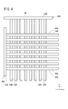
- FIG. 4 is a front view showing an example of the configuration of the first discharge electrode and the second discharge electrode of the discharge electrode portion.
- FIG. 5 is a schematic configuration view showing a processing apparatus (second processing apparatus) according to the second embodiment.
- FIG. 6 is a schematic configuration view showing the second processing apparatus as viewed from above.
- the processing apparatus includes a liquid reservoir 14 having a liquid to be treated 12 and a liquid 12 to be treated. And a bubble supply unit 20 for generating bubbles 18 containing the generated plasma on the liquid surface 12 a and supplying the bubbles 18 into the liquid 12 to be treated.
- the liquid to be treated 12 is adjusted to be acidic. For example, the pH is adjusted to be 4.8 or less. "On the liquid level 12a" means above the liquid level 12a or the liquid level 12a.
- the first processing apparatus 10A has, for example, a rectangular parallelepiped housing 22.
- the housing 22 has an upper surface 24a, a lower surface 24b, and four side surfaces (first side surface 26a to fourth side surface 26d), and faces, for example, the intake port 28 provided in the first side surface 26a and the first side surface 26a. And an exhaust port 30 provided in the second side surface 26b.
- the housing 22 is provided at the lower portion with the liquid storage unit 14 described above.
- a space 34 into which the gas 32 for generating plasma is introduced spreads on the liquid surface 12 a of the liquid 12 to be treated.
- the plasma generating gas 32 is supplied into the space 34 through the air inlet 28 and exhausted through the air outlet 30.
- a circulation flow path 36 for circulating the liquid to be treated 12 is provided on the side of the second side 26 b of the liquid storage portion 14 in the housing 22, for example.
- the circulation flow channel 36 has a liquid distribution unit 38 provided in the upper part of the housing 22 and a connection flow channel 40 connecting the liquid distribution unit 38 and the liquid storage unit 14.
- the connection channel 40 is piped via the outside of the second side surface 26 b of the housing 22.
- a pump (not shown) is used.
- the pump is not special, and a commonly used pumping pump can be used.
- the liquid to be treated 12 in the liquid storage portion 14 is pumped up to the liquid distribution portion 38 in the upper portion via the connection flow path 40, and the liquid to be treated 12 pumped up is again liquid reservoir. It is supplied to 14. That is, the liquid to be treated 12 is circulated to the liquid reservoir 14 through the circulation flow path 36.
- the area of the liquid distributor 38 is substantially the same as the area of the liquid reservoir 14.
- the bubble supply unit 20 is provided from the liquid distribution unit 38 of the circulation flow channel 36 toward the liquid storage unit 14.
- an aspirator 44 having a venturi unit 42 is preferably used as the bubble supply unit 20.
- the upper end 44 a of the aspirator 44 is connected to the liquid distribution unit 38, and the lower end 44 b is located on the liquid level 12 a of the liquid 12 to be treated. That is, the aspirator 44 is provided in a state of hanging down from the liquid distribution unit 38.
- a plurality of aspirators 44 are provided.
- FIG. 2 shows an example in which four pieces from the first side face 26a to the second side face 26b and four pieces from the third side face 26c to the fourth side face 26d, that is, a total of 16 pieces are installed.
- the plasma generating unit 16 is provided in the venturi unit 42 of each aspirator 44 respectively.
- the plasma generating unit 16 has, for example, a cylindrical case 46 provided in the venturi unit 42 and a discharge electrode unit 48 housed in the case 46.
- a portion where the discharge electrode portion 48 is installed is a plasma generation point 49.
- the case 46 has a gas inlet 50 for introducing the plasma generating gas 32 and a through hole 52 communicating with the venturi portion 42.
- the case 46 is in communication with the inside of the aspirator 44 through the through hole 52.
- the directions of the case 46 (the gas inlets 50) in each plasma generation unit 16 are all set to the same direction, but it is not necessary to limit to this. .
- the high voltage pulse is supplied to the discharge electrode unit 48 through the pulse power supply 54.
- the pulse power supply 54 may be provided for each of the plasma generation units 16 or one pulse power supply 54 common to the plurality of plasma generation units 16 may be provided. In FIG. 1 and FIG. 2, illustration of the pulse power source 54 is omitted.
- the discharge electrode unit 48 has a first discharge electrode 56A serving as an anode and a second discharge electrode 56B serving as a cathode.
- the first discharge electrode 56A and the second discharge electrode 56B are arranged separately from each other along the flow direction.
- the fluid flows in the direction in which the electric field generated between the first discharge electrode 56A and the second discharge electrode 56B becomes maximum, so that the generation efficiency of the active species can be improved.
- a multistage structure of three or more stages may be employed.
- the first discharge electrodes 56A extend in a first direction (x direction) and are arranged in a second direction (y direction) orthogonal to the first direction, and have a plurality of rod-like first conductors 58A, and a plurality of first conductors It has the 1st common conductor 60A which connects 58A, and the 1st ceramic layer 62A which covers at least the 1st conductor 58A.
- the second discharge electrode 56B extends in the second direction (y direction), and connects a plurality of rod-like second conductors 58B arranged in the first direction (x direction) and the plurality of second conductors 58B.
- first conductor 58A and the second conductor 58B Copper, iron, tungsten, stainless steel, platinum or the like can be used as the first conductor 58A and the second conductor 58B.
- first ceramic layer 62A and the second ceramic layer 62B alumina, silica, titania, zirconia or the like can be used.
- the pump is driven to circulate the liquid 12 to be treated.
- the pulse power supply 54 (see FIG. 3) is driven to generate plasma in each plasma generation unit 16.
- the gas 32 for plasma generation is supplied into the space 34 of the housing 22 through the inlet 28.
- the liquid to be treated 12 pumped up to the liquid distributor 38 in the upper part by the drive of the pump passes through the aspirator 44 of each bubble supply unit 20 and returns to the liquid reservoir 14. By repeating this operation, the liquid 12 to be treated is circulated.
- the flow rate is increased at the venturi portion 42, so that the pressure is lowered due to the venturi effect.
- the plasma generation gas 32 supplied to the space 34 is drawn into the plasma generation unit 16 and travels through the case 46 to the venturi unit 42.
- the plasma generated in the plasma generation part 16 flows into the venturi part 42 where the pressure is lowered together with the plasma generation gas 32, and the bubble 18 containing the plasma is generated in the liquid 12 to be treated which passes through the venturi part 42.
- the liquid to be treated 12 including the air bubbles 18 is returned to the liquid to be treated 12 in the liquid reservoir 14 through the aspirator 44.
- the plasma is generated on the liquid surface 12 a of the liquid to be treated 12, and the bubbles 18 containing the generated plasma are generated on the liquid surface 12 a and supplied into the liquid to be treated 12.
- the bubble 18 containing plasma can be supplied into the liquid 12 to be treated without immersing the treatment apparatus 10A itself in the liquid 12 to be treated.
- the number of first processing apparatuses 10A can be easily increased without being restricted by the volume of the container (in this case, the liquid storage portion 14) for containing the liquid 12 to be processed. It is possible to increase the concentration of the bubbles 18 supplied to the, that is, the amount (number) of bubbles per unit volume.
- the concentration of the bubbles 18 supplied to the liquid to be treated 12 It is possible to reduce the damage to the object to be treated.
- the dissolution rate of the gas in the bubble 18 supplied to the liquid to be treated 12 is improved, and the reaction product with the plasma active species or active species is It can be dissolved efficiently in it.
- the resistance (contact resistance) with the air bubble 18 is lowered, and the air bubble 18 becomes easy to move in the liquid 12 to be treated.
- the liquid to be treated 12 supplied to the liquid storage portion 14 the liquid to be treated 12 circulated and supplied from the liquid storage portion 14, that is, the liquid to be treated 12 to which the bubble 18 containing plasma is supplied is used. Therefore, the quantity (number) of bubbles 18 per unit volume can be increased, and the concentration (quantity per unit volume) of plasma active species dissolved in the liquid 12 to be treated or the reaction product with plasma active species can be increased. It can be enhanced.
- the microbubbles increase the contact area between the plasma active species or the reaction product with the plasma active species and the liquid 12 to be treated, and increase the internal pressure accompanying the miniaturization of the bubbles 18 and improve the solubility, so that the plasma active species or The reaction product with the plasma active species can be efficiently dissolved in the liquid 12 to be treated.
- most of the plasma generated in one plasma generation unit 16 can be introduced into the liquid to be processed 12 through the single bubble supply unit 20, so Many bubbles 18 can be generated.
- the first treatment apparatus 10A can also be configured as a sterilizer 70 that produces sterilizing water having a high sterilizing effect.
- FIG. 10B a processing apparatus according to the second embodiment (hereinafter referred to as a second processing apparatus 10B) will be described with reference to FIGS. 5 and 6.
- FIG. 10B a processing apparatus according to the second embodiment
- the second processing apparatus 10B has substantially the same configuration as the first processing apparatus 10A described above, but a combination of a plurality of bubble supply units 20 with one plasma generation unit 16 Are different in that they have at least one or more.
- a plurality of bubble supply units 20 are arranged circumferentially (circumferentially) around one plasma generation unit 16.
- the case 46 has a gas inlet 50 and guides the gas 32 for plasma generation to the plasma generation location 49, and plasma from the plasma generation location 49.
- a branch portion 68 for introducing a gas containing the above into each venturi portion 42 of the four bubble supply portions 20.
- the second processing apparatus 10B since the plasma generated by one plasma generation unit 16 can be introduced into the liquid to be processed 12 through the plurality of bubble supply units 20, the second processing apparatus 10B can It becomes possible to diffuse and supply many bubbles 18.
- the plasma generation unit 16 it is possible to distribute the plasma generated by one plasma generation unit 16 substantially equally to the plurality of bubble supply units 20 arranged on the circumference. That is, the plasma generation locations 49 for the plurality of bubble supply units 20 can be integrated into one. This leads to the reduction of the plasma generation point 49, and the second processing apparatus 10B can be simplified.
- the bubbles 18 generated in a large amount can be efficiently diffused to the liquid 12 to be treated, and the homogenization of, for example, the radical concentration in the liquid 12 to be treated can be rapidly advanced.
- the processing apparatus, the sterilizing apparatus, the sterilizing water, and the sterilizing method according to the present invention are not limited to the above-described embodiment, and it goes without saying that various configurations can be adopted without departing from the scope of the present invention.
Abstract
Description
Claims (14)
- 被処理液体(12)を有する液体貯溜部(14)と、
前記被処理液体(12)の液面(12a)上でプラズマを発生させるプラズマ発生部(16)と、
発生した前記プラズマを内包した気泡(18)を前記液面(12a)上で生成して前記被処理液体(12)中に供給する気泡供給部(20)と、を有する処理装置。 - 請求項1記載の処理装置において、
前記被処理液体(12)は酸性に調整されていることを特徴とする処理装置。 - 請求項1又は2記載の処理装置において、
前記気泡供給部(20)は、前記液体貯溜部(14)に供給する液体に前記プラズマ発生部(16)からの前記プラズマを導入することで前記気泡(18)を生成することを特徴とする処理装置。 - 請求項3記載の処理装置において、
前記気泡供給部(20)は、前記液体を前記液体貯溜部(14)に供給する流路途中にベンチュリー部(42)を具備したアスピレータ(44)を有し、前記プラズマ発生部(16)からの前記プラズマを前記ベンチュリー部(42)を介して導入することで、前記気泡(18)を生成することを特徴とする処理装置。 - 請求項3又は4記載の処理装置において、
前記被処理液体(12)の液面(12a)上にプラズマ発生用ガス(32)が導入される空間(34)を有し、
前記プラズマ発生部(16)及び前記気泡供給部(20)は前記空間(34)内に配され、
前記プラズマ発生部(16)は、前記空間(34)内への前記プラズマ発生用ガス(32)の導入に基づいてプラズマを発生させることを特徴とする処理装置。 - 請求項3~5のいずれか1項に記載の処理装置において、
前記液体は、前記液体貯溜部(14)から循環して供給された前記被処理液体(12)であることを特徴とする処理装置。 - 請求項1~6のいずれか1項に記載の処理装置において、
1つの前記プラズマ発生部(16)に対して1つの前記気泡供給部(20)の組み合わせが少なくとも1以上有することを特徴とする処理装置。 - 請求項1~6のいずれか1項に記載の処理装置において、
1つの前記プラズマ発生部(16)に対して複数の前記気泡供給部(20)の組み合わせが少なくとも1以上有することを特徴とする処理装置。 - 請求項8記載の処理装置において、
1つの前記プラズマ発生部(16)を中心に複数の前記気泡供給部(20)が円周上(円周状)に配列されていることを特徴とする処理装置。 - 被処理液体(12)を有する液体貯溜部(14)と、
前記被処理液体(12)の液面(12a)上でプラズマを発生させるプラズマ発生部(16)と、
発生した前記プラズマを内包した気泡(18)を前記液面(12a)上で生成して前記被処理液体(12)中に供給する気泡供給部(20)とを有することを特徴とする殺菌装置。 - 請求項10記載の殺菌装置において、
前記被処理液体(12)は酸性に調整されていることを特徴とする殺菌装置。 - 請求項10又は11記載の殺菌装置にて製造されたことを特徴とする殺菌水。
- 被処理液体(12)の液面(12a)上でプラズマを発生させ、
発生した前記プラズマを内包した気泡(18)を前記液面(12a)上で生成して前記被処理液体(12)中に供給することを特徴とする殺菌方法。 - 請求項13記載の殺菌方法において、
前記被処理液体(12)は酸性に調整されていることを特徴とする殺菌方法。
Priority Applications (3)
| Application Number | Priority Date | Filing Date | Title |
|---|---|---|---|
| JP2016538272A JPWO2016017456A1 (ja) | 2014-07-28 | 2015-07-17 | 処理装置、殺菌装置、殺菌水及び殺菌方法 |
| EP15826471.3A EP3176130A4 (en) | 2014-07-28 | 2015-07-17 | Treatment device, sterilization device, sterilization water, and sterilization method |
| US15/415,187 US20170128604A1 (en) | 2014-07-28 | 2017-01-25 | Treatment device, sterilization device, sterilization water, and sterilization method |
Applications Claiming Priority (2)
| Application Number | Priority Date | Filing Date | Title |
|---|---|---|---|
| US201462029703P | 2014-07-28 | 2014-07-28 | |
| US62/029,703 | 2014-07-28 |
Related Child Applications (1)
| Application Number | Title | Priority Date | Filing Date |
|---|---|---|---|
| US15/415,187 Continuation US20170128604A1 (en) | 2014-07-28 | 2017-01-25 | Treatment device, sterilization device, sterilization water, and sterilization method |
Publications (1)
| Publication Number | Publication Date |
|---|---|
| WO2016017456A1 true WO2016017456A1 (ja) | 2016-02-04 |
Family
ID=55217360
Family Applications (1)
| Application Number | Title | Priority Date | Filing Date |
|---|---|---|---|
| PCT/JP2015/070520 WO2016017456A1 (ja) | 2014-07-28 | 2015-07-17 | 処理装置、殺菌装置、殺菌水及び殺菌方法 |
Country Status (4)
| Country | Link |
|---|---|
| US (1) | US20170128604A1 (ja) |
| EP (1) | EP3176130A4 (ja) |
| JP (1) | JPWO2016017456A1 (ja) |
| WO (1) | WO2016017456A1 (ja) |
Cited By (5)
| Publication number | Priority date | Publication date | Assignee | Title |
|---|---|---|---|---|
| JP2016203082A (ja) * | 2015-04-21 | 2016-12-08 | 沖野 晃俊 | ラジカル機能液の製造方法およびラジカル機能液を用いた浄化方法 |
| EP3255961A1 (en) * | 2016-06-06 | 2017-12-13 | Amsalp Biomedical Co., Ltd. | Plasma liquid generating device |
| JP7034388B1 (ja) * | 2021-03-03 | 2022-03-11 | 三菱電機株式会社 | 活性粒子供給装置、およびそれを用いた水処理システム |
| US11492274B2 (en) | 2020-05-28 | 2022-11-08 | National Chiao Tung University | Liquid treatment apparatus |
| WO2023199604A1 (ja) * | 2022-04-13 | 2023-10-19 | 日本未来科学研究所合同会社 | 液体処理装置及び液体処理方法 |
Families Citing this family (3)
| Publication number | Priority date | Publication date | Assignee | Title |
|---|---|---|---|---|
| US10287152B2 (en) * | 2014-12-30 | 2019-05-14 | Gea Procomac S.P.A. | Apparatus and method for filling containers |
| CN107812217A (zh) * | 2017-11-20 | 2018-03-20 | 李厚兵 | 一种具有喷淋功能的灭菌柜 |
| CN108745012B (zh) * | 2018-06-14 | 2021-04-20 | 四川大学 | 一种可模块化组合的微型文丘里式气泡发生装置 |
Citations (3)
| Publication number | Priority date | Publication date | Assignee | Title |
|---|---|---|---|---|
| WO2009041049A1 (ja) * | 2007-09-27 | 2009-04-02 | Satoshi Ikawa | 殺菌方法および装置 |
| JP2012115777A (ja) * | 2010-12-01 | 2012-06-21 | Sharp Corp | 水中の殺菌方法、水中殺菌装置及びそれを用いた冷蔵庫 |
| JP2013129544A (ja) * | 2011-12-20 | 2013-07-04 | Asahi Organic Chemicals Industry Co Ltd | オゾン生成及びオゾン溶解装置 |
Family Cites Families (3)
| Publication number | Priority date | Publication date | Assignee | Title |
|---|---|---|---|---|
| US6723233B1 (en) * | 1999-09-10 | 2004-04-20 | Ronald L. Barnes | Ozone generator retrofit apparatus for jetted tubs and spas |
| US8764978B2 (en) * | 2001-07-16 | 2014-07-01 | Foret Plasma Labs, Llc | System for treating a substance with wave energy from an electrical arc and a second source |
| US20100240943A1 (en) * | 2009-03-19 | 2010-09-23 | Solnik Dvir | Degradation of organic pollutants in an aqueous environment using corona discharge |
-
2015
- 2015-07-17 WO PCT/JP2015/070520 patent/WO2016017456A1/ja active Application Filing
- 2015-07-17 EP EP15826471.3A patent/EP3176130A4/en not_active Withdrawn
- 2015-07-17 JP JP2016538272A patent/JPWO2016017456A1/ja not_active Abandoned
-
2017
- 2017-01-25 US US15/415,187 patent/US20170128604A1/en not_active Abandoned
Patent Citations (3)
| Publication number | Priority date | Publication date | Assignee | Title |
|---|---|---|---|---|
| WO2009041049A1 (ja) * | 2007-09-27 | 2009-04-02 | Satoshi Ikawa | 殺菌方法および装置 |
| JP2012115777A (ja) * | 2010-12-01 | 2012-06-21 | Sharp Corp | 水中の殺菌方法、水中殺菌装置及びそれを用いた冷蔵庫 |
| JP2013129544A (ja) * | 2011-12-20 | 2013-07-04 | Asahi Organic Chemicals Industry Co Ltd | オゾン生成及びオゾン溶解装置 |
Non-Patent Citations (1)
| Title |
|---|
| See also references of EP3176130A4 * |
Cited By (6)
| Publication number | Priority date | Publication date | Assignee | Title |
|---|---|---|---|---|
| JP2016203082A (ja) * | 2015-04-21 | 2016-12-08 | 沖野 晃俊 | ラジカル機能液の製造方法およびラジカル機能液を用いた浄化方法 |
| EP3255961A1 (en) * | 2016-06-06 | 2017-12-13 | Amsalp Biomedical Co., Ltd. | Plasma liquid generating device |
| US11492274B2 (en) | 2020-05-28 | 2022-11-08 | National Chiao Tung University | Liquid treatment apparatus |
| JP7034388B1 (ja) * | 2021-03-03 | 2022-03-11 | 三菱電機株式会社 | 活性粒子供給装置、およびそれを用いた水処理システム |
| WO2022185429A1 (ja) * | 2021-03-03 | 2022-09-09 | 三菱電機株式会社 | 活性粒子供給装置、およびそれを用いた水処理システム |
| WO2023199604A1 (ja) * | 2022-04-13 | 2023-10-19 | 日本未来科学研究所合同会社 | 液体処理装置及び液体処理方法 |
Also Published As
| Publication number | Publication date |
|---|---|
| JPWO2016017456A1 (ja) | 2017-04-27 |
| US20170128604A1 (en) | 2017-05-11 |
| EP3176130A4 (en) | 2018-01-10 |
| EP3176130A1 (en) | 2017-06-07 |
Similar Documents
| Publication | Publication Date | Title |
|---|---|---|
| WO2016017456A1 (ja) | 処理装置、殺菌装置、殺菌水及び殺菌方法 | |
| EP2036864A1 (en) | Water treatment apparatus | |
| KR102214680B1 (ko) | 활성화된 살균액 발생 장치 | |
| US6562386B2 (en) | Method and apparatus for non-thermal pasteurization | |
| JP6678338B2 (ja) | 液体処理装置 | |
| JP2015003297A (ja) | 排水液処理方法及び装置 | |
| CN103636294A (zh) | 等离子体生成方法及生成装置 | |
| CN114345154A (zh) | 等离子体活化水制备装置 | |
| KR20140066073A (ko) | 가압형 오존 용해 처리 장치 | |
| JP2014159008A (ja) | 水処理装置 | |
| JP2023500339A (ja) | オゾン処理水システムを備えた超音波スケーラ | |
| CN113242840A (zh) | 水处理装置和水处理方法 | |
| KR20190105643A (ko) | 음료수 생성 장치 | |
| CN108975446B (zh) | 液体处理装置 | |
| JP2017164260A (ja) | オゾン殺菌方法およびオゾン殺菌装置 | |
| US11242270B2 (en) | Portable water treatment system using ozone | |
| US20180344889A1 (en) | Space modification apparatus | |
| JP2012075347A (ja) | 水質制御装置、それを用いた植物栽培システム、及び植物栽培方法 | |
| JP2018196852A (ja) | 液体処理装置 | |
| KR20220031243A (ko) | 플라즈마 처리 시스템 및 이를 이용한 플라즈마수 제조 방법 | |
| JP5012638B2 (ja) | オゾン溶液の処理方法 | |
| JP2018164873A (ja) | 液体処理装置 | |
| KR102479272B1 (ko) | 플라즈마 방전수를 이용한 방역 시스템 및 플라즈마 방전수를 액적으로 분무하는 분무노즐 | |
| JP5929192B2 (ja) | 浄化装置及びそれを用いた水耕栽培システム | |
| JP5819135B2 (ja) | 水処理方法および水処理装置 |
Legal Events
| Date | Code | Title | Description |
|---|---|---|---|
| 121 | Ep: the epo has been informed by wipo that ep was designated in this application |
Ref document number: 15826471 Country of ref document: EP Kind code of ref document: A1 |
|
| ENP | Entry into the national phase |
Ref document number: 2016538272 Country of ref document: JP Kind code of ref document: A |
|
| REEP | Request for entry into the european phase |
Ref document number: 2015826471 Country of ref document: EP |
|
| WWE | Wipo information: entry into national phase |
Ref document number: 2015826471 Country of ref document: EP |
|
| NENP | Non-entry into the national phase |
Ref country code: DE |