WO2016017431A1 - 吸収性物品を製造する方法 - Google Patents
吸収性物品を製造する方法 Download PDFInfo
- Publication number
- WO2016017431A1 WO2016017431A1 PCT/JP2015/070320 JP2015070320W WO2016017431A1 WO 2016017431 A1 WO2016017431 A1 WO 2016017431A1 JP 2015070320 W JP2015070320 W JP 2015070320W WO 2016017431 A1 WO2016017431 A1 WO 2016017431A1
- Authority
- WO
- WIPO (PCT)
- Prior art keywords
- absorber
- absorbent article
- camera
- outer shape
- photographing
- Prior art date
- Legal status (The legal status is an assumption and is not a legal conclusion. Google has not performed a legal analysis and makes no representation as to the accuracy of the status listed.)
- Ceased
Links
Images


Classifications
-
- A—HUMAN NECESSITIES
- A61—MEDICAL OR VETERINARY SCIENCE; HYGIENE
- A61F—FILTERS IMPLANTABLE INTO BLOOD VESSELS; PROSTHESES; DEVICES PROVIDING PATENCY TO, OR PREVENTING COLLAPSING OF, TUBULAR STRUCTURES OF THE BODY, e.g. STENTS; ORTHOPAEDIC, NURSING OR CONTRACEPTIVE DEVICES; FOMENTATION; TREATMENT OR PROTECTION OF EYES OR EARS; BANDAGES, DRESSINGS OR ABSORBENT PADS; FIRST-AID KITS
- A61F13/00—Bandages or dressings; Absorbent pads
- A61F13/15—Absorbent pads, e.g. sanitary towels, swabs or tampons for external or internal application to the body; Supporting or fastening means therefor; Tampon applicators
-
- A—HUMAN NECESSITIES
- A61—MEDICAL OR VETERINARY SCIENCE; HYGIENE
- A61F—FILTERS IMPLANTABLE INTO BLOOD VESSELS; PROSTHESES; DEVICES PROVIDING PATENCY TO, OR PREVENTING COLLAPSING OF, TUBULAR STRUCTURES OF THE BODY, e.g. STENTS; ORTHOPAEDIC, NURSING OR CONTRACEPTIVE DEVICES; FOMENTATION; TREATMENT OR PROTECTION OF EYES OR EARS; BANDAGES, DRESSINGS OR ABSORBENT PADS; FIRST-AID KITS
- A61F13/00—Bandages or dressings; Absorbent pads
- A61F13/15—Absorbent pads, e.g. sanitary towels, swabs or tampons for external or internal application to the body; Supporting or fastening means therefor; Tampon applicators
- A61F13/45—Absorbent pads, e.g. sanitary towels, swabs or tampons for external or internal application to the body; Supporting or fastening means therefor; Tampon applicators characterised by the shape
- A61F13/49—Absorbent pads, e.g. sanitary towels, swabs or tampons for external or internal application to the body; Supporting or fastening means therefor; Tampon applicators characterised by the shape specially adapted to be worn around the waist, e.g. diapers, nappies
Definitions
- the present invention relates to a method for manufacturing an absorbent article, which includes at least an outline inspection step for inspecting the outline of an absorbent body of the absorbent article.
- Patent Document 1 a long continuous member used for an absorbent article is photographed for each predetermined photographing range using a camera (imaging device) while being transported, and the photographed image is displayed. Based on this, a method for manufacturing an absorbent article is disclosed in which an absorbent article having a pattern provided at a predetermined position is obtained by controlling the feeding speed of a continuous member.
- the outer shape of the absorber is not a simple rectangle for various reasons. Sometimes it is not.
- an absorbent body that extends from the wearer's stomach side to the back side through the crotch part has a shorter dimension in the short direction of the absorbent body because of the footstep in the portion covering the crotch part of the wearer.
- the absorbent body may include a portion in which the dimension in the short direction perpendicular to the longitudinal direction of the absorbent body varies along the longitudinal direction.
- the part where the dimensions change is not a simple shape such as a rectangle, so when shooting the absorber using the camera, the shooting area should be properly illuminated.
- the outer shape of the absorber cannot be accurately photographed.
- the manufactured absorbent article may not be determined to have an unacceptable outer shape in the inspection process even when an absorbent body whose outer shape is not acceptable is included.
- an absorbent article including an absorbent body that may not be able to sufficiently exhibit the expected performance will be shipped.
- an object of the present invention is to more accurately photograph the outer shape of the absorber including the portion in which the dimension in the short direction perpendicular to the longitudinal direction as described above changes along the longitudinal direction. It is an object of the present invention to provide a method for manufacturing an absorbent article, which can accurately determine whether or not it is acceptable.
- the present invention provides: A method of manufacturing an absorbent article using an absorbent body having a longitudinal direction and including a portion in which a dimension in a short direction perpendicular to the longitudinal direction varies along the longitudinal direction,
- each of the absorbers can be obtained by photographing the absorber continuously conveyed in the longitudinal direction on a conveyance path with a plurality of lights while photographing with a single camera.
- the outline inspection process includes A camera placement step of placing the one camera above the transport path at a distance that allows the entire length of the absorber to be copied in the short direction; An illumination arrangement step of arranging the plurality of illuminations on the upstream side and the downstream side in the conveying direction of the absorber, rather than the one camera, Using the one camera, photographing each of the absorbers, and obtaining a whole image of each absorber, An outer shape determination step for determining whether or not the outer shape of each absorber is acceptable from the image acquired in the photographing step; Including at least A method of manufacturing an absorbent article is provided.
- the present invention it is possible to more appropriately illuminate the contour of the absorber by arranging the plurality of illuminations on the upstream side and the downstream side in the conveying direction of the absorber, rather than one camera. Therefore, the outer shape of the absorber can be inspected more accurately. As a result, it is possible to manufacture an absorbent article including an absorber that can sufficiently exhibit the expected performance.
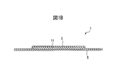
- FIG. 1B is a cross-sectional view taken along line IB-IB in FIG. 1A.
- the schematic side view of the external shape inspection unit which performs the external shape inspection process included in the manufacturing method which concerns on embodiment of this invention.
- the top view of the external form inspection unit of FIG. Schematic explaining a photographing process in time series. Schematic which shows the image acquired with the camera explaining the external shape determination process included in an external shape inspection process. Schematic explaining the fabric weight determination process included in the manufacturing method which concerns on embodiment of this invention.
- the manufactured absorbent article is the disposable diaper 1.
- the disposable diaper 1 manufactured by the method according to this embodiment has a liquid-permeable top sheet 3 positioned on the skin surface side of the wearer when worn and a non-skin surface side.
- a liquid-impervious back sheet 5 is provided, and a liquid-absorbing absorber 11 interposed between the top sheet 3 and the back sheet 5.
- the disposable diaper 1 can include an elastic member for tightening the wearer's leg and waist, an exterior sheet on which the design is printed, and the like.
- the method according to the present embodiment includes a step of forming the top sheet 3, the back sheet 5 and the absorbent body 11, respectively, and the top sheet 3, the back sheet 5 and the absorbent body 11 in the same manner as a conventional disposable diaper manufacturing method. And a step of bonding while aligning.
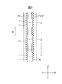
- the absorbent body 11 has an overall shape like an hourglass in a plan view when the disposable diaper 1 is deployed, and a longitudinal central portion 11LC that covers the wearer's crotch when worn is Compared with the longitudinal end portion 11LE, the dimension is smaller in the lateral direction. More specifically, the absorbent body 11 includes a portion 11LC having a longitudinal direction LD and a dimension of the short direction SD perpendicular to the longitudinal direction LD changing along the longitudinal direction LD.
- the method according to this embodiment is carried after the above-described step of forming the absorbent body 11 and before the step of bonding the absorbent body 11 while aligning with other members such as the top sheet 3.
- the outline inspection process is performed by the outline inspection unit 20.
- the outer shape inspection unit 20 includes a transport device 21 that transports the absorber 11, a single camera 23 that is installed above the transport device 21 and photographs the absorber 11, and the transport direction of the absorber 11 rather than the camera 23.
- a control device 27 that executes an outer shape determination step to be described later while controlling the above-described components of the outer shape inspection unit 20.
- the outer shape inspection unit 20 used for performing the outer shape inspection process will be described in more detail.
- the conveyed absorber 11 is covered with the conventional core wrap sheet
- the outer shape inspection step is a conveyance path TW formed on the outer surface of the suction conveyor 21 that can stably convey the absorbent body 11, which is the conveyance device of the present invention.
- the above is performed on the absorber 11 that is continuously conveyed in the longitudinal direction LD of the absorber 11.
- a rotary encoder 21 ⁇ / b> E is attached to the suction conveyor 21, and the distance that the absorber 11 is conveyed by the suction conveyor 21 can be detected.
- the conveyance distance detected by the rotary encoder 21E is transmitted to the control device 27 described later.
- the suction conveyor 21 includes a mesh belt 21B that forms a transport path TW on which the absorbent body 11 is placed and transported, and suction means 21M that sucks the absorbent body 11 through the mesh belt 21B.
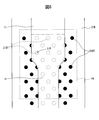
- the suction means 21M has an internal space connected to, for example, a vacuum pump or a blower, and has a plurality of through holes (not shown) for suction leading to the internal space in a portion facing the transport path TW. It is a suction box. As shown by black dots in FIG. 3, the mesh belt 21 ⁇ / b> B is formed with a through hole 21 ⁇ / b> BT that leads to the suction means 21 ⁇ / b> M and sucks the absorber 11.
- the camera 23 is an area camera that can acquire a rectangular image, and is at a distance from the transport path TW so as to capture at least the entire lateral direction SD of the absorber 11 transported on the transport path TW. It is arranged with. Particularly in the present embodiment, the camera 23 has a dimension of the imaging area PA to be imaged by the camera 23 that is half the length of the longitudinal direction LD of the absorber 11 (L / It is arranged at a distance from the absorber 11 so as to be larger than 2) and not to be able to copy the entire longitudinal direction LD of one absorber 11.
- two illuminations 25 for illuminating the imaging area PA are arranged on the transport path TW in the same manner as the camera 23.
- one illumination 25 ⁇ / b> U is disposed upstream of the camera 23 in the conveyance direction MD of the absorber 11, and the other illumination 25 ⁇ / b> D absorbs the camera 23. It arrange
- the illumination 25 is LED illumination.
- each illumination 25 has a bar shape, that is, a shape having a longitudinal direction in a direction orthogonal to the transport direction MD of the absorber 11, and in the transport direction MD of the absorber 11.
- the dimension in the orthogonal direction is larger than the dimension in the lateral direction SD of the absorbent body 11. Therefore, the absorber 11 can be illuminated by the illumination 25 over the entire short direction SD.
- the illumination 25 is provided at a position 200 mm from the absorber 11, and the illumination area 25 illuminates with an illuminance of about 4000 lux per illumination 25. At this time, the illuminance in the photographing area PA by one illumination 25 is preferably 2000 lux to 6000 lux.
- these illuminations 25 are controlled by the control device 27 so as to illuminate the imaging area PA with the above illuminance.
- the control device 27 is a PLC (programmable logic controller) having a CPU (microprocessor), a memory, an input port, an output port, and the like.
- the control device 27 is connected to each component of the contour inspection unit 20 in order to control the operation of the contour inspection unit 20, receives data from each component, and transmits a control signal to each component.
- the control device 27 receives data on the transport distance of the absorber 11 from the rotary encoder 21E, image data taken by the camera 23 from the camera 23, and the like. Then, the control device 27 transmits a control signal for instructing photographing timing to the camera 23, a control signal for adjusting illuminance to the illumination 25, and the like.
- the control apparatus 27 can determine whether the external shape of the absorber 11 is permissible based on the image image
- the outline inspection process includes the camera arrangement process for arranging the camera 23 as described above and the illumination arrangement process for arranging the illumination 25 as described above.
- the outer shape inspection process further includes an imaging process in which each absorber 11 is imaged using the camera 23 and an entire image of each absorber 11 is acquired.
- the control device 27 determines that the camera 23 has a length L per absorber 11 based on the transport distance of the absorber 11 transmitted from the rotary encoder 21E. As described above, a control signal for instructing the timing of shooting is transmitted to the camera 23 so that each half (L / 2) is taken. Therefore, the image is taken twice for each absorber 11, and as described above, the dimension in the longitudinal direction LD of the absorber 11 in the imaging region PA is half the length L per absorber 11 (L / 2), a part of the absorber 11 is photographed by overlapping the longitudinal direction LD of the absorber 11 in a plurality of images, so that the entire absorber 11 can be photographed. it can. And the control apparatus 27 acquires the image image
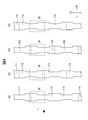
- FIG. 4 (a) to 4 (d) show the photographing steps in time series in order to assist understanding of the explanation of the photographing step described above, and the images are continuously conveyed when sequentially photographed by the camera 23.
- FIG. The state of the absorbers 111 to 114 being conveyed in the direction MD is shown.
- the absorber 111 is the absorber 11 located on the most downstream side
- the absorber 114 is the absorber 11 located on the most upstream side.
- FIG. 4 (a) images the downstream portion of the absorber 112
- FIG. 4 (b) images the upstream portion of the absorber 112
- FIG. 4 (c) illustrates the absorption.
- the downstream part of the body 113 is imaged
- FIG. 4D is an image of the upstream part of the absorber 114.
- the absorber 11 Since the absorber 11 is sequentially photographed as described above, in the present embodiment, a plurality of images of each absorber 11 acquired in the photographing process are photographed immediately before the first photographed image. It can be said that the image overlapped with the longitudinal direction LD of the absorber 11.
- the image taken in the state of FIG. 4B, in which the absorber 112 is photographed for the second time is photographed in the state of FIG. 4A, where the absorber 112 is photographed first.
- the image overlaps the longitudinal direction LD of the absorber 112.
- the outer shape inspection step further includes an outer shape determination step for determining whether or not the outer shape of each absorber 11 is acceptable from the image acquired in the shooting step, which is performed after the shooting step. Determination of the outer shape of each absorber 11 is performed using a virtual reference frame 31 set in advance in the imaging area PA as shown in FIG. The shape of the reference frame 31 is set so as to be separated from the contour of the desired absorber 11 by an allowable error.
- the reference frame 31 is smaller than the outer reference frame 31O for inspecting whether or not the outer shape of the absorber 11 is larger than an acceptable one, and the outer shape of the absorber 11 is smaller than an acceptable one.
- an inner reference frame 31I for inspecting whether or not it is present. That is, in the outer shape inspection process, when a part of the absorber 11 is contained in the outer reference frame 31O, the outer shape of the absorber 11 is unacceptable because the outer shape of the absorber 11 is larger than an acceptable one. Judged to be. Further, if there is a part of the inner reference frame 31I that does not contain the absorber 11, the outer shape of the absorber 11 is determined to be unacceptable because the outer shape of the absorber 11 is smaller than an acceptable one. Is done. As a result, not only the outer shape of the absorber 11 itself, but also the case where the absorber 11 is turned during transportation, torn due to the tension of transportation, or to be chipped is detected. Can do.
- the shape of the outer reference frame 31O for inspecting the outer shape of the longitudinal central portion 11LC whose dimensions in the short direction change along the longitudinal direction is the central portion of the absorbent body 11 in the longitudinal direction.
- the ellipse is adapted to the curvature of 11LC, and the shape of the other reference frame 31 is a rectangle.
- an arbitrary shape can be selected in consideration of the desired outer shape of the absorber 11 and an allowable error from the outer shape.
- the manufacturing method of the absorbent article according to the present embodiment further includes a discharging step of discharging the absorber 11 in which the outer shape is determined to be unacceptable among the absorbers 11 after the above-described outer shape inspection step.
- the discharging process is performed by a discharging device (not shown) provided in a subsequent process of the outer shape inspection unit 20.
- the discharging device is a device that excludes the absorber 11 having a defective outer shape, in which the outer shape of the absorber 11 in the control device 27 is unacceptable, from the conveyance path of the absorber 11.
- the discharge device is, for example, an air blow device that blows off a defective outer shape absorber with high-pressure air, or a pusher that pushes out a defective outer shape absorber from the side surface of the conveyance path.
- the discharge device is controlled by the control device 27 so that the absorber having a defective outer shape is discharged from the conveyance path of the absorber 11 when the absorber whose outer shape is determined to be unacceptable passes through the discharge device. It is controlled.
- the method for manufacturing an absorbent article according to the present embodiment includes a basis weight determination step of determining whether or not the absorbent body 11 includes a portion having a predetermined basis weight or less, in addition to the above-described outer shape inspection step.
- the basis weight determination step is performed based on the image acquired using the camera 23 in the above-described photographing step.
- the absorber 11 is conveyed on the mesh belt 21B, and the through-hole 21BT formed in the mesh belt 21B together with the absorber 11 is also photographed.
- the through hole 21BT appears to be black, and as a result, the absorber 11 has a lower basis weight than other parts and the through hole. If there is a portion 11F that overlaps with 21BT, the through hole 21BT may be seen through the absorber 11 in the portion 11F.
- an image including such a portion 11F is binarized (monochrome) using a predetermined threshold value such as luminance or brightness, and the image of the binarized absorber 11 is blackened.
- the absorbent body 11 By checking whether or not the portion 11F exists, it is possible to determine whether or not the absorbent body 11 includes a portion having a predetermined basis weight or less.
- a threshold value of values such as luminance and lightness when binarizing an image is determined according to a permissible basis weight that is required to be detected.
- the mesh belt 21B in which the through holes 21BT for sucking the absorber 11 are formed with a predetermined distribution is used in performing the basis weight determination process.
- another type of belt for example, A mesh mesh belt may be used.
- the manufacturing method of the absorbent article which concerns on this embodiment includes the external shape inspection process of the absorber 11, and this external shape inspection process is the upstream of the conveyance direction MD of the absorber 11 rather than the camera 23.
- positioning process which arrange
- each absorber 11 is photographed twice by the camera 23 so that the entire short direction SD of the absorber 11 is photographed.
- the whole of each absorber 11 is imaged.
- the outer shape of the longitudinal central portion 11C having a more complicated shape than a simple rectangle can be photographed more accurately, and more accurately whether or not the outer shape of the absorber 11 is acceptable. Judgment can be made.
- the two images of the respective absorbers 11 acquired in the imaging process overlap with the longitudinal direction LD of the absorber 11.
- the whole of each absorber 11 can be imaged, and as a result, the entire outer shape of each absorber 11 can be inspected without fail.
- the manufacturing method of the absorbent article according to the present embodiment includes a discharging step of discharging the absorber 11 that is determined to have an unacceptable outer shape after the outer shape inspection step.
- the method for manufacturing the absorbent article according to the present embodiment includes a weight determination step of determining whether or not the absorbent body 11 includes a portion having a predetermined basis weight or less. As a result, it is possible to detect the absorber 11 including a portion having a predetermined basis weight or less, and in the discharging step of discharging the absorber 11 including the portion having a predetermined basis weight or less, a portion having a predetermined basis weight or less is included. It can prevent shipping the absorbent article containing the absorber 11 as a product before the process of bonding with another member.
- the suction conveyor 21 is used as a transport device for transporting the absorbent body 11 in order to transport the absorbent body 11 stably.
- the absorber 11 being transported moves unintentionally due to vibrations of the transport device, etc., thereby preventing the position of the absorber 11 from deviating from the assumed location in the image acquired by the camera 23, As a result, the outer shape inspection of the absorber 11 can be performed stably.
- the optical axis OA of the illumination 25U arranged on the upstream side in the transport direction MD of the absorber 11 is tilted in the downstream direction in the transport direction MD of the absorber 11, and absorption is performed. It is preferable that the optical axis OA of the illumination 25D arranged on the downstream side in the transport direction MD of the body 11 is inclined in the upstream direction in the transport direction of the absorber. This is because the illumination 25U and 25D illuminate from both the upstream side and the downstream side toward the edge of the longitudinal center portion 11C of the absorbent body 11 where the short dimension SD of the absorbent body 11 is changing. This is because the outline of the absorber 11 can be taken clearly.
- the optical axis OA of the illumination 25 may not be inclined as shown in FIG. 2, and may extend directly below.
- the inclination angle ⁇ (FIG. 2) of the optical axis OA of the illumination 25 is 20 degrees to 40 degrees in order to capture a clear outline of the absorber 11.
- the “illumination optical axis” is a virtual light beam that is representative of the luminous flux emitted from the illumination 25, that is, emitted from the illumination starting from the central portion of the illuminated portion.
- An imaginary line extending in the direction in which the light beam travels shall be said.
- the optical axis OA of the illumination 25 when the optical axis OA of the illumination 25 is tilted as described above, the optical axis OA of the illumination 25U arranged on the upstream side in the transport direction MD of the absorber 11 and the transport direction of the absorber 11 More preferably, the optical axis OA of the illumination 25D disposed on the downstream side of the MD does not intersect the transport direction MD of the absorber 11 before reaching the absorber 11. If the optical axes OA of the illuminations 25U and 25D intersect in the transport direction MD of the absorber 11 before reaching the absorber 11, the light just below the camera 23, that is, in the central region of the imaging area PA.
- the optical axes OA (to each other) do not intersect in the transport direction MD of the absorber 11” specifically means that the optical axis OA of the illumination 25D located on the downstream side of the transport direction MD of the absorber 11 is.
- the point where the absorber 11 reaches the absorber 11 is more downstream than the point where the optical axis OA of the illumination 25U located on the upstream side in the transport direction MD of the absorber 11 reaches the absorber 11.
- the manufacturing method of the absorbent article according to the above-described embodiment includes a basis weight determining step of determining whether or not the absorbent body 11 includes a portion having a predetermined basis weight or less as described above. In another embodiment, only the outline inspection process is included, and the basis weight determination process is not included.
- the manufacturing method of the absorbent article which concerns on the above-mentioned embodiment WHEREIN:
- the absorber 11 in which the external shape was judged to be unacceptable among the absorber 11, and the absorber 11 containing a part below a predetermined basic weight from a conveyance path. Includes a discharging process.
- either one of the absorbent body 11 determined to have an unacceptable outer shape and the absorbent body 11 including a portion having a predetermined basis weight or less is discharged.
- the method for manufacturing an absorbent article does not include the discharging step.
- each absorber 11 is imaged twice using the camera 23.
- the resolution of the image acquired by the camera 23 is sufficiently high, the outer shape of the absorber 11 including the central portion 11LC in the longitudinal direction is obtained by an image acquired by capturing the entire absorber 11 only once.
- the inspection can be performed with sufficiently high accuracy.
- the camera 23 is placed at a distance from the transport path TW that can capture the entire length direction LD and width direction SD of one absorber 11, and photographing. In the process, each absorber 11 is photographed only once.
- each absorber 11 is imaged three or more times in the imaging process.
- the length of the imaging region PA in the longitudinal direction of the absorber 11 is larger than the length L of the longitudinal direction LD of the absorber 11 divided by the number of imaging per absorber 11, A plurality of images for each absorber 11 can be overlapped in the longitudinal direction LD of the absorber 11.
- each absorber 11 is overlapped in the longitudinal direction LD of the absorber 11 except for the first imaged image. be able to.
- the entire absorber 11 can be imaged, and as a result, the entire outer shape of each absorber 11 can be completely inspected.
- the length in the longitudinal direction LD of the absorber 11 in the imaging area PA may be the same as the length L obtained by dividing the length L in the longitudinal direction LD of the absorber 11 by the number of times of imaging per absorber 11.
- the suction conveyor 21 is used in the transport device that transports the absorbent body 11 in order to transport the absorbent body 11 stably.
- the transport device is not limited to the suction conveyor 21 as long as the absorber 11 can be transported stably.
- a normal belt conveyor may be used, or a driving nip roller that conveys the absorbent body 11 by rotating the absorbent body 11 before and after the region photographed by the camera 23 may be used.
- the illumination 25 has a bar shape, but the present invention is not limited to this shape.
- the illumination may be illumination of other shapes such as a donut shape or a panel (plate) shape as long as it can illuminate the photographing region evenly.
- the illumination 25 has a bar shape, since it can be illuminated uniformly with respect to the short direction SD of the absorber 11.
- the illumination 25 is LED illumination, but may be other types of light sources such as a fluorescent lamp and a mercury lamp. However, it is preferable that the LED illumination is less illuminance unevenness and a decrease in illuminance due to long-time use than that of other light sources, and it is not necessary to replace it more frequently.
- the outer shape inspection unit 20 is disposed on the downstream side of the illumination direction 25U disposed in the transport direction MD of the absorber 11 and the downstream side in the transport direction MD of the absorber 11 with respect to the camera 23.
- Two illuminations 25 are provided with the illumination 25D being provided.
- the outer shape inspection unit 20 transmits one or more illuminations other than these two illuminations upstream, downstream, Alternatively, both the upstream side and the downstream side may be provided.
- each component of the outer shape inspection unit 20 includes a control device separately. It may be. Further, the control device 27 may be automatically operated by a program created in advance, or may be manually operated with respect to some control such as adjustment of the illuminance of the illumination 25.
- control device 27 is a PLC, but it may be a computer or the like that can perform the same operation as the PLC.
- the manufactured absorbent article 1 was a disposable diaper.
- the absorbent article 1 manufactured by the method according to the present invention is another type of absorbent article including an absorbent body such as a sanitary napkin and a urine pad.
- the present invention is defined as follows.
- each of the absorbers can be obtained by photographing the absorber continuously conveyed in the longitudinal direction on a conveyance path with a plurality of lights while photographing with a single camera.
- the outline inspection process includes A camera placement step of placing the one camera above the transport path at a distance that allows the entire length of the absorber to be copied in the short direction; An illumination arrangement step of arranging the plurality of illuminations on the upstream side and the downstream side in the conveying direction of the absorber, rather than the one camera, Using the one camera, photographing each of the absorbers, and obtaining a whole image of each absorber, An outer shape determination step for determining whether or not the outer shape of each absorber is acceptable from the image acquired in the photographing step; Including at least A method of manufacturing an absorbent article.
- the one camera is further installed with a distance that cannot copy the entire longitudinal direction of the one absorber.
- photographing step photographing a plurality of times for each of the absorbers, The method to manufacture the absorbent article as described in ⁇ 1>.
- the respective absorbers are continuously photographed, A plurality of images of each of the absorbers acquired in the imaging step are overlapped in the longitudinal direction of the absorber with the image captured immediately before, except for the first captured image.
- the method to manufacture the absorbent article as described in ⁇ 2>.
- an optical axis of illumination arranged on the upstream side in the transport direction of the absorber is tilted in the downstream direction in the transport direction of the absorber
- the optical axis of illumination disposed on the downstream side in the transport direction of the absorber is inclined in the upstream direction in the transport direction of the absorber
- the optical axis of illumination arranged on the upstream side in the conveyance direction MD of the absorber and the optical axis of illumination arranged on the downstream side in the conveyance direction MD of the absorber are in the absorber. Do not intersect in the transport direction of the absorber before reaching The method to manufacture the absorbent article as described in ⁇ 4>.
- the inclination angles of the optical axes of the plurality of illuminations from the vertical direction are 20 degrees to 40 degrees, respectively.
- the plurality of lights are LED lights.
- the illuminance at a location where an image is acquired by the camera is 2000 lux to 6000 lux.
- Each of the plurality of lights has a shape having a longitudinal direction in a direction orthogonal to the transport direction, The dimension in the direction orthogonal to the transport direction of the plurality of illuminations is larger than the dimension in the short direction of the absorber.
- a discharge step of discharging the absorber, of which the outer shape is determined to be unacceptable is included.
- the basis weight determination step of determining whether or not the absorber includes a portion having a predetermined basis weight or less ⁇ 1> A method for producing the absorbent article according to any one of ⁇ 10>.
- a discharge step of discharging the absorber determined to include a portion having a predetermined basis weight or less is included.
Landscapes
- Health & Medical Sciences (AREA)
- Epidemiology (AREA)
- Engineering & Computer Science (AREA)
- Biomedical Technology (AREA)
- Heart & Thoracic Surgery (AREA)
- Vascular Medicine (AREA)
- Life Sciences & Earth Sciences (AREA)
- Animal Behavior & Ethology (AREA)
- General Health & Medical Sciences (AREA)
- Public Health (AREA)
- Veterinary Medicine (AREA)
- Absorbent Articles And Supports Therefor (AREA)
- Investigating Materials By The Use Of Optical Means Adapted For Particular Applications (AREA)
Abstract
本発明は吸収性物品(1)を製造する方法に関する。本発明に係る方法は、搬送路(TM)上を長手方向(LD)に連続的に搬送されている吸収体(11)を、複数の照明(25)で照らしつつ、1つのカメラ(23)によって撮影することにより、それぞれの吸収体の外形を検査する外形検査工程を含む。外形検査工程は、1つのカメラを、吸収体の短手方向(SD)の全体を写すことができる距離をもって、搬送路の上方に配置するカメラ配置工程と、複数の照明を、1つのカメラよりも、吸収体の搬送方向の上流側及び下流側にそれぞれ配置する照明配置工程と、1つのカメラを用いて、吸収体のそれぞれを撮影して、それぞれの吸収体の全体の画像を取得する撮影工程と、撮影工程において取得された画像から、それぞれの吸収体の外形が許容できるものか否か判断する外形判断工程とを少なくとも含む。
Description
本発明は、吸収性物品の吸収体の外形を検査する外形検査工程を少なくとも含む、吸収性物品を製造する方法に関する。
従来、吸収性物品の品質を向上させるために、使い捨てオムツや生理用ナプキン等の吸収性物品を製造する過程において、吸収性物品の半製品や最終製品の外形、あるいはこれらにプリントされた模様等の位置などを検査することが行われている。
例えば、特許文献1では、吸収性物品に使用される長尺状の連続部材を、搬送されているときにカメラ(撮像装置)を用いて所定の撮影範囲ごとに撮影し、撮影された画像に基づいて連続部材の繰り出し速度を制御することにより、模様が所定の位置に設けられた吸収性物品を得る、吸収性物品の製造方法が開示されている。
ところで、特許文献1に開示の発明のようにカメラを用いて、吸収性物品の製造中に、吸収体の外形を検査することを考えると、様々な理由から吸収体の外形は単純な矩形ではない場合もある。例えば、着用時において、着用者の腹側から股間部を通って背側まで延びる吸収体は、着用者の股間部を覆う部分において、足繰りのために吸収体の短手方向寸法が小さくなっている場合がある。つまり、当該吸収体は、吸収体の長手方向と直交する短手方向の寸法が長手方向に沿って変化する部分を含む場合がある。
カメラによる撮影環境によっては、このような寸法が変化している部分は、矩形のような単純な形状ではないことから、カメラを用いて吸収体を撮影するときに撮影領域を適切に照明することができず、ひいては、吸収体の外形を正確に撮影することができない場合がある。その結果、製造された吸収性物品は、外形が許容できない吸収体が含まれる場合であっても、検査工程において外形が許容できないと判断されない場合がある。その結果、期待される性能を十分に発揮することができないおそれのある吸収体を含む吸収性物品が出荷されてしまうおそれがある。
そこで、本発明の目的は、上述のような長手方向と直交する短手方向の寸法が長手方向に沿って変化する部分を含む吸収体の外形をより正確に撮影して、吸収体の外形が許容できるものであるか否かを正確に判断することのできる、吸収性物品を製造する方法を提供することにある。
上記目的を達成するために、本発明は、
長手方向を有し、かつ前記長手方向と直交する短手方向の寸法が前記長手方向に沿って変化する部分を含む吸収体を用いて吸収性物品を製造する方法であって、
前記吸収性物品を製造する方法は、搬送路上を前記長手方向に連続的に搬送されている前記吸収体を、複数の照明で照らしつつ、1つのカメラによって撮影することにより、それぞれの前記吸収体の外形を検査する外形検査工程を含み、
前記外形検査工程は、
前記1つのカメラを、前記吸収体の短手方向の全体を写すことができる距離をもって、前記搬送路の上方に配置するカメラ配置工程と、
前記複数の照明を、前記1つのカメラよりも、前記吸収体の搬送方向の上流側及び下流側にそれぞれ配置する照明配置工程と、
前記1つのカメラを用いて、前記吸収体のそれぞれを撮影して、それぞれの前記吸収体の全体の画像を取得する撮影工程と、
前記撮影工程において取得された画像から、それぞれの前記吸収体の外形が許容できるものか否か判断する外形判断工程と、
を少なくとも含む、
吸収性物品を製造する方法を提供する。
長手方向を有し、かつ前記長手方向と直交する短手方向の寸法が前記長手方向に沿って変化する部分を含む吸収体を用いて吸収性物品を製造する方法であって、
前記吸収性物品を製造する方法は、搬送路上を前記長手方向に連続的に搬送されている前記吸収体を、複数の照明で照らしつつ、1つのカメラによって撮影することにより、それぞれの前記吸収体の外形を検査する外形検査工程を含み、
前記外形検査工程は、
前記1つのカメラを、前記吸収体の短手方向の全体を写すことができる距離をもって、前記搬送路の上方に配置するカメラ配置工程と、
前記複数の照明を、前記1つのカメラよりも、前記吸収体の搬送方向の上流側及び下流側にそれぞれ配置する照明配置工程と、
前記1つのカメラを用いて、前記吸収体のそれぞれを撮影して、それぞれの前記吸収体の全体の画像を取得する撮影工程と、
前記撮影工程において取得された画像から、それぞれの前記吸収体の外形が許容できるものか否か判断する外形判断工程と、
を少なくとも含む、
吸収性物品を製造する方法を提供する。
本発明によれば、複数の照明が、1つのカメラよりも、吸収体の搬送方向の上流方向側及び下流方向側にそれぞれ配置されたことにより、吸収体の輪郭線をより適切に照明することができるので、吸収体の外形をより正確に検査することができる。その結果、期待された性能を十分に発揮することのできる吸収体を含む吸収性物品を製造することができる。
本発明は上述の図面を参照しつつより詳細に記載される。なお、これらの図面は、本発明の理解を容易にすると共に図面の記載を簡略化するために、実際の構成要素の大きさ、縮尺、形状と同一に描かれていない場合があることに留意されたい。
これより、本発明の実施形態に係る吸収性物品を製造する方法について、図面を参照しつつ説明する。本実施形態に係る方法では、製造される吸収性物品は使い捨てオムツ1である。
図1A及び図1Bに示すように、本実施形態に係る方法によって製造される使い捨てオムツ1は、着用時に着用者の肌面側に位置する液透過性のトップシート3と、非肌面側に位置する不透液性のバックシート5と、これらトップシート3及びバックシート5の間に介在する吸液性の吸収体11とを備える。使い捨てオムツ1は、これらの他にも、着用者の脚回り及び胴回りを締め付けるための弾性部材や、デザインがプリントされた外装シートなどを備えることができる。
本実施形態に係る方法は、従来の使い捨てオムツの製造方法と同様に、トップシート3、バックシート5及び吸収体11をそれぞれ形成する工程と、これらトップシート3、バックシート5及び吸収体11を位置合わせしつつ貼り合わせる工程とを含む。
図1Aに示すように、吸収体11は、使い捨てオムツ1の展開時に、平面視において全体的に砂時計のような外形を有しており、着用時に着用者の股間を覆う長手方向中央部11LCは、長手方向端部11LEと比較すると、短手方向に寸法が小さくなっている。より具体的には、吸収体11は、長手方向LDを有し、かつ長手方向LDと直交する短手方向SDの寸法が長手方向LDに沿って変化する部分11LCを含む。
本実施形態に係る方法は、上述の、吸収体11を形成する工程の後であって、吸収体11をトップシート3などの他の部材と位置合わせしつつ貼り合わせる工程の前に、搬送されている吸収体11に対して適切に照明しつつ撮影された吸収体11の画像から、吸収体11の外形が許容できるものか否かを判断するための外形検査工程を含む。
外形検査工程は、外形検査ユニット20によって行われる。外形検査ユニット20は、吸収体11を搬送する搬送装置21と、搬送装置21の上方に設置された、吸収体11を撮影する1つのカメラ23と、カメラ23よりも、吸収体11の搬送方向の上流側及び下流側に配置される複数の照明25と、外形検査ユニット20の上記構成要素を制御しつつ後述する外形判断工程を実行する制御装置27とを備える。
これより、外形検査工程を行うのに使用される外形検査ユニット20についてより詳細に説明する。なお、本実施形態では、搬送されている吸収体11は、吸収体11の保形性を確保するために、繊維不織布やティッシュシートなどからなる従来のコアラップシートで覆われているが、このコアラップシートは図示されていない点に留意されたい。
外形検査工程は、図2及び図3に示すように、本発明の搬送装置である、吸収体11を安定して搬送することのできるサクションコンベア21の外表面上に形成されている搬送路TW上を、吸収体11の長手方向LDに連続的に搬送されている吸収体11に対して行われる。サクションコンベア21には、ロータリエンコーダ21Eが付設されており、サクションコンベア21によって吸収体11が搬送された距離を検知することができる。ロータリエンコーダ21Eによって検出された搬送距離は、後述する制御装置27に送信される。
サクションコンベア21は、吸収体11を載置して搬送するための搬送路TWを形成するメッシュベルト21Bと、メッシュベルト21Bを通して吸収体11を吸引するサクション手段21Mとを備える。サクション手段21Mは例えば、真空ポンプやブロワなどと接続されている内部空間を有し、搬送路TWに対向する部分に、上記内部空間に通じる吸引のための複数の貫通孔(図示しない)を有するサクションボックスである。図3において黒点で示すように、メッシュベルト21Bには、サクション手段21Mに通じる、吸収体11を吸引するための貫通孔21BTが形成されている。
カメラ23は、矩形の画像を取得することのできるエリアカメラであって、搬送路TW上で搬送されている吸収体11の短手方向SDの全体を少なくとも撮影できるように、搬送路TWから距離をもって配置される。本実施形態では特に、カメラ23は、カメラ23によって撮影されることになる撮影領域PAの寸法が、吸収体11の長手方向LDにおいて、吸収体11の長手方向LDの長さの半分(L/2)よりも大きくなるようにかつ1つの吸収体11の長手方向LDの全体を写すことのできないように、吸収体11からの距離をもって配置されている。
撮影領域PAを照明するための、本実施形態では2つの照明25が、カメラ23と同様に搬送路TW上に配置される。これら2つの照明25のうちの、一方の照明25Uは、カメラ23に対して、吸収体11の搬送方向MDの上流側に配置されており、他方の照明25Dは、カメラ23に対して、吸収体11の搬送方向MDの下流側に配置されている。本実施形態では、照明25は、LED照明である。
また、本実施形態では、照明25はそれぞれ、バー形状を有しており、すなわち、吸収体11の搬送方向MDに直交する方向に長手方向を有する形状であり、吸収体11の搬送方向MDに直交する方向の寸法が、吸収体11の短手方向SDの寸法よりも大きい。したがって、照明25によって、吸収体11を短手方向SDの全体にわたって照明することができる。さらに、照明25は、本実施形態では吸収体11から200mmの位置に設けられており、撮影領域PAにおいて、1つの照明25につき約4000ルクスの照度で照明している。このとき、1つの照明25による、撮影領域PAにおける照度は、2000ルクス~6000ルクスであると好ましい。照度が2000ルクス以上であることによって、撮影領域PAにおいて吸収体11の外形をはっきりと撮影できる程度に照明することができる。その一方で、照度が6000ルクス以下であることによって、吸収体11の輪郭線が白飛びすることにより吸収体11の輪郭線を認識できくなることを防ぐことができる。なお、本実施形態では、これらの照明25は、上述の照度をもって撮影領域PAを照明するように制御装置27によって制御されている。
制御装置27は、CPU(マイクロプロセッサ)、メモリ、入力ポート、出力ポートなどを備えたPLC(プログラマブルロジックコントローラ)である。制御装置27は、外形検査ユニット20の動作を制御するために外形検査ユニット20の各構成要素に接続されており、各構成要素からデータを受信しかつ各構成要素に制御信号を送信する。具体的には、本実施形態では、制御装置27は、ロータリエンコーダ21Eから吸収体11の搬送距離のデータ、カメラ23からカメラ23によって撮影された画像データなどを受信する。そして、制御装置27は、カメラ23に撮影タイミング指示の制御信号、照明25に照度調節の制御信号などを送信する。また、制御装置27は、後述する外形判断工程により、カメラ23によって撮影された画像に基づいて、吸収体11の外形が許容できるものか否かを判断することができる。
これより、それぞれの吸収体11の外形を検査する外形検査工程について詳細に説明する。外形検査工程は、上述のようにカメラ23を配置するカメラ配置工程と、上述のように照明25を配置する照明配置工程とを含む。
外形検査工程はさらに、カメラ23を用いてそれぞれの吸収体11を撮影して、それぞれの吸収体11の全体の画像を取得する撮影工程を含む。
撮影工程を実行するために、制御装置27は、カメラ23が、ロータリエンコーダ21Eからの送信される吸収体11の搬送距離に基づいて、吸収体11が吸収体11一つあたりの長さLの半分(L/2)だけ搬送されるごとに撮影するように、上述のようにカメラ23に撮影するタイミングを指示する制御信号を送信する。よって、1つの吸収体11あたり2回撮影するようにされており、上述のように撮影領域PAの吸収体11の長手方向LDの寸法が吸収体11一つあたりの長さLの半分(L/2)よりも大きいので、吸収体11の一部が複数の画像において、吸収体11の長手方向LDにオーバーラップして撮影されることにより、それぞれの吸収体11の全体を撮影することができる。そして、制御装置27は、カメラ23によって撮影された画像を取得する。
図4(a)~(d)は、上述の撮影工程の説明の理解を補助するために撮影工程を時系列で示すものであって、カメラ23によって逐次撮影されるときの、連続的に搬送方向MDに搬送されている吸収体111~114の状態を示すものである。なお、吸収体111~114のうちで、吸収体111は最も下流に位置している吸収体11であり、吸収体114は最も上流に位置する吸収体11である。具体的には、図4(a)は吸収体112の下流側部分を撮影しており、図4(b)は吸収体112の上流側部分を撮影しており、図4(c)は吸収体113の下流側部分を撮影しており、そして図4(d)は吸収体114の上流側部分を撮影している。
上述のように吸収体11を逐次撮影することから、本実施形態では、撮影工程で取得された、それぞれの吸収体11の複数の画像はそれぞれ、最初に撮影した画像を除いて、直前に撮影した画像と吸収体11の長手方向LDにオーバーラップしているということができる。具体的な例を挙げると、吸収体112を2回目に撮影する、図4(b)の状態で撮影した画像は、吸収体112を最初に撮影する、図4(a)の状態で撮影した画像と、吸収体112の長手方向LDにオーバーラップしている。また、これと同様のことが、吸収体113について、図4(c)及び図4(d)の状態で撮影した画像について当てはまる。
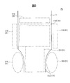
外形検査工程はさらに、上記撮影工程の後に行われる、撮影工程において取得された画像から、それぞれの吸収体11の外形が許容できるものか否か判断する外形判断工程を含む。それぞれの吸収体11の外形の判断は、図5に示されているような、撮影領域PA内に予め設定された仮想の基準枠31を用いて行われる。基準枠31は、所望の吸収体11の輪郭線から許容可能な誤差だけ離間するように、形状が設定されている。
具体的には、基準枠31は、吸収体11の外形が許容できるものよりも大きくなっていないかを検査するための外側基準枠31Oと、吸収体11の外形が許容できるものよりも小さくなっていないかを検査するための内側基準枠31Iとを含む。つまり、外形検査工程では、外側基準枠31O内に吸収体11の一部が入っている場合には、吸収体11の外形が許容できるものよりも大きいとして、当該吸収体11の外形は許容できないものと判断される。また、内側基準枠31I内に一部でも吸収体11が入っていない部分がある場合は、吸収体11の外形が許容できるものよりも小さいとして、当該吸収体11の外形は許容できないものと判断される。これによって、吸収体11自体の外形だけではなく、吸収体11が搬送中にめくれてしまったり、搬送の張力によって裂けてしまったり、あるいは欠けてしまったりしたような場合も、これらを検出することができる。
本実施形態では、基準枠31は、短手方向の寸法が前記長手方向に沿って変化する長手方向中央部11LCの外形を検査する外側基準枠31Oの形状は、吸収体11の長手方向中央部11LCの曲率に適合した楕円形になっており、その他の基準枠31の形状は矩形になっている。これら基準枠31のそれぞれの形状は、所望の吸収体11の外形及び当該外形からの許容可能な誤差を考慮して、任意の形状を選択することができる。
本実施形態に係る吸収性物品の製造方法はさらに、上述の外形検査工程後に、吸収体11のうちの、外形が許容できないと判断された吸収体11を排出する排出工程を含む。
排出工程は、外形検査ユニット20の後工程に設けられた排出装置(図示しない)によって行われる。排出装置は、制御装置27における吸収体11の外形が許容できないと判断された外形不良の吸収体11を、吸収体11の搬送路から排除する装置である。排出装置は、例えば、高圧の空気で外形不良の吸収体を吹き飛ばすエアブロー装置や、搬送路の側面から外形不良の吸収体を押し出すプッシャなどである。本実施形態では、排出装置は、外形が許容できないと判断された吸収体が排出装置を通過するときに、外形不良の吸収体を吸収体11の搬送路から排出するように、制御装置27によって制御されている。
本実施形態に係る吸収性物品を製造する方法は、上述の外形検査工程に加えて、さらに吸収体11が所定の坪量以下の部分を含むか否かを判断する目付け判断工程を含む。目付け判断工程は、次に述べるように、上述の撮影工程においてカメラ23を用いて取得された画像に基づいて行われる。
撮影工程では、吸収体11は、メッシュベルト21B上で搬送されており、吸収体11と一緒にメッシュベルト21Bに形成されている貫通孔21BTも一緒に撮影されることになる。このとき、カメラ23で取得された画像では、図6に示すように、貫通孔21BTは黒色で写ることになり、その結果、吸収体11に、坪量がその他の部分よりも低くかつ貫通孔21BTと重なっている部分11Fが存在すると、当該部分11Fにおいて貫通孔21BTが吸収体11を透けて写る場合がある。目付け判断工程では、このような部分11Fを含む画像を、例えば、輝度や明度などの値の所定の閾値によって二値化(モノクロ化)して、二値化した吸収体11の画像に黒色の部分11Fが存在するか否かを確認することによって、吸収体11が所定の坪量以下の部分を含むか否かを判断することができる。この場合において、画像を二値化するときの輝度や明度などの値の閾値は、検出することが求められる坪量の許容値に応じて決まる。
なお、目付け判断工程を実行するにあたり、本実施形態では、吸収体11を吸引するための貫通孔21BTが所定の分布をもって形成されているメッシュベルト21Bを用いたが、別のタイプのベルト、例えば網状のメッシュベルトを用いてもよい。
これより、本実施形態に係る方法の作用効果について説明する。
(1) 本実施形態に係る吸収性物品の製造方法は、吸収体11の外形検査工程を含んでおり、この外形検査工程は、カメラ23よりも、吸収体11の搬送方向MDの上流側と下流側との両方に照明25を配置する照明配置工程を含んでいる。それにより、吸収体11の搬送方向MDの上流側及び下流側の両方から撮影領域PAを照明することによって、吸収体11の輪郭線をより適切に照明することができるので、吸収体11の、特に短手方向SDの寸法が長手方向LDに沿って変化している長手方向中央部11LCの輪郭線をより鮮明に撮影することができる。その結果、より正確に当該部分11LCの外形を撮影することができ、ひいてはより正確に吸収体11の外形が許容できるものか否か判断することができる。
(2) 本実施形態では、撮影工程において、上述のように、それぞれの吸収体11は、吸収体11の短手方向SDの全体が撮影されるようにカメラ23によって2回撮影することによって、それぞれの吸収体11の全体が撮影される。それにより、カメラ23を吸収体11からさらに離して配置して、吸収体11の全体を1回のみで撮影することと比較すると、吸収体11をより大きく撮影することができる。したがって、カメラ23の解像度に限界がある場合においても、撮影領域PAの縦横方向を横断するように延びている長手方向中央部11LCの輪郭線をより滑らかに、ひいては正確に撮影できるので好ましい。その結果、単純な矩形よりも複雑な形状を有する長手方向中央部11Cに関しても、外形をより正確に撮影することができ、ひいては、吸収体11の外形が許容できるものか否かをより正確に判断することができる。
(3) 本実施形態では、上述のように、撮影工程で取得したそれぞれの吸収体11の2つの画像は、吸収体11の長手方向LDにオーバーラップしている。その結果、それぞれの吸収体11の全体を撮影することができ、ひいては、それぞれの吸収体11の全体の外形をもれなく検査することができる。
(4) 本実施形態に係る吸収性物品の製造方法は、外形検査工程後に、吸収体11のうちの、外形が許容できないと判断された吸収体11を排出する排出工程を含む。その結果、外形が許容できないと判断された吸収体11を含む吸収性物品を製品として出荷してしまうことを、他の部材と貼り合わせる工程の前に防ぐことができる。
(5) 本実施形態に係る吸収性物品を製造する方法は、吸収体11が所定の坪量以下の部分を含むか否かを判断する目付け判断工程を含む。その結果、所定の坪量以下の部分を含む吸収体11を検出することができ、所定の坪量以下の部分を含む吸収体11を排出する排出工程において、所定の坪量以下の部分を含む吸収体11含む吸収性物品を製品として出荷してしまうことを、他の部材と貼り合わせる工程の前に防ぐことができる。
(6) 本実施形態では、吸収体11を安定して搬送するために、吸収体11を搬送する搬送装置にサクションコンベア21を用いた。これにより、搬送中の吸収体11が搬送装置の振動などによって意図しないように動くことによって、カメラ23によって取得した画像において、吸収体11の位置が想定された場所からずれてしまうことを防ぎ、ひいては吸収体11の外形検査を安定して行うことができる。
また、図2に示すように、吸収体11の搬送方向MDの上流方向側に配置されている照明25Uの光軸OAが、吸収体11の搬送方向MDの下流方向に傾けられており、吸収体11の搬送方向MDの下流方向側に配置されている照明25Dの光軸OAは吸収体の搬送方向の上流方向に傾けられていると好ましい。これは、吸収体11の短手方向SD寸法が変化している吸収体11の長手方向中央部11Cの縁部に向かって、照明25U、25Dにより上流側及び下流側の両方から照明することができ、ひいては、吸収体11の輪郭線を鮮明に撮影することができるからである。しかしながら、照明25の構造による光束の拡がりによっては、上述のように照明25の光束を傾けなくてもカメラ23の下を適切に照明することができる場合もある。したがって、照明25の光軸OAは、図2に示すように傾けられていなくてもよく、真下に延びていてもよい。
また同様に、吸収体11の輪郭線を鮮明に撮影するために、照明25の光軸OAの鉛直方向からの傾斜角度α(図2)が、20度~40度であるとさらに好ましい。
なお、本発明において「照明の光軸」とは、照明25から照射される光束の代表となる仮想的な光線であり、すなわち、照明の照射部分の中央部分を始点として、照明から照射される光束が進行する方向に延びる仮想線をいうものとする。
また、照明25の光軸OAが上述のように傾けられているときに、吸収体11の搬送方向MDの上流方向側に配置されている照明25Uの光軸OAと、吸収体11の搬送方向MDの下流方向側に配置されている照明25Dの光軸OAとは、吸収体11に到達する前に、吸収体11の搬送方向MDにおいて交差しないとさらに好ましい。これは、これら照明25U、25Dの光軸OAが、吸収体11に到達する前に、吸収体11の搬送方向MDにおいて交差してしまうと、カメラ23の真下、つまり撮影領域PAの中央領域において光量が他の領域よりも大きくなってしまい、撮影領域PAを均等に照明することができず、また吸収体11の輪郭線を鮮明に撮影することができないおそれがあるからである。なお、「光軸OA(同士)が吸収体11の搬送方向MDにおいて交差しない」とは、具体的には、吸収体11の搬送方向MDの下流方向側に位置する照明25Dの光軸OAが吸収体11に到達する地点が、吸収体11の搬送方向MDの上流方向側に位置する照明25Uの光軸OAが吸収体11に到達する地点よりも、吸収体11の搬送方向MDの下流側に位置することを意味する。その逆に、上流方向側に位置する照明25Uの光軸OAについてもまた同様である。
上述の実施形態に係る吸収性物品の製造方法は、上述のように吸収体11が所定の坪量以下の部分を含むか否かを判断する目付け判断工程を含む。別の実施形態では、外形検査工程のみを含み、目付け判断工程を含まない。
上述の実施形態に係る吸収性物品の製造方法は、吸収体11のうちの、外形が許容できないと判断された吸収体11と所定の坪量以下の部分を含む吸収体11とを搬送路から排出する排出工程を含む。別の実施形態の排出工程では、吸収体11のうちの、外形が許容できないと判断された吸収体11及び所定の坪量以下の部分を含む吸収体11のいずれか一方を排出する。さらに別の実施形態では、吸収性物品の製造方法は、当該排出工程を含まない。
上述の実施形態では、カメラ23を用いて、それぞれの吸収体11について2回撮影する。しかしながら、カメラ23によって取得される画像の解像度が十分に高ければ、それぞれの吸収体11の全体を1回のみの撮影によって取得した画像によって、吸収体11の外形を、長手方向中央部11LCを含めて、十分に高い精度で検査することができる。この場合では、別の実施形態として、カメラ配置工程において、カメラ23を搬送路TWから1つの吸収体11の長手方向LD及び短手方向SDの全体を写すことのできる距離をもって配置して、撮影工程において、それぞれの吸収体11について1回のみ撮影する。
また、さらに別の実施形態では、撮影工程において、それぞれの吸収体11について3回以上撮影する。このようにすることによって、一定の解像度において、それぞれの吸収体11について2回撮影する場合と比較して、吸収体11の外形を、特に吸収体11の長手方向中央部11LCの境界線を、より大きく、ひいては鮮明に撮影することができる。また、この場合、吸収体11の長手方向について撮影領域PAの長さが、吸収体11の長手方向LDの長さLを1つの吸収体11あたりの撮影回数で割った長さよりも大きいと、それぞれの吸収体11についての複数の画像を、吸収体11の長手方向LDにオーバーラップさせることができる。つまり、上述の実施形態と同様に、それぞれの吸収体11の3つ以上の画像をそれぞれ、最初に撮影した画像を除いて、直前に撮影した画像と吸収体11の長手方向LDにオーバーラップさせることができる。その結果、それぞれの吸収体11の全体を撮影することができ、ひいてはそれぞれの吸収体11の全体の外形をもれなく検査することができるので好ましい。しかしながら、撮影領域PAの吸収体11の長手方向LDの長さは、吸収体11の長手方向LDの長さLを1つの吸収体11あたりの撮影回数で割った長さと同じでもよい。
上述の実施形態では、吸収体11を安定して搬送するために、吸収体11を搬送する搬送装置にサクションコンベア21を用いた。しかしながら、吸収体11を安定して搬送することができるのであれば、搬送装置は、サクションコンベア21に限らない。例えば、通常のベルトコンベアでもよく、あるいはカメラ23によって撮影する領域の前後で吸収体11を挟みつつ回転駆動することによって吸収体11を搬送する駆動ニップローラでもよい。
上述の実施形態では、照明25はバー形状を有しているが、本発明はこの形状に限定されない。例えば、照明は、撮影領域を均等に照明することのできるものであれば、ドーナツ形状、パネル(板)形状などの他の形状の照明であってもよい。しかしながら、照明25がバー形状であると、吸収体11の短手方向SDに関して、均等に照明できるので好ましい。
また、上述の実施形態では、照明25はLED照明であるが、蛍光灯、水銀灯などの他タイプの光源であってもよい。しかしながら、LED照明であると、他の光源に比べて、照度ムラや長時間使用による照度の低下が少なく、さらに頻繁に交換する必要がないので好ましい。
さらに、上述の実施形態では、外形検査ユニット20は、カメラ23よりも、吸収体11の搬送方向MDの上流側に配置されている照明25Uと、吸収体11の搬送方向MDの下流側に配置されている照明25Dとの2つの照明25を備える。しかしながら、外形検査ユニット20は、撮影領域PAの光量を増加しかつ/又は光量を均等にするために、これら2つの照明以外の1又は複数の照明を、カメラ23よりも上流側、下流側、又は上流側及び下流側の両方に備えていてもよい。
また、上述の実施形態では、カメラ23や照明25などの外形検査ユニット20の構成要素が1つの制御装置27によって制御されているが、外形検査ユニット20の構成要素はそれぞれ別個に制御装置を備えていてもよい。また、制御装置27は予め作成したプログラムによって自動で作動するようにしてもよいし、照明25の照度の調節などの一部の制御に関しては手動で操作してもよい。
上述の実施形態では、制御装置27は、PLCであったが、PLCと同様の動作をすることのできるコンピュータなどであってもよい。
上述の実施形態では、製造される吸収性物品1は使い捨てオムツであった。別の実施形態では、本発明に係る方法によって製造される吸収性物品1は、生理用ナプキン、尿取りパットなどの吸収体を含む他の種類の吸収性物品である。
本明細書、図面及び特許請求の範囲の記載から当業者によって理解できるような全ての特徴は、本明細書において、これらの特徴が特定の他の特徴に関連してのみ組み合わされて説明されたとしても、それらの特徴が明確に除外されない限り、又は技術的な態様が不可能な若しくは意味のない組み合わせにならない限りにおいて、独立して、またさらに、ここで開示された他の1又は複数の特徴と任意に組み合わせて、結合することができるものとする。
本発明は、以下のように規定される。
<1> 長手方向を有し、かつ前記長手方向と直交する短手方向の寸法が前記長手方向に沿って変化する部分を含む吸収体を用いて吸収性物品を製造する方法であって、
前記吸収性物品を製造する方法は、搬送路上を前記長手方向に連続的に搬送されている前記吸収体を、複数の照明で照らしつつ、1つのカメラによって撮影することにより、それぞれの前記吸収体の外形を検査する外形検査工程を含み、
前記外形検査工程は、
前記1つのカメラを、前記吸収体の短手方向の全体を写すことができる距離をもって、前記搬送路の上方に配置するカメラ配置工程と、
前記複数の照明を、前記1つのカメラよりも、前記吸収体の搬送方向の上流側及び下流側にそれぞれ配置する照明配置工程と、
前記1つのカメラを用いて、前記吸収体のそれぞれを撮影して、それぞれの前記吸収体の全体の画像を取得する撮影工程と、
前記撮影工程において取得された画像から、それぞれの前記吸収体の外形が許容できるものか否か判断する外形判断工程と、
を少なくとも含む、
吸収性物品を製造する方法。
前記吸収性物品を製造する方法は、搬送路上を前記長手方向に連続的に搬送されている前記吸収体を、複数の照明で照らしつつ、1つのカメラによって撮影することにより、それぞれの前記吸収体の外形を検査する外形検査工程を含み、
前記外形検査工程は、
前記1つのカメラを、前記吸収体の短手方向の全体を写すことができる距離をもって、前記搬送路の上方に配置するカメラ配置工程と、
前記複数の照明を、前記1つのカメラよりも、前記吸収体の搬送方向の上流側及び下流側にそれぞれ配置する照明配置工程と、
前記1つのカメラを用いて、前記吸収体のそれぞれを撮影して、それぞれの前記吸収体の全体の画像を取得する撮影工程と、
前記撮影工程において取得された画像から、それぞれの前記吸収体の外形が許容できるものか否か判断する外形判断工程と、
を少なくとも含む、
吸収性物品を製造する方法。
<2> 前記カメラ配置工程において、前記1つのカメラはさらに、1つの前記吸収体の長手方向の全体を写すことができない距離をもって設置され、
前記撮影工程において、それぞれの前記吸収体につき複数回撮影する、
<1>に記載の吸収性物品を製造する方法。
前記撮影工程において、それぞれの前記吸収体につき複数回撮影する、
<1>に記載の吸収性物品を製造する方法。
<3> 前記撮影工程では、それぞれの前記吸収体を連続して撮影し、
前記撮影工程で取得された、それぞれの前記吸収体の複数の画像はそれぞれ、最初に撮影した画像を除いて、直前に撮影した画像と前記吸収体の前記長手方向にオーバーラップしている、
<2>に記載の吸収性物品を製造する方法。
前記撮影工程で取得された、それぞれの前記吸収体の複数の画像はそれぞれ、最初に撮影した画像を除いて、直前に撮影した画像と前記吸収体の前記長手方向にオーバーラップしている、
<2>に記載の吸収性物品を製造する方法。
<4> 前記複数の照明のうち、前記吸収体の搬送方向の上流側に配置されている照明の光軸は前記吸収体の搬送方向の下流方向に傾けられており、
前記複数の照明のうち、前記吸収体の搬送方向の下流側に配置されている照明の光軸は前記吸収体の搬送方向の上流方向に傾けられている、
<1>~<3>のいずれか1つに記載の吸収性物品を製造する方法。
前記複数の照明のうち、前記吸収体の搬送方向の下流側に配置されている照明の光軸は前記吸収体の搬送方向の上流方向に傾けられている、
<1>~<3>のいずれか1つに記載の吸収性物品を製造する方法。
<5> 前記吸収体の搬送方向MDの上流側に配置されている照明の光軸と、前記吸収体の搬送方向MDの下流側に配置されている照明の光軸とは、前記吸収体に到達する前に、前記吸収体の搬送方向において交差しない、
<4>に記載の吸収性物品を製造する方法。
<4>に記載の吸収性物品を製造する方法。
<6> 前記複数の照明の光軸の鉛直方向からの傾斜角度はそれぞれ、20度~40度である、
<4>又は<5>に記載の吸収性物品を製造する方法。
<4>又は<5>に記載の吸収性物品を製造する方法。
<7> 前記複数の照明は、LED照明である、
<1>~<6>のいずれか1つに記載の吸収性物品を製造する方法。
<1>~<6>のいずれか1つに記載の吸収性物品を製造する方法。
<8> 前記カメラによって画像を取得する箇所の照度は、2000ルクス~6000ルクスである、
<1>~<7>のいずれか1つに記載の吸収性物品を製造する方法。
<1>~<7>のいずれか1つに記載の吸収性物品を製造する方法。
<9> 前記複数の照明はそれぞれ、前記搬送方向に直交する方向に長手方向を有する形状であり、
前記複数の照明の前記搬送方向に直交する方向の寸法は、前記吸収体の前記短手方向の寸法よりも大きい、
<1>~<8>のいずれか1つに記載の吸収性物品を製造する方法。
前記複数の照明の前記搬送方向に直交する方向の寸法は、前記吸収体の前記短手方向の寸法よりも大きい、
<1>~<8>のいずれか1つに記載の吸収性物品を製造する方法。
<10> さらに、前記外形判断工程において、前記吸収体のうちの、外形が許容できないと判断された吸収体を排出する排出工程を含む、
<1>~<9>のいずれか1つに記載の吸収性物品を製造する方法。
<1>~<9>のいずれか1つに記載の吸収性物品を製造する方法。
<11> さらに、前記撮影工程において取得された画像に基づいて、前記吸収体が所定の坪量以下の部分を含むか否かを判断する目付け判断工程含む、
<1>~<10>のいずれか1つに記載の吸収性物品を製造する方法。
<1>~<10>のいずれか1つに記載の吸収性物品を製造する方法。
<12> さらに、前記目付け判断工程において、前記吸収体のうちの、所定の坪量以下の部分を含むと判断された吸収体を排出する排出工程を含む、
<11>に記載の吸収性物品を製造する方法。
<11>に記載の吸収性物品を製造する方法。
1 使い捨てオムツ(吸収性物品)
11、111、112、113、114 吸収体
23 カメラ
25、25D、25U 照明
LD 吸収体の長手方向
SD 吸収体の短手方向
TW 搬送路
11、111、112、113、114 吸収体
23 カメラ
25、25D、25U 照明
LD 吸収体の長手方向
SD 吸収体の短手方向
TW 搬送路
Claims (12)
- 長手方向を有し、かつ前記長手方向と直交する短手方向の寸法が前記長手方向に沿って変化する部分を含む吸収体を用いて吸収性物品を製造する方法であって、
前記吸収性物品を製造する方法は、搬送路上を前記長手方向に連続的に搬送されている前記吸収体を、複数の照明で照らしつつ、1つのカメラによって撮影することにより、それぞれの前記吸収体の外形を検査する外形検査工程を含み、
前記外形検査工程は、
前記1つのカメラを、前記吸収体の短手方向の全体を写すことができる距離をもって、前記搬送路の上方に配置するカメラ配置工程と、
前記複数の照明を、前記1つのカメラよりも、前記吸収体の搬送方向の上流側及び下流側にそれぞれ配置する照明配置工程と、
前記1つのカメラを用いて、前記吸収体のそれぞれを撮影して、それぞれの前記吸収体の全体の画像を取得する撮影工程と、
前記撮影工程において取得された画像から、それぞれの前記吸収体の外形が許容できるものか否か判断する外形判断工程と、
を少なくとも含む、
吸収性物品を製造する方法。 - 前記カメラ配置工程において、前記1つのカメラはさらに、1つの前記吸収体の長手方向の全体を写すことができない距離をもって設置され、
前記撮影工程において、それぞれの前記吸収体につき複数回撮影する、
請求項1に記載の吸収性物品を製造する方法。 - 前記撮影工程では、それぞれの前記吸収体を連続して撮影し、
前記撮影工程で取得された、それぞれの前記吸収体の複数の画像はそれぞれ、最初に撮影した画像を除いて、直前に撮影した画像と前記吸収体の前記長手方向にオーバーラップしている、
請求項2に記載の吸収性物品を製造する方法。 - 前記複数の照明のうち、前記吸収体の搬送方向の上流側に配置されている照明の光軸は前記吸収体の搬送方向の下流方向に傾けられており、
前記複数の照明のうち、前記吸収体の搬送方向の下流側に配置されている照明の光軸は前記吸収体の搬送方向の上流方向に傾けられている、
請求項1~3のいずれか1項に記載の吸収性物品を製造する方法。 - 前記吸収体の搬送方向MDの上流側に配置されている照明の光軸と、前記吸収体の搬送方向MDの下流側に配置されている照明の光軸とは、前記吸収体に到達する前に、前記吸収体の搬送方向において交差しない、
請求項4に記載の吸収性物品を製造する方法。 - 前記複数の照明の光軸の鉛直方向からの傾斜角度はそれぞれ、20度~40度である、
請求項4又は5に記載の吸収性物品を製造する方法。 - 前記複数の照明は、LED照明である、
請求項1~6のいずれか1項に記載の吸収性物品を製造する方法。 - 前記カメラによって画像を取得する箇所の照度は、2000ルクス~6000ルクスである、
請求項1~7のいずれか1項に記載の吸収性物品を製造する方法。 - 前記複数の照明はそれぞれ、前記搬送方向に直交する方向に長手方向を有する形状であり、
前記複数の照明の前記搬送方向に直交する方向の寸法は、前記吸収体の前記短手方向の寸法よりも大きい、
請求項1~8のいずれか1項に記載の吸収性物品を製造する方法。 - さらに、前記外形判断工程において、前記吸収体のうちの、外形が許容できないと判断された吸収体を排出する排出工程を含む、
請求項1~9のいずれか1項に記載の吸収性物品を製造する方法。 - さらに、前記撮影工程において取得された画像に基づいて、前記吸収体が所定の坪量以下の部分を含むか否かを判断する目付け判断工程含む、
請求項1~10のいずれか1項に記載の吸収性物品を製造する方法。 - さらに、前記目付け判断工程において、前記吸収体のうちの、所定の坪量以下の部分を含むと判断された吸収体を排出する排出工程を含む、
請求項11に記載の吸収性物品を製造する方法。
Applications Claiming Priority (2)
| Application Number | Priority Date | Filing Date | Title |
|---|---|---|---|
| JP2014157150A JP6049663B2 (ja) | 2014-07-31 | 2014-07-31 | 吸収性物品を製造する方法 |
| JP2014-157150 | 2014-07-31 |
Publications (1)
| Publication Number | Publication Date |
|---|---|
| WO2016017431A1 true WO2016017431A1 (ja) | 2016-02-04 |
Family
ID=55217336
Family Applications (1)
| Application Number | Title | Priority Date | Filing Date |
|---|---|---|---|
| PCT/JP2015/070320 Ceased WO2016017431A1 (ja) | 2014-07-31 | 2015-07-15 | 吸収性物品を製造する方法 |
Country Status (2)
| Country | Link |
|---|---|
| JP (1) | JP6049663B2 (ja) |
| WO (1) | WO2016017431A1 (ja) |
Families Citing this family (1)
| Publication number | Priority date | Publication date | Assignee | Title |
|---|---|---|---|---|
| JP2021045274A (ja) * | 2019-09-17 | 2021-03-25 | 王子ホールディングス株式会社 | 吸収性物品の構成部材を検査する方法および検査装置 |
Citations (6)
| Publication number | Priority date | Publication date | Assignee | Title |
|---|---|---|---|---|
| JP2002535040A (ja) * | 1998-12-31 | 2002-10-22 | キンバリー クラーク ワールドワイド インコーポレイテッド | 視覚画像システムを用いる吸収性物品の製造法 |
| JP2003166810A (ja) * | 2001-12-04 | 2003-06-13 | Kao Corp | 不良品の検出方法 |
| JP2007061440A (ja) * | 2005-08-31 | 2007-03-15 | Kao Corp | 吸収性物品の製造方法 |
| JP2010200908A (ja) * | 2009-03-02 | 2010-09-16 | Uni Charm Corp | 吸収性物品の製造装置及び製造方法 |
| JP2012516448A (ja) * | 2009-02-09 | 2012-07-19 | ザ プロクター アンド ギャンブル カンパニー | ウェブ加工製品製造ラインの撮像装置を支持及び位置合わせするための装置及び方法 |
| WO2013031143A1 (en) * | 2011-08-30 | 2013-03-07 | Unicharm Corporation | Inspecting apparatus and inspecting method of absorbent sheet-like member related to absorbent article |
-
2014
- 2014-07-31 JP JP2014157150A patent/JP6049663B2/ja not_active Expired - Fee Related
-
2015
- 2015-07-15 WO PCT/JP2015/070320 patent/WO2016017431A1/ja not_active Ceased
Patent Citations (6)
| Publication number | Priority date | Publication date | Assignee | Title |
|---|---|---|---|---|
| JP2002535040A (ja) * | 1998-12-31 | 2002-10-22 | キンバリー クラーク ワールドワイド インコーポレイテッド | 視覚画像システムを用いる吸収性物品の製造法 |
| JP2003166810A (ja) * | 2001-12-04 | 2003-06-13 | Kao Corp | 不良品の検出方法 |
| JP2007061440A (ja) * | 2005-08-31 | 2007-03-15 | Kao Corp | 吸収性物品の製造方法 |
| JP2012516448A (ja) * | 2009-02-09 | 2012-07-19 | ザ プロクター アンド ギャンブル カンパニー | ウェブ加工製品製造ラインの撮像装置を支持及び位置合わせするための装置及び方法 |
| JP2010200908A (ja) * | 2009-03-02 | 2010-09-16 | Uni Charm Corp | 吸収性物品の製造装置及び製造方法 |
| WO2013031143A1 (en) * | 2011-08-30 | 2013-03-07 | Unicharm Corporation | Inspecting apparatus and inspecting method of absorbent sheet-like member related to absorbent article |
Also Published As
| Publication number | Publication date |
|---|---|
| JP6049663B2 (ja) | 2016-12-21 |
| JP2016032604A (ja) | 2016-03-10 |
Similar Documents
| Publication | Publication Date | Title |
|---|---|---|
| ES2959484T3 (es) | Sistema de inspección de envases con control de luz individual | |
| US20120327227A1 (en) | Package inspection apparatus | |
| US6832843B2 (en) | Illumination for inspecting surfaces of articles | |
| JP6073704B2 (ja) | 外観検査装置 | |
| JP5687748B2 (ja) | 検査装置 | |
| JP2009216628A (ja) | 欠陥検出装置および欠陥検出方法 | |
| JP4523474B2 (ja) | 不良検査装置及びptp包装機 | |
| JP6049663B2 (ja) | 吸収性物品を製造する方法 | |
| WO2012105449A1 (ja) | 光透過性板状物検査システム | |
| JP5901717B1 (ja) | 吸収性物品を製造する方法 | |
| JP2003166810A (ja) | 不良品の検出方法 | |
| JP2015094694A (ja) | 検査装置及びptp包装機 | |
| JP4713279B2 (ja) | 照明装置及びこれを備えた外観検査装置 | |
| JP2014160013A (ja) | 非破壊検査装置 | |
| JP4424537B2 (ja) | 異物検査装置 | |
| JP2019066274A (ja) | 物品検査装置 | |
| TW201534904A (zh) | 外觀檢查裝置 | |
| JP4912083B2 (ja) | 青果物検査装置 | |
| KR20180136421A (ko) | 결함 검출 시스템 및 방법 | |
| JP7245745B2 (ja) | シート状物の検査方法及び製造方法、並びに吸収性物品の製造方法 | |
| JP2017067622A (ja) | 物品検査装置 | |
| JP6269931B2 (ja) | 内容物の漏れ検査方法と装置 | |
| JP2020125974A (ja) | 食品検査装置 | |
| JP2015145817A (ja) | 光学検査装置、及び製函装置 | |
| JP2024120288A (ja) | 錠剤検査装置 |
Legal Events
| Date | Code | Title | Description |
|---|---|---|---|
| 121 | Ep: the epo has been informed by wipo that ep was designated in this application |
Ref document number: 15826369 Country of ref document: EP Kind code of ref document: A1 |
|
| NENP | Non-entry into the national phase |
Ref country code: DE |
|
| 122 | Ep: pct application non-entry in european phase |
Ref document number: 15826369 Country of ref document: EP Kind code of ref document: A1 |