WO2016017195A1 - 太陽光発電システムの保護装置および太陽光発電システムの保護方法 - Google Patents
太陽光発電システムの保護装置および太陽光発電システムの保護方法 Download PDFInfo
- Publication number
- WO2016017195A1 WO2016017195A1 PCT/JP2015/055262 JP2015055262W WO2016017195A1 WO 2016017195 A1 WO2016017195 A1 WO 2016017195A1 JP 2015055262 W JP2015055262 W JP 2015055262W WO 2016017195 A1 WO2016017195 A1 WO 2016017195A1
- Authority
- WO
- WIPO (PCT)
- Prior art keywords
- arc
- relay
- solar cell
- state
- parallel
- Prior art date
- Legal status (The legal status is an assumption and is not a legal conclusion. Google has not performed a legal analysis and makes no representation as to the accuracy of the status listed.)
- Ceased
Links
Images



Classifications
-
- H—ELECTRICITY
- H02—GENERATION; CONVERSION OR DISTRIBUTION OF ELECTRIC POWER
- H02H—EMERGENCY PROTECTIVE CIRCUIT ARRANGEMENTS
- H02H1/00—Details of emergency protective circuit arrangements
- H02H1/0007—Details of emergency protective circuit arrangements concerning the detecting means
- H02H1/0015—Using arc detectors
-
- H—ELECTRICITY
- H02—GENERATION; CONVERSION OR DISTRIBUTION OF ELECTRIC POWER
- H02H—EMERGENCY PROTECTIVE CIRCUIT ARRANGEMENTS
- H02H3/00—Emergency protective circuit arrangements for automatic disconnection directly responsive to an undesired change from normal electric working condition with or without subsequent reconnection ; integrated protection
- H02H3/16—Emergency protective circuit arrangements for automatic disconnection directly responsive to an undesired change from normal electric working condition with or without subsequent reconnection ; integrated protection responsive to fault current to earth, frame or mass
-
- H—ELECTRICITY
- H02—GENERATION; CONVERSION OR DISTRIBUTION OF ELECTRIC POWER
- H02H—EMERGENCY PROTECTIVE CIRCUIT ARRANGEMENTS
- H02H7/00—Emergency protective circuit arrangements specially adapted for specific types of electric machines or apparatus or for sectionalised protection of cable or line systems, and effecting automatic switching in the event of an undesired change from normal working conditions
- H02H7/20—Emergency protective circuit arrangements specially adapted for specific types of electric machines or apparatus or for sectionalised protection of cable or line systems, and effecting automatic switching in the event of an undesired change from normal working conditions for electronic equipment
-
- H—ELECTRICITY
- H02—GENERATION; CONVERSION OR DISTRIBUTION OF ELECTRIC POWER
- H02H—EMERGENCY PROTECTIVE CIRCUIT ARRANGEMENTS
- H02H7/00—Emergency protective circuit arrangements specially adapted for specific types of electric machines or apparatus or for sectionalised protection of cable or line systems, and effecting automatic switching in the event of an undesired change from normal working conditions
- H02H7/26—Sectionalised protection of cable or line systems, e.g. for disconnecting a section on which a short-circuit, earth fault, or arc discharge has occured
-
- H—ELECTRICITY
- H02—GENERATION; CONVERSION OR DISTRIBUTION OF ELECTRIC POWER
- H02S—GENERATION OF ELECTRIC POWER BY CONVERSION OF INFRARED RADIATION, VISIBLE LIGHT OR ULTRAVIOLET LIGHT, e.g. USING PHOTOVOLTAIC [PV] MODULES
- H02S40/00—Components or accessories in combination with PV modules, not provided for in groups H02S10/00 - H02S30/00
- H02S40/30—Electrical components
-
- H—ELECTRICITY
- H02—GENERATION; CONVERSION OR DISTRIBUTION OF ELECTRIC POWER
- H02S—GENERATION OF ELECTRIC POWER BY CONVERSION OF INFRARED RADIATION, VISIBLE LIGHT OR ULTRAVIOLET LIGHT, e.g. USING PHOTOVOLTAIC [PV] MODULES
- H02S50/00—Monitoring or testing of PV systems, e.g. load balancing or fault identification
- H02S50/10—Testing of PV devices, e.g. of PV modules or single PV cells
-
- Y—GENERAL TAGGING OF NEW TECHNOLOGICAL DEVELOPMENTS; GENERAL TAGGING OF CROSS-SECTIONAL TECHNOLOGIES SPANNING OVER SEVERAL SECTIONS OF THE IPC; TECHNICAL SUBJECTS COVERED BY FORMER USPC CROSS-REFERENCE ART COLLECTIONS [XRACs] AND DIGESTS
- Y02—TECHNOLOGIES OR APPLICATIONS FOR MITIGATION OR ADAPTATION AGAINST CLIMATE CHANGE
- Y02E—REDUCTION OF GREENHOUSE GAS [GHG] EMISSIONS, RELATED TO ENERGY GENERATION, TRANSMISSION OR DISTRIBUTION
- Y02E10/00—Energy generation through renewable energy sources
- Y02E10/50—Photovoltaic [PV] energy
-
- Y—GENERAL TAGGING OF NEW TECHNOLOGICAL DEVELOPMENTS; GENERAL TAGGING OF CROSS-SECTIONAL TECHNOLOGIES SPANNING OVER SEVERAL SECTIONS OF THE IPC; TECHNICAL SUBJECTS COVERED BY FORMER USPC CROSS-REFERENCE ART COLLECTIONS [XRACs] AND DIGESTS
- Y02—TECHNOLOGIES OR APPLICATIONS FOR MITIGATION OR ADAPTATION AGAINST CLIMATE CHANGE
- Y02E—REDUCTION OF GREENHOUSE GAS [GHG] EMISSIONS, RELATED TO ENERGY GENERATION, TRANSMISSION OR DISTRIBUTION
- Y02E10/00—Energy generation through renewable energy sources
- Y02E10/50—Photovoltaic [PV] energy
- Y02E10/56—Power conversion systems, e.g. maximum power point trackers
Definitions
- the present invention relates to a solar power generation system protection device and a solar power generation system protection method for protecting a system from a parallel arc and a series arc generated in the solar power generation system.
- a solar power generation system power generated by a solar battery is supplied to a power transmission network via a power conditioner including a booster and a DC / AC converter.
- a power conditioner including a booster and a DC / AC converter.
- an arc may be generated in a circuit due to a failure of a circuit or the like in the system.
- the arc generation part becomes hot and may cause a fire or the like.
- the solar power generation system is provided with a protection device that protects the system from an arc.
- the protective device has a function of detecting the occurrence of an arc, identifying whether the generated arc is a series arc or a parallel arc, and a function of eliminating the series arc and the parallel arc.
- the structure disclosed by patent document 1 and 2 is known.
- power generated by a solar cell is supplied to a power transmission network (power grid) via an inverter.
- a DC power line from the solar cell to the inverter is provided with a circuit breaker, and a capacitor is provided in parallel with the circuit breaker.
- a current sensor is provided after the circuit breaker, and a short-circuit switch that short-circuits the positive electrode and the negative electrode of the solar cell is provided after the current sensor.
- the circuit breaker is turned on (conductive state) and the short-circuit switch is turned on (conductive state).
- the AC signal decreases, it is determined that a parallel arc has occurred, and if the AC signal does not decrease, it is determined that the AC signal is due to a disturbing source. If a parallel arc is occurring, the parallel arc is eliminated by turning on the short circuit switch.
- the power generated by the solar cell is supplied to the power transmission network via the inverter.
- a DC power line from the solar cell to the inverter is provided with a circuit breaker (disconnector) and an arc sensor, and a short-circuit switch for short-circuiting the positive electrode and the negative electrode of the solar cell is provided between the circuit breaker and the arc sensor. Is provided.
- the arc sensor is connected to a power management controller (MPPT) attached to the inverter.
- MPPT power management controller
- a capacitor is provided in parallel with the circuit breaker, and when an AC signal is detected, the circuit breaker is turned off (cut-off state), and the DC is passed through the capacitor. When the AC signal flowing through the power line decreases, it is determined that a series arc has occurred.
- the AC signal is detected by the current sensor after passing through the capacitor, the AC signal is likely to deteriorate when passing through the capacitor, and may be difficult to detect accurately by the current sensor.
- the capacitor has a problem in durability as a characteristic of the component, and is likely to cause a failure in a power circuit that requires a high breakdown voltage. For this reason, using a capacitor has the problem that the reliability of a protective device may be reduced.
- the MPPT determines the presence or absence of an arc from the detection signal from the arc sensor, adjusts power management (MPP) to detect a change in the arc power, and When the electric power is reduced in Fig. 1, it is determined whether the arc is a series arc or a parallel arc based on the adjustment direction of the power management (MPP). For this reason, there exists a problem that the structure for identifying whether an arc is a serial arc or a parallel arc is complicated.
- the present invention detects the occurrence of an arc in a photovoltaic power generation system, identifies whether the generated arc is a series arc or a parallel arc, and realizes a function for eliminating those arcs with a simple and reliable configuration.
- An object of the present invention is to provide a solar power generation system protection device and a solar power generation system protection method.
- a protection device for a photovoltaic power generation system is provided in a first energization path that outputs electric power of a solar cell, and the first relay that opens and closes the first energization path;
- a second relay that opens and closes the second energization path, provided in a second energization path that short-circuits the positive and negative outputs of the solar cell at a position subsequent to the first relay as viewed from the solar cell;
- An arc signal detection unit for detecting an arc signal indicating the occurrence of the arc from the first energization path; and the arc in an arc presence / absence determination state in which the first relay is closed and the second and third relays are open
- the occurrence of an arc in the photovoltaic power generation system is detected, whether the generated arc is a series arc or a parallel arc, and the function of eliminating these arcs is simple and highly reliable. It can be realized with a small and inexpensive configuration.
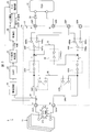
- FIG. 1 is a circuit diagram showing a state (arc presence / absence determination state) when the system is operating normally in the photovoltaic power generation system according to the embodiment of the present invention.
- the solar power generation system 1 includes a plurality of solar cells 11, a relay circuit 12, and a power conditioning system (hereinafter referred to as PCS) 13, as shown in FIG. Furthermore, a current transformer (arc signal detection unit) 21, an amplifier circuit (arc signal detection unit) 22, a filter (arc signal detection unit) 23, an arc presence / absence determination unit 24, an arc identification unit 25, and a control unit 26 are provided.
- the arc presence / absence determination unit 24, the arc identification unit 25, and the control unit 26 are configured by a microcomputer, for example.
- the protection device 5 includes a relay circuit 12, a current transformer 21, an amplifier circuit 22, a filter 23, an arc presence / absence determination unit 24, an arc identification unit 25, and a control unit 26.
- the relay circuit 12 is provided on the relay board 14 and has a plurality of relays (relays).
- the relay board 14 has an input P terminal 31P and an input N terminal 31N along one edge, and an output P terminal 32P, an output N terminal 32N, and a measurement P terminal 33P along the opposite edge. And a measurement N terminal 33N.
- the solar cell 11 is connected to the input P terminal 31P and the input N terminal 31N
- the PCS 13 is connected to the output P terminal 32P and the output N terminal 32N.
- a diode 29 is provided in the forward direction between the output P terminal 32P and the PCS 13.
- the measurement P terminals 33P and 33N are terminals for connecting measurement devices and are not used in the operation of the present embodiment.
- a P-side first relay 41P and a P-side fourth relay 44P are provided in the P-side first conduction path 34P between the input P terminal 31P and the output P terminal 32P from the input P terminal 31P to the output P terminal 32P. It is provided in series. Similarly, an N-side first relay 41N and an N-side fourth relay 44N are provided in series on the N-side first energization path 34N between the input N terminal 31N and the output N terminal 32N.
- the P-side first relay 41P and the P-side fourth relay 44P in the P-side first energization path 34P are connected by a second energizing path 35, and the second energizing path 35 is provided with a second relay 42 that opens and closes the second energizing path 35.
- the third energization path 36 is connected by a P-side third relay 43P and an N-side third relay 43N that open and close the third energization path 36 in series.
- the P-side third relay 43P and the N-side third relay 43N are latch relays.
- the P-side fourth relay 44P has a movable contact 44Pa, a fixed contact 44Pb, and a fixed contact 44Pc.
- the N-side fourth relay 44N has a movable contact 44Na, a fixed contact 44Nb, and a fixed contact 44Nc.
- the movable contact 44Pa is connected to the other terminal of the P-side first relay 41P and one terminal of the second relay 42, the fixed contact 44Pb is connected to the output P terminal 32P, and the fixed contact 44Pc is connected to the measurement P terminal 33P. ing.
- the movable contact 44Na is connected to the other terminal of the N-side first relay 41N and the other terminal of the second relay 42, the fixed contact 44Nb is connected to the output N terminal 32N, and the fixed contact 44Nc is the measurement N terminal 33N. Connected with.
- the current transformer 21 is disposed in the P-side first conduction path 34P and detects an AC signal flowing through the P-side first conduction path 34P.
- the AC signal includes arc noise (arc signal) generated by the arc when the arc is generated in the photovoltaic power generation system 1.
- the current transformer 21 may be disposed in the N-side first conduction path 34N.
- the amplifying circuit 22 amplifies the AC signal detected by the current transformer 21.
- the filter 23 extracts a signal having a predetermined frequency corresponding to arc noise from the AC signal.
- the arc presence / absence determination unit 24 determines whether or not an arc is generated based on the signal output from the filter 23.
- the arc identification unit 25 determines whether the arc is a series arc based on a change in arc noise accompanying the control of the second relay 42 by the control unit 26. Or parallel arc.
- the control unit 26 controls the switching operation of the P-side fourth relay 44P and the N-side fourth relay 44N. Further, according to the determination result (determination result) in the arc presence / absence determination unit 24 and the arc identification result in the arc identification unit 25, the P-side first relay 41P, the N-side first relay 41N, the second relay 42, and The on / off operation of the P-side third relay 43P and the N-side third relay 43N is controlled.
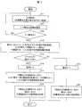
- FIG. 2 is a flowchart showing the operation of the photovoltaic power generation system 1.
- the AC signal when an AC signal flows through the P-side first current path 34P, the AC signal is detected by the current transformer 21 and amplified by the amplifier circuit 22. If the AC signal contains arc noise, the arc noise is extracted by the filter 23 and input to the arc presence / absence determination unit 24 (arc signal detection step). Based on the signal input from the filter 23, the arc presence / absence determination unit 24 monitors the presence / absence of arc generation (arc noise presence / absence) in the photovoltaic power generation system 1 (S12, arc presence / absence determination step).
- FIG. 3 is a circuit diagram showing a state (arc identification state) of the photovoltaic power generation system 1 when the occurrence of an arc is detected.
- the arc identifying unit 25 determines whether or not arc noise has been reduced by turning on the second relay 42 (S15). If the arc noise is reduced as a result of this determination, the arc is identified as a parallel arc (S16, arc identification step). In addition, in order to detect reliably whether it is a parallel arc, you may repeat the process of S14 and S15 several times.
- FIG. 4 is a circuit diagram showing a state of the photovoltaic power generation system 1 when the arc is a parallel arc. As described above, the parallel arc is eliminated by short-circuiting the P terminal and the N terminal of the solar cell 11.
- FIG. 5 is a circuit diagram showing a state after the stop process of the photovoltaic power generation system 1 when a parallel arc occurs.
- the short circuit state between the P terminal and the N terminal of the solar cell 11 is maintained, and the P-side and N-side first conduction paths 34P and 34N between the solar cell 11 and the PCS 13 are opened.
- the P terminal and N terminal of the solar cell 11 remain short-circuited, the state in which the parallel arc is eliminated is maintained.
- the arc identifying unit 25 identifies the arc as a series arc (S19, arc identifying step).
- FIG. 6 is a circuit diagram illustrating a state after the stop process of the photovoltaic power generation system 1 when a series arc is generated.
- the P-side and N-side first current paths 34P and 34N between the solar cell 11 and the PCS 13 are opened. Further, the space between the P terminal and the N terminal of the solar cell 11 is also opened.
- the solar power generation system 1 of the present embodiment is detected by the current transformer 21 in the operation state of the solar power generation system 1 (the state in which the power generated by the solar battery 11 is output).
- the occurrence of an arc is detected based on the AC signal (arc noise)
- the second relay 42 which is a relay for identifying the arc type, is turned on. Judging whether to decrease or not. If the arc noise decreases as a result of this determination, the arc is identified as a parallel arc.
- the arc is identified as a series arc, the P-side and N-side first relays 41P and 41N are turned off, and the P-side and N-side first current paths from the solar cell 11 are turned off. 34P and 34N are shut off.
- the relay circuit 12 from the solar cell 11 to the PCS 13 does not require an element such as a capacitor that easily deteriorates an AC signal (arc noise) or an element that easily breaks down. It is possible to accurately determine the presence / absence of occurrence and whether the arc is a parallel arc or a series arc, and can have high reliability.
- the second relay 42 which is an arc type identifying relay, is turned on, and the P terminal and the N terminal of the solar cell 11 are short-circuited by the second current path 35, In this state, when the arc is identified as a parallel arc, the P-side and N-side third relays 43P and 43N for eliminating the parallel arc are turned on, and the P terminal of the solar cell 11 is connected by the third current path 36. And the N terminal are short-circuited.
- the above-described ON operation of the P-side and N-side third relays 43P and 43N is performed simply after the arc identifying unit 25 identifies that the arc is a parallel arc, or the arc identifying unit 25 parallels the arc. This can be done after it has been identified as an arc and it has been confirmed that the arc signal (parallel arc) has decreased. Thereby, a small and inexpensive thing with a low withstand pressure
- the P-side and N-side third relays 43P and 43N that short-circuit the P terminal and N terminal of the solar cell 11 by the third current path 36 are latch relays, the P-side and N-side third relays 43P and 43N Even when the power source that drives the power failure occurs due to an accident or failure, the short-circuited state between the P terminal and the N terminal of the solar cell 11 can be maintained. Thereby, the reliability about the cancellation
- the third energization path 36 includes the P-side third relay 43P and the N-side third relay 43N, and the P-side first energization path 34P includes the P-side first relay 41P and the P-side fourth relay.
- a relay 44P is provided, and an N-side first relay 41N and an N-side fourth relay 44N are provided in the N-side first energization path 34N. Therefore, the breakdown voltage required for each relay can be lowered.
- the present invention is not limited to this, and the third energization path 36 includes only one relay, and either the P-side first energization path 34P or the N-side first energization path 34N includes a relay.
- the third energization path 36 includes the P-side third relay 43P, and the P-side first energization path 34P includes the P-side first relay 41P and the P-side fourth relay 44P, or the third energization path 36 includes The N-side third relay 43N may be provided, and the N-side first energization path 34N may include the N-side first relay 41N and the N-side fourth relay 44N.
- the above-described configuration for short-circuiting the positive electrode and the negative electrode of the solar cell 11 when the arc is identified as a parallel arc or a series arc and when the parallel arc is eliminated is in principle solar. It can be applied to other than photovoltaic systems. However, the above configuration is actually applicable only to a photovoltaic power generation system for the following two reasons.
- the protection device for a photovoltaic power generation system of the present invention is provided in a first energization path that outputs the power of a solar cell, and opens and closes the first energization path, and the first relay as viewed from the solar cell.
- a second relay that opens and closes the second energization path and is provided in a second energization path that short-circuits the positive and negative outputs of the solar cell at a subsequent stage; and the first relay as viewed from the solar cell.
- a third relay that opens and closes the third conduction path, and an arc signal indicating the occurrence of an arc is provided in the third conduction path that short-circuits the positive and negative outputs of the solar cell.
- An arc presence / absence determining unit for determining An arc identification unit for determining whether an arc is a parallel arc or a series arc based on the arc signal in an arc identification state in which the first and second relays are closed and the third relay is open, and the presence or absence of the arc
- the first to third relays are set to the arc identification state, and when the arc is determined to be a series arc by the arc identification unit, The first relay is in an open state, and when the arc is determined to be a parallel arc by the arc identification unit, a control unit is provided that causes the third relay to be closed from the arc identification state.
- the solar power generation system is in an arc presence / absence determination state in which the first relay is closed and the second and third relays are open in a normal state where no arc is generated. .
- the arc presence / absence determination unit determines whether or not an arc has occurred based on the arc signal detected by the arc signal detection unit. If it is determined by this determination that an arc has occurred, the control unit sets the first to third relays to an arc identification state in which the first and second relays are closed and the third relay is open.
- the arc identification unit determines whether the arc is a series arc or a parallel arc based on the arc signal in the arc identification state. As a result of this determination, if the arc is a series arc, the control unit opens the first relay. Thereby, a series arc can be eliminated.
- the control unit closes the third relay. Thereby, a parallel arc can be eliminated.
- the arc current is determined based on the arc signal. It is possible to accurately determine the presence or absence of occurrence and to identify whether the arc is a parallel arc or a series arc, and can have high reliability.
- the closing operation of the third relay is a state in which the arc signal is reduced, That is, it can be performed in a state where parallel arcs are reduced. Therefore, a small and inexpensive relay with a low required withstand voltage can be used for the third relay.
- the control unit determines that the arc is identified as a parallel arc by the arc identification unit, and the arc signal determination unit determines that the arc signal has decreased.
- the third relay may be closed from the arc identification state.
- the switching of the third relay that closes the third relay from the arc identification state is a state where the arc signal is reduced, that is, a state where the parallel arc is reduced. It is done at.
- the third relay may be a latch relay.
- the switching operation of the third relay to the closed state is performed in a state in which the arc signal is reduced, that is, in a state in which the parallel arc is reduced. Can be used.
- the power source which drives a 3rd relay makes a power failure by an accident, a failure, etc. by making the 3rd relay which makes the positive / negative output of a solar cell a short circuit state into a latch relay, the positive / negative of a solar cell The short circuit state of the output can be maintained. Moreover, since the short circuit of the positive / negative output of a solar cell is performed by the latch relay, the quick switching operation to this state is possible. Thereby, the reliability about the cancellation
- the first to third relays are arranged on the side close to the solar cell, the third relay is provided at the rear stage of the third relay, The second relay may be arranged after the first relay.
- the arrangement state of each relay can be set to the optimum arrangement state. For example, when a parallel arc occurs, the positive and negative outputs of the solar cell can be short-circuited by the third relay regardless of the state of the first relay. Moreover, when a series arc generate
- the solar power generation system protection method of the present invention detects an arc signal indicating the occurrence of an arc from a first current path that outputs the power of the solar cell, and A second energization path that closes the first relay that opens and closes the first energization path and that short-circuits the positive and negative outputs of the solar cell at a position subsequent to the first relay as viewed from the solar cell.
- An arc presence / absence determining step for determining whether or not an arc is generated based on the arc signal in an arc presence / absence determination state, and an arc identification in which the first and second relays are closed and the third relay is open
- An arc identifying step for identifying whether the arc is a parallel arc or a series arc based on the arc signal in a state, and when the arc is determined to be a series arc in the arc identifying step,
- the present invention can be suitably used as a protection device for a power generation system using solar cells.
Landscapes
- Engineering & Computer Science (AREA)
- Power Engineering (AREA)
- Photovoltaic Devices (AREA)
- Testing Of Short-Circuits, Discontinuities, Leakage, Or Incorrect Line Connections (AREA)
- Emergency Protection Circuit Devices (AREA)
Abstract
簡単かつ高信頼性の構成にて直列、並列アークを検知し、解消する。太陽光発電システムの保護装置は、第1リレー(41P,41N)が閉、第2,第3リレー(42,43p,43N)が開でアーク有無を判定し、第1リレー(41P,41N)、第2リレー(42)が閉で並列,直列アークを識別し、直列アーク発生で第1リレー(41P,41N)を開、並列アーク発生で第3リレー(43p,43N)を閉とする。
Description
本発明は、太陽光発電システムにおいて発生した並列アークおよび直列アークからシステムを保護する太陽光発電システムの保護装置および太陽光発電システムの保護方法に関する。
従来、太陽光発電システムは、太陽電池により発電された電力が、昇圧器および直流交流変換器等を含むパワーコンディショナーを介して、電力送電網に供給されるようになっている。このような太陽光発電システムでは、システム内の回路等の故障により回路にアークを生じることがある。アークが発生した場合、アークの発生部分は高温になり、火災等を起こす恐れがある。このため、太陽光発電システムには、アークからシステムを保護する保護装置が備えられている。
上記アークには直列アークと並列アークとがあり、これらアークごとにアークを解消するための対応策が異なる。このため、保護装置は、アークの発生を検知し、かつ発生したアークが直列アークか並列アークかを識別する機能、並びに直列アークおよび並列アークを解消する機能を備えている。このような保護装置については、特許文献1および2に開示された構成が知られている。
特許文献1に記載の構成では、太陽電池(光電発電機)にて発電された電力が、インバータを介して電力送電網(電力グリッド)に供給される。太陽電池からインバータに至るDC電力線には、回路遮断器が設けられ、この回路遮断器と並列にキャパシタが設けられている。また、上記DC電力線において、回路遮断器の後段には電流センサが設けられ、電流センサの後段には、太陽電池の正極と負極とを短絡させる短絡スイッチが設けられている。
特許文献1に記載の構成では、電流センサからの出力信号に基づいてAC信号が検出された場合に、回路遮断器をオフ(遮断状態)にし、キャパシタを介してDC電力線を流れるAC信号が減少すれば、直列アークが発生していると判定する。この場合、直列アークは回路遮断器をオフにしていることにより解消される。
一方、AC信号が減少しなければ、AC信号は妨害源または並列アークによるものと判定する。この場合には、回路遮断器をオン(導通状態)にし、かつ短絡スイッチをオン(導通状態)にする。これにより、AC信号が減少すれば、並列アークが発生していると判定し、AC信号が減少しなければAC信号は妨害源によるものと判定する。並列アークが発生している場合、並列アークは短絡スイッチをオンにすることにより解消される。
また、特許文献2に記載の構成では、特許文献1の場合と同様に、太陽電池(太陽電池発電装置)にて発電された電力が、インバータを介して電力送電網に供給される。太陽電池からインバータに至るDC電力線には、回路遮断器(断路器)およびアークセンサが設けられ、回路遮断器とアークセンサとの間には、太陽電池の正極と負極とを短絡させる短絡スイッチが設けられている。アークセンサは、インバータに付設された電力管理用コントローラ(MPPT)に接続されている。
特許文献2に記載の構成では、MPPTが、アークセンサによる検出信号からアークの有無を判定し、さらに電力管理(MPP)を調整してアークの電力変化を検出し、アークの電力が低下した場合には、電力管理(MPP)の調整方向に基づいて、アークが直列アークか並列アークかを判定するようになっている。また、特許文献1の場合と同様に、アークが直列アークの場合には、回路遮断器をオフにし、アークが並列アークの場合には、短絡スイッチをオンにする。
特許文献1に記載の構成では、上記のように、回路遮断器と並列にキャパシタが設けられ、AC信号が検出された場合において、回路遮断器をオフ(遮断状態)にし、キャパシタを介してDC電力線を流れるAC信号が減少した場合に、直列アークが発生していると判定している。
しかしながら、AC信号は、キャパシタを通過した後に電流センサにより検出されるので、キャパシタを通過する際に劣化し易く、電流センサにより正確に検出し難くなる恐れがある。また、キャパシタは、部品の特性として耐久性に問題があり、高耐圧が要求される電力回路では故障の原因になり易い。このため、キャパシタを使用することは保護装置の信頼性を低下させる恐れがあるという問題点を有している。
また、特許文献2に記載の構成では、上記のように、MPPTが、アークセンサによる検出信号からアークの有無を判別し、電力管理(MPP)を調整してアークの電力変化を検出し、アークにおいて電力が低下した場合に、電力管理(MPP)の調整方向に基づいて、アークが直列アークか並列アークかを識別するようになっている。このため、アークが直列アークか並列アークかを識別するための構成が複雑であるという問題点を有している。
したがって、本発明は、太陽光発電システムでのアークの発生を検知し、発生したアークが直列アークか並列アークかを識別し、それらアークを解消する機能を簡単かつ信頼性の高い構成にて実現することができる太陽光発電システムの保護装置および太陽光発電システムの保護方法の提供を目的としている。
上記の課題を解決するために、本発明の太陽光発電システムの保護装置は、太陽電池の電力を出力する第1通電路に設けられ、前記第1通電路を開閉する第1リレーと、前記太陽電池から見て前記第1リレーの後段の位置にて、前記太陽電池の正負の出力を短絡状態とする第2通電路に設けられ、前記第2通電路を開閉する第2リレーと、前記太陽電池から見て前記第1リレーの前段の位置にて、前記太陽電池の正負の出力を短絡状態とする第3通電路に設けられ、前記第3通電路を開閉する第3リレーと、アークの発生を示すアーク信号を前記第1通電路から検出するアーク信号検出部と、前記第1リレーが閉状態かつ前記第2および前記第3リレーが開状態であるアーク有無判定状態での前記アーク信号に基づいてアークの発生の有無を判定するアーク有無判定部と、前記第1および第2リレーが閉状態かつ前記第3リレーが開状態であるアーク識別状態での前記アーク信号に基づいてアークが並列アークか直列アークかを判定するアーク識別部と、前記アーク有無判定部にてアーク発生と判定された場合に、前記第1から第3リレーを前記アーク識別状態とし、前記アーク識別部にてアークが直列アークと判定された場合に、前記アーク識別状態から前記第1リレーを開状態とし、前記アーク識別部にてアークが並列アークと判定された場合に、前記アーク識別状態から前記第3リレーを閉状態とする制御部とを備えていることを特徴としている。
本発明の構成によれば、太陽光発電システムでのアークの発生を検知し、発生したアークが直列アークか並列アークかを識別し、それらアークを解消する機能を簡単かつ信頼性が高く、さらに小型かつ廉価の構成にて実現することができる。
本発明の実施の形態を図面に基づいて以下に説明する。図1は、本発明の実施の形態の太陽光発電システムにおける、システムが正常に動作している場合の状態(アーク有無判定状態)を示す回路図である。
太陽光発電システム1は、図1に示すように、複数の太陽電池11、リレー回路12、パワーコンディショニングシステム(以下、PCSと称する)13を備えている。さらに、電流トランス(アーク信号検出部)21、増幅回路(アーク信号検出部)22、フィルタ(アーク信号検出部)23、アーク有無判定部24、アーク識別部25および制御部26を備えている。アーク有無判定部24、アーク識別部25および制御部26は例えばマイクロコンピュータによって構成されている。本実施の形態において、保護装置5は、リレー回路12、電流トランス21、増幅回路22、フィルタ23、アーク有無判定部24、アーク識別部25および制御部26により構成されている。
リレー回路12は、リレー基板14に設けられ、複数のリレー(継電器)を有する。リレー基板14は、一方側の端縁部に沿って入力P端子31Pおよび入力N端子31Nを有し、反対側の端縁部に沿って出力P端子32P、出力N端子32N、測定P端子33Pおよび測定N端子33Nを有している。入力P端子31Pおよび入力N端子31Nには太陽電池11が接続され、出力P端子32Pおよび出力N端子32NにはPCS13が接続されている。出力P端子32PとPCS13との間には、順方向にダイオード29が設けられている。測定P端子33P,33Nは、測定機器を接続するための端子であり、本実施の形態の動作においては、使用しない。
入力P端子31Pと出力P端子32Pとの間のP側第1通電路34Pには、入力P端子31Pから出力P端子32Pに向って、P側第1リレー41PおよびP側第4リレー44Pが直列に設けられている。同様に、入力N端子31Nと出力N端子32Nとの間のN側第1通電路34Nには、N側第1リレー41NおよびN側第4リレー44Nが直列に設けられている。
また、P側第1通電路34PにおけるP側第1リレー41PとP側第4リレー44Pとの間、およびN側第1通電路34NにおけるN側第1リレー41NとN側第4リレー44Nとの間は、第2通電路35によって接続され、この第2通電路35には、第2通電路35を開閉する第2リレー42が設けられている。
また、P側第1通電路34Pにおける入力P端子31PとP側第1リレー41Pとの間、およびN側第1通電路34Nにおける入力N端子31NとN側第1リレー41Nとの間は、第3通電路36によって接続され、この第3通電路36には、第3通電路36を開閉するP側第3リレー43PとN側第3リレー43Nとが直列に設けられている。P側第3リレー43PおよびN側第3リレー43Nはラッチリレーである。
P側第4リレー44Pは、可動接点44Pa、固定接点44Pbおよび固定接点44Pcを有する。同様に、N側第4リレー44Nは、可動接点44Na、固定接点44Nbおよび固定接点44Ncを有する。
可動接点44PaはP側第1リレー41Pの他方の端子および第2リレー42の一方の端子と接続され、固定接点44Pbは出力P端子32Pと接続され、固定接点44Pcは測定P端子33Pと接続されている。同様に、可動接点44NaはN側第1リレー41Nの他方の端子および第2リレー42の他方の端子と接続され、固定接点44Nbは出力N端子32Nと接続され、固定接点44Ncは測定N端子33Nと接続されている。
電流トランス21は、P側第1通電路34Pに配置され、P側第1通電路34Pを流れる交流信号を検出する。この交流信号には、太陽光発電システム1においてアークが発生した場合に、アークにより生じたアークノイズ(アーク信号)が含まれる。なお、電流トランス21は、N側第1通電路34Nに配置されていてもよい。
増幅回路22は電流トランス21にて検出された交流信号を増幅する。フィルタ23は、上記交流信号からアークノイズに相当する所定の周波数の信号を取り出す。アーク有無判定部24は、フィルタ23から出力された信号に基づいて、アークが発生しているどうかを判定する。アーク識別部25は、アーク有無判定部24にてアークが発生していると判定された場合に、制御部26による第2リレー42の制御に伴うアークノイズの変化に基づいて、アークが直列アークか並列アークかを識別する。
制御部26は、P側第4リレー44PおよびN側第4リレー44Nの切り替え動作を制御する。また、アーク有無判定部24での判別結果(判定結果)およびアーク識別部25でのアークの識別結果に応じて、P側第1リレー41P、N側第1リレー41N、第2リレー42、並びにP側第3リレー43PおよびN側第3リレー43Nのオンオフ動作を制御する。
上記の構成において、太陽光発電システム1の動作について以下に説明する。図2は、太陽光発電システム1の動作を示すフローチャートである。
図2において、太陽光発電システム1が正常に動作している場合には(S11)、図1に示すように、制御部26の制御により、P側第3リレー43Pはオフ(開状態)となり、P側第1リレー41Pはオン(閉状態)となり、P側第4リレー44Pは可動接点44Paが固定接点44Pbに切り替えられている。同様に、N側第3リレー43Nはオフ(開状態)となり、N側第1リレー41Nはオン(閉状態)となり、N側第4リレー44Nは可動接点44Naが固定接点44Nbに切り替えられている。この状態は、アーク有無判定状態である。この状態では、太陽電池11にて発電された電力は、P側およびN側第1通電路34P,34Nを通じてPCS13に供給される。
上記の状態において、P側第1通電路34Pに交流信号が流れると、その交流信号は電流トランス21にて検出され、増幅回路22にて増幅される。また、上記交流信号にアークノイズが含まれていると、そのアークノイズはフィルタ23にて取り出され、アーク有無判定部24に入力される(アーク信号検出ステップ)。アーク有無判定部24は、フィルタ23から入力される信号に基づいて、太陽光発電システム1におけるアークの発生の有無(アークノイズの有無)を監視している(S12、アーク有無判定ステップ)。
ここで、アーク有無判定部24がアークノイズを検出し、アークの発生と判定すると(S13)、制御部26は、図3に示すように、第2リレー42をオンにする(S14)。これにより、太陽電池11のP端子から、入力P端子31P→P側第3リレー43P→P側第1リレー41P→第2リレー42→N側第1リレー41N→N側第3リレー43N→入力N端子31Nを経て、太陽電池11のN端子に至る短絡回路(電流Iの経路)が形成される。図3は、アークの発生が検出された場合の太陽光発電システム1の状態(アーク識別状態)を示す回路図である。
次に、アーク識別部25は、第2リレー42がオンにされることにより、アークノイズが減少したかどうかを判定する(S15)。この判定の結果、アークノイズが減少していれば、アークは並列アークであると識別する(S16、アーク識別ステップ)。なお、並列アークであるか否かを確実に検出するためS14,S15の処理を複数回繰り返してもよい。
制御部26は、アーク識別部25によりアークが並列アークであると識別されると、図4に示すように、P側第3リレー43PおよびN側第3リレー43Nがオンにする(S17、並列アーク対応ステップ)。これにより、図4に示すように、太陽電池11のP端子から、入力P端子31P→第3通電路36(P側第3リレー43P→N側第3リレー43N)→入力N端子31Nを経て、太陽電池11のN端子に至る短絡回路(電流Iの経路)が形成される。図4は、アークが並列アークである場合の太陽光発電システム1の状態を示す回路図である。上記のように、太陽電池11のP端子とN端子とを短絡させることにより、並列アークは解消される。
その後、制御部26は、図5に示すように、P側第1リレー41PおよびN側第1リレー41N、並びに第2リレー42をオフ(開状態)にさせて、太陽光発電システム1を停止させる(S18)。図5は、並列アークが発生した場合の、太陽光発電システム1の停止処理後の状態を示す回路図である。この場合には、太陽電池11のP端子とN端子との短絡状態が維持され、かつ太陽電池11とPCS13との間のP側およびN側第1通電路34P,34Nが開放される。なお、太陽電池11のP端子とN端子とは短絡させたままであるから、並列アークを解消した状態が維持される。
一方、アーク識別部25は、S15での判定の結果、アークノイズが減少しない場合、あるいは増加する場合には、アークは直列アークであると識別する(S19、アーク識別ステップ)。
制御部26は、アーク識別部25によりアークが直列アークであると識別されると、図6に示すように、図3の状態から、P側第1リレー41PおよびN側第1リレー41Nをオフ(開状態)にするとともに(直列アーク対応ステップ)、第2リレー42をオフ(開状態)にして(S20)、太陽光発電システム1を停止させる。図6は、直列アークが発生した場合の、太陽光発電システム1の停止処理後の状態を示す回路図である。この場合には、太陽電池11とPCS13との間のP側およびN側第1通電路34P,34Nが開放される。また、太陽電池11のP端子とN端子との間も開放される。
以上のように、本実施の形態の太陽光発電システム1は、太陽光発電システム1の動作状態(太陽電池11にて発電された電力を出力している状態)において、電流トランス21により検出された交流信号(アークノイズ)に基づいてアークの発生が検出された場合に、まず、アークを並列アークと仮定して、アーク種類識別用のリレーである第2リレー42をオンにし、アークノイズが減少するかどうかを判定している。また、この判定の結果、アークノイズが減少すればアークを並列アークと識別している。一方、アークノイズが減少しないかあるいは増加すれば、アークを直列アークと識別し、P側およびN側第1リレー41P,41Nをオフにし、太陽電池11からのP側およびN側第1通電路34P,34Nを遮断している。
したがって、アークが直列アークか並列アークかの識別を簡単な構成にて行うことができる。また、太陽電池11からPCS13に至るリレー回路12には、キャパシタ等の、交流信号(アークノイズ)を劣化させやすい素子や故障しやすい素子が不要であるので、上記検出信号に基づいて、アークの発生の有無の判定、およびアークが並列アークであるか直列アークであるかの判定を正確に行うことができ、かつ高い信頼性を備えることができる。
また、アークの種類を識別する場合において、まず、アーク種類識別用のリレーである第2リレー42をオンにして、第2通電路35により太陽電池11のP端子とN端子とを短絡させ、この状態において、アークが並列アークであると識別された場合に、並列アーク解消用のP側およびN側第3リレー43P,43Nをオンにして、第3通電路36により太陽電池11のP端子とN端子とを短絡させている。
この場合、アークが並列アークであれば、第2リレー42をオンにすることにより、アークが減少する。したがって、P側およびN側第3リレー43P,43Nの上記オン動作は、単に、アーク識別部25にてアークが並列アークであると識別された後に、あるいは、アーク識別部25にてアークが並列アークであると識別され、かつアーク信号(並列アーク)が減少したことが確認された後に、行うことができる。これにより、P側およびN側第3リレー43P,43Nには、要求される耐圧が低い小型かつ廉価なものを使用することができる。
また、第3通電路36により太陽電池11のP端子とN端子とを短絡させるP側およびN側第3リレー43P,43Nはラッチリレーであるので、P側およびN側第3リレー43P,43Nを駆動する電源が事故や故障等により停電した場合であっても、太陽電池11のP端子とN端子との短絡状態を維持することができる。これにより、並列アークの解消機能についての信頼性をさらに高めることができる。
なお、太陽光発電システム1では、第3通電路36にP側第3リレー43PおよびN側第3リレー43Nを備え、P側第1通電路34PにP側第1リレー41PおよびP側第4リレー44Pを備え、N側第1通電路34NにN側第1リレー41NおよびN側第4リレー44Nを備えた構成としている。したがって、各リレーに要求される耐圧を低くすることができる。しかしながら、これに限定されることなく、第3通電路36に一つのみのリレーを備え、かつP側第1通電路34PまたはN側第1通電路34Nのいずれか一方のみにリレーを備えた構成としてもよい。すなわち第3通電路36にP側第3リレー43Pを備え、かつP側第1通電路34PにP側第1リレー41PおよびP側第4リレー44Pを備えた構成、または第3通電路36にN側第3リレー43Nを備え、かつN側第1通電路34NにN側第1リレー41NおよびN側第4リレー44Nを備えた構成としてもよい。
なお、太陽光発電システム1において、アークが並列アークか直列アークを識別する際、および並列アークを解消する際に、太陽電池11の正極と負極とを短絡する上記構成は、原理的には太陽光発電システム以外にも適用可能である。しかしながら、上記構成は、下記の2点の理由により、実際には、太陽光発電システムにしか適用できない。
(1)太陽光発電システム以外の一般の電源システムや発電装置において、正極と負極とを短絡すると、数千~数万アンペアといった膨大な突入電流が発生する。このため、並列アークが発生した場合でも正極と負極とを短絡することはない。なお、太陽電池の場合、正極と負極とを短絡した場合の突入電流は、1パネル当たり10アンペア程度である。
(2)太陽光発電以外の電源システムでは、エネルギー遮断のために各種の手法が存在するため、膨大な突入電流が発生する、太陽光発電システム1の上記構成を採用する必要がない。上記の各種の手法としては、例えば電池であれば専用の遮断リレーを設けること、発電機であればクラッチを切断することなどである。一方、太陽光発電システムでは、光が当たると至るところで発電するため、並列アーク遮断の手法が限定される。
〔まとめ〕
本発明の太陽光発電システムの保護装置は、太陽電池の電力を出力する第1通電路に設けられ、前記第1通電路を開閉する第1リレーと、前記太陽電池から見て前記第1リレーの後段の位置にて、前記太陽電池の正負の出力を短絡状態とする第2通電路に設けられ、前記第2通電路を開閉する第2リレーと、前記太陽電池から見て前記第1リレーの前段の位置にて、前記太陽電池の正負の出力を短絡状態とする第3通電路に設けられ、前記第3通電路を開閉する第3リレーと、アークの発生を示すアーク信号を前記第1通電路から検出するアーク信号検出部と、前記第1リレーが閉状態かつ前記第2および前記第3リレーが開状態であるアーク有無判定状態での前記アーク信号に基づいてアークの発生の有無を判定するアーク有無判定部と、前記第1および第2リレーが閉状態かつ前記第3リレーが開状態であるアーク識別状態での前記アーク信号に基づいてアークが並列アークか直列アークかを判定するアーク識別部と、前記アーク有無判定部にてアーク発生と判定された場合に、前記第1から第3リレーを前記アーク識別状態とし、前記アーク識別部にてアークが直列アークと判定された場合に、前記アーク識別状態から前記第1リレーを開状態とし、前記アーク識別部にてアークが並列アークと判定された場合に、前記アーク識別状態から前記第3リレーを閉状態とする制御部とを備えている構成である。
本発明の太陽光発電システムの保護装置は、太陽電池の電力を出力する第1通電路に設けられ、前記第1通電路を開閉する第1リレーと、前記太陽電池から見て前記第1リレーの後段の位置にて、前記太陽電池の正負の出力を短絡状態とする第2通電路に設けられ、前記第2通電路を開閉する第2リレーと、前記太陽電池から見て前記第1リレーの前段の位置にて、前記太陽電池の正負の出力を短絡状態とする第3通電路に設けられ、前記第3通電路を開閉する第3リレーと、アークの発生を示すアーク信号を前記第1通電路から検出するアーク信号検出部と、前記第1リレーが閉状態かつ前記第2および前記第3リレーが開状態であるアーク有無判定状態での前記アーク信号に基づいてアークの発生の有無を判定するアーク有無判定部と、前記第1および第2リレーが閉状態かつ前記第3リレーが開状態であるアーク識別状態での前記アーク信号に基づいてアークが並列アークか直列アークかを判定するアーク識別部と、前記アーク有無判定部にてアーク発生と判定された場合に、前記第1から第3リレーを前記アーク識別状態とし、前記アーク識別部にてアークが直列アークと判定された場合に、前記アーク識別状態から前記第1リレーを開状態とし、前記アーク識別部にてアークが並列アークと判定された場合に、前記アーク識別状態から前記第3リレーを閉状態とする制御部とを備えている構成である。
上記の構成によれば、太陽光発電システムは、アークが発生していない正常な状態において、第1リレーが閉状態かつ第2および第3リレーが開状態であるアーク有無判定状態となっている。このアーク有無判定状態において、アーク有無判定部は、アーク信号検出部により検出されたアーク信号に基づいて、アークの発生の有無を判定する。この判定により、アーク発生と判定されると、制御部は、第1から3リレーを、第1および第2リレーが閉状態かつ第3リレーが開状態であるアーク識別状態とする。
次に、アーク識別部は、アーク識別状態において、アーク信号に基づいてアークが直列アークか並列アークかを判定する。この判定の結果、アークが直列アークであれば、制御部は、第1リレーを開状態とする。これにより、直列アークを解消することができる。
一方、上記の判定の結果、アークが並列アークであれば、第1リレーおよび第2リレーが閉状態とされていることによりアークが減少する。そこで、制御部は、第3リレーを閉状態とする。これにより、並列アークを解消することができる。
したがって、上記の構成によれば、アークが直列アークか並列アークかの判定を簡単な構成にて行うことができる。また、第1通電路および第2通電路には、キャパシタ等の、交流信号であるアーク信号を劣化させやすい素子や故障しやすい素子が設けられていないので、上記アーク信号に基づいて、アークの発生の有無の判定、およびアークが並列アークであるか直列アークであるかの識別を正確に行うことができ、かつ高い信頼性を備えることができる。
また、並列アークが発生した場合に、3リレーを閉状態として第3通電路により太陽電池の正負の出力を短絡状態とする場合において、第3リレーの閉動作は、アーク信号が減少した状態、すなわち並列アークが減少した状態にて行うことができる。したがって、第3リレーには、要求される耐圧が低い小型かつ廉価のものを使用することができる。
上記の太陽光発電システムの保護装置において、前記制御部は、前記アーク識別部にてアークが並列アークと識別され、かつ前記アーク有無判定部にて前記アーク信号が減少したと判定された場合に、前記アーク識別状態から前記第3リレーを閉状態とする構成としてもよい。
上記の構成によれば、アークが並列アークと判定された後、アーク識別状態から第3リレーを閉状態とする第3リレーの切り替えは、アーク信号が減少した状態、すなわち並列アークが減少した状態にて行われる。
これにより、第3リレーに要求される耐圧を確実に低下させることができる。
上記の太陽光発電システムの保護装置において、前記第3リレーはラッチリレーである構成としてもよい。
上記の構成によれば、閉状態への第3リレーの切り替え動作は、アーク信号が減少した状態、すなわち並列アークが減少した状態にて行われるので、第3リレーとして、一般に耐圧が低いラッチリレーを使用することができる。
また、太陽電池の正負の出力を短絡状態とする第3リレーをラッチリレーとすることにより、第3リレーを駆動する電源が事故や故障等により停電した場合であっても、太陽電池の正負の出力の短絡状態を維持することができる。また、太陽電池の正負の出力の短絡をラッチリレーにて行っているので、この状態への迅速な切り替え動作が可能となっている。これにより、並列アークの解消機能についての信頼性をさらに高めることができる。
上記の太陽光発電システムの保護装置において、前記第1から第3リレーは、前記太陽電池に近い側に前記第3リレーが配置され、前記第3リレーの後段に前記第1リレーが設けられ、前記第1リレーの後段に前記第2リレーが配置されている構成としてもよい。
上記の構成によれば、各リレーの配置状態を最適な配置状態とすることができる。例えば、並列アークが発生した場合には、第1リレーの状態に関わらず、第3リレーにより、太陽電池の正負の出力を短絡状態とすることができる。また、直列アークが発生した場合には、太陽電池の電力を出力する第1通電路を確実に遮断状態とすることができる。
本発明の太陽光発電システムの保護方法は、上記の課題を解決するために、アークの発生を示すアーク信号を太陽電池の電力を出力する第1通電路から検出するアーク信号検出ステップと、前記第1通電路を開閉する第1リレーを閉状態とし、かつ前記太陽電池から見て前記第1リレーの後段の位置にて、前記太陽電池の正負の出力を短絡状態とする第2通電路を開閉する第2リレー、および前記太陽電池から見て前記第1リレーの前段の位置にて、前記太陽電池の正負の出力を短絡状態とする第3通電路を開閉する第3リレーを開状態としたアーク有無判定状態にて、前記アーク信号に基づいてアークの発生の有無を判定するアーク有無判定ステップと、前記第1および第2リレーが閉状態かつ前記第3リレーが開状態であるアーク識別状態での前記アーク信号に基づいてアークが並列アークか直列アークかを識別するアーク識別ステップと、前記アーク識別ステップにて、アークが直列アークと判定された場合に、前記アーク識別状態から前記第1リレーを開状態とする直列アーク対応ステップと、前記アーク識別ステップにて、アークが並列アークと判定された場合に、前記アーク識別状態から前記第3リレーを閉状態とする並列アーク対応ステップとを備えている構成である。
上記の構成によれば、上記の太陽光発電システムの保護装置と同様の作用効果を奏する。
本発明は上述した実施形態に限定されるものではなく、請求項に示した範囲で種々の変更が可能であり、実施形態に開示された技術的手段を適宜組み合わせて得られる実施形態についても本発明の技術的範囲に含まれる。
本発明は、太陽電池を使用した発電システムの保護装置として好適に利用することができる。
1 太陽光発電システム
5 保護装置
11 太陽電池
12 リレー回路
13 パワーコンディショニングシステム
14 リレー基板
21 電流トランス(アーク信号検出部)
22 増幅回路(アーク信号検出部)
23 フィルタ(アーク信号検出部)
24 アーク有無判定部
25 アーク識別部
26 制御部
34P P側第1通電路
34N N側第1通電路
35 第2通電路
36 第3通電路
41P P側第1リレー
41N N側第1リレー
42 第2リレー
43P P側第3リレー
43N N側第3リレー
44P P側第4リレー
44N N側第4リレー
5 保護装置
11 太陽電池
12 リレー回路
13 パワーコンディショニングシステム
14 リレー基板
21 電流トランス(アーク信号検出部)
22 増幅回路(アーク信号検出部)
23 フィルタ(アーク信号検出部)
24 アーク有無判定部
25 アーク識別部
26 制御部
34P P側第1通電路
34N N側第1通電路
35 第2通電路
36 第3通電路
41P P側第1リレー
41N N側第1リレー
42 第2リレー
43P P側第3リレー
43N N側第3リレー
44P P側第4リレー
44N N側第4リレー
Claims (5)
- 太陽電池の電力を出力する第1通電路に設けられ、前記第1通電路を開閉する第1リレーと、
前記太陽電池から見て前記第1リレーの後段の位置にて、前記太陽電池の正負の出力を短絡状態とする第2通電路に設けられ、前記第2通電路を開閉する第2リレーと、
前記太陽電池から見て前記第1リレーの前段の位置にて、前記太陽電池の正負の出力を短絡状態とする第3通電路に設けられ、前記第3通電路を開閉する第3リレーと、
アークの発生を示すアーク信号を前記第1通電路から検出するアーク信号検出部と、
前記第1リレーが閉状態かつ前記第2および前記第3リレーが開状態であるアーク有無判定状態での前記アーク信号に基づいてアークの発生の有無を判定するアーク有無判定部と、
前記第1および第2リレーが閉状態かつ前記第3リレーが開状態であるアーク識別状態での前記アーク信号に基づいてアークが並列アークか直列アークかを判定するアーク識別部と、
前記アーク有無判定部にてアーク発生と判定された場合に、前記第1から第3リレーを前記アーク識別状態とし、前記アーク識別部にてアークが直列アークと判定された場合に、前記アーク識別状態から前記第1リレーを開状態とし、前記アーク識別部にてアークが並列アークと判定された場合に、前記アーク識別状態から前記第3リレーを閉状態とする制御部とを備えていることを特徴とする太陽光発電システムの保護装置。 - 前記制御部は、前記アーク識別部にてアークが並列アークと識別され、かつ前記アーク有無判定部にて前記アーク信号が減少したと判定された場合に、前記アーク識別状態から前記第3リレーを閉状態とすることを特徴とする請求項1に記載の太陽光発電システムの保護装置。
- 前記第3リレーはラッチリレーであることを特徴とする請求項1または2に記載の太陽光発電システムの保護装置。
- 前記第1から第3リレーは、前記太陽電池に近い側に前記第3リレーが配置され、前記第3リレーの後段に前記第1リレーが設けられ、前記第1リレーの後段に前記第2リレーが配置されていることを特徴とする請求項1から3のいずれか1項に記載の太陽光発電システムの保護装置。
- アークの発生を示すアーク信号を太陽電池の電力を出力する第1通電路から検出するアーク信号検出ステップと、
前記第1通電路を開閉する第1リレーを閉状態とし、かつ前記太陽電池から見て前記第1リレーの後段の位置にて、前記太陽電池の正負の出力を短絡状態とする第2通電路を開閉する第2リレー、および前記太陽電池から見て前記第1リレーの前段の位置にて、前記太陽電池の正負の出力を短絡状態とする第3通電路を開閉する第3リレーを開状態としたアーク有無判定状態にて、前記アーク信号に基づいてアークの発生の有無を判定するアーク有無判定ステップと、
前記第1および第2リレーが閉状態かつ前記第3リレーが開状態であるアーク識別状態での前記アーク信号に基づいてアークが並列アークか直列アークかを識別するアーク識別ステップと、
前記アーク識別ステップにて、アークが直列アークと判定された場合に、前記アーク識別状態から前記第1リレーを開状態とする直列アーク対応ステップと、
前記アーク識別ステップにて、アークが並列アークと判定された場合に、前記アーク識別状態から前記第3リレーを閉状態とする並列アーク対応ステップとを備えていることを特徴とする太陽光発電システムの保護方法。
Priority Applications (2)
| Application Number | Priority Date | Filing Date | Title |
|---|---|---|---|
| US15/321,749 US9831825B2 (en) | 2014-07-29 | 2015-02-24 | Solar photovoltaic system protecting apparatus and solar photovoltaic system protecting method |
| DE112015003462.5T DE112015003462B4 (de) | 2014-07-29 | 2015-02-24 | Schutzvorrichtung für Photovoltaiksystem und Schutzverfahren für Photovoltaiksystem |
Applications Claiming Priority (2)
| Application Number | Priority Date | Filing Date | Title |
|---|---|---|---|
| JP2014-154199 | 2014-07-29 | ||
| JP2014154199A JP6299507B2 (ja) | 2014-07-29 | 2014-07-29 | 太陽光発電システムの保護装置および太陽光発電システムの保護方法 |
Publications (1)
| Publication Number | Publication Date |
|---|---|
| WO2016017195A1 true WO2016017195A1 (ja) | 2016-02-04 |
Family
ID=55217100
Family Applications (1)
| Application Number | Title | Priority Date | Filing Date |
|---|---|---|---|
| PCT/JP2015/055262 Ceased WO2016017195A1 (ja) | 2014-07-29 | 2015-02-24 | 太陽光発電システムの保護装置および太陽光発電システムの保護方法 |
Country Status (4)
| Country | Link |
|---|---|
| US (1) | US9831825B2 (ja) |
| JP (1) | JP6299507B2 (ja) |
| DE (1) | DE112015003462B4 (ja) |
| WO (1) | WO2016017195A1 (ja) |
Cited By (2)
| Publication number | Priority date | Publication date | Assignee | Title |
|---|---|---|---|---|
| JP6061260B1 (ja) * | 2016-06-15 | 2017-01-18 | 国立研究開発法人産業技術総合研究所 | 太陽光発電システムの感電防止回路 |
| JP2019041515A (ja) * | 2017-08-25 | 2019-03-14 | 国立研究開発法人産業技術総合研究所 | 太陽光発電システムの不具合検知回路 |
Families Citing this family (7)
| Publication number | Priority date | Publication date | Assignee | Title |
|---|---|---|---|---|
| JP6333869B2 (ja) * | 2016-01-25 | 2018-05-30 | ファナック株式会社 | 回路遮断システム |
| DE112017003081T5 (de) * | 2016-06-21 | 2019-03-14 | Mitsubishi Electric Corporation | Schutzvorrichtung für eine elektrische dc-schaltung und lichtbogen-detektionsverfahren |
| US11277000B2 (en) | 2016-06-21 | 2022-03-15 | Mitsubishi Electric Corporation | DC electrical circuit protection apparatus and ARC detection method |
| US11088528B2 (en) * | 2017-02-14 | 2021-08-10 | Panasonic Intellectual Property Management Co., Ltd. | Arc detection circuit, switch system, power conditioner system and arc detection method |
| KR101882466B1 (ko) * | 2017-05-16 | 2018-08-27 | (주)동천기공 | 미세 저항변화에 의한 고장검출과 센서 모니터링을 통한 출력 차단이 가능한 에너지저장시스템 |
| KR102873173B1 (ko) * | 2019-05-02 | 2025-11-20 | 한국전자기술연구원 | 화재 예방을 위한 태양광 접속반의 아크 검출 및 제거를 위한 장치 및 이를 위한 방법 |
| US11923670B2 (en) * | 2020-03-11 | 2024-03-05 | Panasonic Intellectual Property Management Co., Ltd. | ARC detection device, solar inverter, indoor wiring system, circuit breaker, solar panel, solar panel attachment module, and junction box |
Citations (3)
| Publication number | Priority date | Publication date | Assignee | Title |
|---|---|---|---|---|
| JP2008166277A (ja) * | 2006-12-28 | 2008-07-17 | General Electric Co <Ge> | 直列アーク事故電流遮断器及び方法 |
| JP2013542699A (ja) * | 2010-08-31 | 2013-11-21 | エレンベルガー ウント ペンスゲン ゲゼルシャフト ミット ベシュレンクテル ハフツング | アークタイプを識別後に太陽光発電システムを安全に遮断するための方法および装置 |
| JP2014509396A (ja) * | 2011-02-28 | 2014-04-17 | エスエムエー ソーラー テクノロジー アーゲー | 電力回路におけるアーク故障を検出するための方法およびシステム |
Family Cites Families (15)
| Publication number | Priority date | Publication date | Assignee | Title |
|---|---|---|---|---|
| EP2118980B1 (en) * | 2007-03-06 | 2019-09-11 | Xantrex Technology, Inc. | Bipolar dc to ac power converter with dc ground fault interrupt |
| EP2048679B1 (de) * | 2007-10-12 | 2010-04-07 | SMA Solar Technology AG | Lasttrenner-Anordnung |
| DE202009004198U1 (de) * | 2009-03-25 | 2010-08-12 | Ellenberger & Poensgen Gmbh | Trennschalter zur galvanischen Gleichstromunterbrechung |
| US20140009163A1 (en) * | 2011-04-08 | 2014-01-09 | Atreus Enterprises Limited | Apparatus for testing an arc fault detector |
| US20120319489A1 (en) * | 2011-06-15 | 2012-12-20 | Mccaslin Shawn R | Power Shuffling Solar String Equalization System |
| US8619396B2 (en) * | 2011-06-24 | 2013-12-31 | Renewable Power Conversion, Inc. | Renewable one-time load break contactor |
| DE102012109012B4 (de) * | 2011-10-07 | 2016-09-15 | Sma Solar Technology Ag | Schaltungsanordnung für ein Solarkraftwerk mit einer Gleichspannungsquelle für eine Offsetspannung |
| DE102011116135A1 (de) * | 2011-10-15 | 2013-04-18 | Kostal Industrie Elektrik Gmbh | Photovoltaikanlage |
| DE102011056577C5 (de) * | 2011-12-19 | 2015-02-19 | Sma Solar Technology Ag | Schaltungsanordnung zur Unterdrückung eines bei einem Schaltvorgang auftretenden Lichtbogens |
| US8922958B2 (en) * | 2012-06-12 | 2014-12-30 | General Electric Company | Method and systems for discharging energy from an electrical fault |
| US8958182B2 (en) * | 2012-08-27 | 2015-02-17 | Eaton Corporation | Method and apparatus for enhancing arc fault signal for detection in photovoltaic system |
| US20140063662A1 (en) * | 2012-08-27 | 2014-03-06 | Eco Power Design LLC | Solar panel, power inverter, theft and arc protection system and methods of protection |
| US20140091808A1 (en) * | 2012-09-28 | 2014-04-03 | Arc Suppression Technologies | Contact separation detector and methods therefor |
| US9413155B2 (en) * | 2013-02-19 | 2016-08-09 | Kenneth Gerald Blemel | System to protect from unsafe conditions in an electrical power system |
| US20150103454A1 (en) * | 2013-10-14 | 2015-04-16 | Solarbos, Inc. | System for Combining Direct Current Power from Multiple Inputs |
-
2014
- 2014-07-29 JP JP2014154199A patent/JP6299507B2/ja active Active
-
2015
- 2015-02-24 DE DE112015003462.5T patent/DE112015003462B4/de not_active Expired - Fee Related
- 2015-02-24 US US15/321,749 patent/US9831825B2/en not_active Expired - Fee Related
- 2015-02-24 WO PCT/JP2015/055262 patent/WO2016017195A1/ja not_active Ceased
Patent Citations (3)
| Publication number | Priority date | Publication date | Assignee | Title |
|---|---|---|---|---|
| JP2008166277A (ja) * | 2006-12-28 | 2008-07-17 | General Electric Co <Ge> | 直列アーク事故電流遮断器及び方法 |
| JP2013542699A (ja) * | 2010-08-31 | 2013-11-21 | エレンベルガー ウント ペンスゲン ゲゼルシャフト ミット ベシュレンクテル ハフツング | アークタイプを識別後に太陽光発電システムを安全に遮断するための方法および装置 |
| JP2014509396A (ja) * | 2011-02-28 | 2014-04-17 | エスエムエー ソーラー テクノロジー アーゲー | 電力回路におけるアーク故障を検出するための方法およびシステム |
Cited By (2)
| Publication number | Priority date | Publication date | Assignee | Title |
|---|---|---|---|---|
| JP6061260B1 (ja) * | 2016-06-15 | 2017-01-18 | 国立研究開発法人産業技術総合研究所 | 太陽光発電システムの感電防止回路 |
| JP2019041515A (ja) * | 2017-08-25 | 2019-03-14 | 国立研究開発法人産業技術総合研究所 | 太陽光発電システムの不具合検知回路 |
Also Published As
| Publication number | Publication date |
|---|---|
| US20170141722A1 (en) | 2017-05-18 |
| DE112015003462T5 (de) | 2017-04-20 |
| US9831825B2 (en) | 2017-11-28 |
| JP2016032369A (ja) | 2016-03-07 |
| JP6299507B2 (ja) | 2018-03-28 |
| DE112015003462B4 (de) | 2020-11-12 |
Similar Documents
| Publication | Publication Date | Title |
|---|---|---|
| JP6299507B2 (ja) | 太陽光発電システムの保護装置および太陽光発電システムの保護方法 | |
| JP6132919B2 (ja) | 直流発電システムおよび直流発電システムの保護方法 | |
| CN104898008B (zh) | 电气设备中的串联电弧的探测 | |
| US9070797B2 (en) | Photovoltaic installation | |
| JP5778787B2 (ja) | 電力回路におけるアーク故障を検出するための方法およびシステム | |
| US12095256B2 (en) | Fault isolation apparatus, direct current boost apparatus, and inverter apparatus | |
| JP6246062B2 (ja) | 直流発電システムおよび直流発電システムの保護方法 | |
| US20140191589A1 (en) | Safety device for a photovoltaic system | |
| JP5888972B2 (ja) | 太陽光発電システム | |
| CN104919671B (zh) | 用于保护一个光伏发电机的多个串免于反向电流的方法和装置 | |
| WO2012026447A1 (ja) | 太陽光発電用集電箱 | |
| JP6405807B2 (ja) | 太陽光発電システムの検査装置および太陽光発電システムの検査方法 | |
| EP2608341A1 (en) | Grounding device | |
| JPWO2020174657A1 (ja) | 太陽光発電システム | |
| JP2018028498A (ja) | アーク故障検出システム | |
| CN115663769B (zh) | 光伏发电系统直流并联电弧保护及定位系统和方法 | |
| JP2015002606A (ja) | Dcアーク検知装置 | |
| JP2016157364A (ja) | 電力制御装置及びその制御方法 | |
| CN118432014A (zh) | 功率变换装置及其短路保护方法、光伏发电系统 | |
| JP6671769B2 (ja) | 太陽光発電システム | |
| JP7145011B2 (ja) | パワーコンディショナ | |
| KR20150081943A (ko) | 누전차단기 | |
| JP2014007909A (ja) | 電力変換装置 | |
| KR101616797B1 (ko) | 누전차단기 | |
| EP4645620A1 (en) | Power supply system |
Legal Events
| Date | Code | Title | Description |
|---|---|---|---|
| 121 | Ep: the epo has been informed by wipo that ep was designated in this application |
Ref document number: 15827599 Country of ref document: EP Kind code of ref document: A1 |
|
| WWE | Wipo information: entry into national phase |
Ref document number: 15321749 Country of ref document: US |
|
| WWE | Wipo information: entry into national phase |
Ref document number: 112015003462 Country of ref document: DE |
|
| 122 | Ep: pct application non-entry in european phase |
Ref document number: 15827599 Country of ref document: EP Kind code of ref document: A1 |