EP2118980B1 - Bipolar dc to ac power converter with dc ground fault interrupt - Google Patents
Bipolar dc to ac power converter with dc ground fault interrupt Download PDFInfo
- Publication number
- EP2118980B1 EP2118980B1 EP07752585.5A EP07752585A EP2118980B1 EP 2118980 B1 EP2118980 B1 EP 2118980B1 EP 07752585 A EP07752585 A EP 07752585A EP 2118980 B1 EP2118980 B1 EP 2118980B1
- Authority
- EP
- European Patent Office
- Prior art keywords
- monopole
- bipolar
- contactor
- fuse
- ground
- Prior art date
- Legal status (The legal status is an assumption and is not a legal conclusion. Google has not performed a legal analysis and makes no representation as to the accuracy of the status listed.)
- Active
Links
Images


Classifications
-
- H—ELECTRICITY
- H02—GENERATION; CONVERSION OR DISTRIBUTION OF ELECTRIC POWER
- H02H—EMERGENCY PROTECTIVE CIRCUIT ARRANGEMENTS
- H02H3/00—Emergency protective circuit arrangements for automatic disconnection directly responsive to an undesired change from normal electric working condition with or without subsequent reconnection ; integrated protection
- H02H3/16—Emergency protective circuit arrangements for automatic disconnection directly responsive to an undesired change from normal electric working condition with or without subsequent reconnection ; integrated protection responsive to fault current to earth, frame or mass
-
- H—ELECTRICITY
- H02—GENERATION; CONVERSION OR DISTRIBUTION OF ELECTRIC POWER
- H02H—EMERGENCY PROTECTIVE CIRCUIT ARRANGEMENTS
- H02H7/00—Emergency protective circuit arrangements specially adapted for specific types of electric machines or apparatus or for sectionalised protection of cable or line systems, and effecting automatic switching in the event of an undesired change from normal working conditions
- H02H7/10—Emergency protective circuit arrangements specially adapted for specific types of electric machines or apparatus or for sectionalised protection of cable or line systems, and effecting automatic switching in the event of an undesired change from normal working conditions for converters; for rectifiers
- H02H7/12—Emergency protective circuit arrangements specially adapted for specific types of electric machines or apparatus or for sectionalised protection of cable or line systems, and effecting automatic switching in the event of an undesired change from normal working conditions for converters; for rectifiers for static converters or rectifiers
- H02H7/122—Emergency protective circuit arrangements specially adapted for specific types of electric machines or apparatus or for sectionalised protection of cable or line systems, and effecting automatic switching in the event of an undesired change from normal working conditions for converters; for rectifiers for static converters or rectifiers for inverters, i.e. DC/AC converters
- H02H7/1222—Emergency protective circuit arrangements specially adapted for specific types of electric machines or apparatus or for sectionalised protection of cable or line systems, and effecting automatic switching in the event of an undesired change from normal working conditions for converters; for rectifiers for static converters or rectifiers for inverters, i.e. DC/AC converters responsive to abnormalities in the input circuit, e.g. transients in the DC input
-
- H—ELECTRICITY
- H02—GENERATION; CONVERSION OR DISTRIBUTION OF ELECTRIC POWER
- H02H—EMERGENCY PROTECTIVE CIRCUIT ARRANGEMENTS
- H02H7/00—Emergency protective circuit arrangements specially adapted for specific types of electric machines or apparatus or for sectionalised protection of cable or line systems, and effecting automatic switching in the event of an undesired change from normal working conditions
- H02H7/20—Emergency protective circuit arrangements specially adapted for specific types of electric machines or apparatus or for sectionalised protection of cable or line systems, and effecting automatic switching in the event of an undesired change from normal working conditions for electronic equipment
-
- H—ELECTRICITY
- H02—GENERATION; CONVERSION OR DISTRIBUTION OF ELECTRIC POWER
- H02J—CIRCUIT ARRANGEMENTS OR SYSTEMS FOR SUPPLYING OR DISTRIBUTING ELECTRIC POWER; SYSTEMS FOR STORING ELECTRIC ENERGY
- H02J3/00—Circuit arrangements for AC mains or AC distribution networks
- H02J3/38—Arrangements for parallely feeding a single network by two or more generators, converters or transformers
- H02J3/381—Dispersed generators
-
- H—ELECTRICITY
- H02—GENERATION; CONVERSION OR DISTRIBUTION OF ELECTRIC POWER
- H02M—APPARATUS FOR CONVERSION BETWEEN AC AND AC, BETWEEN AC AND DC, OR BETWEEN DC AND DC, AND FOR USE WITH MAINS OR SIMILAR POWER SUPPLY SYSTEMS; CONVERSION OF DC OR AC INPUT POWER INTO SURGE OUTPUT POWER; CONTROL OR REGULATION THEREOF
- H02M7/00—Conversion of AC power input into DC power output; Conversion of DC power input into AC power output
- H02M7/42—Conversion of DC power input into AC power output without possibility of reversal
- H02M7/44—Conversion of DC power input into AC power output without possibility of reversal by static converters
-
- H02J2101/24—
-
- Y—GENERAL TAGGING OF NEW TECHNOLOGICAL DEVELOPMENTS; GENERAL TAGGING OF CROSS-SECTIONAL TECHNOLOGIES SPANNING OVER SEVERAL SECTIONS OF THE IPC; TECHNICAL SUBJECTS COVERED BY FORMER USPC CROSS-REFERENCE ART COLLECTIONS [XRACs] AND DIGESTS
- Y02—TECHNOLOGIES OR APPLICATIONS FOR MITIGATION OR ADAPTATION AGAINST CLIMATE CHANGE
- Y02E—REDUCTION OF GREENHOUSE GAS [GHG] EMISSIONS, RELATED TO ENERGY GENERATION, TRANSMISSION OR DISTRIBUTION
- Y02E10/00—Energy generation through renewable energy sources
- Y02E10/50—Photovoltaic [PV] energy
- Y02E10/56—Power conversion systems, e.g. maximum power point trackers
Definitions
- Embodiments of the invention relates to electrical power converters and more specifically, converting power from a bipolar DC source to supply an AC load.
- PV arrays In the United States, two solar photovoltaic (PV) array configurations are permitted by the National Electric Code (NEC), Section 690, grounded and ungrounded.
- NEC National Electric Code
- the maximum voltage of a PV array is limited to 600Vdc with respect to earth in ground systems and 600Vdc in ungrounded systems.
- the NEC also requires that PV systems installed on dwell ings have a means of detecting and interrupting fault currents from the PV array to earth ground. These faults are commonly caused by water intrusion into wiring junction boxes, degradation of the array wiring insulation, or a failure in the solar module insulating materials. These faults can cause a low energy leakage path or a destructive direct current arc.
- the intent of the code, with respect to ground faults, is fire protection, not personnel protection.
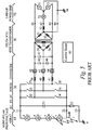
- FIG. 5 shows a circuit topology for a utility grid interactive, PV power converter in accordance with the prior art.
- a typical (PV) power plant a number of solar panels are connected in series. This is represented by solar generators 2 through 5.
- conventional power converters operate from grounded monopolar PV arrays, i.e. arrays with one polarity with respect to ground.
- Fault 1 illustrates a fault scenario where an unwanted current path has developed between solar generators 4 and 5 and earth ground.
- PV array 10 connects to power converter 30 at terminals 21 and 22.
- the earth ground connection for PV array 10 is made through fuse 32 and terminal 23 to ground rod 6. If the current from fault 1 is great enough, fuse 32 will clear, the fault current path will be broken, PV array 10 will become ungrounded and operation of power converter 30 will be locked out by control board 80 until the ground fault is cleared and a manual reset is initiated on control board 80.
- DC to AC converter 30 is a typical 3-phase bridge configuration and operates as a utility grid interactive inverter by regulating sinusoidal 3-phase currents in phase with the voltages across transformer windings 54, 55 and 56.
- Semiconductor switches 33 through 38 are gated on and off at high frequencies by control board 80 to regulate currents through filter inductors 39 through 41.
- Filter inductors 39-41 and filter capacitors 45-47 integrate the high frequency, pulse width modulated output from switches 33-38.
- Reference current waveforms are compared to the actual current measured by sensors 39, 40 and 41.
- Three servo loops on control board 80 regulate undistorted sinusoidal currents into transformer 50. Windings 51, 52 and 53 of transformer 50 are connected to 3-phase power grid 70 at power converter 30 output terminals 61-64.
- isolation transformer 50 is required for level translation. Transformer 50 is also required to boost the voltage of the power converter output to allow the power converter tie into power grid 70 at 120/208Vac or higher.
- JP 01 163 809 , US 2006/0227472 and US 2001/0023703 disclose power converters from photovoltaic source to AC load with DC ground-fault interrupt.
- the invention is an improvement over the prior art because the weight, size, cost and conversion losses of the isolation transformer can be eliminated.
- the maximum DC working voltage of the DC to AC converter can be effectively doubled thereby reducing the current by half for a given power level for an additional cost reductions and performance enhancements.
- Embodiments of the invention provide an apparatus for converting power from a bipolar DC source to supply an AC load.
- the bipolar DC source has a positive and negative monopole, and corresponding voltage potentials, with respect to a common earth ground or with respect to a neutral point of an AC load.
- the apparatus also includes a DC ground fault interrupt circuit having a means for detecting a fault current in either monopole of the bipolar DC source to earth ground or to a neutral point of the AC load and a means of automatically interrupting the flow of said fault current
- Embodiments of the invention provide apparatuses for converting power from a bipolar DC source to supply an AC load.
- the bipolar DC source is a PV array and the AC power is sourced into an electric power grid.
- the bipolar PV array has positive and negative voltage potentials with respect to earth ground.
- the converter is a utility interactive inverter which does not require an isolation transformer at the electric power grid interface.
- Embodiments of the invention include methods of detecting and interrupting DC ground faults in the PV array.
- FIG. 1 illustrates a DC-to-AC power converter in accordance with one embodiment of the invention.
- PV array 1 is connected across input terminals 3 and 4 of the inverter.
- PV array 2 is connected across input terminals 5 and 6.
- Terminals 4 and 5 are connected to earth ground 9 through fuses 7 and 8 respectively.
- Contactor 10 connects terminal 3 to +DC BUS 64 and contactor 12 connects terminal 6 to -DC BUS 65.
- Contactor 11 connects terminals 4 and 5.
- Contactors 10, 11 and 12 are normally open and are closed by commands from control board 90.
- Capacitors 62 and 63 are energy storage elements connected in series across the plus and minus DC buses, 64 and 65. The common connection point of capacitors 62 and 63 is connected to AC neutral at terminal 84.
- Switches 66-71 are typically IGBT (Insulated Gate Bipolar Transistor) devices commanded on and off by control board 90.
- Switches 66-71 and filter inductors 72-74 are arranged in a typical, known, three-phase bridge configuration.
- Capacitors 78-80 provide a second filter pole for each of the three phases and a high frequency return path to DC bus capacitors 62 and 63.
- the inverter is connected to power grid 88 at terminals 81-84.
- Neutral connection 84 is connected to a ground rod to make earth connection 89 as required by the National Electric Code.
- AC power grid 88 could be a typical 120/208Vac commercial service.
- Control board 90 alternately commands switches 66 and 67 into conduction at different on/off ratios.
- a net current is produced, filtered by inductor 72 and capacitor 78, which flows into utility grid phase 85 at terminal 81.
- Control board 90 commands switches 66 and 67 in such a way as to produce a sinusoidal current into AC power grid 88 that is in phase with the voltage at terminal 81 with respect to neutral terminal 84 to achieve unity-power-factor power transfer into utility grid 88.
- the actual current through inductor 72 is measured by current sensor 75 and compared to a desired, sinusoidal reference value to regulate the current through inductor 72 in a classic servo loop.
- Currents into terminals 82 and 83 are produced in the same manner.
- connection at utility grid 88 is a 4-wire, grounded Wye configuration and the DC source is ground referenced as well, each of the three phases operate independently.
- Control and regulation methodologies for utility grid interactive inverters are known and are not part of this invention.
- the invention is power converter topology with a unique arrangement of power components.
- contactors 10, 11 and 12 will be closed and fuses 7 and 8 will be in parallel. The currents through fuses 7 and 8 will effectively be zero. If a fault to ground in either PV array 1 or 2 produces a fault current large enough to clear either fuse 7 or 8 or both, a blown fuse indicator signal is sent to control board 90. In response, control board 90 releases (opens) contactors 10-12. The ground fault current is interrupted when a fuse is or fuses are cleared.
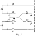
- FIG. 2 illustrates an alternative example where four normally open contactors 24-27 are used.
- fault current to ground, in either PV array 1 or 2 is either sensed by current sensor 28A and compared to a preset trip level on control board 90 or indicating fuse 28B sends a signal to control board 90 when fuse 28B is cleared by ground fault current.
- contactors 24-27 are opened thus interrupting the flow of fault current.
- Resistors 21 and 22 are used to discharge static charge on PV arrays 1 and 2 respectively and to provide a soft voltage reference for said arrays when contactors 24-27 are open.
- FIG. 3 illustrates an alternative example where DC current sensors 37 and 38 measure the differential current in PV arrays 1 and 2 respectively. Any current flowing into terminal 3 must return out of terminal 4. If not, there is a fault to ground equal in magnitude to the difference of these two currents. An analogous method is used for sensing ground fault currents in PV array 2.
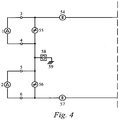
- Figure 4 illustrates an alternative example where two normally open contactors 54 and 57 are used in conjunction with two normally closed contactors 55 and 56.
- contactors 54 and 57 are closed and contactors 55 and 56 are open.
- current sensor 58 detects a ground fault current exceeding a preset trip level
- contactors 54 and 57 are opened and contactors 55 and 56 are closed.
- ground fault current was interrupted by opening the intended earth connection and floating the PV array.
- the voltage potentials across arrays 1 and 2 are short circuited by contactors 55 and 56 respectively, thereby removing any voltage potential to ground and therefore any current to ground.
- PV arrays 1 and 2 remain hard grounded under all conditions.
Landscapes
- Engineering & Computer Science (AREA)
- Power Engineering (AREA)
- Inverter Devices (AREA)
- Emergency Protection Circuit Devices (AREA)
Description
- Embodiments of the invention relates to electrical power converters and more specifically, converting power from a bipolar DC source to supply an AC load.
- In the United States, two solar photovoltaic (PV) array configurations are permitted by the National Electric Code (NEC), Section 690, grounded and ungrounded. The maximum voltage of a PV array is limited to 600Vdc with respect to earth in ground systems and 600Vdc in ungrounded systems. The NEC also requires that PV systems installed on dwell ings have a means of detecting and interrupting fault currents from the PV array to earth ground. These faults are commonly caused by water intrusion into wiring junction boxes, degradation of the array wiring insulation, or a failure in the solar module insulating materials. These faults can cause a low energy leakage path or a destructive direct current arc. The intent of the code, with respect to ground faults, is fire protection, not personnel protection.
-
Figure 5 shows a circuit topology for a utility grid interactive, PV power converter in accordance with the prior art. In a typical (PV) power plant, a number of solar panels are connected in series. This is represented bysolar generators 2 through 5. Typically, conventional power converters operate from grounded monopolar PV arrays, i.e. arrays with one polarity with respect to ground.Fault 1 illustrates a fault scenario where an unwanted current path has developed betweensolar generators PV array 10 connects topower converter 30 atterminals PV array 10 is made throughfuse 32 andterminal 23 toground rod 6. If the current fromfault 1 is great enough,fuse 32 will clear, the fault current path will be broken,PV array 10 will become ungrounded and operation ofpower converter 30 will be locked out bycontrol board 80 until the ground fault is cleared and a manual reset is initiated oncontrol board 80. - DC to
AC converter 30 is a typical 3-phase bridge configuration and operates as a utility grid interactive inverter by regulating sinusoidal 3-phase currents in phase with the voltages acrosstransformer windings Semiconductor switches 33 through 38 are gated on and off at high frequencies bycontrol board 80 to regulate currents throughfilter inductors 39 through 41. Filter inductors 39-41 and filter capacitors 45-47 integrate the high frequency, pulse width modulated output from switches 33-38. Reference current waveforms are compared to the actual current measured bysensors control board 80 regulate undistorted sinusoidal currents intotransformer 50.Windings transformer 50 are connected to 3-phase power grid 70 atpower converter 30 output terminals 61-64. BecausePV array 10 is monopolar and ground referenced and 3-phase power grid 70 is bipolar and ground referenced,isolation transformer 50 is required for level translation. Transformer 50 is also required to boost the voltage of the power converter output to allow the power converter tie intopower grid 70 at 120/208Vac or higher. -
JP 01 163 809 US 2006/0227472 andUS 2001/0023703 disclose power converters from photovoltaic source to AC load with DC ground-fault interrupt. - The invention is an improvement over the prior art because the weight, size, cost and conversion losses of the isolation transformer can be eliminated. In addition the maximum DC working voltage of the DC to AC converter can be effectively doubled thereby reducing the current by half for a given power level for an additional cost reductions and performance enhancements.
- Embodiments of the invention provide an apparatus for converting power from a bipolar DC source to supply an AC load. The bipolar DC source has a positive and negative monopole, and corresponding voltage potentials, with respect to a common earth ground or with respect to a neutral point of an AC load. The apparatus also includes a DC ground fault interrupt circuit having a means for detecting a fault current in either monopole of the bipolar DC source to earth ground or to a neutral point of the AC load and a means of automatically interrupting the flow of said fault current
- Other features and advantages of embodiments of the present invention will be apparent from the accompanying drawings, and from the detailed description, that follows below.
- The invention may be best understood by referring to the following description and accompanying drawings that are used to illustrate embodiments of the invention. In the drawings:
-
Figure 1 illustrates a DC-to-AC power converter in accordance with one embodiment of the invention; -
Figure 2 illustrates an alternative example where four normally open contactors are used; -
Figure 3 illustrates an alternative example where DC current sensors measure the differential current in the PV arrays; -
Figure 4 illustrates an alternative example where two normally open contactors are used in conjunction with two normally closed contactors; and -
Figure 5 shows a circuit topology for a utility grid interactive, PV power converter in accordance with the prior art. - Embodiments of the invention provide apparatuses for converting power from a bipolar DC source to supply an AC load is disclosed. For one such embodiment the bipolar DC source is a PV array and the AC power is sourced into an electric power grid. The bipolar PV array has positive and negative voltage potentials with respect to earth ground. The converter is a utility interactive inverter which does not require an isolation transformer at the electric power grid interface. Embodiments of the invention include methods of detecting and interrupting DC ground faults in the PV array.
- Those of ordinary skill in the art will realize that the following detailed description of various embodiments of the invention is illustrative only and is not intended to be in any way limiting. Other embodiments of the invention will readily suggest themselves to such skilled persons having the benefit of this disclosure. It will be apparent to one skilled in the art that these specific details may not be required to practice embodiments of the invention. In other instances, well-known circuits and devices are shown in block diagram form to avoid obscuring the invention. In the following description of the embodiments, substantially the same parts are denoted by the same reference numerals.
- In the interest of clarity, not all of the features of the implementations described herein are shown and described. It will, of course, be appreciated that in the development of any such actual implementation, numerous implementation-specific devices must be made in order to achieve the developer's specific goals, wherein these specific goals will vary from one implementation to another and from one developer to another. Moreover, it will be appreciated that such a development effort might be complex and time-consuming, but would nevertheless be a routine undertaking of engineering for those of ordinary skill in the art having the benefit of this disclosure.
- While particular embodiments of the invention have been shown and described, it will now be apparent to those skilled in the art having the benefit of this disclosure that many more modifications than mentioned above are possible without departing from the inventive concepts disclosed herein. Moreover, inventive aspects lie in less than all features of a single disclosed embodiment. Thus, the claims following the Detailed Description are hereby expressly incorporated into this Detailed Description, with each claim standing on its own as a separate embodiment of this invention.
-
Figure 1 illustrates a DC-to-AC power converter in accordance with one embodiment of the invention.PV array 1 is connected acrossinput terminals PV array 2 is connected acrossinput terminals Terminals earth ground 9 throughfuses Contactor 10 connects terminal 3 to +DC BUS 64 andcontactor 12 connects terminal 6 to -DC BUS 65.Contactor 11 connectsterminals Contactors control board 90.Capacitors capacitors terminal 84. Semiconductor switches 66-71 are typically IGBT (Insulated Gate Bipolar Transistor) devices commanded on and off bycontrol board 90. Switches 66-71 and filter inductors 72-74 are arranged in a typical, known, three-phase bridge configuration. Capacitors 78-80 provide a second filter pole for each of the three phases and a high frequency return path toDC bus capacitors Neutral connection 84 is connected to a ground rod to makeearth connection 89 as required by the National Electric Code. AC power grid 88 could be a typical 120/208Vac commercial service. -
Control board 90 alternately commandsswitches inductor 72 andcapacitor 78, which flows intoutility grid phase 85 atterminal 81.Control board 90 commands switches 66 and 67 in such a way as to produce a sinusoidal current into AC power grid 88 that is in phase with the voltage at terminal 81 with respect toneutral terminal 84 to achieve unity-power-factor power transfer into utility grid 88. The actual current throughinductor 72 is measured bycurrent sensor 75 and compared to a desired, sinusoidal reference value to regulate the current throughinductor 72 in a classic servo loop. Currents intoterminals - Under normal operating conditions, contactors 10, 11 and 12 will be closed and fuses 7 and 8 will be in parallel. The currents through
fuses PV array fuse board 90. In response,control board 90 releases (opens) contactors 10-12. The ground fault current is interrupted when a fuse is or fuses are cleared. -
Figure 2 illustrates an alternative example where four normally open contactors 24-27 are used. With this topology, fault current, to ground, in eitherPV array current sensor 28A and compared to a preset trip level oncontrol board 90 or indicatingfuse 28B sends a signal to controlboard 90 whenfuse 28B is cleared by ground fault current. In response, contactors 24-27 are opened thus interrupting the flow of fault current.Resistors PV arrays -
Figure 3 illustrates an alternative example where DCcurrent sensors PV arrays terminal 3 must return out ofterminal 4. If not, there is a fault to ground equal in magnitude to the difference of these two currents. An analogous method is used for sensing ground fault currents inPV array 2. -
Figure 4 illustrates an alternative example where two normallyopen contactors contactors normal operation contactors contactors current sensor 58 detects a ground fault current exceeding a preset trip level,contactors contactors Figures 1 through 3 , ground fault current was interrupted by opening the intended earth connection and floating the PV array. In the topology shown inFigure 4 , the voltage potentials acrossarrays contactors Figures 1 through 3 ,PV arrays
Claims (5)
- An apparatus for converting power from a bipolar DC source (1, 2) to supply an AC load (88), the apparatus having plus and minus terminals (64, 65), said apparatus comprising:a bipolar DC source (1, 2) having positive and negative monopoles (3, 4, 5, 6), and corresponding voltage potentials, with respect to a common earth ground (9) or with respect to a neutral point (84) of the AC load;a DC ground fault interrupt circuit including a means for detecting a fault current in either monopole of the bipolar DC source to the common earth ground or to neutral point of the AC load and a means of automatically interrupting the flow of said fault current, the DC ground fault interrupt circuit comprising a first fuse (7), a second fuse (8), a first contactor (10), a second contactor (12) and a third contactor (11), wherein said bipolar DC source having a plus and minus terminal for each monopole, and where the minus terminal (4) of the positive monopole (1) is connected to earth ground through the first fuse (7) and where the plus terminal (5) of the negative monopole (2) is connected to earth ground through the second fuse (8), andwhere the tr first contactor (10) is connected between the plus terminal (3) of the positive monopole (1) and the plus terminal (64) of the apparatus for converting power from a bipolar DC source to supply an AC load, andwhere the second contactor (12) is connected between the minus terminal (6) of the negative monopole (2) and the minus terminal (65) of the apparatus for converting power from a bipolar DC source to supply an AC load, andwhere the third contactor (11) is connected between the minus terminal (4) of the positive monopole (1) and the plus terminal (5) of the negative monopole (2), and where there is a means of detecting an open first or open second fuse and a means (90) of opening the first, second and third contactors (10, 11, 12) in response to an open fuse being detected.
- The apparatus of claim 1, wherein the contactor (10, 11, 12) function is performed by a relay, a semiconductor switch, a solid state relay, a contactor or any combination thereof.
- The apparatus of claim 1, wherein the monopoles are photovoltaic array monopoles and the fault current to ground in a photovoltaic array monopole is sensed by detecting the open condition of a fuse located in a ground fault current path.
- The apparatus of claim 1, wherein the DC source is a photovoltaic array, a battery, a fuel cell, a reciprocating generator, a turbine generator or combination thereof.
- The apparatus of claim 1, wherein the AC load is an electric power grid and the apparatus for converting power functions as a grid interactive inverter.
Applications Claiming Priority (1)
| Application Number | Priority Date | Filing Date | Title |
|---|---|---|---|
| PCT/US2007/005897 WO2008108770A1 (en) | 2007-03-06 | 2007-03-06 | Bipolar dc to ac power converter with dc ground fault interrupt |
Publications (3)
| Publication Number | Publication Date |
|---|---|
| EP2118980A1 EP2118980A1 (en) | 2009-11-18 |
| EP2118980A4 EP2118980A4 (en) | 2012-12-05 |
| EP2118980B1 true EP2118980B1 (en) | 2019-09-11 |
Family
ID=39738530
Family Applications (1)
| Application Number | Title | Priority Date | Filing Date |
|---|---|---|---|
| EP07752585.5A Active EP2118980B1 (en) | 2007-03-06 | 2007-03-06 | Bipolar dc to ac power converter with dc ground fault interrupt |
Country Status (3)
| Country | Link |
|---|---|
| US (2) | US8467160B2 (en) |
| EP (1) | EP2118980B1 (en) |
| WO (1) | WO2008108770A1 (en) |
Families Citing this family (34)
| Publication number | Priority date | Publication date | Assignee | Title |
|---|---|---|---|---|
| MX2011002969A (en) * | 2008-10-16 | 2011-04-11 | Toshiba Mitsubishi Elec Inc | Power converter. |
| WO2010095241A1 (en) * | 2009-02-20 | 2010-08-26 | 東芝三菱電機産業システム株式会社 | Power converter |
| US8179147B2 (en) | 2009-07-23 | 2012-05-15 | Enphase Energy, Inc. | Method and apparatus for detection and control of dc arc faults |
| EP2296244B1 (en) * | 2009-08-06 | 2015-02-18 | SMA Solar Technology AG | Method and device for connecting at least one string of a photovoltaic assembly with an inverter |
| US10424935B2 (en) | 2009-09-15 | 2019-09-24 | Rajiv Kumar Varma | Multivariable modulator controller for power generation facility |
| US8564916B2 (en) * | 2010-02-16 | 2013-10-22 | Western Gas And Electric Company | Photovoltaic array ground fault detection method for utility-scale grounded solar electric power generating systems |
| US8618456B2 (en) * | 2010-02-16 | 2013-12-31 | Western Gas And Electric Company | Inverter for a three-phase AC photovoltaic system |
| ES2620253T3 (en) * | 2010-08-20 | 2017-06-28 | Toshiba Mitsubishi-Electric Industrial Systems Corporation | Grounding device |
| JP5528998B2 (en) * | 2010-12-15 | 2014-06-25 | 株式会社アドバンテスト | Test equipment |
| JP5528999B2 (en) * | 2010-12-15 | 2014-06-25 | 株式会社アドバンテスト | Test equipment |
| GB201103798D0 (en) * | 2011-03-07 | 2011-04-20 | Rolls Royce Plc | DC electrical power system |
| US11901810B2 (en) | 2011-05-08 | 2024-02-13 | Koolbridge Solar, Inc. | Adaptive electrical power distribution panel |
| FR2975497B1 (en) * | 2011-05-16 | 2013-06-28 | Centre Nat Rech Scient | ELECTRONIC POWER CONVERTER |
| CN103814514B (en) * | 2011-08-19 | 2018-08-07 | 艾思玛太阳能技术股份公司 | The potential limit of the input line of the inverter |
| DE102012109012B4 (en) * | 2011-10-07 | 2016-09-15 | Sma Solar Technology Ag | Circuit arrangement for a solar power plant with a DC voltage source for an offset voltage |
| US9547033B1 (en) * | 2011-11-12 | 2017-01-17 | Sunpower Corporation | Hierarchical fault prediction, detection and localization in PV systems with distributed electronics |
| DE102011122359A1 (en) * | 2011-12-23 | 2013-06-27 | Kostal Industrie Elektrik Gmbh | Circuit arrangement with an inverter and method for functional testing of electromechanical switches |
| US10115841B2 (en) * | 2012-06-04 | 2018-10-30 | Solaredge Technologies Ltd. | Integrated photovoltaic panel circuitry |
| DE102012022495A1 (en) * | 2012-11-19 | 2014-05-22 | Micronas Gmbh | Bridge circuit with increased reliability |
| US9209626B2 (en) * | 2013-06-25 | 2015-12-08 | Renewable Power Conversion, Inc. | Parallelable three-phase photovoltaic power converter |
| US9595830B2 (en) * | 2013-07-11 | 2017-03-14 | Renewable Power Conversion, Inc. | Highly stable maximum power point tracking for bipolar photovoltaic inverters |
| JP6299507B2 (en) * | 2014-07-29 | 2018-03-28 | オムロン株式会社 | Protection device for solar power generation system and protection method for solar power generation system |
| CN107076118B (en) | 2014-10-27 | 2019-04-16 | 维斯塔斯风力系统集团公司 | Wind Turbine Converter Control for Modular String Converters |
| US10191101B2 (en) | 2014-12-01 | 2019-01-29 | General Electric Company | System and method for detecting ground fault in a dc system |
| TWI547088B (en) * | 2015-01-29 | 2016-08-21 | 台達電子工業股份有限公司 | Dc-to-ac conversion apparatus and method of operating the same |
| US9599651B2 (en) * | 2015-02-19 | 2017-03-21 | Nec Energy Solutions, Inc. | Systems and methods of detecting ground faults in energy storage and/or generation systems that employ DC/AC power conversion systems |
| GB2541026B (en) * | 2015-08-07 | 2019-07-31 | Ge Aviat Systems Ltd | Systems, methods and devices for bipolar high voltage direct current ground fault detection |
| US11196272B2 (en) * | 2016-06-29 | 2021-12-07 | Koolbridge Solar, Inc. | Rapid de-energization of DC conductors with a power source at both ends |
| JP6930370B2 (en) * | 2017-10-30 | 2021-09-01 | オムロン株式会社 | Ground fault detector |
| US10976762B2 (en) | 2018-10-26 | 2021-04-13 | Rolls-Royce North American Technologies, Inc. | Control of an electrical power system responsive to sensing a ground fault |
| US11148545B2 (en) | 2019-05-07 | 2021-10-19 | Ford Global Technologies Llc | Vehicle ground fault detection |
| US11469708B2 (en) * | 2019-08-30 | 2022-10-11 | Kehua Hengsheng Co., Ltd. | Ground-fault detecting device and related method |
| GB2586343B (en) * | 2020-07-07 | 2024-03-13 | Zhong Qingchang | Power electronic converter with a ground fault detection unit that shares a common ground with both DC ports and AC ports |
| EP4591412A1 (en) * | 2022-10-11 | 2025-07-30 | Huawei Digital Power Technologies Co., Ltd. | Combined split photovoltaic architecture |
Family Cites Families (14)
| Publication number | Priority date | Publication date | Assignee | Title |
|---|---|---|---|---|
| US4580186A (en) * | 1983-07-15 | 1986-04-01 | Parker Douglas F | Grounding and ground fault detection circuits |
| JPH01163809A (en) * | 1987-12-21 | 1989-06-28 | Toshiba Corp | Photovoltaic power generation system |
| JP2943133B2 (en) * | 1994-04-30 | 1999-08-30 | キヤノン株式会社 | Insulation state measuring method, insulation state determination device, and distributed power generation device using the same |
| US6593520B2 (en) * | 2000-02-29 | 2003-07-15 | Canon Kabushiki Kaisha | Solar power generation apparatus and control method therefor |
| JP2001275259A (en) | 2000-03-29 | 2001-10-05 | Canon Inc | Grid-connected inverter and distributed generation system |
| JP4463963B2 (en) * | 2000-09-29 | 2010-05-19 | キヤノン株式会社 | Grid interconnection device |
| US6582840B2 (en) * | 2001-01-08 | 2003-06-24 | General Motors Corporation | Fuel cell stack coolant conductivity sensor using differential voltage measurements |
| JP2003158282A (en) * | 2001-08-30 | 2003-05-30 | Canon Inc | Solar power system |
| US6856137B2 (en) * | 2002-02-19 | 2005-02-15 | Bae Systems Controls Inc. | Ground fault detection system and method |
| US6678132B1 (en) * | 2002-09-06 | 2004-01-13 | Bae Systems Controls, Inc. | Ground fault detection system |
| CN1774847A (en) * | 2003-04-15 | 2006-05-17 | 皇家飞利浦电子股份有限公司 | Solar power system |
| JP4056923B2 (en) * | 2003-04-28 | 2008-03-05 | 本田技研工業株式会社 | Ground fault detector |
| US7269036B2 (en) * | 2003-05-12 | 2007-09-11 | Siemens Vdo Automotive Corporation | Method and apparatus for adjusting wakeup time in electrical power converter systems and transformer isolation |
| US20060227472A1 (en) | 2005-04-07 | 2006-10-12 | William Taylor | Inverter ground fault circuit |
-
2007
- 2007-03-06 US US12/530,196 patent/US8467160B2/en not_active Expired - Fee Related
- 2007-03-06 WO PCT/US2007/005897 patent/WO2008108770A1/en not_active Ceased
- 2007-03-06 EP EP07752585.5A patent/EP2118980B1/en active Active
-
2013
- 2013-04-11 US US13/860,993 patent/US8760826B2/en not_active Expired - Fee Related
Non-Patent Citations (1)
| Title |
|---|
| None * |
Also Published As
| Publication number | Publication date |
|---|---|
| EP2118980A4 (en) | 2012-12-05 |
| EP2118980A1 (en) | 2009-11-18 |
| US20130223113A1 (en) | 2013-08-29 |
| US8760826B2 (en) | 2014-06-24 |
| WO2008108770A1 (en) | 2008-09-12 |
| US8467160B2 (en) | 2013-06-18 |
| US20100110742A1 (en) | 2010-05-06 |
Similar Documents
| Publication | Publication Date | Title |
|---|---|---|
| EP2118980B1 (en) | Bipolar dc to ac power converter with dc ground fault interrupt | |
| Salomonsson et al. | Protection of low-voltage DC microgrids | |
| Li et al. | Analysis of single-phase-to-ground faults at the valve-side of HB-MMCs in HVDC systems | |
| CN110603702A (en) | Medium voltage direct current power collection system and method | |
| US8897040B2 (en) | Power converter systems and methods of operating a power converter system | |
| WO2010116806A1 (en) | Power conversion device | |
| CN105870893B (en) | The relaying configuration method of microgrid group | |
| Meghwani et al. | Analysis of fault characteristics in DC microgrids for various converter topologies | |
| EP2596563B1 (en) | Photovoltaic bipolar to monopolar source circuit converter with frequency selective grounding | |
| CN103248066A (en) | Direct current micro grid topology design method based on DC-DC (Direct Current-Direct Current) sectionalizers | |
| Carminati et al. | DC and AC ground fault analysis in LVDC microgrids with energy storage systems | |
| Virdag et al. | Short circuit behavior of Dual Active Bridge DCDC converter with low resistance DC side fault | |
| NL2006296C2 (en) | Device to protect an electric power distribution network against current faults. | |
| CN103236794A (en) | DC-DC sectionalizer | |
| US10110149B2 (en) | Grounding scheme for power converters with silicon carbide MOSFETs | |
| EP2963760A1 (en) | Ground potential equalization for photovoltaic power generation system | |
| Mohanty et al. | Current restrained undervoltage protection scheme of converter dominated microgrids | |
| Dai et al. | Protection scheme for DC lines in AC/DC hybrid distribution grids with MMCs | |
| Kandula et al. | Design considerations and experimental results for a 12.47-kV 3-phase 1 MVA power router | |
| Dat et al. | Fault-tolerant topology of a grid-connected PV inverter coupled by a Scott transformer | |
| Dewadasa et al. | Line protection in inverter supplied networks | |
| Ibrahim et al. | On the DC Microgrids Protection Challenges, Schemes, and Devices‐A Review | |
| Hallemans et al. | Moving towards a methodology for conductor sizing and protection in LVDC microgrids | |
| Ekanayake et al. | Protection of microgrids | |
| US11901750B2 (en) | Multi-functional current limiter for energy storage devices |
Legal Events
| Date | Code | Title | Description |
|---|---|---|---|
| PUAI | Public reference made under article 153(3) epc to a published international application that has entered the european phase |
Free format text: ORIGINAL CODE: 0009012 |
|
| 17P | Request for examination filed |
Effective date: 20090904 |
|
| AK | Designated contracting states |
Kind code of ref document: A1 Designated state(s): AT BE BG CH CY CZ DE DK EE ES FI FR GB GR HU IE IS IT LI LT LU LV MC MT NL PL PT RO SE SI SK TR |
|
| DAX | Request for extension of the european patent (deleted) | ||
| A4 | Supplementary search report drawn up and despatched |
Effective date: 20121105 |
|
| RIC1 | Information provided on ipc code assigned before grant |
Ipc: H02H 7/122 20060101ALI20121029BHEP Ipc: H02H 7/20 20060101ALI20121029BHEP Ipc: H02H 3/00 20060101AFI20121029BHEP Ipc: H02J 3/38 20060101ALI20121029BHEP Ipc: H02H 3/16 20060101ALI20121029BHEP Ipc: H02H 9/08 20060101ALI20121029BHEP |
|
| 17Q | First examination report despatched |
Effective date: 20140521 |
|
| GRAP | Despatch of communication of intention to grant a patent |
Free format text: ORIGINAL CODE: EPIDOSNIGR1 |
|
| STAA | Information on the status of an ep patent application or granted ep patent |
Free format text: STATUS: GRANT OF PATENT IS INTENDED |
|
| INTG | Intention to grant announced |
Effective date: 20190401 |
|
| GRAS | Grant fee paid |
Free format text: ORIGINAL CODE: EPIDOSNIGR3 |
|
| GRAA | (expected) grant |
Free format text: ORIGINAL CODE: 0009210 |
|
| STAA | Information on the status of an ep patent application or granted ep patent |
Free format text: STATUS: THE PATENT HAS BEEN GRANTED |
|
| AK | Designated contracting states |
Kind code of ref document: B1 Designated state(s): AT BE BG CH CY CZ DE DK EE ES FI FR GB GR HU IE IS IT LI LT LU LV MC MT NL PL PT RO SE SI SK TR |
|
| REG | Reference to a national code |
Ref country code: GB Ref legal event code: FG4D |
|
| REG | Reference to a national code |
Ref country code: CH Ref legal event code: EP |
|
| REG | Reference to a national code |
Ref country code: AT Ref legal event code: REF Ref document number: 1179735 Country of ref document: AT Kind code of ref document: T Effective date: 20190915 |
|
| REG | Reference to a national code |
Ref country code: DE Ref legal event code: R096 Ref document number: 602007059194 Country of ref document: DE Ref country code: IE Ref legal event code: FG4D |
|
| REG | Reference to a national code |
Ref country code: NL Ref legal event code: MP Effective date: 20190911 |
|
| REG | Reference to a national code |
Ref country code: LT Ref legal event code: MG4D |
|
| PG25 | Lapsed in a contracting state [announced via postgrant information from national office to epo] |
Ref country code: BG Free format text: LAPSE BECAUSE OF FAILURE TO SUBMIT A TRANSLATION OF THE DESCRIPTION OR TO PAY THE FEE WITHIN THE PRESCRIBED TIME-LIMIT Effective date: 20191211 Ref country code: SE Free format text: LAPSE BECAUSE OF FAILURE TO SUBMIT A TRANSLATION OF THE DESCRIPTION OR TO PAY THE FEE WITHIN THE PRESCRIBED TIME-LIMIT Effective date: 20190911 Ref country code: FI Free format text: LAPSE BECAUSE OF FAILURE TO SUBMIT A TRANSLATION OF THE DESCRIPTION OR TO PAY THE FEE WITHIN THE PRESCRIBED TIME-LIMIT Effective date: 20190911 Ref country code: LT Free format text: LAPSE BECAUSE OF FAILURE TO SUBMIT A TRANSLATION OF THE DESCRIPTION OR TO PAY THE FEE WITHIN THE PRESCRIBED TIME-LIMIT Effective date: 20190911 |
|
| PG25 | Lapsed in a contracting state [announced via postgrant information from national office to epo] |
Ref country code: GR Free format text: LAPSE BECAUSE OF FAILURE TO SUBMIT A TRANSLATION OF THE DESCRIPTION OR TO PAY THE FEE WITHIN THE PRESCRIBED TIME-LIMIT Effective date: 20191212 Ref country code: ES Free format text: LAPSE BECAUSE OF FAILURE TO SUBMIT A TRANSLATION OF THE DESCRIPTION OR TO PAY THE FEE WITHIN THE PRESCRIBED TIME-LIMIT Effective date: 20190911 Ref country code: LV Free format text: LAPSE BECAUSE OF FAILURE TO SUBMIT A TRANSLATION OF THE DESCRIPTION OR TO PAY THE FEE WITHIN THE PRESCRIBED TIME-LIMIT Effective date: 20190911 |
|
| REG | Reference to a national code |
Ref country code: AT Ref legal event code: MK05 Ref document number: 1179735 Country of ref document: AT Kind code of ref document: T Effective date: 20190911 |
|
| PG25 | Lapsed in a contracting state [announced via postgrant information from national office to epo] |
Ref country code: NL Free format text: LAPSE BECAUSE OF FAILURE TO SUBMIT A TRANSLATION OF THE DESCRIPTION OR TO PAY THE FEE WITHIN THE PRESCRIBED TIME-LIMIT Effective date: 20190911 Ref country code: RO Free format text: LAPSE BECAUSE OF FAILURE TO SUBMIT A TRANSLATION OF THE DESCRIPTION OR TO PAY THE FEE WITHIN THE PRESCRIBED TIME-LIMIT Effective date: 20190911 Ref country code: PT Free format text: LAPSE BECAUSE OF FAILURE TO SUBMIT A TRANSLATION OF THE DESCRIPTION OR TO PAY THE FEE WITHIN THE PRESCRIBED TIME-LIMIT Effective date: 20200113 Ref country code: EE Free format text: LAPSE BECAUSE OF FAILURE TO SUBMIT A TRANSLATION OF THE DESCRIPTION OR TO PAY THE FEE WITHIN THE PRESCRIBED TIME-LIMIT Effective date: 20190911 Ref country code: PL Free format text: LAPSE BECAUSE OF FAILURE TO SUBMIT A TRANSLATION OF THE DESCRIPTION OR TO PAY THE FEE WITHIN THE PRESCRIBED TIME-LIMIT Effective date: 20190911 Ref country code: AT Free format text: LAPSE BECAUSE OF FAILURE TO SUBMIT A TRANSLATION OF THE DESCRIPTION OR TO PAY THE FEE WITHIN THE PRESCRIBED TIME-LIMIT Effective date: 20190911 Ref country code: IT Free format text: LAPSE BECAUSE OF FAILURE TO SUBMIT A TRANSLATION OF THE DESCRIPTION OR TO PAY THE FEE WITHIN THE PRESCRIBED TIME-LIMIT Effective date: 20190911 |
|
| PGFP | Annual fee paid to national office [announced via postgrant information from national office to epo] |
Ref country code: GB Payment date: 20200327 Year of fee payment: 14 Ref country code: DE Payment date: 20200327 Year of fee payment: 14 |
|
| PG25 | Lapsed in a contracting state [announced via postgrant information from national office to epo] |
Ref country code: SK Free format text: LAPSE BECAUSE OF FAILURE TO SUBMIT A TRANSLATION OF THE DESCRIPTION OR TO PAY THE FEE WITHIN THE PRESCRIBED TIME-LIMIT Effective date: 20190911 Ref country code: CZ Free format text: LAPSE BECAUSE OF FAILURE TO SUBMIT A TRANSLATION OF THE DESCRIPTION OR TO PAY THE FEE WITHIN THE PRESCRIBED TIME-LIMIT Effective date: 20190911 Ref country code: IS Free format text: LAPSE BECAUSE OF FAILURE TO SUBMIT A TRANSLATION OF THE DESCRIPTION OR TO PAY THE FEE WITHIN THE PRESCRIBED TIME-LIMIT Effective date: 20200224 |
|
| REG | Reference to a national code |
Ref country code: DE Ref legal event code: R097 Ref document number: 602007059194 Country of ref document: DE |
|
| PGFP | Annual fee paid to national office [announced via postgrant information from national office to epo] |
Ref country code: FR Payment date: 20200325 Year of fee payment: 14 |
|
| PLBE | No opposition filed within time limit |
Free format text: ORIGINAL CODE: 0009261 |
|
| STAA | Information on the status of an ep patent application or granted ep patent |
Free format text: STATUS: NO OPPOSITION FILED WITHIN TIME LIMIT |
|
| PG2D | Information on lapse in contracting state deleted |
Ref country code: IS |
|
| PG25 | Lapsed in a contracting state [announced via postgrant information from national office to epo] |
Ref country code: DK Free format text: LAPSE BECAUSE OF FAILURE TO SUBMIT A TRANSLATION OF THE DESCRIPTION OR TO PAY THE FEE WITHIN THE PRESCRIBED TIME-LIMIT Effective date: 20190911 Ref country code: IS Free format text: LAPSE BECAUSE OF FAILURE TO SUBMIT A TRANSLATION OF THE DESCRIPTION OR TO PAY THE FEE WITHIN THE PRESCRIBED TIME-LIMIT Effective date: 20200112 |
|
| 26N | No opposition filed |
Effective date: 20200615 |
|
| PG25 | Lapsed in a contracting state [announced via postgrant information from national office to epo] |
Ref country code: SI Free format text: LAPSE BECAUSE OF FAILURE TO SUBMIT A TRANSLATION OF THE DESCRIPTION OR TO PAY THE FEE WITHIN THE PRESCRIBED TIME-LIMIT Effective date: 20190911 |
|
| PG25 | Lapsed in a contracting state [announced via postgrant information from national office to epo] |
Ref country code: MC Free format text: LAPSE BECAUSE OF FAILURE TO SUBMIT A TRANSLATION OF THE DESCRIPTION OR TO PAY THE FEE WITHIN THE PRESCRIBED TIME-LIMIT Effective date: 20190911 |
|
| REG | Reference to a national code |
Ref country code: CH Ref legal event code: PL |
|
| REG | Reference to a national code |
Ref country code: BE Ref legal event code: MM Effective date: 20200331 |
|
| PG25 | Lapsed in a contracting state [announced via postgrant information from national office to epo] |
Ref country code: LU Free format text: LAPSE BECAUSE OF NON-PAYMENT OF DUE FEES Effective date: 20200306 |
|
| PG25 | Lapsed in a contracting state [announced via postgrant information from national office to epo] |
Ref country code: IE Free format text: LAPSE BECAUSE OF NON-PAYMENT OF DUE FEES Effective date: 20200306 Ref country code: CH Free format text: LAPSE BECAUSE OF NON-PAYMENT OF DUE FEES Effective date: 20200331 Ref country code: LI Free format text: LAPSE BECAUSE OF NON-PAYMENT OF DUE FEES Effective date: 20200331 |
|
| PG25 | Lapsed in a contracting state [announced via postgrant information from national office to epo] |
Ref country code: BE Free format text: LAPSE BECAUSE OF NON-PAYMENT OF DUE FEES Effective date: 20200331 |
|
| REG | Reference to a national code |
Ref country code: DE Ref legal event code: R119 Ref document number: 602007059194 Country of ref document: DE |
|
| GBPC | Gb: european patent ceased through non-payment of renewal fee |
Effective date: 20210306 |
|
| PG25 | Lapsed in a contracting state [announced via postgrant information from national office to epo] |
Ref country code: DE Free format text: LAPSE BECAUSE OF NON-PAYMENT OF DUE FEES Effective date: 20211001 Ref country code: FR Free format text: LAPSE BECAUSE OF NON-PAYMENT OF DUE FEES Effective date: 20210331 Ref country code: GB Free format text: LAPSE BECAUSE OF NON-PAYMENT OF DUE FEES Effective date: 20210306 |
|
| PG25 | Lapsed in a contracting state [announced via postgrant information from national office to epo] |
Ref country code: TR Free format text: LAPSE BECAUSE OF FAILURE TO SUBMIT A TRANSLATION OF THE DESCRIPTION OR TO PAY THE FEE WITHIN THE PRESCRIBED TIME-LIMIT Effective date: 20190911 Ref country code: MT Free format text: LAPSE BECAUSE OF FAILURE TO SUBMIT A TRANSLATION OF THE DESCRIPTION OR TO PAY THE FEE WITHIN THE PRESCRIBED TIME-LIMIT Effective date: 20190911 Ref country code: CY Free format text: LAPSE BECAUSE OF FAILURE TO SUBMIT A TRANSLATION OF THE DESCRIPTION OR TO PAY THE FEE WITHIN THE PRESCRIBED TIME-LIMIT Effective date: 20190911 |