WO2016017097A1 - ヘッドアップディスプレイ装置 - Google Patents
ヘッドアップディスプレイ装置 Download PDFInfo
- Publication number
- WO2016017097A1 WO2016017097A1 PCT/JP2015/003562 JP2015003562W WO2016017097A1 WO 2016017097 A1 WO2016017097 A1 WO 2016017097A1 JP 2015003562 W JP2015003562 W JP 2015003562W WO 2016017097 A1 WO2016017097 A1 WO 2016017097A1
- Authority
- WO
- WIPO (PCT)
- Prior art keywords
- laser beam
- image
- projection
- screen member
- display device
- Prior art date
- Legal status (The legal status is an assumption and is not a legal conclusion. Google has not performed a legal analysis and makes no representation as to the accuracy of the status listed.)
- Ceased
Links
Images








Classifications
-
- G—PHYSICS
- G02—OPTICS
- G02B—OPTICAL ELEMENTS, SYSTEMS OR APPARATUS
- G02B27/00—Optical systems or apparatus not provided for by any of the groups G02B1/00 - G02B26/00, G02B30/00
- G02B27/01—Head-up displays
- G02B27/0149—Head-up displays characterised by mechanical features
-
- B—PERFORMING OPERATIONS; TRANSPORTING
- B60—VEHICLES IN GENERAL
- B60K—ARRANGEMENT OR MOUNTING OF PROPULSION UNITS OR OF TRANSMISSIONS IN VEHICLES; ARRANGEMENT OR MOUNTING OF PLURAL DIVERSE PRIME-MOVERS IN VEHICLES; AUXILIARY DRIVES FOR VEHICLES; INSTRUMENTATION OR DASHBOARDS FOR VEHICLES; ARRANGEMENTS IN CONNECTION WITH COOLING, AIR INTAKE, GAS EXHAUST OR FUEL SUPPLY OF PROPULSION UNITS IN VEHICLES
- B60K35/00—Instruments specially adapted for vehicles; Arrangement of instruments in or on vehicles
- B60K35/20—Output arrangements, i.e. from vehicle to user, associated with vehicle functions or specially adapted therefor
- B60K35/21—Output arrangements, i.e. from vehicle to user, associated with vehicle functions or specially adapted therefor using visual output, e.g. blinking lights or matrix displays
- B60K35/23—Head-up displays [HUD]
-
- B—PERFORMING OPERATIONS; TRANSPORTING
- B60—VEHICLES IN GENERAL
- B60K—ARRANGEMENT OR MOUNTING OF PROPULSION UNITS OR OF TRANSMISSIONS IN VEHICLES; ARRANGEMENT OR MOUNTING OF PLURAL DIVERSE PRIME-MOVERS IN VEHICLES; AUXILIARY DRIVES FOR VEHICLES; INSTRUMENTATION OR DASHBOARDS FOR VEHICLES; ARRANGEMENTS IN CONNECTION WITH COOLING, AIR INTAKE, GAS EXHAUST OR FUEL SUPPLY OF PROPULSION UNITS IN VEHICLES
- B60K35/00—Instruments specially adapted for vehicles; Arrangement of instruments in or on vehicles
- B60K35/50—Instruments characterised by their means of attachment to or integration in the vehicle
-
- G—PHYSICS
- G02—OPTICS
- G02B—OPTICAL ELEMENTS, SYSTEMS OR APPARATUS
- G02B13/00—Optical objectives specially designed for the purposes specified below
- G02B13/16—Optical objectives specially designed for the purposes specified below for use in conjunction with image converters or intensifiers, or for use with projectors, e.g. objectives for projection TV
-
- G—PHYSICS
- G02—OPTICS
- G02B—OPTICAL ELEMENTS, SYSTEMS OR APPARATUS
- G02B26/00—Optical devices or arrangements for the control of light using movable or deformable optical elements
- G02B26/08—Optical devices or arrangements for the control of light using movable or deformable optical elements for controlling the direction of light
- G02B26/0816—Optical devices or arrangements for the control of light using movable or deformable optical elements for controlling the direction of light by means of one or more reflecting elements
- G02B26/0825—Optical devices or arrangements for the control of light using movable or deformable optical elements for controlling the direction of light by means of one or more reflecting elements the reflecting element being a flexible sheet or membrane, e.g. for varying the focus
-
- G—PHYSICS
- G02—OPTICS
- G02B—OPTICAL ELEMENTS, SYSTEMS OR APPARATUS
- G02B26/00—Optical devices or arrangements for the control of light using movable or deformable optical elements
- G02B26/08—Optical devices or arrangements for the control of light using movable or deformable optical elements for controlling the direction of light
- G02B26/10—Scanning systems
- G02B26/101—Scanning systems with both horizontal and vertical deflecting means, e.g. raster or XY scanners
-
- G—PHYSICS
- G02—OPTICS
- G02B—OPTICAL ELEMENTS, SYSTEMS OR APPARATUS
- G02B27/00—Optical systems or apparatus not provided for by any of the groups G02B1/00 - G02B26/00, G02B30/00
- G02B27/01—Head-up displays
- G02B27/0101—Head-up displays characterised by optical features
-
- G—PHYSICS
- G02—OPTICS
- G02B—OPTICAL ELEMENTS, SYSTEMS OR APPARATUS
- G02B27/00—Optical systems or apparatus not provided for by any of the groups G02B1/00 - G02B26/00, G02B30/00
- G02B27/01—Head-up displays
- G02B27/0179—Display position adjusting means not related to the information to be displayed
-
- G—PHYSICS
- G02—OPTICS
- G02B—OPTICAL ELEMENTS, SYSTEMS OR APPARATUS
- G02B27/00—Optical systems or apparatus not provided for by any of the groups G02B1/00 - G02B26/00, G02B30/00
- G02B27/48—Laser speckle optics
-
- G—PHYSICS
- G03—PHOTOGRAPHY; CINEMATOGRAPHY; ANALOGOUS TECHNIQUES USING WAVES OTHER THAN OPTICAL WAVES; ELECTROGRAPHY; HOLOGRAPHY
- G03B—APPARATUS OR ARRANGEMENTS FOR TAKING PHOTOGRAPHS OR FOR PROJECTING OR VIEWING THEM; APPARATUS OR ARRANGEMENTS EMPLOYING ANALOGOUS TECHNIQUES USING WAVES OTHER THAN OPTICAL WAVES; ACCESSORIES THEREFOR
- G03B21/00—Projectors or projection-type viewers; Accessories therefor
- G03B21/005—Projectors using an electronic spatial light modulator but not peculiar thereto
- G03B21/008—Projectors using an electronic spatial light modulator but not peculiar thereto using micromirror devices
-
- G—PHYSICS
- G03—PHOTOGRAPHY; CINEMATOGRAPHY; ANALOGOUS TECHNIQUES USING WAVES OTHER THAN OPTICAL WAVES; ELECTROGRAPHY; HOLOGRAPHY
- G03B—APPARATUS OR ARRANGEMENTS FOR TAKING PHOTOGRAPHS OR FOR PROJECTING OR VIEWING THEM; APPARATUS OR ARRANGEMENTS EMPLOYING ANALOGOUS TECHNIQUES USING WAVES OTHER THAN OPTICAL WAVES; ACCESSORIES THEREFOR
- G03B21/00—Projectors or projection-type viewers; Accessories therefor
- G03B21/14—Details
- G03B21/20—Lamp housings
- G03B21/2006—Lamp housings characterised by the light source
- G03B21/2033—LED or laser light sources
-
- G—PHYSICS
- G03—PHOTOGRAPHY; CINEMATOGRAPHY; ANALOGOUS TECHNIQUES USING WAVES OTHER THAN OPTICAL WAVES; ELECTROGRAPHY; HOLOGRAPHY
- G03B—APPARATUS OR ARRANGEMENTS FOR TAKING PHOTOGRAPHS OR FOR PROJECTING OR VIEWING THEM; APPARATUS OR ARRANGEMENTS EMPLOYING ANALOGOUS TECHNIQUES USING WAVES OTHER THAN OPTICAL WAVES; ACCESSORIES THEREFOR
- G03B21/00—Projectors or projection-type viewers; Accessories therefor
- G03B21/14—Details
- G03B21/20—Lamp housings
- G03B21/208—Homogenising, shaping of the illumination light
-
- G—PHYSICS
- G03—PHOTOGRAPHY; CINEMATOGRAPHY; ANALOGOUS TECHNIQUES USING WAVES OTHER THAN OPTICAL WAVES; ELECTROGRAPHY; HOLOGRAPHY
- G03B—APPARATUS OR ARRANGEMENTS FOR TAKING PHOTOGRAPHS OR FOR PROJECTING OR VIEWING THEM; APPARATUS OR ARRANGEMENTS EMPLOYING ANALOGOUS TECHNIQUES USING WAVES OTHER THAN OPTICAL WAVES; ACCESSORIES THEREFOR
- G03B21/00—Projectors or projection-type viewers; Accessories therefor
- G03B21/54—Accessories
- G03B21/56—Projection screens
- G03B21/60—Projection screens characterised by the nature of the surface
- G03B21/62—Translucent screens
-
- B—PERFORMING OPERATIONS; TRANSPORTING
- B60—VEHICLES IN GENERAL
- B60K—ARRANGEMENT OR MOUNTING OF PROPULSION UNITS OR OF TRANSMISSIONS IN VEHICLES; ARRANGEMENT OR MOUNTING OF PLURAL DIVERSE PRIME-MOVERS IN VEHICLES; AUXILIARY DRIVES FOR VEHICLES; INSTRUMENTATION OR DASHBOARDS FOR VEHICLES; ARRANGEMENTS IN CONNECTION WITH COOLING, AIR INTAKE, GAS EXHAUST OR FUEL SUPPLY OF PROPULSION UNITS IN VEHICLES
- B60K2360/00—Indexing scheme associated with groups B60K35/00 or B60K37/00 relating to details of instruments or dashboards
- B60K2360/20—Optical features of instruments
- B60K2360/27—Optical features of instruments using semi-transparent optical elements
-
- B—PERFORMING OPERATIONS; TRANSPORTING
- B60—VEHICLES IN GENERAL
- B60K—ARRANGEMENT OR MOUNTING OF PROPULSION UNITS OR OF TRANSMISSIONS IN VEHICLES; ARRANGEMENT OR MOUNTING OF PLURAL DIVERSE PRIME-MOVERS IN VEHICLES; AUXILIARY DRIVES FOR VEHICLES; INSTRUMENTATION OR DASHBOARDS FOR VEHICLES; ARRANGEMENTS IN CONNECTION WITH COOLING, AIR INTAKE, GAS EXHAUST OR FUEL SUPPLY OF PROPULSION UNITS IN VEHICLES
- B60K2360/00—Indexing scheme associated with groups B60K35/00 or B60K37/00 relating to details of instruments or dashboards
- B60K2360/20—Optical features of instruments
- B60K2360/33—Illumination features
- B60K2360/334—Projection means
-
- B—PERFORMING OPERATIONS; TRANSPORTING
- B60—VEHICLES IN GENERAL
- B60K—ARRANGEMENT OR MOUNTING OF PROPULSION UNITS OR OF TRANSMISSIONS IN VEHICLES; ARRANGEMENT OR MOUNTING OF PLURAL DIVERSE PRIME-MOVERS IN VEHICLES; AUXILIARY DRIVES FOR VEHICLES; INSTRUMENTATION OR DASHBOARDS FOR VEHICLES; ARRANGEMENTS IN CONNECTION WITH COOLING, AIR INTAKE, GAS EXHAUST OR FUEL SUPPLY OF PROPULSION UNITS IN VEHICLES
- B60K35/00—Instruments specially adapted for vehicles; Arrangement of instruments in or on vehicles
- B60K35/20—Output arrangements, i.e. from vehicle to user, associated with vehicle functions or specially adapted therefor
- B60K35/21—Output arrangements, i.e. from vehicle to user, associated with vehicle functions or specially adapted therefor using visual output, e.g. blinking lights or matrix displays
- B60K35/213—Virtual instruments
-
- B—PERFORMING OPERATIONS; TRANSPORTING
- B60—VEHICLES IN GENERAL
- B60K—ARRANGEMENT OR MOUNTING OF PROPULSION UNITS OR OF TRANSMISSIONS IN VEHICLES; ARRANGEMENT OR MOUNTING OF PLURAL DIVERSE PRIME-MOVERS IN VEHICLES; AUXILIARY DRIVES FOR VEHICLES; INSTRUMENTATION OR DASHBOARDS FOR VEHICLES; ARRANGEMENTS IN CONNECTION WITH COOLING, AIR INTAKE, GAS EXHAUST OR FUEL SUPPLY OF PROPULSION UNITS IN VEHICLES
- B60K35/00—Instruments specially adapted for vehicles; Arrangement of instruments in or on vehicles
- B60K35/80—Arrangements for controlling instruments
- B60K35/81—Arrangements for controlling instruments for controlling displays
-
- G—PHYSICS
- G02—OPTICS
- G02B—OPTICAL ELEMENTS, SYSTEMS OR APPARATUS
- G02B27/00—Optical systems or apparatus not provided for by any of the groups G02B1/00 - G02B26/00, G02B30/00
- G02B27/01—Head-up displays
- G02B27/0101—Head-up displays characterised by optical features
- G02B2027/011—Head-up displays characterised by optical features comprising device for correcting geometrical aberrations, distortion
-
- G—PHYSICS
- G02—OPTICS
- G02B—OPTICAL ELEMENTS, SYSTEMS OR APPARATUS
- G02B27/00—Optical systems or apparatus not provided for by any of the groups G02B1/00 - G02B26/00, G02B30/00
- G02B27/01—Head-up displays
- G02B27/0101—Head-up displays characterised by optical features
- G02B2027/013—Head-up displays characterised by optical features comprising a combiner of particular shape, e.g. curvature
-
- G—PHYSICS
- G02—OPTICS
- G02B—OPTICAL ELEMENTS, SYSTEMS OR APPARATUS
- G02B27/00—Optical systems or apparatus not provided for by any of the groups G02B1/00 - G02B26/00, G02B30/00
- G02B27/01—Head-up displays
- G02B27/0149—Head-up displays characterised by mechanical features
- G02B2027/0154—Head-up displays characterised by mechanical features with movable elements
- G02B2027/0159—Head-up displays characterised by mechanical features with movable elements with mechanical means other than scaning means for positioning the whole image
-
- G—PHYSICS
- G02—OPTICS
- G02B—OPTICAL ELEMENTS, SYSTEMS OR APPARATUS
- G02B27/00—Optical systems or apparatus not provided for by any of the groups G02B1/00 - G02B26/00, G02B30/00
- G02B27/01—Head-up displays
- G02B27/0179—Display position adjusting means not related to the information to be displayed
- G02B2027/0185—Displaying image at variable distance
Definitions
- the present disclosure relates to a head-up display device (hereinafter, abbreviated as a HUD device) that is mounted on a moving body and displays a virtual image so that an occupant can visually recognize the image in a viewing area by projecting the image onto a projection member.
- a head-up display device hereinafter, abbreviated as a HUD device
- a HUD device that is mounted on a moving body and projects an image onto a projection member to display a virtual image so that the occupant can visually recognize the image in a viewing area.
- an oscillator that oscillates a laser beam, a screen member that has irregularities and forms an image, a laser beam is projected onto the screen member, a projection optical system, and an image that is enlarged And an magnifying optical system that projects onto the projection area and guides the light of the image to the viewing area.
- the speckle pattern is also enlarged, and the luminance unevenness is more noticeable.
- the size of the image to be viewed must be reduced or a large-sized screen member must be used, and an image with a size that is easy to view is displayed as a virtual image It is difficult to secure a space for mounting the HUD device to be mounted on the moving body.
- the present disclosure has been made in view of the points described above.
- the purpose of the present disclosure is to secure an appropriate visual recognition area, suppress luminance unevenness of a visually recognized image, and easily secure a space. It is to provide.
- the present disclosure is a head-up display device that is mounted on a moving body and displays a virtual image so that an occupant can visually recognize an image in a viewing area by projecting the image onto a projection member,
- An oscillator that oscillates a laser beam;
- a screen member having projections and depressions in a projection area where an image is formed by projecting a laser beam;
- a projection optical system for projecting a laser beam onto a screen member;
- An enlarged optical system for enlarging and projecting an image onto a projection member and guiding the light of the image to a viewing area;
- a variable focus section that temporally vibrates the focal length of the projection optical system.
- an oscillator that oscillates a laser beam, a screen member that has projections and depressions and forms an image, and a laser beam is projected onto the screen member, and the focal length (size) of the variable focal point is time.
- a projection optical system that is vibrated automatically, and an enlargement optical system that guides the light of the image to the viewing region by enlarging and projecting the image onto the projection member.
- an HUD device that secures an appropriate visual recognition area, suppresses uneven luminance of a visually recognized image, and easily secures a space for mounting a HUD device that displays an image of a size that is easy to visually recognize on a moving object. Can be provided.
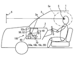
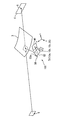
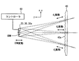
- FIG. 1 It is a schematic diagram which shows the mounting state to the vehicle of the HUD apparatus in 1st Embodiment. It is a mimetic diagram showing a schematic structure of a HUD device in a 1st embodiment.
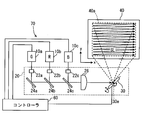
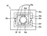
- the schematic diagram which shows the oscillator, projection optical system, and screen member in 1st Embodiment. It is a top view which expands and shows the scanning mirror in a 1st embodiment typically. It is a schematic diagram which shows the relationship between the scanning mirror in 1st Embodiment, and its screen member. It is a schematic diagram for demonstrating the focal distance of the projection optical system in 1st, 3rd embodiment. It is a top view which shows partially the screen member in 1st Embodiment.
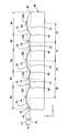
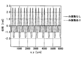
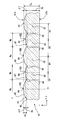
- FIG. 8 is a diagram partially showing the screen member according to the first embodiment, and is a schematic cross-sectional view corresponding to a cross section taken along line VIIIx-VIIIx and a cross section taken along line VIIIy-VIIIy in FIG. 7. It is a schematic diagram for demonstrating a speckle pattern. It is a figure corresponding to FIG. 5 in a comparative example. It is a schematic diagram which shows the result of having simulated the phase distribution of the vibration component when the focal distance of a projection optical system vibrates, and when not vibrating. It is a schematic diagram for demonstrating magnitude
- DELTA magnitude
- FIG. 8 is a diagram corresponding to FIG. 7 in Modification 1. It is a figure corresponding to FIG. 7 in the modification 2.
- FIG. 10 is a diagram corresponding to FIG. 7 in an example of modification example 4; It is a figure corresponding to FIG. 7 in an example different from FIG. 20 of the modification 4.
- FIG. 10 is a diagram corresponding to FIG. 7 in an example of modification example 4; It is a figure corresponding to FIG. 7 in an example different from FIG. 20 of the modification 4.
- the head-up display device 100 As shown in FIG. 1, the head-up display device 100 according to the first embodiment of the present disclosure is mounted on a vehicle 1 that is a kind of moving body and is housed in an instrument panel 2.
- the HUD device 100 projects an image on a windshield 3 as a projection member of the vehicle 1.
- the HUD device 100 displays a virtual image so that the image can be visually recognized by the occupant of the vehicle 1 in the visual recognition area 4. That is, the image light reflected by the windshield 3 reaches the eyepoint 5 of the passenger in the vehicle 1 and the passenger perceives the light.
- the occupant can recognize various images displayed as the virtual image 6. Examples of various information displayed as the virtual image 6 include vehicle state values such as vehicle speed and fuel remaining amount, or vehicle information such as road information and visibility assistance information.
- the surface on the indoor side forms a projection surface 3a on which an image is projected in a curved concave shape or a flat planar shape.
- the windshield 3 may have an angle difference for overlapping the virtual image 6 formed by reflecting each surface between the indoor side surface and the outdoor side surface.
- the windshield 3 may be provided with a vapor deposition film or a film in order to suppress the luminance of the virtual image 6 due to the reflection of the outdoor surface.
- a combiner separate from the vehicle 1 may be installed in the vehicle 1 and an image may be projected onto the combiner.
- the visual recognition area 4 is an area in which an image as the virtual image 6 is visible as shown in FIG.
- the visual recognition area 4 is set in consideration of an eyelip 5a, which is a space area in which an eyepoint 5 of a passenger seated in the seat can exist.
- the eyesight 5a is taken into consideration so that a sufficiently wide viewing area 4 is set, so that the occupant can image the virtual image 6 even if the occupant's eyepoint 5 moves slightly. Can be visually recognized.
- the HUD device 100 includes a controller 60, a plurality of oscillators 10a, 10b, and 10c, a projection optical system 20, a screen member 40, and an enlargement optical system 50, as shown in FIGS.
- a laser scanner 70 is constituted by the three oscillators 10 a to 10 c and the projection optical system 20.
- the controller 60 is a control circuit composed of an arithmetic processing unit and a memory. As shown in FIGS. 1 and 3 and the like, the controller 60 is electrically connected to the oscillators 10a to 10c, the scanning mirror 30 of the projection optical system 20, the concave mirror 52 of the magnifying optical system 50, and the like.
- the three oscillators 10a to 10c oscillate laser beams having different hues in the form of light beams.
- the oscillator 10a oscillates a green laser beam having a peak wavelength of 560 nm, for example.
- the oscillator 10b oscillates a red laser beam having a peak wavelength of 635 nm, for example.
- the oscillator 10c oscillates a blue laser beam having a peak wavelength of 450 nm, for example.
- each of the oscillators 10a to 10c is electrically connected to the controller 60.
- Each of the oscillators 10a to 10c oscillates a laser beam in accordance with an electric signal from the controller 60.
- Various colors can be reproduced by adding and mixing the three colors of laser beams emitted from the oscillators 10a to 10c.
- the laser beams emitted from the oscillators 10a to 10c propagate toward the shaping lenses 22a, 22b, and 22c of the projection optical system 20, respectively.
- the projection optical system 20 is an optical system that projects a laser beam onto the screen member 40.
- the projection optical system 20 of the first embodiment includes three shaping lenses 22a to 22c, three dichroic filters 24a, 24b, and 24c, a condensing lens 26, and a scanning mirror of a micro electro mechanical system (MEMS). 30.
- MEMS micro electro mechanical system
- the three shaping lenses 22a to 22c are arranged at intervals of, for example, 5 mm in the propagation direction of each laser beam with respect to the corresponding oscillators 10a to 10c.
- Each shaping lens 22a-c shapes the laser beam by refracting the laser beam from the corresponding oscillator 10a-c.
- the three dichroic filters 24a to 24c are arranged at intervals of, for example, 4 mm in the propagation direction of each laser beam with respect to the corresponding shaping lenses 22a to 22c, respectively.
- Each of the dichroic filters 24a to 24c reflects a laser beam having a specific wavelength and reflects a laser beam having another wavelength among the laser beams transmitted through the corresponding shaping lenses 22a to 22c.
- the dichroic filter 24a corresponding to the shaping lens 22a reflects the green laser beam.
- the dichroic filter 24b corresponding to the shaping lens 22b reflects the red laser beam and transmits the other laser beam.
- the dichroic filter 24c corresponding to the shaping lens 22c reflects the blue laser beam and transmits the other laser beam.
- the dichroic filter 24b is arranged with an interval of 6 mm, for example. Further, the dichroic filter 24c is disposed, for example, at an interval of 6 mm in the propagation direction of the red laser beam after reflection by the dichroic filter 24b.
- the green laser beam reflected by the dichroic filter 24a is mixed with the red laser beam reflected by the dichroic filter 24b. Further, the green laser beam and the red laser beam are transmitted through the dichroic filter 24c and mixed with the blue laser beam after being reflected by the dichroic filter 24c. In this way, three colors of laser light can be added and mixed.
- the condenser lenses 26 are arranged with an interval of 4 mm, for example.
- the condenser lens 26 is a plano-convex lens in which the dichroic filter 24c side is formed in a planar shape and the scanning mirror 30 side is formed in a convex shape.
- the condensing lens 26 condenses the laser beam from the dichroic filters 24a to 24c.
- the laser beam transmitted through the condenser lens 26 propagates toward the scanning mirror 30.
- the scanning mirror 30 is a MEMS mirror that functions as a scanning unit that temporally scans the projection direction of the laser beam.
- the scanning mirror 30 includes an outer frame 30a, an inner frame 30b, a horizontal twist bar 30c, a vertical twist bar 30d, a reflective surface 30e, and a transmission part 30g.
- the outer frame 30a is a rectangular frame positioned outside the scanning mirror 30, and the inner frame 30b is a rectangular frame positioned between the outer frame and the reflecting surface.
- Two horizontal torsion bars 30c along the direction x are formed between the outer frame 30a and the inner frame 30b.
- two vertical torsion bars 30d along the direction y are formed between the inner frame 30b and the reflecting surface 30e.
- the reflection surface 30e formed at the center of the scanning mirror 30 is formed in a thin film shape by metal deposition of aluminum or the like so as to reflect the laser beam.
- a possible transmission part 30g is formed in an opening shape.
- Such a scanning mirror 30 is electrically connected to the controller 60, and the horizontal twist bar 30c and the vertical twist bar 30d are separately twisted according to the scan signal. By these twists, the direction of the reflection surface 30e can be changed, and the projection direction of the laser beam from the condenser lens 26 can be temporally scanned.
- FIG. 5 schematically shows the focal length FL of the projection optical system 20 in the present embodiment between the principal point PRP and the focal point FCP when a parallel light beam is incident from the oscillators 10a to 10c. The length along the optical axis in between.
- the laser beam from the condenser lens 26 is incident with the spot size SS larger than the size SR of the reflecting surface 30e at the time of incidence on the scanning mirror 30, as shown in FIG.
- the beam incident on the outside of the outer edge 30f of the reflecting surface 30e is transmitted through the scanning mirror 30 by the transmission unit 30g and emitted outside the projection optical system 20. That is, the scanning mirror 30 of this embodiment also functions as a stop.
- the laser beam reflected by the reflecting surface 30e is projected toward the projection area 40a of the screen member 40 while temporally scanning the projection direction.
- the projection direction of the laser beam is sequentially scanned in the arrow direction of FIG. 3 along the plurality of scanning lines SL.
- the position where the laser beam is projected moves in the projection area 40a, and the laser beam is intermittently pulse-projected, whereby an image is drawn and formed.
- the image drawn in the projection area 40a is drawn and formed in the projection area 40a at a frame rate of 60 frames per second, for example, as an image having 480 pixels in the direction x and 240 pixels in the direction y.
- the screen member 40 in the first embodiment is a reflective screen formed by depositing aluminum on the surface of a base material made of synthetic resin or glass.
- the screen member 40 has irregularities in the projection area 40a.
- the screen member 40 is formed as a micromirror array having a plurality of optical elements 42 that are arranged in a lattice pattern in the projection region 40a and have irregularities.
- Each optical element 42 has a mirror-like curved surface 43 exhibiting a convex curvature as a common curved form on the outer surface of the screen member 40.
- the curved surface 43 has a radius of curvature CR, protrudes to the side facing the scanning mirror 30 of the projection optical system 20 in the direction z orthogonal to the directions x and y, and has the most protruding point as the surface vertex 44.
- the optical elements 42 adjacent to each other in the directions x and y form the boundary 46 therebetween by overlapping the outer edges (contours) of the curved surfaces 43 with each other.
- the depth which is the amount of deviation from the reference surface vertex 44 to the boundary 46 (indicated by the inflection point in the cross section of FIG. 8) in the direction z, is optical.
- the amount of sag in the element 42 is defined. 7 and 8, only a part of the reference numerals are shown for easy understanding.
- the height at the surface vertex 44 of the curved surface 43 is different between adjacent optical elements 42.
- different sag amounts between adjacent optical elements 42 are set in the entire projection area 40a.
- the sag amount two types of sag amounts Sa and Sb are set, and the optical element 42 having the large sag amount Sa and the optical element 42 having the small sag amount are alternately arranged in any direction x and y.
- a large element width Wa and a small element width Wb are set as the element width of the optical element 42.
- the peak pitch PP corresponds to the distance between the surface vertices 44 of the adjacent optical elements 42.
- a step in the direction z is formed according to the difference ⁇ S between the sag amounts Sa and Sb, that is, (Sa ⁇ Sb). Further, also in one optical element 42, the height in the direction z differs depending on the location due to the curved surface 43 exhibiting the convex curvature having the curvature radius CR. As a result, irregularities are formed on the screen member 40 in the projection region 40a.
- the screen member 40 reflects the image light as the laser light beam diffused through the uneven curved surface 43 toward the concave mirror 52 of the magnifying optical system 50.
- the magnifying optical system 50 is an optical system that magnifies and projects an image onto the windshield 3 and guides the light of the image to the viewing area 4.
- the magnifying optical system 50 in the present embodiment includes the concave mirror 52, but may be configured by additionally adding a plane mirror having a planar reflecting surface, a magnifying lens, or the like.
- the concave mirror 52 is formed by evaporating aluminum as the reflecting surface 52a on the surface of a base material made of synthetic resin or glass.
- the reflecting surface 52a is formed in a smooth curved surface as a concave surface in which the center of the concave mirror 52 is recessed.
- the concave mirror 52 reflects the image light toward the windshield 3. Thus, the light of the image reflected by the windshield 3 reaches the visual recognition area 4.
- the concave mirror 52 is driven to swing in accordance with a swing signal from the electrically connected controller 60. As the concave mirror 52 swings in this way, the imaging position of the virtual image 6 and the visual recognition area 4 move up and down.
- the visual recognition area 4 and the image visually recognized as the virtual image 6 by the HUD device 100 will be described in detail below.
- the screen member 40 (or screen SCR) is arranged along the xy plane composed of the x-axis and the y-axis, and the laser beam is directed toward the negative direction of the z-axis in the screen member 40 (or screen SCR). It will be described as being projected on the screen.
- the wavefront of a light beam after diffusion on a predetermined screen SCR is A (x, y, 0), and the wavefront at a point P (x, y, z) at which the wavefront A is observed.
- U (P) can be expressed as the following mathematical expression 3 according to Kirchhoff-Fresnel diffraction formula.
- k is the wave number
- q is the distance from the point S1 ( ⁇ , ⁇ , 0) to the point P (x, y, z).
- Equation 5 Equation 5
- the observed wavefront U (P) is formulated in a form in which the vibration component F (x, y, d, k) is convolved with the wavefront A (x, y, 0) after passing through the screen SCR. It becomes. It can be seen that the wavefront U (P) changes when the coordinates (x, y) of the screen SCR are moved by the vibration component F (x, y, d, k) shown in Equation 7.
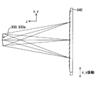
- the coordinates (x, y) of the screen member 940 on which the laser beam is projected from the scanning mirror 930 having the reflection surface 930e having a constant curvature radius are temporally vibrated.
- the vibration component F (x, y, d, k) changes due to the vibration of the screen member 940, so the speckle pattern changes.
- moving the screen member 40 having a higher space occupancy rate than the scanning mirror 30 or the like in the HUD device 100 remains a concern, considering that it is mounted in a limited space of the vehicle 1.
- the distance d of Equation 7 is considered to correspond to the defocus amount dS of the laser beam with respect to the screen member 40. It is also conceivable that the speckle pattern changes with time as a wavefront change by vibrating the defocus amount dS with time. And it becomes possible to make a passenger
- FIG. 5 the arrangement of the scanning mirror 30 and the screen member 40 is schematically shown.
- the laser beam is shown in three directions, but each moment when the projection direction of the laser beam is scanned is schematically shown in one drawing.
- the projection direction of the laser beam is indicated by a thin solid line.
- FIG. 11 plots the spatial distribution of phases in the vibration component F (x, y, dS, k) of Formula 7.
- the defocus amount dS is constant (solid line graph)
- the phase changes in space, and the luminance distribution corresponding to the spatial distribution of the phase is obtained in the visually recognized image.
- the defocus amount dS vibrates with time as in the present embodiment (a one-dot chain line graph)
- the spatial change of the phase is suppressed, and the luminance distribution corresponding to the spatial distribution of the phase in the visually recognized image
- the radius of curvature CRM of the reflecting surface 30e of the scanning mirror 30 is temporally changed by the drive signal of the controller 60, so that the focal length FL of the projection optical system 20 is temporally changed. It comes to vibrate. Due to the temporal vibration of the focal length FL of the projection optical system 20, the defocus amount dS of the laser beam with respect to the screen member 40 vibrates in time.
- the radius of the area (hereinafter referred to as the smoothing area) where the speckle pattern is smoothed by the vibration of the defocus amount dS is defined as R.
- the phase of the vibration component F (x, y, dS, k) in Equation 7 may be set in the range of ⁇ 2 ⁇ to + 2 ⁇ . Therefore, the defocus amount dS is preferably set in the range of the following formula 8 as a mathematical expression.
- the spot radius ⁇ of the laser beam in the projection area 40a of the screen member 40 is approximated by the following equation (9) from the Rayleigh equation using the defocus amount dS.
- NA is defined as the numerical aperture of the optical system that generates the laser beam, that is, the oscillators 10 a to 10 c and the projection optical system 20 that constitute the laser scanner 70.
- ⁇ is the wavelength of the laser beam.
- the size on the screen member corresponding to the visibility limit of the spot radius ⁇ on the screen member 40 of the laser beam is defined as ⁇ . If the following formula 10 shown as a mathematical expression based on ⁇ > ⁇ holds, the occupant cannot visually recognize the spot of the laser beam corresponding to one pixel in the visual recognition area 4. Further, when the formula 10 is transformed, the following formula 11 is obtained as a mathematical formula.
- Equation 12 expressed as a mathematical formula that satisfies ⁇ ⁇ R is solved. From Equation 12, the following Equation 13 is obtained as a mathematical expression.
- the numerical aperture NA is set so as to satisfy Expression 13.
- the MEMS scanning mirror 30 serving as a scanning unit is used as a diaphragm. Specifically, Expression 13 is satisfied even when the defocus amount dS takes the maximum value under the condition that the size SR of the reflecting surface 30e is smaller than the spot size SS when the laser beam is incident on the reflecting surface 30e.
- the size of the reflecting surface is set so as to.
- ⁇ is determined by the optical path until the light of the image reaches the visual recognition area 4, that is, the arrangement of the magnifying optical system 50 and the windshield 3, and the like.
- the distance from the eye point 5 to the virtual image 6 in the visual recognition area 4 is LV
- the imaging magnification of the imaging system from the screen member 40 to the visual recognition area 4 is MV
- human resolution RE is assumed.
- the radius ⁇ is expressed as a mathematical expression 14 below.
- Equation 15 is obtained as an equation.
- the absolute value of the defocus amount dS only needs to be set to 2237 ⁇ m or less.
- the projection is performed so as to be in such a range.
- the focal length FL of the optical system 20 vibrates with time.
- the focal length FL of the projection optical system 20 oscillates periodically, and the oscillation cycle is set so as to deviate from the frame rate in the operation of the scanning mirror 30 described above.
- the vibration period is set to a value other than an integral multiple of the frame rate, for example, set to 1/70 seconds.
- the speckle pattern is temporally averaged by the vibration of the focal length FL of the projection optical system 20 set as described above.
- the laser beam reflected by the projection region 40a of the screen member 40 is diffused as image light at a diffusion angle corresponding to the radius of curvature CRE set on the curved surface 43 of each optical element 42, and one pixel.
- the light corresponding to each reaches the viewing area 4 with a width.
- the laser beam scanned by the scanning mirror 30 causes interference after diffusion due to the grid-like arrangement of the optical elements 42 in the viewing area 4 as image light.
- the optical path difference ⁇ L of the light that interferes by being emitted from the curved surface 43 of the surface of each adjacent optical element 42 at the exit angle ⁇ as a reflection angle is generated as shown in FIG. 13, for example.
- the optical path difference ⁇ L is expressed by the following formulas 16 and 17 using a peak pitch PP sufficiently larger than ⁇ S under approximation of sin ⁇ [rad].
- Expression 16 is established between one optical element 42 of the large sag amount Sa and the optical element 42 of the small sag amount Sb adjacent to one side (for example, the right side in FIG. 13).
- Expression 17 is established between one optical element 42 of the large sag amount Sa and the optical element 42 of the small sag amount Sb adjacent to the opposite side (for example, the left side in FIG. 13).
- the angle difference ⁇ of the emission angle ⁇ at which the optical path difference ⁇ L changes by the wavelength ⁇ that is, the angle difference ⁇ of the emission angle ⁇ at which the order of the diffraction peak generated by the interference between lights changes by 1
- the following formula 18 is expressed as a mathematical formula using the peak pitch PP.
- the intensity distribution corresponds to the angle difference ⁇ of the emission angle ⁇ .
- the diffraction peak generated by one optical element 42 of the large sag amount Sa and the one-side adjacent element 42 of the small sag amount Sb according to Equations 16 and 18 is 2 ⁇ ⁇ S ⁇ ⁇ with respect to 0.
- An emission angle ⁇ every ⁇ ⁇ is generated at the center from the 0th-order diffraction angle ⁇ 0 shifted by / ⁇ (solid line graph).
- the diffraction peak generated by one optical element 42 of the large sag amount Sa and the opposite adjacent element 42 of the small sag amount Sb according to the equations 17 and 18 is ⁇ 2 ⁇ ⁇ S ⁇ ⁇ / From the 0th-order diffraction angle ⁇ 0 shifted by ⁇ , an emission angle ⁇ every ⁇ ⁇ is generated at the center (one-dot chain line graph).
- the diffraction peak of the diffracted light generated between one optical element 42 and the adjacent elements 42 on both sides is centered on different exit angles ⁇ . Occur in each other. As a result of this shifting action, it is difficult to increase the intensity of diffraction peaks generated by one optical element 42 between adjacent elements 42 on both sides thereof.
- the exit angle ⁇ corresponding to each diffraction peak.
- the intensity difference ⁇ I is small between ( ⁇ 0 from each of ⁇ 0 and ⁇ 0) and the emission angle ⁇ therebetween.
- the setting of the sag amount difference ⁇ S means that the difference in light intensity is reduced at each location in the viewing area 4.
- the controller 60 constitutes a “variable focal point”.
- the oscillators 10 a to 10 c that oscillate a laser beam, the screen member 40 that has projections and depressions and forms an image, the laser beam is projected onto the screen member 40, and the focal length is determined by the drive signal of the controller 60.
- a projection optical system 20 in which FL is temporally vibrated and an enlargement optical system 50 that guides light of the image to the visual recognition region 4 by enlarging the image and projecting the image onto the windshield 3 are provided.
- the focal length FL of the projection optical system 20 oscillates in the projection direction by the drive signal of the controller 60
- the laser beam is a screen member having irregularities as light in which the speckle pattern is temporally averaged. Projected on.
- an HUD device that secures an appropriate visual recognition area 4, suppresses luminance unevenness of the visually recognized image, and easily secures a space for mounting the HUD device that displays an image of a size that is easy to visually recognize in the vehicle 1. 100 can be provided.
- the projection optical system 20 temporally scans the projection direction of the laser beam, and the oscillation period in which the focal length FL periodically oscillates from the frame rate of this scanning.
- an image can be easily formed on the screen member 40 by temporal scanning of the laser beam, and the influence of the speckle pattern can be easily suppressed in a small smoothed region.
- the speckle pattern is reliably projected onto the screen member 40 having the unevenness as light that is temporally averaged by the vibration period that deviates from the frame rate.
- the light of the image formed by the screen member 40 is diffused by the unevenness and is guided to the viewing area while the image is enlarged by the magnifying optical system 50. Therefore, it is possible to provide the HUD device 100 that secures an appropriate visual recognition area 4, suppresses luminance unevenness of the visually recognized image, and easily secures a space.
- the direction of the reflecting surface 30e that reflects the laser beam is changed in the scanning mirror 30 of the micro electro mechanical system by the scanning signal of the controller 60. Further, the controller 60 temporally varies the curvature radius CRM of the reflecting surface 30e according to the drive signal. According to this, since the reflecting surface 30e varies with time, the scanning mirror 30 and the vibration of the focal length FL can be realized by a common member. Furthermore, since the positional relationship between the reflecting surface 30e and the projection location of the screen member is maintained, fluctuations in the angle of view of the image can be suppressed.
- the MEMS scanning mirror 30 forms the transmission part 30g that transmits the laser beam around the reflection surface 30e.
- the numerical aperture NA of the oscillators 10a to 10c and the projection optical system 20 can be easily set using the transmission part 30g formed in the scanning mirror 30 of the MEMS. Therefore, an HUD device that secures an appropriate visual recognition area 4, suppresses luminance unevenness of the visually recognized image, and easily secures a space for mounting the HUD device that displays an image of a size that is easy to visually recognize in the vehicle 1. 100 can be provided.
- the screen member 40 includes a plurality of optical elements 42 arranged in a lattice pattern in the projection region 40a, and each optical element 42 has a common curved form of convex curvature and concave curvature. Is formed on the surface of the screen member 40, and the laser beam is diffused through the curved surface 43. According to this, it is possible to set the arrangement of the optical elements 42 and the curvature radius CRE so that an appropriate visual recognition area 4 can be obtained while suppressing the influence of the speckle pattern by the mirror-like curved surface 43.
- the height at the surface vertex 44 of the curved surface 43 is different between adjacent optical elements 42. According to this, the diffraction peaks of the diffracted light generated by one optical element 42 between adjacent optical elements 42 on both sides thereof are shifted from each other. By utilizing this shifting action, it is possible to suppress luminance unevenness that occurs between each part of the visual recognition area 4, so that a more appropriate visual recognition area 4 can be ensured.
- the spot radius ⁇ is not visually recognized even when the visually recognized image is enlarged.
- the luminance unevenness of the displayed image becomes inconspicuous.
- the numerical aperture NA is 0.018 or less. According to this, even when the visible image is enlarged when the oscillator 10a that oscillates the green laser beam having the highest visible sensitivity is used in the HUD device 100 with the standard imaging magnification MV, The spot radius ⁇ is not visually recognized, and the luminance unevenness of the visually recognized image becomes inconspicuous.
- the absolute value of the defocus amount dS is set so that the mathematical expression 15 is satisfied. According to this, while the focal length FL of the projection optical system 20 oscillates in the projection direction, the laser beam is projected onto the screen member 40 having irregularities as light averaged over time.
- defocusing in a range where the spot radius ⁇ is not visually recognized increases the effect of suppressing luminance unevenness of the visually recognized image.
- the absolute value of the defocus amount dS is 2237 ⁇ m or less. According to this, when the oscillator 10a that oscillates the green laser beam having the highest visible sensitivity is used in the HUD device 100 having the standard imaging magnification MV, the spot radius ⁇ is not visually recognized. By defocusing the range, the effect of suppressing luminance unevenness of the visually recognized image is enhanced.
- the second embodiment of the present disclosure is a modification of the first embodiment.
- the second embodiment will be described with a focus on differences from the first embodiment.
- the screen member 240 in the second embodiment is a reflective screen formed mainly of synthetic resin, for example.
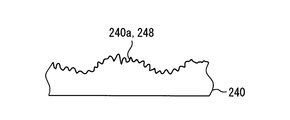
- the screen member 240 has a diffusion surface 248 that is uneven by projections in the projection region 240a. That is, unevenness is formed in the projection region 240a.
- the textured fine irregularities on the diffusion surface 248 are randomly formed by, for example, etching the surface, but may be formed by applying the coating material to the surface or the like.
- Such a screen member 240 reflects the image light diffused through the uneven diffusing surface 248 toward the concave mirror 52 of the magnifying optical system 50.
- the focal length FL of the projection optical system 20 oscillates temporally by the drive signal from the controller 60 as in the first embodiment. Therefore, it is possible to achieve the operational effects according to the first embodiment.
- the screen member 240 has the diffusion surface 248 that is uneven by the embossing in the projection region 240 a, and diffuses the laser light beam through the diffusion surface 248. According to this, the appropriate visual recognition area
- the third embodiment of the present disclosure is a modification of the first embodiment.
- the third embodiment will be described with a focus on differences from the first embodiment.
- the projection optical system 320 of the third embodiment is an optical system that projects a laser beam onto the screen member 40, as in the first embodiment.
- the projection optical system 320 of the third embodiment includes three shaping lenses 22a to 22c, three dichroic filters 24a to 24c, a condensing lens 26, a variable focus lens 328, and a MEMS scanning mirror 330.
- the three shaping lenses 22a to 22c, the three dichroic filters 24a to 24c, and the condenser lens 26 are the same as in the first embodiment.
- the laser light beam transmitted through the condenser lens 26 propagates toward the variable focus lens 328.
- controller 360 of the third embodiment is electrically connected to the variable focus lens 328 in addition to the oscillators 10a to 10c, the scanning mirror 330, and the like.
- the variable focus lens 328 is a liquid lens in which a boundary surface 328c between the high conductive liquid 328a and the low conductive liquid 328b is changed by a drive signal from the controller 360. Specifically, the variable focus lens 328 seals an aqueous solution as the high conductive liquid 328a and an oil as the low conductive liquid 328b having different refractive indexes in a cylindrical container 328d. When a voltage corresponding to the drive signal from the controller 360 is applied to the variable focus lens 328, the radius of curvature CRB of the boundary surface 328c between the high conductive liquid 328a and the low conductive liquid 328b varies.
- the laser beam is refracted according to the lens focal length that varies according to the radius of curvature CRB of the boundary surface 328c.
- the focal length FL (see also FIG. 6) of the projection optical system 20 can be vibrated in time.
- the scanning mirror 330 is a scanning mirror that functions as a scanning unit that temporally scans the projection direction of the laser beam, as in the first embodiment.
- the scanning mirror 330 of the third embodiment has a reflecting surface 330e formed in a flat shape and does not have a function of changing the radius of curvature.
- the focal length FL of the projection optical system 320 oscillates temporally by the drive signal from the controller 360. Therefore, it is possible to achieve the operational effects according to the first embodiment.
- variable focus lens 328 whose power fluctuates is used for the vibration of the focal length FL of the projection optical system 320. According to this, the temporal vibration of the focal length FL of the projection optical system 320 can be easily realized. Therefore, it is possible to secure an appropriate visual recognition area 4 and suppress luminance unevenness of the visually recognized image.
- the controller 360 constitutes a “variable focus unit”.
- each optical element 42 only needs to exhibit a common curved form of concave curved surface and convex curved surface.
- each optical element 42 may have a mirror-like curved surface 43 exhibiting a concave curvature as a curved form on the outer surface of the screen member 40.
- different curvature radii CREa and CREb may be set between adjacent optical elements 42, and the same element width W is set. May be.
- the height of the curved surface 43 at the surface vertex 44 of the adjacent optical elements 42 may substantially match.
- the screen member 40 is a transmissive screen made of translucent synthetic resin or glass or the like, and in the projection region 40 a. It may be formed as a microlens array having a plurality of optical elements 42 that are arranged in a lattice pattern to form irregularities.
- a curved surface 43 is formed on the incident-side outer surface 47a on the scanning mirror 30 side, and the thickness Ta at the surface apex 44 of the optical element 42 with the large sag amount Sa and the optical element with the small sag amount Sb.
- the thickness Tb at the surface vertex 44 of 42 is set, and the difference in thickness is ⁇ T.
- a curved surface 43 is formed on the exit-side outer surface 47b on the magnifying optical system 50 side.
- the screen member 240 is a transmission type screen made of a light-transmitting synthetic resin or glass or the like. It may have a diffusing surface 248 that is uneven by embossing.
- the projection optical system 20 may not be configured to transmit the laser beam around the reflection surface 30e of the scanning mirror 30.
- a separate aperture may be provided in the projection optical system 20, and the numerical aperture NA may be controlled by the oscillators 10a to 10c.
- the numerical aperture NA may not be set so as to satisfy the above-described formula 13.
- the defocus amount dS may not be set so as to satisfy the above-described Expression 15.
- the oscillators 10a to 10c may oscillate laser beams having other wavelengths as long as they are visible light, and one color, two colors, or four colors or more.
- the laser beam may be used to form an image.
- the focal length FL of the projection optical system 20 may not periodically oscillate as long as it oscillates in time by the drive signal of the controller 60.
- the focal length may vibrate randomly.
- variable focus lens 328 a liquid crystal lens whose refractive index varies with voltage may be used as the variable focus lens 328.
- the “variable focus portion” may be configured by a device other than the controller 60 electrically connected to the optical element of the projection optical system 20.
- the present disclosure may be applied to various moving bodies (transportation equipment) such as a ship other than the vehicle 1 or an airplane.
Landscapes
- Physics & Mathematics (AREA)
- General Physics & Mathematics (AREA)
- Optics & Photonics (AREA)
- Engineering & Computer Science (AREA)
- Chemical & Material Sciences (AREA)
- Combustion & Propulsion (AREA)
- Transportation (AREA)
- Mechanical Engineering (AREA)
- Instrument Panels (AREA)
Abstract
車両に搭載され、ウインドシールドに画像を投影することにより、画像を視認領域において乗員により視認可能に虚像表示するHUD装置は、レーザ光束を発振する発振器と、レーザ光束の投射により画像が形成される投射領域(40a)に凹凸を有するスクリーン部材(40)と、レーザ光束をスクリーン部材(40)に投射する投射光学系(20)と、画像を拡大してウインドシールドに投影し、画像の光を視認領域に導く拡大光学系と、投射光学系(20)の焦点距離を時間的に振動させるコントローラ(60)とを備える。これにより、適切な視認領域を確保し、視認される画像の輝度ムラを抑制し、スペースの確保が容易となる。
Description
本出願は、当該開示内容が参照によって本出願に組み込まれた、2014年7月30日に出願された日本特許出願2014-155482号を基にしている。
本開示は、移動体に搭載され、投影部材に画像を投影することにより、画像を視認領域において乗員により視認可能に虚像表示するヘッドアップディスプレイ装置(以下、HUD装置を略称とする)に関する。
従来、移動体に搭載され、投影部材に画像を投影することにより、画像を視認領域において乗員により視認可能に虚像表示するHUD装置が知られている。特許文献1に開示のHUD装置では、レーザ光束を発振する発振器と、凹凸を有し、画像を形成するスクリーン部材と、レーザ光束をスクリーン部材に投射し、投射光学系と、画像を拡大して投影領域に投影し、画像の光を視認領域に導く拡大光学系とを備えている。
レーザ光束を発振する発振器を備えるHUD装置において、凹凸のないスクリーン部材を用いると、視認領域の広さを確保できない。しかし一方で、特許文献1の凹凸を有するスクリーン部材を用いると、視認領域の広さを得られるが、レーザ光束がスクリーン部材に投射されることによってスペックルパターンが発生し、視認される画像に輝度ムラが生ずる恐れがある。
さらに、画像の光を拡大して視認領域に導く拡大光学系を用いると、スペックルパターンも拡大されて、輝度ムラはより顕著に視認されることとなってしまう。一方で画像の光を拡大しないで視認領域に導く光学系を用いると、視認される画像のサイズが小さくなる若しくはサイズの大きなスクリーン部材を用いなければならず、視認しやすいサイズの画像を虚像表示するHUD装置を移動体に搭載するためのスペースの確保が困難となる。
本開示は、以上説明した点に鑑みてなされたものであって、その目的は、適切な視認領域を確保し、視認される画像の輝度ムラを抑制し、スペースの確保が容易なHUD装置を提供することにある。
本開示は、移動体に搭載され、投影部材に画像を投影することにより、画像を視認領域において乗員により視認可能に虚像表示するヘッドアップディスプレイ装置であって、
レーザ光束を発振する発振器と、
レーザ光束の投射により画像が形成される投射領域に凹凸を有するスクリーン部材と、
レーザ光束をスクリーン部材に投射する投射光学系と、
画像を拡大して投影部材に投影し、画像の光を視認領域に導く拡大光学系と、
投射光学系の焦点距離を時間的に振動させる可変焦点部とを備える。
レーザ光束を発振する発振器と、
レーザ光束の投射により画像が形成される投射領域に凹凸を有するスクリーン部材と、
レーザ光束をスクリーン部材に投射する投射光学系と、
画像を拡大して投影部材に投影し、画像の光を視認領域に導く拡大光学系と、
投射光学系の焦点距離を時間的に振動させる可変焦点部とを備える。
このような開示によると、レーザ光束を発振する発振器と、凹凸を有し、画像を形成するスクリーン部材と、レーザ光束をスクリーン部材に投射し、可変焦点部によって焦点距離(の大きさ)が時間的に振動される投射光学系と、画像を拡大して投影部材に投影することで、画像の光を視認領域に導く拡大光学系とを備える。これによれば、可変焦点部により投射光学系の焦点距離が投射方向に振動しながら、レーザ光束は、スペックルパターンが時間的に平均化された光として、凹凸を有するスクリーン部材に投射される。
そして、スクリーン部材により形成される画像の光は、凹凸により拡散されて、拡大光学系により画像を拡大されながら視認領域に導かれる。したがって、適切な視認領域を確保し、視認される画像の輝度ムラを抑制し、視認しやすいサイズの画像を虚像表示するHUD装置を移動体に搭載するためのスペースの確保が容易なHUD装置を提供することができる。
以下、本開示の複数の実施形態を図面に基づいて説明する。なお、各実施形態において対応する構成要素には同一の符号を付すことにより、重複する説明を省略する場合がある。各実施形態において構成の一部分のみを説明している場合、当該構成の他の部分については、先行して説明した他の実施形態の構成を適用することができる。また、各実施形態の説明において明示している構成の組み合わせばかりではなく、特に組み合わせに支障が生じなければ、明示していなくても複数の実施形態の構成同士を部分的に組み合せることができる。
(第1実施形態)
図1に示すように、本開示の第1実施形態によるヘッドアップディスプレイ装置100は、移動体の一種である車両1に搭載され、インストルメントパネル2内に収容されている。HUD装置100は、車両1の投影部材としてのウインドシールド3に画像を投影する。これにより、HUD装置100は、画像を視認領域4において車両1の乗員により視認可能に虚像表示する。すなわち、ウインドシールド3に反射される画像の光が、車両1の室内の乗員のアイポイント5に到達し、乗員が当該光を知覚する。そして、乗員は、虚像6として表示される各種画像を認識することができる。虚像6として表示される各種情報としては、例えば、車速、燃料残量等の車両状態値、又は道路情報、視界補助情報等の車両情報が挙げられる。
図1に示すように、本開示の第1実施形態によるヘッドアップディスプレイ装置100は、移動体の一種である車両1に搭載され、インストルメントパネル2内に収容されている。HUD装置100は、車両1の投影部材としてのウインドシールド3に画像を投影する。これにより、HUD装置100は、画像を視認領域4において車両1の乗員により視認可能に虚像表示する。すなわち、ウインドシールド3に反射される画像の光が、車両1の室内の乗員のアイポイント5に到達し、乗員が当該光を知覚する。そして、乗員は、虚像6として表示される各種画像を認識することができる。虚像6として表示される各種情報としては、例えば、車速、燃料残量等の車両状態値、又は道路情報、視界補助情報等の車両情報が挙げられる。
車両1のウインドシールド3において、室内側の面は、画像が投影される投影面3aを、湾曲する凹面状又は平坦な平面状等に形成している。また、ウインドシールド3は、室内側の面と室外側の面とで、各面を反射してできる虚像6を重ねるための角度差を有するものであってもよい。あるいは、ウインドシールド3は、室外側の面の反射による虚像6の輝度を抑制するために蒸着膜ないしはフィルム等を設けたものであってもよい。さらに、投影部材として、ウインドシールド3の代わりに、車両1と別体となっているコンバイナを車両1内に設置して、当該コンバイナに画像を投影するものであってもよい。
視認領域4は、図2に示すように、虚像6としての画像が視認可能となる領域である。座席に着席した乗員のアイポイント5が存在可能な空間領域であるアイリプス5aを考慮して、視認領域4が設定されている。例えば、本実施形態のように、アイリプス5aを考慮して、十分な広さの視認領域4が設定されることで、乗員のアイポイント5が多少動いても、乗員は、虚像6としての画像を視認可能となる。
HUD装置100は、図1,2に示すように、コントローラ60、複数の発振器10a,10b,10c、投射光学系20、スクリーン部材40、及び拡大光学系50を備えている。ここで、3つの発振器10a~c、投射光学系20により、レーザスキャナ70が構成されている。
コントローラ60は、演算処理装置及びメモリ等から構成される制御回路である。図1,3等に示すように、コントローラ60は、各発振器10a~c、投射光学系20の走査ミラー30、拡大光学系50の凹面ミラー52等と電気的に接続されている。
3つの発振器10a~cは、図3に示すように、互いに異なる色相のレーザ光を光束状に発振する。発振器10aは、例えばピーク波長が560nmである緑色のレーザ光束を発振するようになっている。発振器10bは、例えばピーク波長が635nmである赤色のレーザ光束を発振するようになっている。発振器10cは、例えばピーク波長が450nmである青色のレーザ光束を発振するようになっている。
ここで、各発振器10a~cは、コントローラ60と電気的に接続されている。各発振器10a~cは、コントローラ60からの電気信号に従って、レーザ光束を発振する。そして、各発振器10a~cから発振される3色のレーザ光を加色混合することで、種々の色の再現が可能となる。各発振器10a~cから発振された各レーザ光束は、それぞれ投射光学系20の整形レンズ22a,22b,22cに向かって伝播する。
投射光学系20は、レーザ光束をスクリーン部材40に投射する光学系である。第1実施形態の投射光学系20は、3つの整形レンズ22a~c、3つのダイクロイックフィルタ24a,24b,24c、集光レンズ26、及び微小電気機械システム(Micro Electro Mechanical Systems:MEMS)の走査ミラー30を有している。
3つの整形レンズ22a~cは、それぞれ対応する発振器10a~cに対して、各レーザ光束の伝播方向に例えば5mmの間隔をあけて配置されている。各整形レンズ22a~cは、対応する発振器10a~cからのレーザ光束を屈折させることにより、当該レーザ光束を整形する。
3つのダイクロイックフィルタ24a~cは、それぞれ対応する整形レンズ22a~cに対して、各レーザ光束の伝播方向に例えば4mmの間隔をあけて配置されている。各ダイクロイックフィルタ24a~cは、対応する整形レンズ22a~cを透過した各レーザ光束のうち、特定波長のレーザ光束を反射し、その他の波長のレーザ光束を反射する。具体的には、整形レンズ22aに対応するダイクロイックフィルタ24aは、緑色のレーザ光束を反射する。整形レンズ22bに対応するダイクロイックフィルタ24bは、赤色のレーザ光束を反射し、その他のレーザ光束を透過させる。整形レンズ22cに対応するダイクロイックフィルタ24cは、青色のレーザ光束を反射し、その他のレーザ光束を透過させる。
ここで、ダイクロイックフィルタ24aによる反射後の緑色のレーザ光束の伝播方向には、ダイクロイックフィルタ24bが例えば6mmの間隔をあけて配置されている。また、ダイクロイックフィルタ24bの反射後の赤色のレーザ光束の伝播方向には、ダイクロイックフィルタ24cが例えば6mmの間隔をあけて配置されている。これら配置形態により、ダイクロイックフィルタ24aによる反射後の緑色のレーザ光束が、ダイクロイックフィルタ24bによる反射後の赤色のレーザ光束と混合される。また、緑色のレーザ光と赤色のレーザ光束とが、ダイクロイックフィルタ24cを透過し、ダイクロイックフィルタ24cを反射後の青色のレーザ光束と混合される。このようにして、3色のレーザ光を加色混合することができる。
ダイクロイックフィルタ24cによる透過後のレーザ光束の伝播方向には、集光レンズ26が例えば4mmの間隔をあけて配置されている。集光レンズ26は、ダイクロイックフィルタ24c側が平面状、走査ミラー30側が凸面状に形成されている平凸レンズである。集光レンズ26は、ダイクロイックフィルタ24a~cからのレーザ光束を集光する。集光レンズ26を透過したレーザ光束は、走査ミラー30に向かって伝播する。
走査ミラー30は、レーザ光束の投射方向を時間的に走査する走査部として機能するMEMSミラーである。具体的に、図4に示すように、走査ミラー30は、外枠30a、内枠30b、水平ねじれ棒30c、鉛直ねじれ棒30d、反射面30e、及び透過部30gを有している。外枠30aは、走査ミラー30の外側に位置する矩形状の枠であり、内枠30bは、外枠と反射面との間に位置する矩形状の枠である。そして、外枠30aと内枠30bの間には、方向xに沿った水平ねじれ棒30cが2本形成されている。また、内枠30bと反射面30eの間には、方向yに沿った鉛直ねじれ棒30dが2本形成されている。走査ミラー30の中央に形成されている反射面30eは、レーザ光束を反射するように、アルミニウムの金属蒸着等によって薄膜状に形成されている。反射面30eの周囲において、外枠30aと内枠30bの間及び内枠30bと反射面30eの間のうち、水平ねじれ棒30c及び鉛直ねじれ棒30dが形成されていない部分は、レーザ光束が透過可能な透過部30gが開口状に形成されている。
このような走査ミラー30は、コントローラ60と電気的に接続されており、その走査信号に従って、水平ねじれ棒30c及び鉛直ねじれ棒30dが別個にねじれる。これらのねじれにより、反射面30eの向きを変えることができ、集光レンズ26からのレーザ光束の投射方向を時間的に走査することが可能となっている。
また、走査ミラー30は、図5に示すように、コントローラ60からの駆動信号により、その反射面30eの曲率半径CRMが時間的に変動するようになっている。反射面30eの曲率半径CRMの変動により、投射光学系20の焦点距離FL(の大きさ)は時間的に振動する。念のため図6に模式的に示しておくが、本実施形態における投射光学系20の焦点距離FLは、発振器10a~c側から平行光束を入射させた場合の主点PRPと焦点FCPとの間の光軸に沿った長さとする。
特に本実施形態では、集光レンズ26からのレーザ光束は、図5に示すように、走査ミラー30への入射時点においてそのスポットサイズSSが反射面30eのサイズSRよりも大きい状態で入射する。そして、レーザ光束のうち反射面30eの外縁30fより外側に入射した光束は、透過部30gによって走査ミラー30を透過し、投射光学系20外に射出される。すなわち、本実施形態の走査ミラー30は絞りとしても機能している。
このようにして、反射面30eで反射されたレーザ光束は、その投射方向を時間的に走査されながら、スクリーン部材40の投射領域40aに向かって投射される。具体的には、レーザ光束の投射方向は、複数の走査線SLに沿った図3の矢印方向へ順次走査される。以上のコントローラによる制御の結果、投射領域40aにおいて、レーザ光束が投射される位置が移動していくと共に、レーザ光束が断続的にパルス投射されることで、画像が描画され、形成されることとなる。こうして投射領域40aに描画される画像は、例えば、方向xに480画素かつ方向yに240画素を有する画像として、投射領域40aに毎秒60フレームのフレームレートで描画形成される。
第1実施形態におけるスクリーン部材40は、合成樹脂ないしはガラス等からなる基材の表面にアルミニウムを蒸着させること等により形成された、反射型のスクリーンである。スクリーン部材40は、投射領域40aに凹凸を有している。図7,8に詳細を示すが、スクリーン部材40は、投射領域40aにおいて格子状に配列されて凹凸をなす複数の光学素子42を有するマイクロミラーアレイとして形成されている。
各光学素子42は、共通の湾曲形態として凸面湾曲を呈する鏡面状の湾曲面43をスクリーン部材40の外表面に形成している。各光学素子42において湾曲面43は、曲率半径をCRとし、方向x,yとの直交方向zのうち投射光学系20の走査ミラー30と向き合う側へ突出し、最突出点を面頂点44としている。また、各方向x,yにおいて隣接する光学素子42同士は、それぞれの湾曲面43の外縁(輪郭)を互いに重ねることで、相互間に境界46を形成している。ここで、各光学素子42の湾曲面43については、方向zにおいて基準となる面頂点44から境界46(図8の断面では変曲点で示される)までのずれ量である深さを、光学素子42におけるサグ量と定義する。なお、図7,8では、理解を容易にするために、一部の符号のみを付して示している。
隣接する光学素子42同士にて湾曲面43の面頂点44における高さは、相異なっている。換言すると、隣接する光学素子42同士にて相異なるサグ量が、投射領域40aの全域において設定されている。サグ量としては、大小2種類のサグ量Sa,Sbが設定されており、大サグ量Saの光学素子42と小サグ量の光学素子42とは、いずれの方向x,yにおいても交互に配列されている。また、光学素子42の素子幅として大素子幅Waと小素子幅Wbが設定されている。ここで、ピークピッチPPは、隣接光学素子42の面頂点44間の距離に対応している。
上述の配列形態により、サグ量Sa,Sbの差ΔS、すなわち(Sa-Sb)に応じて、方向zの段差を形成している。さらに、一光学素子42内においても、曲率半径CRである凸面湾曲を呈する湾曲面43によって、方向zの高さが箇所により異なっている。この結果、スクリーン部材40には、投射領域40aにおいて、凹凸が形成されることとなる。
このようにしてスクリーン部材40は、その凹凸をなす湾曲面43を通じて拡散されたレーザ光束としての画像の光を、拡大光学系50の凹面ミラー52に向かって反射させる。
拡大光学系50は、図1,2に示すように、画像を拡大してウインドシールド3に投影し、画像の光を視認領域4に導く光学系である。ここで、本実施形態における拡大光学系50は凹面ミラー52を有しているが、その他に、平面状の反射面を有する平面ミラー、又は拡大レンズ等を追加して構成されていてもよい。
凹面ミラー52は、合成樹脂ないしはガラス等からなる基材の表面に、反射面52aとしてアルミニウムを蒸着させること等により、形成されている。反射面52aは、凹面ミラー52の中央が凹む凹面として、滑らかな曲面状に形成されている。そして、凹面ミラー52は、画像の光をウインドシールド3に向けて反射する。このようにしてウインドシールド3により反射された画像の光は、視認領域4に到達する。
また、凹面ミラー52は、電気的に接続されたコントローラ60からの揺動信号に従って、揺動駆動するようになっている。こうして凹面ミラー52が揺動することで、虚像6の結像位置及び視認領域4が上下する。
このようなHUD装置100による視認領域4、及び虚像6として視認される画像について、以下に詳細に説明する。以下では、x軸及びy軸からなるxy平面に沿ってスクリーン部材40(又はスクリーンSCR)が配置されているものとし、z軸の負方向に向かってレーザ光束がスクリーン部材40(又はスクリーンSCR)に投射されるものとして説明する。
一般的に、図9に示すように、所定のスクリーンSCRでの拡散後の光束の波面をA(x,y,0)とし、波面Aを観測する点P(x,y,z)における波面U(P)は、キルヒホッフ・フレネルの回折式によれば、数式として以下の数3のように表現できる。

ここで、点S0(0,0,0)から点P(x,y,z)までの距離dを用いて、数3の近似表現を求めると、数式として以下の数4のように表現できる。




本実施形態のように、画像が形成される投射領域40aに凹凸を有するスクリーン部材40に、コヒーレンスが高いレーザ光束を入射させた場合、当該凹凸によりスペックルパターンが発生することとなる。
ここで、図10に示す比較例として、曲率半径が一定の反射面930eを有する走査ミラー930からレーザ光束が投射されるスクリーン部材940の座標(x,y)を時間的に振動させる。このような比較例では、スクリーン部材940の振動により振動成分F(x,y,d,k)が変化するので、スペックルパターンが変化することとなる。スペックルパターンを時間的に変化させることで、画像の光の輝度を時間的に平均化された状態で乗員に視認させることが可能となる。しかしながら、HUD装置100において走査ミラー30等よりもスペースの占有率の高いスクリーン部材40を動かすことは、車両1の限られたスペースに搭載される点を考慮すると、懸念材料が残る。
そこで、図5に示すような本実施形態において、数7の距離dにスクリーン部材40に対するレーザ光束のデフォーカス量dSを対応させて考える。デフォーカス量dSを時間的に振動させることによっても、波面変化としてスペックルパターンが時間的に変化することが考えられる。そして、画像の光を時間的に平均化された状態で乗員に視認させることが可能となる。
なお、図5では、走査ミラー30とスクリーン部材40との配置は模式的に図示されている。また図5において、レーザ光束が3方向に図示されているが、レーザ光束の投射方向が走査された各瞬間を1図面にまとめて模式的に図示している。また図5では、レーザ光束の投射方向を細い実線で示す。
図11に数7の振動成分F(x,y,dS,k)における位相の空間分布がプロットされている。これによれば、デフォーカス量dSが一定の場合(実線グラフ)では位相が空間変化し、視認される画像おいてこの位相の空間分布に応じた輝度分布となることが示唆される。一方、本実施形態のようにデフォーカス量dSが時間的に振動する場合(一点鎖線グラフ)では、位相の空間変化が抑制され、視認される画像においてこの位相の空間分布に応じた輝度分布となることが示唆される。
特に第1実施形態では、上述のように、コントローラ60の駆動信号によって走査ミラー30の反射面30eの曲率半径CRMが時間的に変動することで、投射光学系20の焦点距離FLは時間的に振動するようになる。投射光学系20の焦点距離FLの時間的振動により、スクリーン部材40に対するレーザ光束のデフォーカス量dSが時間的に振動する。
レーザ光束が投射されるスクリーン部材40の投射領域40aにおいて、デフォーカス量dSの振動によりスペックルパターンを平滑化する領域(以下、平滑化領域と記載する)の半径をRと定義する。すると、数7における振動成分F(x,y,dS,k)の位相が-2π~+2πの範囲を取るようにすればよい。したがって、デフォーカス量dSは、数式として以下の数8の範囲に設定されることが好ましい。ここで、計算上、平滑化領域の中心を座標(x,y)=(0,0)としている。なお、デフォーカス量dSは、正の値をとる場合、投射領域40aよりも走査ミラー30側にレーザ光束の焦点が位置することを意味し、負の値をとる場合はその逆である。






図12に示すように、具体的にΔは、画像の光が視認領域4に到達するまでの光路、すなわち拡大光学系50及びウインドシールド3の配置等によって決まる。ここで、視認領域4内のアイポイント5から虚像6までの距離をLVとし、スクリーン部材40から視認領域4までの結像系の結像倍率をMVとし、人間の分解能REとする。半径Δは、数式として以下の数14のように表される。

また、Δ>δの条件の下、数8に基づいて適切なデフォーカス量dSの範囲を求めると、数式として以下の数15が得られる。

以上のように設定された投射光学系20の焦点距離FLの振動により、スペックルパターンは時間的に平均化される。そして、スクリーン部材40の投射領域40aにて反射されるレーザ光束は、各光学素子42の湾曲面43に設定された曲率半径CREに応じた拡散角にて、画像の光として拡散され、一画素に対応した光がそれぞれ幅をもって視認領域4に到達することとなる。
走査ミラー30により走査されるレーザ光束は、拡散後、画像の光として視認領域4内において光学素子42の格子状の配列を原因とした干渉を生じる。ここで、隣接する各光学素子42表面の湾曲面43から反射角としての射出角θにて射出されることで干渉し合う光の光路差ΔLは、例えば図13の如く発生する。ここで、光路差ΔLは、sinθ≒θ[rad]の近似の下、当該ΔSより十分大きなピークピッチPPを用いて数式として下記の数16,17により表される。具体的に数16は、大サグ量Saの一光学素子42と、その片側(例えば図13の右側)に隣接する小サグ量Sbの光学素子42との間で成立する。また一方で数17は、大サグ量Saの一光学素子42と、その逆側(例えば図13の左側)に隣接する小サグ量Sbの光学素子42との間で成立する。



このように例えばΔS=λ/8に設定された第1実施形態では、一光学素子42がその両側の隣接素子42との間で生じさせる回折光の回折ピークは、相異なる射出角θを中心に生じることで、互いにずれる。このずらし作用の結果、一光学素子42がその両側の隣接素子42との間で生じさせる回折ピークは、強度を強め合い難い。
以上より、一光学素子42が両側隣接素子42との間で生じさせる回折光(二点鎖線グラフ)を重ね合わせた図15の強度分布(実線グラフ)では、各回折ピークに対応する射出角θ(θ0,-θ0の各々から±α毎)と、その間の射出角θとで、強度差ΔIが小さくなる。換言すると、サグ量差ΔSの設定は、視認領域4内の各箇所において光の強度差を小さくすることを意味する。
なお、第1実施形態では、コントローラ60が「可変焦点部」を構成する。
(作用効果)
以上説明した第1実施形態の作用効果を以下に説明する。
以上説明した第1実施形態の作用効果を以下に説明する。
第1実施形態によると、レーザ光束を発振する発振器10a~cと、凹凸を有し、画像を形成するスクリーン部材40と、レーザ光束をスクリーン部材40に投射し、コントローラ60の駆動信号によって焦点距離FLが時間的に振動される投射光学系20と、画像を拡大してウインドシールド3に投影することで、画像の光を視認領域4に導く拡大光学系50とを備える。これによれば、コントローラ60の駆動信号により投射光学系20の焦点距離FLが投射方向に振動しながら、レーザ光束は、スペックルパターンが時間的に平均化された光として、凹凸を有するスクリーン部材に投射される。
そして、スクリーン部材40により形成される画像の光は、凹凸により拡散されて、拡大光学系50により画像を拡大されながら視認領域4に導かれる。したがって、適切な視認領域4を確保し、視認される画像の輝度ムラを抑制し、視認しやすいサイズの画像を虚像表示するHUD装置を車両1に搭載するためのスペースの確保が容易なHUD装置100を提供することができる。
また、第1実施形態によると、投射光学系20は、レーザ光束の投射方向を時間的に走査し、焦点距離FLが周期的に振動する振動周期と、この走査のフレームレートとずれている。これによれば、レーザ光束の時間的な走査により、容易にスクリーン部材40に画像を形成することができ、小さな平滑化領域にてスペックルパターンによる影響を容易に抑制することができる。さらに、フレームレートとずれている振動周期によって、確実にスペックルパターンが時間的に平均化された光として、凹凸を有するスクリーン部材40に投射される。そして、スクリーン部材40により形成される画像の光は、凹凸により拡散されて、拡大光学系50により画像を拡大されながら視認領域に導かれることとなる。したがって、適切な視認領域4を確保し、視認される画像の輝度ムラを抑制し、スペースの確保が容易なHUD装置100を提供することができる。
また、第1実施形態によると、コントローラ60の走査信号により微小電気機械システムの走査ミラー30では、レーザ光束を反射する反射面30eの向きが変わる。また、コントローラ60は、駆動信号により反射面30eの曲率半径CRMを時間的に変動させる。これによれば、反射面30eが時間的に変動するので、走査ミラー30と焦点距離FLの振動とを共通の部材で実現できる。さらには、反射面30eとスクリーン部材の投射箇所との位置関係が維持されたままなので、画像の画角の変動を抑制できる。
また、第1実施形態によると、MEMSの走査ミラー30は、反射面30eの周囲にレーザ光束を透過させる透過部30gを形成している。これによれば、MEMSの走査ミラー30に形成された透過部30gを利用して発振器10a~c及び投射光学系20の開口数NAを容易に設定できる。したがって、適切な視認領域4を確保し、視認される画像の輝度ムラを抑制し、視認しやすいサイズの画像を虚像表示するHUD装置を車両1に搭載するためのスペースの確保が容易なHUD装置100を提供することができる。
また、第1実施形態によると、スクリーン部材40は、投射領域40aにおいて格子状に配列される複数の光学素子42を有し、各光学素子42は、凸面湾曲及び凹面湾曲のうち共通の湾曲形態を呈する鏡面状の湾曲面43を、スクリーン部材40の表面に形成し、当該湾曲面43を通じてレーザ光束を拡散させる。これによれば、鏡面状の湾曲面43によりスペックルパターンの影響を抑制しつつ、光学素子42の配列及び曲率半径CREを適切な視認領域4が得られるように設定可能となる。
また、第1実施形態によると、隣接する光学素子42同士にて湾曲面43の面頂点44における高さは、相異なる。これによれば、一光学素子42がその両側の隣接光学素子42との間で生じさせる回折光の回折ピークは、互いにずらされる。このずらし作用を利用して、視認領域4の各箇所間に生ずる輝度ムラを抑制できるので、より適切な視認領域4を確保することができる。
また、第1実施形態によると、数式としての数13が成立するように開口数NAが設定されているので、視認される画像が拡大されても、スポット半径δは目視で視認されず、視認される画像の輝度ムラは目立たなくなる。
また、第1実施形態によると、開口数NAは、0.018以下である。これによれば、最も視認される感度が高い緑色のレーザ光束を発振する発振器10aを、標準的な結像倍率MVのHUD装置100に用いた場合に、視認される画像が拡大されても、スポット半径δは目視で視認されず、視認される画像の輝度ムラは目立たなくなる。
また、第1実施形態によると、数式としての数15が成立するようにデフォーカス量dSの絶対値が設定されている。これによれば、投射光学系20の焦点距離FLが投射方向に振動しながら、レーザ光束は、時間的に平均化された光として凹凸を有するスクリーン部材40に投射される。ここで、スポット半径δが目視で視認されないような範囲のデフォーカスにより、視認される画像の輝度ムラの抑制効果が高まる。
また、第1実施形態によると、デフォーカス量dSの絶対値は、2237μm以下である。これによれば、最も視認される感度が高い緑色のレーザ光束を発振する発振器10aを、標準的な結像倍率MVのHUD装置100に用いた場合に、スポット半径δが目視で視認されないような範囲のデフォーカスにより、視認される画像の輝度ムラを抑制効果が高まる。
(第2実施形態)
図16に示すように、本開示の第2実施形態は第1実施形態の変形例である。第2実施形態について、第1実施形態とは異なる点を中心に説明する。
図16に示すように、本開示の第2実施形態は第1実施形態の変形例である。第2実施形態について、第1実施形態とは異なる点を中心に説明する。
第2実施形態におけるスクリーン部材240は、例えば合成樹脂等を主体に形成された反射型のスクリーンである。スクリーン部材240は、投射領域240aにおいてシボにより凹凸をなす拡散面248を有している。すなわち、投射領域240aにおいて凹凸が形成されている。
ここで、拡散面248におけるシボ状の微細な凹凸は、例えば、表面のエッチング加工によって無作為に形成されているが、表面へのコーティング材への塗布等によって形成されていてもよい。
このようなスクリーン部材240は、その凹凸をなす拡散面248を通じて拡散された画像の光を、拡大光学系50の凹面ミラー52に向かって反射させる。
以上説明した第2実施形態においても、第1実施形態と同様に、コントローラ60からの駆動信号により、投射光学系20の焦点距離FLが時間的に振動している。したがって、第1実施形態に準じた作用効果を奏することが可能となる。
また、第2実施形態によると、スクリーン部材240は、投射領域240aにおいてシボにより凹凸をなす拡散面248を有し、拡散面248を通じてレーザ光束を拡散させる。これによれば、シボ状のような凹凸により、製造容易に適切な視認領域4を確保することができる。
(第3実施形態)
図17に示すように、本開示の第3実施形態は第1実施形態の変形例である。第3実施形態について、第1実施形態とは異なる点を中心に説明する。
図17に示すように、本開示の第3実施形態は第1実施形態の変形例である。第3実施形態について、第1実施形態とは異なる点を中心に説明する。
第3実施形態の投射光学系320は、第1実施形態と同様に、レーザ光束をスクリーン部材40に投射する光学系である。第3実施形態の投射光学系320は、3つの整形レンズ22a~c、3つのダイクロイックフィルタ24a~c、集光レンズ26、可変焦点レンズ328、及びMEMSの走査ミラー330を有している。このうち、3つの整形レンズ22a~c、3つのダイクロイックフィルタ24a~c、集光レンズ26については第1実施形態と同様となっている。第3実施形態では、集光レンズ26を透過したレーザ光束は、可変焦点レンズ328に向かって伝播する。
ここで、第3実施形態のコントローラ360は、各発振器10a~c、走査ミラー330等に加えて、可変焦点レンズ328とも電気的に接続されている。
第3実施形態における可変焦点レンズ328は、コントローラ360からの駆動信号により高導電性液体328aと低導電性液体328bとの境界面328cが変動する液体レンズである。具体的に、可変焦点レンズ328は、円筒状の容器328d内に、互いに屈折率の異なる、高導電性液体328aとしての水溶液と、低導電性液体328bとしての油とを封止している。そして、コントローラ360からの駆動信号に応じた電圧が可変焦点レンズ328に印加されると、高導電性液体328aと低導電性液体328bとの境界面328cの曲率半径CRBが変動する。つまり、レーザ光束が境界面328cの曲率半径CRBに応じて変動するレンズ焦点距離に従って屈折する。このようにレンズ焦点距離が変動する可変焦点レンズ328を用いることにより、投射光学系20の焦点距離FL(図6も参照)は時間的に振動可能となる。
走査ミラー330は、第1実施形態と同様に、レーザ光束の投射方向を時間的に走査する走査部として機能する走査ミラーである。ただし、第3実施形態の走査ミラー330は、その反射面330eを平面状に形成しており、曲率半径の変動機能を有していない。
以上説明した第3実施形態においても、第1実施形態と同様に、コントローラ360からの駆動信号により、投射光学系320の焦点距離FLが時間的に振動している。したがって、第1実施形態に準じた作用効果を奏することが可能となる。
また、第3実施形態によると、投射光学系320の焦点距離FLの振動に、パワーが変動する可変焦点レンズ328を用いる。これによれば、容易に投射光学系320の焦点距離FLの時間的な振動を実現できる。したがって、適切な視認領域4を確保し、視認される画像の輝度ムラを抑制することができる。
なお、第3実施形態では、コントローラ360が「可変焦点部」を構成する。
(他の実施形態)
以上、複数の実施形態について説明したが、本開示は、それらの実施形態に限定して解釈されるものではなく、本開示の要旨を逸脱しない範囲内において種々の実施形態及び組み合わせに適用することができる。
以上、複数の実施形態について説明したが、本開示は、それらの実施形態に限定して解釈されるものではなく、本開示の要旨を逸脱しない範囲内において種々の実施形態及び組み合わせに適用することができる。
具体的に、第1,3実施形態に関する変形例1としては、各光学素子42の湾曲面43は、凹面湾曲及び凸面湾曲のうち共通の湾曲形態を呈していればよい。この例として図18に示すように、各光学素子42は、湾曲形態として凹面湾曲を呈する鏡面状の湾曲面43をスクリーン部材40の外表面に形成していてもよい。
第1,3実施形態に関する変形例2としては、図19に示すように、隣接する光学素子42同士において、互いに異なる曲率半径CREa,CREbを設定してもよく、また、同じ素子幅Wを設定してもよい。
第1,3実施形態に関する変形例3としては、隣接する光学素子42同士にて湾曲面43の面頂点44における高さは、実質的に一致していてもよい。
第1,3実施形態に関する変形例4としては、図20,21に示すように、スクリーン部材40は、透光性の合成樹脂ないしはガラス等からなる透過型のスクリーンであって、投射領域40aにおいて格子状に配列されて凹凸をなす複数の光学素子42を有するマイクロレンズアレイとして形成されているものであってもよい。図20に示す例では、走査ミラー30側の入射側外表面47aに湾曲面43が形成され、大サグ量Saの光学素子42の面頂点44における厚さTaと、小サグ量Sbの光学素子42の面頂点44における厚さTbとが設定され、厚さの差がΔTとなっている。一方、図21に示す例では、拡大光学系50側の射出側外表面47bに湾曲面43が形成されている。
第2実施形態に関する変形例5としては、スクリーン部材240は、透光性の合成樹脂ないしはガラス等からなる透過型のスクリーンであって、表面にシボ加工が施されることにより、投射領域240aにおいてシボにより凹凸をなす拡散面248を有しているものであってもよい。
第1,2実施形態に関する変形例6としては、投射光学系20は、走査ミラー30の反射面30eの周囲にレーザ光束を透過させるように構成されていなくてもよい。この例において、例えば投射光学系20に別途絞りを設けてもよく、また、発振器10a~cにて開口数NAを制御するようにしてもよい。
第1~3実施形態に関する変形例7としては、前述の数13を満たすように開口数NAを設定しなくてもよい。また、前述の数15を満たすようにデフォーカス量dSを設定しなくてもよい。
第1~3実施形態に関する変形例8としては、発振器10a~cは、可視光であれば他の波長のレーザ光束を発振するようにしてもよく、また、1色、2色又は4色以上のレーザ光束を用いて画像を形成してもよい。
第1~3実施形態に関する変形例9としては、投射光学系20の焦点距離FLは、コントローラ60の駆動信号により時間的に振動するものであれば、周期的に振動するものでなくてもよい。例えば、焦点距離がランダムに振動するようにしてもよい。
第3実施形態に関する変形例10としては、可変焦点レンズ328として、電圧により屈折率が変動する液晶レンズを用いてもよい。
第1~3実施形態に関する変形例11としては、投射光学系20の光学要素と電気的に接続されたコントローラ60以外のものにより「可変焦点部」を構成してもよい。
第1~3実施形態に関する変形例12としては、車両1以外の船舶ないしは飛行機等の各種移動体(輸送機器)に、本開示を適用してもよい。
Claims (12)
- 移動体(1)に搭載され、投影部材(3)に画像を投影することにより、前記画像を視認領域(4)において乗員により視認可能に虚像表示するヘッドアップディスプレイ装置であって、
レーザ光束を発振する発振器(10a,10b,10c)と、
前記レーザ光束の投射により前記画像が形成される投射領域(40a,240a)に凹凸を有するスクリーン部材(40,240)と、
前記レーザ光束を前記スクリーン部材に投射する投射光学系(20,320)と、
前記画像を拡大して前記投影部材に投影し、前記画像の光を前記視認領域に導く拡大光学系(50)と、
前記投射光学系の焦点距離(FL)を時間的に振動させる可変焦点部(60,360)とを備えるヘッドアップディスプレイ装置。 - 前記投射光学系は、前記レーザ光束の投射方向を時間的に走査する走査部(30,330)を有し、
前記可変焦点部が前記焦点距離を周期的に振動させる振動周期と、前記走査部の走査におけるフレームレートとは、ずれている請求項1に記載のヘッドアップディスプレイ装置。 - 前記走査部(30)は、前記レーザ光束を反射する反射面(30e)の向きが変わる微小電気機械システムの走査ミラーであり、
前記可変焦点部(60)は、前記反射面の曲率半径(CRM)を時間的に変動させる請求項2に記載のヘッドアップディスプレイ装置。 - 前記走査ミラーは、前記反射面の周囲に前記レーザ光束を透過させる透過部(30g)を形成している請求項3に記載のヘッドアップディスプレイ装置。
- 前記スクリーン部材(40)は、前記投射領域において格子状に配列されて凹凸をなす複数の光学素子(42)を有し、
各前記光学素子は、凸面湾曲及び凹面湾曲のうち共通の湾曲形態を呈する鏡面状の湾曲面(43)を、前記スクリーン部材の表面に形成し、当該湾曲面を通じて前記レーザ光束を拡散させる請求項1から4のいずれか1項に記載のヘッドアップディスプレイ装置。 - 隣接する前記光学素子同士にて前記湾曲面の面頂点(44)における高さは、相異なる請求項5に記載のヘッドアップディスプレイ装置。
- 前記スクリーン部材(240)は、前記投射領域においてシボにより凹凸をなす拡散面(248)を有し、前記拡散面を通じて前記レーザ光束を拡散させる請求項1から4のいずれか1項に記載のヘッドアップディスプレイ装置。
- 前記発振器及び前記投射光学系の開口数をNAと定義し、前記レーザ光束の波長をλと定義し、前記レーザ光束の前記スクリーン部材上のスポット半径δの視認限界に対応する前記スクリーン部材上の大きさをΔと定義すると、以下の数1

- 前記開口数は、0.018以下である請求項8に記載のヘッドアップディスプレイ装置。
- 前記発振器及び前記投射光学系の開口数をNAと定義し、前記レーザ光束の波長をλと定義し、前記レーザ光束が前記スクリーン部材に投射されたときのスポット半径δを目視で視認できない前記スクリーン部材上の大きさをΔと定義し、前記スクリーン部材に対する前記レーザ光束のデフォーカス量をdSと定義すると、以下の数2

- 前記デフォーカス量の絶対値は、2237μm以下である請求項10に記載のヘッドアップディスプレイ装置。
- 前記可変焦点部(360)は、レンズ焦点距離が変動する可変焦点レンズ(328)を用いる請求項1から11のいずれか1項に記載のヘッドアップディスプレイ装置。
Priority Applications (1)
| Application Number | Priority Date | Filing Date | Title |
|---|---|---|---|
| US15/326,982 US9829704B2 (en) | 2014-07-30 | 2015-07-14 | Head-up display device |
Applications Claiming Priority (2)
| Application Number | Priority Date | Filing Date | Title |
|---|---|---|---|
| JP2014-155482 | 2014-07-30 | ||
| JP2014155482A JP6292069B2 (ja) | 2014-07-30 | 2014-07-30 | ヘッドアップディスプレイ装置 |
Publications (1)
| Publication Number | Publication Date |
|---|---|
| WO2016017097A1 true WO2016017097A1 (ja) | 2016-02-04 |
Family
ID=55217022
Family Applications (1)
| Application Number | Title | Priority Date | Filing Date |
|---|---|---|---|
| PCT/JP2015/003562 Ceased WO2016017097A1 (ja) | 2014-07-30 | 2015-07-14 | ヘッドアップディスプレイ装置 |
Country Status (3)
| Country | Link |
|---|---|
| US (1) | US9829704B2 (ja) |
| JP (1) | JP6292069B2 (ja) |
| WO (1) | WO2016017097A1 (ja) |
Families Citing this family (12)
| Publication number | Priority date | Publication date | Assignee | Title |
|---|---|---|---|---|
| US20190004314A1 (en) * | 2016-01-27 | 2019-01-03 | Kyocera Corporation | Head-up display for vehicle |
| CN105842971B (zh) * | 2016-05-27 | 2018-05-11 | 华为技术有限公司 | 一种投影装置及方法 |
| JP6680109B2 (ja) * | 2016-06-28 | 2020-04-15 | 株式会社デンソー | 映像投射装置及びそれを備えるヘッドアップディスプレイ装置 |
| JP2018098162A (ja) * | 2016-12-15 | 2018-06-21 | 株式会社エンプラス | 面光源装置および表示装置 |
| US20180275408A1 (en) * | 2017-03-13 | 2018-09-27 | Htc Corporation | Head-mounted display apparatus |
| WO2019039618A1 (ko) * | 2017-08-22 | 2019-02-28 | 주식회사 세코닉스 | 헤드업 디스플레이 장치 및 방법 |
| JP6972768B2 (ja) * | 2017-08-22 | 2021-11-24 | 株式会社デンソー | 可変焦点ミラーシステム |
| US11300785B2 (en) | 2018-07-11 | 2022-04-12 | Denso International America, Inc. | Head-up display (HUD) mirror assembly and housing |
| DE102018130148A1 (de) | 2018-11-28 | 2020-05-28 | Valeo Schalter Und Sensoren Gmbh | Head-Up-Display |
| CN111522187B (zh) * | 2019-02-01 | 2022-07-22 | 杭天创新科技有限公司 | 一种彩色投影装置 |
| JP7195168B2 (ja) * | 2019-02-08 | 2022-12-23 | 日本化薬株式会社 | 偏光板を備えた画像表示装置 |
| CN115373206B (zh) * | 2021-05-21 | 2024-05-24 | 中强光电股份有限公司 | 照明系统及投影装置 |
Citations (3)
| Publication number | Priority date | Publication date | Assignee | Title |
|---|---|---|---|---|
| WO2011046035A1 (ja) * | 2009-10-15 | 2011-04-21 | 日本電気株式会社 | 画像投射装置、画像投射方法、距離測定装置及び距離測定方法 |
| JP2013088521A (ja) * | 2011-10-14 | 2013-05-13 | Denso Corp | ヘッドアップディスプレイ装置 |
| WO2014122912A1 (ja) * | 2013-02-06 | 2014-08-14 | 株式会社デンソー | ヘッドアップディスプレイ装置 |
Family Cites Families (8)
| Publication number | Priority date | Publication date | Assignee | Title |
|---|---|---|---|---|
| WO2009019973A1 (ja) | 2007-08-09 | 2009-02-12 | Konica Minolta Opto, Inc. | レーザ投射装置および画像投射方法 |
| US8077367B2 (en) * | 2009-04-29 | 2011-12-13 | Corning Incorporated | Speckle mitigation in laser projection systems |
| JP5344069B2 (ja) | 2011-08-29 | 2013-11-20 | 株式会社デンソー | ヘッドアップディスプレイ装置 |
| US8849715B2 (en) * | 2012-10-24 | 2014-09-30 | Causam Energy, Inc. | System, method, and apparatus for settlement for participation in an electric power grid |
| JP5900445B2 (ja) * | 2013-02-06 | 2016-04-06 | 株式会社デンソー | ヘッドアップディスプレイ装置 |
| JP5958410B2 (ja) * | 2013-04-18 | 2016-08-02 | 株式会社デンソー | ヘッドアップディスプレイ装置 |
| EP3093194B1 (en) * | 2015-04-24 | 2021-09-22 | Ricoh Company, Ltd. | Information provision device |
| JP6551730B2 (ja) * | 2015-04-28 | 2019-07-31 | 株式会社リコー | 画像表示装置及び移動体 |
-
2014
- 2014-07-30 JP JP2014155482A patent/JP6292069B2/ja not_active Expired - Fee Related
-
2015
- 2015-07-14 US US15/326,982 patent/US9829704B2/en not_active Expired - Fee Related
- 2015-07-14 WO PCT/JP2015/003562 patent/WO2016017097A1/ja not_active Ceased
Patent Citations (3)
| Publication number | Priority date | Publication date | Assignee | Title |
|---|---|---|---|---|
| WO2011046035A1 (ja) * | 2009-10-15 | 2011-04-21 | 日本電気株式会社 | 画像投射装置、画像投射方法、距離測定装置及び距離測定方法 |
| JP2013088521A (ja) * | 2011-10-14 | 2013-05-13 | Denso Corp | ヘッドアップディスプレイ装置 |
| WO2014122912A1 (ja) * | 2013-02-06 | 2014-08-14 | 株式会社デンソー | ヘッドアップディスプレイ装置 |
Also Published As
| Publication number | Publication date |
|---|---|
| US9829704B2 (en) | 2017-11-28 |
| JP6292069B2 (ja) | 2018-03-14 |
| JP2016033528A (ja) | 2016-03-10 |
| US20170199382A1 (en) | 2017-07-13 |
Similar Documents
| Publication | Publication Date | Title |
|---|---|---|
| JP6292069B2 (ja) | ヘッドアップディスプレイ装置 | |
| JP6124385B2 (ja) | イメージプロジェクタおよび光アセンブリ | |
| JP6260345B2 (ja) | 中間像形成部及びそれを用いた画像表示装置 | |
| CN104350398B (zh) | 屏幕部件以及平视显示装置 | |
| JP5594272B2 (ja) | ヘッドアップディスプレイ装置 | |
| JP5724949B2 (ja) | ヘッドアップディスプレイ装置 | |
| CN105929535B (zh) | 图像显示装置 | |
| US20190129196A1 (en) | Projection device | |
| JP6225550B2 (ja) | ヘッドアップディスプレイ装置 | |
| CN103454704B (zh) | 显示方法 | |
| JP5525042B2 (ja) | 面外運動可能なスペックル低減素子を有するレーザ光投射機 | |
| JP5949714B2 (ja) | ヘッドアップディスプレイ装置 | |
| JP5900445B2 (ja) | ヘッドアップディスプレイ装置 | |
| US20180088255A1 (en) | Microlens array, image display apparatus, object apparatus, and mold | |
| JP2018049294A (ja) | 中間像形成部 | |
| JP2017167181A (ja) | 表示装置および導光装置 | |
| JP2013047705A (ja) | ヘッドアップディスプレイ装置 | |
| JP2019191313A (ja) | ヘッドアップディスプレイ装置 | |
| JP6402854B2 (ja) | 透過型スクリーン及びそれを用いたヘッドアップディスプレイ装置 | |
| JP2017122773A (ja) | レンズアレイ及びヘッドアップディスプレイ | |
| JP2020187336A (ja) | ヘッドアップディスプレイ装置 |
Legal Events
| Date | Code | Title | Description |
|---|---|---|---|
| 121 | Ep: the epo has been informed by wipo that ep was designated in this application |
Ref document number: 15826740 Country of ref document: EP Kind code of ref document: A1 |
|
| WWE | Wipo information: entry into national phase |
Ref document number: 15326982 Country of ref document: US |
|
| NENP | Non-entry into the national phase |
Ref country code: DE |
|
| 122 | Ep: pct application non-entry in european phase |
Ref document number: 15826740 Country of ref document: EP Kind code of ref document: A1 |