WO2016013662A1 - 使い捨ておむつ - Google Patents
使い捨ておむつ Download PDFInfo
- Publication number
- WO2016013662A1 WO2016013662A1 PCT/JP2015/071129 JP2015071129W WO2016013662A1 WO 2016013662 A1 WO2016013662 A1 WO 2016013662A1 JP 2015071129 W JP2015071129 W JP 2015071129W WO 2016013662 A1 WO2016013662 A1 WO 2016013662A1
- Authority
- WO
- WIPO (PCT)
- Prior art keywords
- sheet member
- hole
- disposable diaper
- sheet
- diaper
- Prior art date
- Legal status (The legal status is an assumption and is not a legal conclusion. Google has not performed a legal analysis and makes no representation as to the accuracy of the status listed.)
- Ceased
Links
Images





Classifications
-
- A—HUMAN NECESSITIES
- A61—MEDICAL OR VETERINARY SCIENCE; HYGIENE
- A61F—FILTERS IMPLANTABLE INTO BLOOD VESSELS; PROSTHESES; DEVICES PROVIDING PATENCY TO, OR PREVENTING COLLAPSING OF, TUBULAR STRUCTURES OF THE BODY, e.g. STENTS; ORTHOPAEDIC, NURSING OR CONTRACEPTIVE DEVICES; FOMENTATION; TREATMENT OR PROTECTION OF EYES OR EARS; BANDAGES, DRESSINGS OR ABSORBENT PADS; FIRST-AID KITS
- A61F13/00—Bandages or dressings; Absorbent pads
- A61F13/15—Absorbent pads, e.g. sanitary towels, swabs or tampons for external or internal application to the body; Supporting or fastening means therefor; Tampon applicators
- A61F13/45—Absorbent pads, e.g. sanitary towels, swabs or tampons for external or internal application to the body; Supporting or fastening means therefor; Tampon applicators characterised by the shape
- A61F13/49—Absorbent pads, e.g. sanitary towels, swabs or tampons for external or internal application to the body; Supporting or fastening means therefor; Tampon applicators characterised by the shape specially adapted to be worn around the waist, e.g. diapers, nappies
-
- A—HUMAN NECESSITIES
- A61—MEDICAL OR VETERINARY SCIENCE; HYGIENE
- A61F—FILTERS IMPLANTABLE INTO BLOOD VESSELS; PROSTHESES; DEVICES PROVIDING PATENCY TO, OR PREVENTING COLLAPSING OF, TUBULAR STRUCTURES OF THE BODY, e.g. STENTS; ORTHOPAEDIC, NURSING OR CONTRACEPTIVE DEVICES; FOMENTATION; TREATMENT OR PROTECTION OF EYES OR EARS; BANDAGES, DRESSINGS OR ABSORBENT PADS; FIRST-AID KITS
- A61F13/00—Bandages or dressings; Absorbent pads
- A61F13/15—Absorbent pads, e.g. sanitary towels, swabs or tampons for external or internal application to the body; Supporting or fastening means therefor; Tampon applicators
- A61F13/45—Absorbent pads, e.g. sanitary towels, swabs or tampons for external or internal application to the body; Supporting or fastening means therefor; Tampon applicators characterised by the shape
- A61F13/49—Absorbent pads, e.g. sanitary towels, swabs or tampons for external or internal application to the body; Supporting or fastening means therefor; Tampon applicators characterised by the shape specially adapted to be worn around the waist, e.g. diapers, nappies
- A61F13/49007—Form-fitting, self-adjusting disposable diapers
-
- A—HUMAN NECESSITIES
- A61—MEDICAL OR VETERINARY SCIENCE; HYGIENE
- A61F—FILTERS IMPLANTABLE INTO BLOOD VESSELS; PROSTHESES; DEVICES PROVIDING PATENCY TO, OR PREVENTING COLLAPSING OF, TUBULAR STRUCTURES OF THE BODY, e.g. STENTS; ORTHOPAEDIC, NURSING OR CONTRACEPTIVE DEVICES; FOMENTATION; TREATMENT OR PROTECTION OF EYES OR EARS; BANDAGES, DRESSINGS OR ABSORBENT PADS; FIRST-AID KITS
- A61F13/00—Bandages or dressings; Absorbent pads
- A61F13/15—Absorbent pads, e.g. sanitary towels, swabs or tampons for external or internal application to the body; Supporting or fastening means therefor; Tampon applicators
- A61F13/51—Absorbent pads, e.g. sanitary towels, swabs or tampons for external or internal application to the body; Supporting or fastening means therefor; Tampon applicators characterised by the outer layers of the pads
- A61F13/515—Absorbent pads, e.g. sanitary towels, swabs or tampons for external or internal application to the body; Supporting or fastening means therefor; Tampon applicators characterised by the outer layers of the pads characterised by the interconnection of the topsheet and the backsheet
-
- A—HUMAN NECESSITIES
- A61—MEDICAL OR VETERINARY SCIENCE; HYGIENE
- A61F—FILTERS IMPLANTABLE INTO BLOOD VESSELS; PROSTHESES; DEVICES PROVIDING PATENCY TO, OR PREVENTING COLLAPSING OF, TUBULAR STRUCTURES OF THE BODY, e.g. STENTS; ORTHOPAEDIC, NURSING OR CONTRACEPTIVE DEVICES; FOMENTATION; TREATMENT OR PROTECTION OF EYES OR EARS; BANDAGES, DRESSINGS OR ABSORBENT PADS; FIRST-AID KITS
- A61F13/00—Bandages or dressings; Absorbent pads
- A61F13/15—Absorbent pads, e.g. sanitary towels, swabs or tampons for external or internal application to the body; Supporting or fastening means therefor; Tampon applicators
- A61F13/56—Supporting or fastening means
-
- A—HUMAN NECESSITIES
- A61—MEDICAL OR VETERINARY SCIENCE; HYGIENE
- A61F—FILTERS IMPLANTABLE INTO BLOOD VESSELS; PROSTHESES; DEVICES PROVIDING PATENCY TO, OR PREVENTING COLLAPSING OF, TUBULAR STRUCTURES OF THE BODY, e.g. STENTS; ORTHOPAEDIC, NURSING OR CONTRACEPTIVE DEVICES; FOMENTATION; TREATMENT OR PROTECTION OF EYES OR EARS; BANDAGES, DRESSINGS OR ABSORBENT PADS; FIRST-AID KITS
- A61F13/00—Bandages or dressings; Absorbent pads
- A61F13/15—Absorbent pads, e.g. sanitary towels, swabs or tampons for external or internal application to the body; Supporting or fastening means therefor; Tampon applicators
- A61F13/15577—Apparatus or processes for manufacturing
- A61F2013/15821—Apparatus or processes for manufacturing characterized by the apparatus for manufacturing
- A61F2013/15861—Apparatus or processes for manufacturing characterized by the apparatus for manufacturing for bonding
- A61F2013/15878—Apparatus or processes for manufacturing characterized by the apparatus for manufacturing for bonding by thermal bonding
-
- A—HUMAN NECESSITIES
- A61—MEDICAL OR VETERINARY SCIENCE; HYGIENE
- A61F—FILTERS IMPLANTABLE INTO BLOOD VESSELS; PROSTHESES; DEVICES PROVIDING PATENCY TO, OR PREVENTING COLLAPSING OF, TUBULAR STRUCTURES OF THE BODY, e.g. STENTS; ORTHOPAEDIC, NURSING OR CONTRACEPTIVE DEVICES; FOMENTATION; TREATMENT OR PROTECTION OF EYES OR EARS; BANDAGES, DRESSINGS OR ABSORBENT PADS; FIRST-AID KITS
- A61F13/00—Bandages or dressings; Absorbent pads
- A61F13/15—Absorbent pads, e.g. sanitary towels, swabs or tampons for external or internal application to the body; Supporting or fastening means therefor; Tampon applicators
- A61F13/15577—Apparatus or processes for manufacturing
- A61F2013/15821—Apparatus or processes for manufacturing characterized by the apparatus for manufacturing
- A61F2013/15861—Apparatus or processes for manufacturing characterized by the apparatus for manufacturing for bonding
- A61F2013/1591—Apparatus or processes for manufacturing characterized by the apparatus for manufacturing for bonding via adhesive
-
- A—HUMAN NECESSITIES
- A61—MEDICAL OR VETERINARY SCIENCE; HYGIENE
- A61F—FILTERS IMPLANTABLE INTO BLOOD VESSELS; PROSTHESES; DEVICES PROVIDING PATENCY TO, OR PREVENTING COLLAPSING OF, TUBULAR STRUCTURES OF THE BODY, e.g. STENTS; ORTHOPAEDIC, NURSING OR CONTRACEPTIVE DEVICES; FOMENTATION; TREATMENT OR PROTECTION OF EYES OR EARS; BANDAGES, DRESSINGS OR ABSORBENT PADS; FIRST-AID KITS
- A61F13/00—Bandages or dressings; Absorbent pads
- A61F13/15—Absorbent pads, e.g. sanitary towels, swabs or tampons for external or internal application to the body; Supporting or fastening means therefor; Tampon applicators
- A61F13/45—Absorbent pads, e.g. sanitary towels, swabs or tampons for external or internal application to the body; Supporting or fastening means therefor; Tampon applicators characterised by the shape
- A61F13/49—Absorbent pads, e.g. sanitary towels, swabs or tampons for external or internal application to the body; Supporting or fastening means therefor; Tampon applicators characterised by the shape specially adapted to be worn around the waist, e.g. diapers, nappies
- A61F2013/49087—Absorbent pads, e.g. sanitary towels, swabs or tampons for external or internal application to the body; Supporting or fastening means therefor; Tampon applicators characterised by the shape specially adapted to be worn around the waist, e.g. diapers, nappies having breakable lateral stitches or panels
Definitions
- the present invention relates to a disposable diaper.
- Conventional open-type disposable diapers are widely used.
- a fastening tape is provided on a side flap, and a target tape that is engaged with the fastening tape is provided on a front portion (also referred to as a ventral region or a front waistline portion).
- a front portion also referred to as a ventral region or a front waistline portion.
- Such an open-type disposable diaper is widely used especially for newborns and infants because it can be easily worn even when the wearer is sleeping.
- a tear line may be provided for removing the diaper by breaking the exterior of the diaper without removing the fastening tape.
- the tear line is composed of perforations with a plurality of holes aligned, and by breaking the diaper along the perforations, the stool excreted inside the diaper can be easily removed without leaking outside. become.
- the perforation formed is also small and hardly noticeable, so it is difficult to grasp the position of the cut line when removing the diaper.
- the wearer is a low-weight child weighing 3000 g or less, it may be necessary to remove the diaper in a lighted incubator, but in such a dim environment, grasp the position of the cut line It becomes more difficult to do.
- the present invention has been made in view of the above-described problems, and an object of the present invention is to make a tear line provided in a disposable diaper conspicuous.
- the main invention for achieving the above object is: A side flap in which a first waistline portion, a crotch portion, and a second waistline portion are arranged in a longitudinal direction, and the first sheet member and the second sheet member are overlapped, and the second waistline of the side flap A fastening tape joined to a part side, and a cut line provided on the second waistline part side of the side flap and in which a plurality of holes penetrating the first sheet member and the second sheet member are arranged.
- the first sheet member includes a first hole edge along the outer periphery of the first hole, and a first hole along the outer periphery of the second hole adjacent to the first hole.
- the cut line in a disposable diaper having a cut line, can be made conspicuous.
- FIG. 2A to 2C are exploded explanatory views of each part of the diaper 1.
- FIG. 2A is an exploded explanatory view of the front portion 3.
- FIG. 2B is an exploded explanatory view of the crotch portion 5.
- FIG. 2C is an exploded explanatory view of the rear portion 7. It is a figure showing about the mode at the time of making a low weight child wear the diaper 1.
- FIG. It is a figure showing about the mode at the time of removing the diaper 1 from a wearer's body.
- 5A and 5B are diagrams illustrating the structure of the cut line 17 of the diaper 1.
- FIG. 5B is an enlarged view showing a region of a rear portion 7b of FIG. 5A.
- FIG. 7 is a diagram illustrating a BB cross section of FIG. 6.
- 8A to 8B are diagrams illustrating examples of other patterns of the joint portion 50.
- FIG. It is a figure explaining the mode of the hole 17h when the force of a horizontal direction acts in FIG.
- FIG. 11A and FIG. 11B are diagrams illustrating an example in which the hole edge portion 17he and the joint portion 50 do not overlap between the first sheet member and the third sheet member.
- a side flap in which a first waistline portion, a crotch portion, and a second waistline portion are arranged in a longitudinal direction, and the first sheet member and the second sheet member are overlapped, and the second waistline of the side flap
- a fastening tape joined to a part side, and a cut line provided on the second waistline part side of the side flap and in which a plurality of holes penetrating the first sheet member and the second sheet member are arranged.
- the first sheet member includes a first hole edge along the outer periphery of the first hole, and a first hole along the outer periphery of the second hole adjacent to the first hole.
- a joint portion that joins the first sheet member and the second sheet member, and the first hole edge portion and the second hole edge portion.
- a disposable diaper characterized by overlapping.
- the first sheet member has a hole edge along the outer periphery of the hole for each of the plurality of holes, and all the hole edges of the plurality of hole edges.
- the cut line formed in the diaper can be made more conspicuous.
- the disposable diaper includes a third sheet member that is overlapped with the first sheet member on a surface opposite to the second sheet member, and includes the first hole edge and the second hole diaper.
- the hole edge portion overlaps with a joint portion that joins the first sheet member and the second sheet member and a joint portion that joins the first sheet member and the third sheet member. Is desirable.
- Such a disposable diaper has a third sheet member that is superimposed on the first sheet member on a surface opposite to the second sheet member, The first hole edge part and the second hole edge part overlap with a joint part that joins the first sheet member and the second sheet member, and the first sheet member and the third sheet member are joined together. It is desirable that it does not overlap with the joint portion that joins the sheet member.
- the second sheet member side when a force for pulling the sheet member in the lateral direction is applied to the cut line formed at the portion where the three sheet members are overlapped, the second sheet member side is used.
- the spread of the holes constituting the cut line is easily visible, and when viewed from the third sheet member side, the spread of the holes is difficult to visually recognize. This makes it possible to form a cut line that is difficult to see from one surface (outside) of the diaper and easy to see from the other surface (inside).
- the first sheet member is formed of a film sheet.
- a disposable diaper by forming a hole in a film sheet having a smooth surface, the outer edge (edge) of the hole is easily noticeable. Thereby, a cut line can be made more conspicuous.
- the joining portion is formed by applying a hot melt adhesive in a spiral shape to at least one of the first sheet member and the second sheet member.
- the ratio of the holes per unit length in the direction in which the tear line extends in the region corresponding to the region in which the fastening tape is disposed in the longitudinal direction is the length in the longitudinal direction. It is desirable that the ratio is smaller than the ratio of the holes per unit length in the direction in which the cut line extends in the area corresponding to the area where the fastening tape is not disposed.
- a plurality of waistline openings and a pair of leghole openings are formed by engaging the fastening tape with the first waistline part, and a plurality of parts included in the cut line. It is desirable that the holes are arranged on a route extending from a portion serving as the waistline opening to a portion serving as the leghole opening.
- the wearer can be cut off along the cut line to connect the fastening tape.
- the diaper can be removed without moving your body as much as possible.
- the cut line is a linear portion extending in the vertical direction from a portion serving as the waistline opening, and on the outer side in the horizontal direction at a position inside the vertical direction than the linear portion. It is desirable to have curved curved portions.
- the fastening tape portion can be easily separated even when the leg is bent in an M shape due to the wearer taking a positioning posture or the like.
- This disposable diaper is provided on the first waistline side of the side flap and penetrates the first sheet member and the second sheet member at the same position as the cut line with respect to the lateral position. It is desirable to provide a cutting line in which a plurality of holes are arranged.
- the ventral side of the diaper can be broken along the cutting line. And the wearer's abdomen can be exposed with the diaper worn while turning over the broken part and turning it back.
- light is applied to a wide area of the exposed abdomen while minimizing contact with the body of the low-weight child. Irradiation is possible.
- the disposable diaper 1 of the present embodiment (hereinafter also simply referred to as diaper 1) is a disposable diaper mainly for newborns and infants, and is a low-weight infant having a weight of 3000 g or less, particularly a low birth weight of less than 2500 g. Suitable for weight children.
- Low-weight infants include not only low birth weight infants (weight less than 2500 g) but also extremely low birth weight infants (weight less than 1500 g) and very low birth weight infants (weight less than 1000 g).
- FIG. 1 is a developed plan view of the diaper 1.
- 2A to 2C are exploded explanatory views of each part of the diaper 1.
- FIG. 2A is an exploded explanatory view of the front portion 3.
- FIG. 2B is an exploded explanatory view of the crotch portion 5.
- FIG. 2C is an exploded explanatory view of the rear portion 7.
- the diaper 1 of the present embodiment is a so-called open-type disposable diaper, and includes a first waistline portion 3, a crotch portion 5, and a second waistline portion 7, as shown in FIG.
- the 1st waist part 3 is a part which will be located in a wearer's front part (abdominal side, front waist area).
- the 2nd waist part 7 is a part which will be located in a wearer's rear part (back side, back waist area).
- the “first waistline portion 3” is also referred to as “front portion 3”
- the “second waistline portion 7” is also referred to as “rear portion 7” for convenience.
- each direction is defined as shown in FIG. That is, the direction from the front part 3 to the rear part 7 is defined as “vertical direction”, and the direction orthogonal to the vertical direction is defined as “lateral direction”.
- the vertical direction is a direction along the product longitudinal direction
- the horizontal direction is a direction along the product width direction.
- the direction orthogonal to the vertical direction and the horizontal direction is “thickness direction”
- the wearer's skin side is “skin side”
- the opposite side is “non-skin side”.
- the diaper 1 has a central strip region 12, side flaps 14, and leg side gathers 16.
- a fastening tape 30 is attached to each of the pair of side flaps 14. By engaging the fastening tape with the first waistline portion, one waistline opening and a pair of leghole openings are formed.
- the central belt-like region 12 is a belt-like region located at the lateral central portion formed by the front portion 3, the crotch portion 5 and the rear portion 7 (see FIG. 1).
- the central belt-like region 12 is a part that absorbs and holds liquid such as urine excreted by the wearer.
- the central strip region 12 has a vertically long shape (a shape along the vertical direction) including the liquid-retaining absorbent 21.
- the central strip region 12 mainly includes an absorbent body 21, a top sheet 22, a leak-proof sheet 23, and a back sheet 24 (see FIGS. 2A to 2C).
- the absorbent body 21 is a member formed by laminating a liquid absorbent material capable of absorbing excrement such as urine, and is disposed over the front part 3, the crotch part 5 and the rear part 7.
- the area displayed by the shaded portion in FIG. 1 indicates the area occupied by the absorber 21.
- the absorber 21 has an hourglass shape in which the width at the center in the vertical direction is narrowed.
- the shape of the absorber 21 is not limited to the shape shown in FIG. 1, and may be a simple rectangle.
- the absorber 21 should just be provided in the crotch part 5 at least.
- the absorber 21 is disposed between the top sheet 22 and the leak-proof sheet 23.
- liquid absorptive material which constitutes absorber 21 liquid absorptive granular materials, such as liquid absorptive fibers, such as pulp fiber, and a superabsorbent polymer, for example, can be used. Moreover, liquid absorptive materials other than a liquid absorptive fiber and a liquid absorptive granular material may be included.
- the position of the crotch part 5 is set so that the center part of the wearer's crotch coincides with the center part of the crotch part 5.
- the center part of the wearer's crotch is the center position of the base of the leg, and is a position shifted to the front side from the center position CL of the diaper 1 in the longitudinal direction (see FIG. 1).
- the center part of the crotch part 5 is on the front side of the center position CL of the diaper 1, the wearer can easily move the leg to the front side (abdominal side), and the area of the rear part 7 of the diaper 1 is relatively It is possible to cover the wearer's buttocks firmly.
- the top sheet 22 is a liquid-permeable member arranged on the skin side of the absorber 21, and is made of, for example, a nonwoven fabric.
- the leak-proof sheet 23 is a liquid-impermeable member disposed on the non-skin side of the absorbent body 21 and is formed of, for example, a film sheet.
- a back sheet 24 is disposed on the non-skin side of the leak-proof sheet 23 (see FIGS. 2A to 2C).
- the back sheet 24 is a member (exterior sheet) that constitutes the exterior of the diaper 1 on the non-skin side, and is composed of, for example, a nonwoven fabric.
- the side flaps 14 are portions located on both lateral sides of the central strip region 12.
- the side flap 14 is formed over the front part 3, the crotch part 5, and the rear part 7 (refer FIG. 1).
- the lateral length (width) of the side flap 14 in the crotch part 5 is narrower than the lateral length (width) of the side flap 14 in the front part 3 and the rear part 7. Further, the lateral length (width) of the rear portion 7 of the side flap 14 is longer than the lateral length (width) of the front portion 3 of the side flap 14 (see FIG. 1).
- Leg gathers 15 leg extension / contraction portions that extend and contract along the vertical direction are respectively formed on both side ends of the pair of side flaps 14.
- the side flap 14 mainly includes a skin side sheet 26 and a back sheet 24 (see FIGS. 2A to 2C).
- the skin side sheet 26 is a skin side member formed over the front part 3, the crotch part 5 and the rear part 7, and is made of, for example, a nonwoven fabric.
- the skin side sheet 26 is also a member constituting the leg side gather 16 (three-dimensional gather), and a portion outside the skin side sheet 26 (a portion outside the joint portion 26 ⁇ / b> A indicated by a broken line in FIG. 1) has the side flap 14.
- the skin side sheet 26 and the back sheet 24 are joined to each other by a hot melt adhesive (hereinafter also referred to as “HMA”).
- HMA hot melt adhesive
- a leak-proof sheet 23 is disposed so as to be sandwiched between the skin-side sheet 26 and the back sheet 24 (see FIGS. 2A to 2C).
- An elastic member 27 is disposed between the skin side sheet 26 and the back sheet 24 of the side flap 14.
- the elastic member 27 is a thread-like member that expands and contracts along the vertical direction, and is a member that imparts stretchability to the leg opening when the diaper 1 is worn. That is, the elastic member 27 is a leg-hole elastic member that fits the leg retraction part of the diaper 1 according to the wearer's leg.
- the leg gathers 15 are formed by the elastic member 27 imparting stretchability to the skin side sheet 26 and the back sheet 24 of the crotch 5.
- two elastic members 27 are provided along the longitudinal direction of the pair of side flaps 14, but the number and arrangement of the elastic members 27 are not limited to this and can be adjusted as appropriate.
- the elastic member 27 is made of, for example, thread rubber.
- the leg side gathers 16 are three-dimensional gathers for preventing liquid leakage from the gaps between the legs.
- the pair of leg side gathers 16 is formed along the vertical direction across the front portion 3, the crotch portion 5, and the rear portion 7 (see FIG. 1).
- the leg side gathers 16 are formed so as to cover both edges of the central strip region 12 inside the side flaps 14.
- the leg side gathers 16 are mainly composed of the inner part of the skin side sheet 26 (see FIG. 2).
- the inner edge of the skin side sheet 26 of the crotch part 5 is stretchable by rubber thread or the like.
- the skin-side sheet 26 is joined along the vertical direction at a joint portion 26A between the central belt-like region 12 and the side flap 14 (broken line portion in FIG. 1).
- a region inside the joint portion 26A of the skin side sheet 26 constitutes the leg side gather 16 (three-dimensional gather) with the joint portion 26A as a fulcrum.
- Fastening tape 30 is attached to the side flap 14 of the rear part 7 (see FIG. 1).
- the fastening tape 30 is joined by a part of the fastening tape 30 being sandwiched between the skin side sheet 26 and the back sheet 24 constituting the side flap 14 (see FIG. 2C).
- a target tape 29 is provided on the front part 3 of the diaper 1 (see FIG. 1).
- the target tape 29 is disposed on the non-skin side of the back sheet 24 of the front portion 3 (see FIG. 2A).
- the target tape 29 is a member that can be engaged with the fastening tape 30 and is formed of, for example, a nonwoven fabric.
- the target tape 29 constitutes a target area with which the fastening tape 30 is engaged.
- a target region may be formed on the outermost nonwoven fabric of the back sheet 24.
- the diaper 1 is worn by engaging the fastening tape 30 with the target tape 29.
- a cut line 17 indicated by a thick dotted line in FIG. 1 is provided on the rear 7 side of the side flap 14. Details of the cut line 17 will be described later.
- the product length in the vertical direction of the diaper 1 for low-weight infants according to the present embodiment is in the range of 210 to 330 mm.
- the product length of a diaper 1 for a low birth weight infant with a weight of less than 2500 g is 310 mm
- the product length of a diaper 1 for an extremely low birth weight infant with a weight of less than 1500 g is 270 mm, and the weight is less than 1000 g.
- the product length of the diaper 1 for low birth weight infants is 230 mm.
- the waist dimension of the diaper 1 for low-weight infants of this embodiment is in the range of 160 to 295 mm.
- the waist dimension is a dimension in a state in which the end of one fastening tape 30 is aligned with the end of the hook sheet region C of the other fastening tape 30 on the side flap 14 side and the product is stretched without any wrinkles. is there. That is, it is a dimension in a state where the product is extended in the width direction.
- the waist dimension of the diaper 1 for a low birth weight infant is 273.5 mm
- the waist dimension of the diaper 1 for an extremely low birth weight infant less than 1500 g is 220 mm.
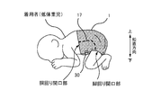
- FIG. 3 is a diagram illustrating a state when the diaper 1 is worn by a low-weight child.
- the diaper 1 of the present embodiment is mainly intended for a low-weight child.
- the wearer is a low weight baby, especially when the wearer is for very low birth weight infants (weight less than 1500 g) or very low birth weight infants (weight less than 1000 g), avoid touching the body as much as possible. Therefore, “minimum handling” is sometimes required to prevent stress. Therefore, after the diaper 1 is worn by a low-weight child, the wearer can keep the posture in which the back is curved in a C shape and the leg is strongly bent in an M shape as shown in FIG. It is desirable to keep the computer in a resting state.
- the posture shown in FIG. 3 is close to the posture of the fetus in the mother's body (fetal-like bending posture) and is easy to rest, and is also called a “positioning posture”.
- the fastening tape 30 that has been engaged with the target tape 29 is peeled off, and the diaper 1 is unfolded in the reverse order of wearing.
- the wearer is in a positioning posture as shown in FIG. 3, the fastening tape 30 is hidden on the stomach side of the wearer. Therefore, in order to peel the fastening tape 30, the wearer's body must be in a supine position so that the abdomen of the wearer can be seen, but the wearer's body must be moved only to remove the diaper 1. Is not preferable from the viewpoint of “minimum handling”. Therefore, in the diaper 1, a cut line 17 is provided on the side flap 14 so that the diaper 1 can be removed without moving the wearer's body.
- FIG. 4 is a diagram illustrating a state when the diaper 1 is removed from the wearer's body.
- the side flap 14 is torn along the cut line 17 from the waistline opening to the leghole opening.
- the diaper 1 can be removed from the wearer's body while the fastening tape 30 is engaged with the abdominal target tape 29. That is, as shown in FIG. 4, by disconnecting the portion where the fastening tape 30 is connected from the side flaps 14 at both lateral ends of the diaper 1, the diaper 1 is in an unfolded state, so that the wearer (low-weight infant The diaper 1 can be easily undressed without changing the posture of).
- 5A and 5B are diagrams illustrating the structure of the cut line 17 of the diaper 1.
- the cut line 17 of the present embodiment is provided on the side flap 14 in the longitudinal rear 7 side, that is, on the side to which the fastening tape 30 is connected, and a plurality of holes 17h extend from the waistline opening to the leghole opening. It is a site formed in a perforated shape by being arranged on the route.
- Each of the plurality of holes 17h penetrates the skin-side sheet 26, the back sheet 24, and the leak-proof sheet 23 in the thickness direction that constitute the side flap 14 in the thickness direction.
- 5A shows an example in which the hole 17h is circular
- FIG. 5B shows an example in which the hole 17h is elliptical.
- the shape of the hole 17h may be other than this, for example, a rectangular slit or the like.
- the size of the hole 17h (the diameter of the opening) is determined according to the size of the diaper 1 and the material of the base material constituting the diaper such as the skin side sheet 26.
- the region of the rear portion 7 in the longitudinal direction of the diaper 1 is divided into three regions: a rear portion 7a, a rear portion 7b, and a rear portion 7c.
- the rear part 7b is an area provided at a position substantially corresponding to the position where the fastening tape 30 is arranged in the vertical direction
- the rear part 7a is an area on the rear side in the vertical direction (outside in the vertical direction) with respect to the rear part 7b.
- the rear portion 7c is a region on the front side in the vertical direction (inner side in the vertical direction) from the rear portion 7b.
- the plurality of holes 17h of the cut line 17 are linear portions arranged in a straight line in the vertical direction along the joint portion 26A between the central strip region 12 and the side flap 14 in the region of the rear portion 7a and the rear portion 7b. Form. Further, the plurality of holes 17h form a curved portion arranged in a region of the rear portion 7c so as to be curved toward the leg-hole opening side of the lateral outer end portion of the diaper 1.
- the cut line 17 has a linear part and a curved part, the side flap 14 can be easily cut even in the state where the diaper 1 is worn. For example, when the wearer of the diaper 1 takes a positioning posture as shown in FIG.
- the leg of the wearer is bent in an M shape and is located on the front side of the body. The part is also located on the front side.
- the side flap 14 is to be broken from the waistline opening to the leg opening, it is necessary to cut it obliquely along the direction in which the leg is bent.
- the tear line 17 is curved toward the leg opening portion, so that the wearer takes a positioning posture by breaking the side flap 14 along the tear line 17. Even when it is removed, the portion of the fastening tape 30 can be easily cut off.
- the interval (pitch) between the holes 17h adjacent to each other on the cut line 17 is different for each region.
- the distance Lhb from the outer peripheral edge of a certain hole 17h in the region of the rear part 7b to the outer peripheral edge of the adjacent hole 17h is adjacent to the outer peripheral edge of the certain hole 17h in the region of the rear part 7a and the rear part 7c. It is wider than the distance Lha to the outer peripheral edge of the hole 17h (Lhb> Lha).
- the ratio of the holes 17h per unit length on the cut line 17 in the region of the rear portion 7b is larger than the ratio of the holes 17h per unit length on the cut line 17 in the region of the rear portion 7a and the rear portion 7c. small.
- the cut line 17 is disposed on the wearer's flank when the diaper 1 is worn.
- the plurality of holes 17h constituting the cut line 17 are often very small, and the cut line 17 is difficult to visually recognize in appearance.
- the diaper 1 of this embodiment is supposed to be worn by a low-weight child, the size of the diaper itself is small, and accordingly, the individual holes 17h are likely to be formed to be small. Therefore, it may be difficult to recognize the position of the cut line 17 when the diaper 1 is undressed.
- low-weight infants are often protected by placing them in an incubator, but the incubator may not be provided with lighting to reproduce the inside of the mother's womb. If it is attempted to attach and detach the diaper 1 in such a dim environment without illumination, it becomes more difficult to recognize the position of the cut line 17.
- the position of the cut line 17 can be easily recognized at the time of attaching / detaching the diaper 1 by making the hole 17h of the cut line 17 conspicuous (easy to see). is doing.
- FIG. 6 is an enlarged view of the area of the rear portion 7b of FIG. 5A.
- FIG. 7 is a diagram illustrating the BB cross section of FIG. In FIG. 6, ten holes 17 h of the holes 17 h 1 to 17 h 10 are shown along the cut line 17. Each hole 17h is represented as a circle having a diameter D1, but the shape of the hole may be other than a circle.
- the hole edge part 17he is in the area
- the hole edge 17he is provided corresponding to each of the plurality of holes 17h constituting the cut line 17, and the distance w from the outer periphery of the hole 17h to the outer periphery of the hole edge 17he is, for example, 0.1 to 1.. It has a size of about 0 mm.
- the leak-proof sheet 23 is a first sheet member
- the skin-side sheet 26 is a second sheet member
- the back sheet 24 is a third sheet member.
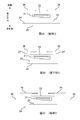
- a joining target region H for joining both sheets is provided. 6 and 7 is a bonding target region H, and in this embodiment, a band-shaped bonding target region H is provided along the vertical direction so as to include the cut line 17. That is, the joining target region H is provided so as to surround the hole 17h. Then, by applying an adhesive such as a hot melt adhesive (HMA) to a predetermined range in the joining target region H between the two sheet members stacked in the thickness direction, the two sheet members A joint 50 is formed to join the two together. Similarly, a joining target region H for joining both sheets is provided between the first sheet member and the third sheet member, and a joining portion 50 is formed in the joining target region H.
- HMA hot melt adhesive
- HMA is applied to the entire range of the joining target region H with respect to at least one of the first sheet member and the second sheet member. That is, the joint portion 50 is formed in a substantially rectangular strip shape along the vertical direction within a range equivalent to the joining target region H. Thereby, each of the plurality of holes 17h constituting the cut line 17 is surrounded by the HMA.
- a coating pattern is referred to as a “coater pattern”.
- the coater pattern two sheet members can be firmly bonded to each other, which is suitable when it is desired to ensure the bonding strength.
- the shape of the bonding portion 50 is not limited to the coater pattern, and the bonding portion 50 can be formed in various patterns other than the coater pattern by changing the HMA coating pattern within the bonding target region H. It is.
- FIG. 8A to 8B are diagrams illustrating examples of other patterns of the joint portion 50.
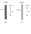
- FIG. FIG. 8A shows an example in which HMA is spirally applied within the region H to be joined. In this specification, such a coating pattern is referred to as a “spiral pattern”.
- a spiral pattern In the joint portion 50 formed by the spiral pattern, it is possible to reduce the amount of HMA used compared to the coater pattern.
- the sheet is suppressed from being hardened by the HMA, and the touch of the diaper 1 in the joining target area H can be kept soft.
- FIG. 8B shows an example in which the HMA is applied so as to meander in the longitudinal direction within the range of the bonding target region H.
- such a coating pattern is referred to as an “omega pattern”.
- the amount of HMA to be used can be reduced as in the spiral pattern, and the touch of the joining target region H can be softened.
- the joint portion 50 and the hole edge portion 17he are formed at positions that overlap in the lateral direction.
- FIG. 9 is a diagram for explaining the state of the hole 17h when a lateral force is applied in FIG.
- a force pulling the side flaps 14 in the lateral direction is applied, as shown in FIG. 9, the first to third sheet members are displaced in the shearing direction.
- a force acts in the direction of expanding the diameter of the opening with respect to the hole 17h formed in each sheet member, and the diameter of the hole 17h represented by D1 in FIG. 7 expands to D2 in FIG. 9 (D2> D1). ).
- FIG. 10 shows a case where a uniform force is applied in the lateral direction to the first to third sheet members.
- two or more adjacent holes 17h of the plurality of holes 17h arranged along the cut line 17 are visible. That is, when the two holes 17h adjacent to each other are the first hole and the second hole, respectively, the first hole edge along the outer periphery of the first hole and the first hole along the outer periphery of the second hole. It is desirable that the two hole edge portions overlap with the joint portion 50 that joins the two sheet members. For example, in FIG. 6, assuming that the hole 17h1 is the first hole and the hole 17h2 adjacent to the hole 17h1 is the second hole, the first hole and the first hole are larger than the first hole alone. This is because it is more conspicuous that the two holes are continuously expanded.
- the joining target region H is set along the cut line 17 and the coater pattern joining portion 50 is formed, all the holes 17h included in the joining target region H appear to expand.
- the entire cut line 17 is easily noticeable.
- ten holes 17h 17h1 to 17h10 arranged in succession are easily visible, and the cut line 17 is easily noticeable.
- a leak-proof sheet 23 made of a film sheet is disposed between the skin side sheet 26 and the back sheet 24.
- the hole 17h in the film sheet the outer shape of the hole 17h can be easily recognized. This is because the film sheet has a smooth surface, and when the holes 17h are formed on the smooth surface, the outer edges (edges) of the holes 17h are easily noticeable. Therefore, the cut line 17 can be made more conspicuous by forming the hole 17h in the side flap 14 at the position where the leakproof sheet 23 is disposed.
- FIG. 10 is a diagram for explaining an example in the case where the bonding portion 50 is formed by an omega pattern (or may be a spiral pattern) in the bonding target region H.
- the joint portion 50 and the hole edge portion 17he overlap each other with respect to the adjacent hole 17h1 and hole 17h2, and the hole 17h4 and hole 17h5. Yes.
- the joining portion 50 that joins the overlapped sheet members and the hole edge portion 17he of two or more adjacent holes 17h among the plurality of holes 17h are overlapped.
- the first hole edge along the outer periphery of the first hole and the second hole edge along the outer periphery of the second hole adjacent to the first hole are connected to the first sheet member and the first hole. It overlaps with the joint part 50 which joins the 2 sheet members. Thereby, the hole 17h penetrating the sheet member is easily visible, and the cut line 17 is easily noticeable.
- FIGS. 11A and 11B are diagrams illustrating an example in which the hole edge portion 17he and the joint portion 50 do not overlap between the first sheet member and the third sheet member.
- FIG. 11A while the hole edge part 17he and the junction part 50 overlap between the 1st sheet
- FIG. 11B shows a case where a lateral force is applied to the sheet member in the state of FIG. 11A. Between the first sheet member and the second sheet member, as described with reference to FIG.
- the diaper 1 in which the cut line 17 is not easily seen from the outside (non-skin side) and the cut line 17 is easily seen from the inside (skin side).
- the cut line 17 is not easily seen from the outside (non-skin side) and the cut line 17 is easily seen from the inside (skin side).
- the hole 17h of the cut line 17 is not conspicuous from the outside of the diaper 1, excrement may leak to the outside of the diaper 1 from the portion of the hole 17h, or when worn. It is possible to suppress anxiety that the diaper 17 may be torn.
- the hole edge 17he and the joint 50 are overlapped, and the first sheet member (leak-proof) between the sheet 23) and the second sheet member (skin-side sheet 26), the hole edge portion 17he and the joint portion 50 may be configured not to overlap each other.
- a part of the cut line 17 is two sheets of a skin side sheet 26 (referred to as a first sheet member) and a back sheet 24 (referred to as a second sheet member).
- the sheet member passes through the overlapped portion. That is, the hole 17h is formed in a portion where the leak-proof sheet 23 does not exist. Also in this case, the adjacent first hole edge 17he and second hole edge 17he, the first sheet member and the second hole edge 17he respectively formed along the outer periphery of the plurality of holes 17h.
- the cut line 17 is formed on the rear portion 7 side of the diaper 1, but the cut line may be formed in another part.
- a cutting line 19, which is a kind of cutting line is formed along the vertical direction from the vertical end portion on the front portion 3 side of the side flap 14.
- the cutting line 19 is constituted by a plurality of holes 19h penetrating a sheet member such as the skin side sheet 26 like the cut line 17, and a hole edge 19he (not shown in FIG. 1) is provided on the outer periphery of the hole 19h. Is formed.
- the joining line 50 that joins two overlapping sheet members and the two or more adjacent hole edge parts 19he overlap so that the cutting line 19 becomes conspicuous as in the case of the cut line 17.
- the cutting line 19 on the front part 3 of the diaper 1, that is, on the abdominal waistline part (first waistline part 3) side, when the diaper 1 is worn, the belly of the diaper 1 along the cutting line 19. It becomes easier to break the side. And the wearer's abdomen can be exposed with the diaper 1 worn while turning over the broken part and turning it back.
- the wearer of the diaper 1 is a low-weight child, it is desirable to irradiate light over a wide range of the body when performing light therapy or the like. In such a case, it is possible to irradiate light over a wide range of the abdomen while minimizing contact with the body of the low-weight infant by breaking and folding the abdomen side of the diaper 1 along the cutting line 19. It becomes.
- the first waistline portion 3 of the diaper 1 is easily bent along the roundness of the wearer's abdomen with the cutting line 19 as a base point. A feeling of fit can be improved.
- the cut line 17 and the cut line 19 are formed at substantially the same position in the lateral direction of the unfolded diaper 1 (see FIG. 1).
- seat member of the state of FIG. 1 is conveyed in the state which continued in multiple numbers in the longitudinal direction. That is, it is conveyed in the direction along the vertical direction in a state where the longitudinal front end of the diaper 1 in the unfolded state and the longitudinal rear end of the diaper 1 different from that are connected.
- the cutting line 19 and the cut line 17 are formed continuously by making a plurality of holes along the vertical direction so as to straddle the connected portions. That is, since the cutting line 19 can be formed at the same time in the process of forming the cut line 17, there is no problem such as an increase in manufacturing cost of the diaper 1.
- the diaper 1 may have the following aspects.
- (Aspect 1) At each position on both sides in the lateral direction, leg-hole elastic members for contracting the leg opening portions in the vertical direction are provided along the vertical direction. Virtually divided into the waist opening portion and the leg opening portion, and when the leg elastic member is viewed from the thickness direction, the leg elasticity A disposable diaper characterized in that the member intersects with the portion on the waistline opening side of the curved portion.
- (Aspect 2) A plurality of sheet members laminated in the thickness direction, and the number of the sheet members stacked in the straight line portion of the cut line is larger than that of the sheet member in at least a part of the curved line portion of the cut line; Disposable diapers characterized by having fewer layers.
- a disposable diaper characterized by having a resin film (leak-proof sheet) in which the stretching direction at the time of manufacture is along the vertical direction, and the linear portion of the cut line 17 is formed on the resin film.
- Aspect 4 At each position on both sides in the lateral direction, sheet-like three-dimensional gathers (leg side gathers) forming portions provided along the vertical direction are provided, and the three-dimensional gather forming portions stand up in the thickness direction.
- the longitudinal contraction force acting on the standing portion which has a base end portion that is impossible and a standing portion that can stand on the skin side in the thickness direction with the base end portion serving as a fulcrum, arranged side by side in the lateral direction.
- the upright portion is contracted in the vertical direction based on the vertical direction, so that the upright portion rises on the skin side in the thickness direction, and the cut line is closer to the lateral direction than the proximal end portion and the upright portion.
- a disposable diaper characterized by being formed at an outer position. (Aspect 5)
- An absorbent core (absorber) formed by laminating a liquid absorbent material that absorbs liquid in the thickness direction is provided at the center in the lateral direction, and the cut line is in the lateral direction rather than the absorbent core.
- the disposable diaper characterized by being formed in the outer position of.
- 1 disposable diapers (diapers), 3 front (first waistline), 5 crotch, 7 rear (second waistline), 12 Central strip area, 14 side flaps, 15 Leg gathers, 16 Legside gather, 17 Cut line, 17h hole, 17h1-17h5 hole, 17he hole edge, 19 cutting line, 19h hole, 19he hole edge, 21 Absorber, 22 Top sheet, 23 Leak-proof sheet, 24 Back sheet (exterior sheet), 26 Skin side sheet, 27 elastic member, 29 Target tape, 30 Fastening tape, 50 joints, H bonding target area, HMA hot melt adhesive
Landscapes
- Health & Medical Sciences (AREA)
- Epidemiology (AREA)
- Engineering & Computer Science (AREA)
- Biomedical Technology (AREA)
- Heart & Thoracic Surgery (AREA)
- Vascular Medicine (AREA)
- Life Sciences & Earth Sciences (AREA)
- Animal Behavior & Ethology (AREA)
- General Health & Medical Sciences (AREA)
- Public Health (AREA)
- Veterinary Medicine (AREA)
- Absorbent Articles And Supports Therefor (AREA)
Abstract
Description
第1胴回り部と股下部と第2胴回り部とを縦方向に並んで有し、第1のシート部材と第2のシート部材とが重ね合わされたサイドフラップと、前記サイドフラップの前記第2胴回り部側に接合されたファスニングテープと、前記サイドフラップの前記第2胴回り部側に設けられ、前記第1のシート部材及び前記第2のシート部材を貫通する複数の孔が並ぶ切り取り線と、を備える使い捨ておむつであって、前記第1のシート部材は、第1の孔の外周に沿った第1の孔縁部と、前記第1の孔と隣り合う第2の孔の外周に沿った第2の孔縁部を有し、重ね合わされた前記第1のシート部材と前記第2のシート部材とを接合する接合部と、前記第1の孔縁部及び前記第2の孔縁部とが重複する、ことを特徴とする使い捨ておむつである。
本発明の他の特徴については、本明細書及び添付図面の記載により明らかにする。
第1胴回り部と股下部と第2胴回り部とを縦方向に並んで有し、第1のシート部材と第2のシート部材とが重ね合わされたサイドフラップと、前記サイドフラップの前記第2胴回り部側に接合されたファスニングテープと、前記サイドフラップの前記第2胴回り部側に設けられ、前記第1のシート部材及び前記第2のシート部材を貫通する複数の孔が並ぶ切り取り線と、を備える使い捨ておむつであって、前記第1のシート部材は、第1の孔の外周に沿った第1の孔縁部と、前記第1の孔と隣り合う第2の孔の外周に沿った第2の孔縁部を有し、重ね合わされた前記第1のシート部材と前記第2のシート部材とを接合する接合部と、前記第1の孔縁部及び前記第2の孔縁部とが重複する、ことを特徴とする使い捨ておむつ。
前記第1の孔縁部及び前記第2の孔縁部は、前記第1のシート部材と前記第2のシート部材とを接合する接合部と重複し、前記第1のシート部材と前記第3のシート部材とを接合する接合部と重複しない、ことが望ましい。
<使い捨ておむつ1の基本構成>
本実施形態の使い捨ておむつ1(以下、単におむつ1とも呼ぶ)は、主に新生児や乳幼児を着用対象とした使い捨ておむつであり、体重が3000g以下の低体重児、特に体重が2500g未満の低出生体重児に好適に用いられる。なお、低体重児には、低出生体重児(体重2500g未満)だけでなく、極低出生体重児用(体重1500g未満)や超低出生体重児用(体重1000g未満)も含まれる。
次に、おむつ1の着脱方法について説明する。まず、おむつ1を着用者に着用させる際には、図1のように展開させた状態のおむつ1を、中央帯状領域12の後部7が着用者の背側に、後部3が着用者の腹側に沿うように配置する。そして、サイドフラップ14の後部7を着用者の背側から腹側に胴回り方向に巻き付けるようにして前部3に設けられたターゲットテープ29にファスニングテープ30を係合させる。
おむつ1に設けられた切り取り線17の詳細な構造について説明する。
切り取り線17はおむつ1の着用時において、着用者の脇腹部に配置されている。しかし、切り取り線17を構成する複数の孔17hは非常に小さい場合が多く、切り取り線17は外観上視認しにくい。実際に、本実施形態のおむつ1は低体重児に着用させることを想定しているためおむつ自体のサイズが小さく、それに伴って個々の孔17hも小さめに形成される可能性が高い。そのため、おむつ1を脱衣させる際に切り取り線17の位置を認識することが難しくなる場合がある。また、病院等では低体重児を保育器に入れて保護していることが多いが、保育器は母体の子宮内を再現するために照明が設けられていない場合がある。そのような照明の無い薄暗い環境でおむつ1の着脱作業を行おうとすると、切り取り線17の位置を認識することがより困難になる。
上述の実施形態では、第1~第3のシート部材のそれぞれについて、孔縁部17heと接合部50とが重複している例について説明したが、3枚のシート部材のうち重なり合う2枚のシート部材間において孔縁部17heと接合部50とが重複していれば、当該部分において切り取り線17を目立ちやすくすることができる。
上記の実施形態は、本発明の理解を容易にするためのものであり、本発明を限定して解釈するためのものではない。本発明は、その趣旨を逸脱することなく、変更・改良され得ると共に、本発明には、その等価物が含まれることは言うまでもない。
おむつ1の前部3、すなわち腹側の胴回り部(第1胴回り部3)側に切断線19が形成されることにより、おむつ1の着用時において、当該切断線19に沿っておむつ1の腹側を破りやすくなる。そして、破られた部分をめくって折り返すことで、おむつ1を着用した状態のまま、着用者の腹部を露出させることができる。おむつ1の着用者が低体重児である場合、光線治療等を実施する際に身体の広い範囲に光線を照射することが望ましい。このような場合、切断線19に沿っておむつ1の腹部側を破って折り返すことで、低体重児の身体への接触を最小限に抑えつつ、腹部の広い範囲に光線を照射させることが可能となる。また、図1に示される位置に切断線19が設けられることにより、当該切断線19を基点としておむつ1の第1胴回り部3が着用者の腹部の丸みに沿って折れ曲がりやすくなり、おむつ1のフィット感を向上させることができる。
なお、切り取り線17と切断線19は展開状態のおむつ1の横方向においてほぼ同一の位置に形成されている(図1参照)。おむつ1を製造する際には、図1の状態のシート部材が縦方向に連続して複数連なった状態で搬送される。すなわち、展開状態のおむつ1の縦方向前側端部と、それとは異なるおむつ1の縦方向後側端部とが接続された状態で縦方向に沿った方向に搬送される。そして、搬送過程において、当該接続された部分を跨ぐように縦方向に沿って複数の孔を空けることで、切断線19と切り取り線17とが連続して形成される。つまり、切り取り線17を形成する工程で切断線19も同時に形成することが可能であるため、おむつ1の製造コストが上昇する等の問題は生じない。
(態様1)
横方向の両側の各位置には、それぞれ、脚回り開口部となる部分を縦方向に収縮させるための脚回り弾性部材が前記縦方向に沿って設けられており、切り取り線の曲線状部分を仮想的に前記胴回り開口部側の部分と前記脚回り開口部側の部分とに二分した場合であって、しかも、前記厚さ方向から前記脚回り弾性部材を見た場合に、前記脚回り弾性部材は、前記曲線状部分のうちの前記胴回り開口部側の部分と交差していることを特徴とする使い捨ておむつ。
(態様2)
厚さ方向に積層された複数のシート部材を有し、切り取り線の直線状部分での前記シート部材の積層枚数よりも、切り取り線の曲線状部分のうちの少なくとも一部での前記シート部材の積層枚数の方が少ないことを特徴とする使い捨ておむつ。
(態様3)
製造時の延伸方向が縦方向に沿った樹脂フィルム(防漏シート)を有し、切り取り線17の直線状部分は、前記樹脂フィルムに形成されていることを特徴とする使い捨ておむつ。
(態様4)
横方向の両側の各位置には、それぞれ縦方向に沿って設けられたシート状の立体ギャザー(レッグサイドギャザー)形成部が設けられており、前記立体ギャザー形成部は、前記厚さ方向に起立不能な基端部と、前記基端部を支点として前記厚さ方向の肌側に起立可能な起立部とを前記横方向に並んで有し、前記起立部に作用する前記縦方向の収縮力に基づいて前記起立部が前記縦方向に収縮することによって、前記起立部が前記厚さ方向の肌側に起立し、前記切り取り線は、前記基端部及び前記起立部よりも前記横方向の外側の位置に形成されていることを特徴とする使い捨ておむつ。
(態様5)
液体を吸収する液体吸収性素材を前記厚さ方向に積層してなる吸収性コア(吸収体)を、前記横方向の中央に有し、前記切り取り線は、前記吸収性コアよりも前記横方向の外側の位置に形成されていることを特徴とする使い捨ておむつ。
3 前部(第1胴回り部)、5 股下部、7 後部(第2胴回り部)、
12 中央帯状領域、
14 サイドフラップ、
15 レッグギャザー、
16 レッグサイドギャザー、
17 切り取り線、17h 孔、17h1~17h5 孔、17he 孔縁部、
19 切断線、19h 孔、19he 孔縁部、
21 吸収体、
22 トップシート、
23 防漏シート、
24 バックシート(外装シート)、
26 肌側シート、
27 弾性部材、
29 ターゲットテープ、
30 ファスニングテープ、
50 接合部、
H 接合対象領域、
HMA ホットメルト接着剤
Claims (10)
- 第1胴回り部と股下部と第2胴回り部とを縦方向に並んで有し、
第1のシート部材と第2のシート部材とが重ね合わされたサイドフラップと、
前記サイドフラップの前記第2胴回り部側に接合されたファスニングテープと、
前記サイドフラップの前記第2胴回り部側に設けられ、前記第1のシート部材及び前記第2のシート部材を貫通する複数の孔が並ぶ切り取り線と、
を備える使い捨ておむつであって、
前記第1のシート部材は、第1の孔の外周に沿った第1の孔縁部と、前記第1の孔と隣り合う第2の孔の外周に沿った第2の孔縁部を有し、
重ね合わされた前記第1のシート部材と前記第2のシート部材とを接合する接合部と、前記第1の孔縁部及び前記第2の孔縁部とが重複する、
ことを特徴とする使い捨ておむつ。 - 請求項1に記載の使い捨ておむつであって、
前記第1のシート部材は、複数の前記孔のそれぞれについて、前記孔の外周に沿った孔縁部を有し、
複数の前記孔縁部のうち全ての孔縁部が、前記第1のシート部材と前記第2のシート部材とを接合する接合部と重複する、ことを特徴とする使い捨ておむつ。 - 請求項1または2に記載の使い捨ておむつであって、
前記第2のシート部材とは反対側の面で前記第1のシート部材と重ね合わされる第3のシート部材を有し、
前記第1の孔縁部及び前記第2の孔縁部は、前記第1のシート部材と前記第2のシート部材とを接合する接合部及び前記第1のシート部材と前記第3のシート部材とを接合する接合部と重複する、ことを特徴とする使い捨ておむつ。 - 請求項1または2に記載の使い捨ておむつであって、
前記第2のシート部材とは反対側の面で前記第1のシート部材と重ね合わされる第3のシート部材を有し、
前記第1の孔縁部及び前記第2の孔縁部は、前記第1のシート部材と前記第2のシート部材とを接合する接合部と重複し、前記第1のシート部材と前記第3のシート部材とを接合する接合部と重複しない、ことを特徴とする使い捨ておむつ。 - 請求項1~4のいずれかに記載の使い捨ておむつであって、
前記第1のシート部材は、フィルムシートによって形成されている、ことを特徴とする使い捨ておむつ。 - 請求項1~5のいずれかに記載の使い捨ておむつであって、
前記接合部は、前記第1のシート部材及び前記第2のシート部材のうち少なくとも一方にホットメルト接着剤を螺旋状に塗布することによって形成されている、ことを特徴とする使い捨ておむつ。 - 請求項1~6のいずれかに記載の使い捨ておむつであって、
前記縦方向において前記ファスニングテープが配置されている領域と対応する領域中で前記切り取り線が伸びる方向の単位長さ当たりに占める前記孔の割合は、
前記縦方向において前記ファスニングテープが配置されていない領域と対応する領域中で前記切り取り線が伸びる方向の単位長さ当たりに占める前記孔の割合よりも小さい、ことを特徴とする使い捨ておむつ。 - 請求項1~7のいずれかに記載の使い捨ておむつであって、
前記ファスニングテープを、それぞれ、前記第1胴回り部に係合させることによって、一つの胴回り開口部と一対の脚回り開口部とが形成され、
前記切り取り線に含まれる複数の前記孔は、前記胴回り開口部となる部分から、前記脚回り開口部となる部分へ延びたルート上に並んでいる、ことを特徴とする使い捨ておむつ。 - 請求項8に記載の使い捨ておむつであって、
前記切り取り線は、前記胴回り開口部となる部分から前記縦方向に延びる直線状部分と、
前記直線部分よりも前記縦方向の内側の位置で、前記横方向の外側に湾曲した曲線状部分と、
を有する、ことを特徴とする使い捨ておむつ。 - 請求項1~9のいずれかに記載の使い捨ておむつであって、
前記サイドフラップの前記第1胴回り部側に設けられ、前記横方向の位置に関して前記切り取り線と同じ位置に、前記第1のシート部材及び前記第2のシート部材を貫通する複数の孔が並ぶ切断線を備える、ことを特徴とする使い捨ておむつ。
Priority Applications (5)
| Application Number | Priority Date | Filing Date | Title |
|---|---|---|---|
| MYPI2017700167A MY181978A (en) | 2014-07-25 | 2015-07-24 | Disposable diaper |
| AU2015293070A AU2015293070B2 (en) | 2014-07-25 | 2015-07-24 | Disposable diaper |
| KR1020177004933A KR102214369B1 (ko) | 2014-07-25 | 2015-07-24 | 일회용 기저귀 |
| CN201580041294.5A CN106572931B (zh) | 2014-07-25 | 2015-07-24 | 一次性尿布 |
| PH12017500092A PH12017500092B1 (en) | 2014-07-25 | 2017-01-13 | Disposable diaper |
Applications Claiming Priority (2)
| Application Number | Priority Date | Filing Date | Title |
|---|---|---|---|
| JP2014152185A JP6400971B2 (ja) | 2014-07-25 | 2014-07-25 | 使い捨ておむつ |
| JP2014-152185 | 2014-07-25 |
Publications (1)
| Publication Number | Publication Date |
|---|---|
| WO2016013662A1 true WO2016013662A1 (ja) | 2016-01-28 |
Family
ID=55163184
Family Applications (1)
| Application Number | Title | Priority Date | Filing Date |
|---|---|---|---|
| PCT/JP2015/071129 Ceased WO2016013662A1 (ja) | 2014-07-25 | 2015-07-24 | 使い捨ておむつ |
Country Status (7)
| Country | Link |
|---|---|
| JP (1) | JP6400971B2 (ja) |
| KR (1) | KR102214369B1 (ja) |
| CN (1) | CN106572931B (ja) |
| AU (1) | AU2015293070B2 (ja) |
| MY (1) | MY181978A (ja) |
| PH (1) | PH12017500092B1 (ja) |
| WO (1) | WO2016013662A1 (ja) |
Cited By (6)
| Publication number | Priority date | Publication date | Assignee | Title |
|---|---|---|---|---|
| US10675188B2 (en) | 2016-02-25 | 2020-06-09 | The Procter & Gamble Company | Configurable absorbent articles |
| US11399992B2 (en) | 2017-08-24 | 2022-08-02 | The Procter & Gamble Company | Configurable absorbent articles having removable fastening members |
| US11452646B2 (en) | 2017-06-05 | 2022-09-27 | The Procter & Gamble Company | Configurable absorbent articles having improved bodily exudate visualization |
| US11730633B2 (en) | 2019-02-21 | 2023-08-22 | The Procter & Gamble Company | Absorbent articles having fully removable fastening members |
| US12419793B2 (en) | 2021-09-10 | 2025-09-23 | The Procter & Gamble Company | Absorbent article comprising a multi-layer cushion layer |
| US12478514B2 (en) | 2022-06-30 | 2025-11-25 | The Procter & Gamble Company | Absorbent articles with frangible pathways and disposal features |
Citations (6)
| Publication number | Priority date | Publication date | Assignee | Title |
|---|---|---|---|---|
| JPH01141711U (ja) * | 1988-03-14 | 1989-09-28 | ||
| JPH0631725U (ja) * | 1992-10-02 | 1994-04-26 | ユニ・チャーム株式会社 | 使い捨ておむつ |
| JP2003111793A (ja) * | 2001-10-05 | 2003-04-15 | Uni Charm Corp | 開放型の使い捨ておむつ |
| JP2004105698A (ja) * | 2002-07-26 | 2004-04-08 | Kao Corp | 前後どちらからでも装着が容易なおむつ |
| JP2008245960A (ja) * | 2007-03-30 | 2008-10-16 | Livedo Corporation | 吸収性物品の製造方法および吸収性物品 |
| JP2010035726A (ja) * | 2008-08-04 | 2010-02-18 | Oji Nepia Co Ltd | テープ型使い捨ておむつ |
Family Cites Families (10)
| Publication number | Priority date | Publication date | Assignee | Title |
|---|---|---|---|---|
| US20030078558A1 (en) * | 1999-02-10 | 2003-04-24 | Hamzeh Karami | Disposable pant type absorbent article with improved fasteners and method of making same |
| US20030130641A1 (en) * | 2001-12-28 | 2003-07-10 | Richlen Sandra A. | Absorbent garment having a weakened region |
| JP4558080B1 (ja) * | 2009-03-31 | 2010-10-06 | ユニ・チャーム株式会社 | 吸収性物品 |
| JP5200143B2 (ja) * | 2011-08-31 | 2013-05-15 | ユニ・チャーム株式会社 | 使い捨ておむつ |
| TWI569788B (zh) | 2011-11-22 | 2017-02-11 | 優你 嬌美股份有限公司 | 用後即棄式紙尿布 |
| JP5266379B2 (ja) | 2011-12-28 | 2013-08-21 | ユニ・チャーム株式会社 | 使い捨ておむつ |
| JP5291212B2 (ja) | 2012-02-07 | 2013-09-18 | ユニ・チャーム株式会社 | 開放型使い捨ておむつ |
| JP5291216B1 (ja) | 2012-03-30 | 2013-09-18 | ユニ・チャーム株式会社 | 使い捨ておむつ |
| JP5243641B1 (ja) | 2012-04-27 | 2013-07-24 | ユニ・チャーム株式会社 | 使い捨ておむつ |
| JP5690966B1 (ja) * | 2014-07-25 | 2015-03-25 | ユニ・チャーム株式会社 | 展開型使い捨ておむつ |
-
2014
- 2014-07-25 JP JP2014152185A patent/JP6400971B2/ja active Active
-
2015
- 2015-07-24 KR KR1020177004933A patent/KR102214369B1/ko active Active
- 2015-07-24 WO PCT/JP2015/071129 patent/WO2016013662A1/ja not_active Ceased
- 2015-07-24 AU AU2015293070A patent/AU2015293070B2/en not_active Ceased
- 2015-07-24 CN CN201580041294.5A patent/CN106572931B/zh active Active
- 2015-07-24 MY MYPI2017700167A patent/MY181978A/en unknown
-
2017
- 2017-01-13 PH PH12017500092A patent/PH12017500092B1/en unknown
Patent Citations (6)
| Publication number | Priority date | Publication date | Assignee | Title |
|---|---|---|---|---|
| JPH01141711U (ja) * | 1988-03-14 | 1989-09-28 | ||
| JPH0631725U (ja) * | 1992-10-02 | 1994-04-26 | ユニ・チャーム株式会社 | 使い捨ておむつ |
| JP2003111793A (ja) * | 2001-10-05 | 2003-04-15 | Uni Charm Corp | 開放型の使い捨ておむつ |
| JP2004105698A (ja) * | 2002-07-26 | 2004-04-08 | Kao Corp | 前後どちらからでも装着が容易なおむつ |
| JP2008245960A (ja) * | 2007-03-30 | 2008-10-16 | Livedo Corporation | 吸収性物品の製造方法および吸収性物品 |
| JP2010035726A (ja) * | 2008-08-04 | 2010-02-18 | Oji Nepia Co Ltd | テープ型使い捨ておむつ |
Cited By (14)
| Publication number | Priority date | Publication date | Assignee | Title |
|---|---|---|---|---|
| US10675188B2 (en) | 2016-02-25 | 2020-06-09 | The Procter & Gamble Company | Configurable absorbent articles |
| US11344454B2 (en) | 2016-02-25 | 2022-05-31 | The Procter & Gamble Company | Configurable absorbent articles |
| US12263073B2 (en) | 2017-06-05 | 2025-04-01 | The Procter & Gamble Company | Configurable absorbent articles having improved bodily exudate visualization |
| US11452646B2 (en) | 2017-06-05 | 2022-09-27 | The Procter & Gamble Company | Configurable absorbent articles having improved bodily exudate visualization |
| US11399992B2 (en) | 2017-08-24 | 2022-08-02 | The Procter & Gamble Company | Configurable absorbent articles having removable fastening members |
| US11730633B2 (en) | 2019-02-21 | 2023-08-22 | The Procter & Gamble Company | Absorbent articles having fully removable fastening members |
| US12161538B2 (en) | 2019-02-21 | 2024-12-10 | The Procter & Gamble Company | Absorbent articles having fully removable fastening members |
| US12419793B2 (en) | 2021-09-10 | 2025-09-23 | The Procter & Gamble Company | Absorbent article comprising a multi-layer cushion layer |
| US12478514B2 (en) | 2022-06-30 | 2025-11-25 | The Procter & Gamble Company | Absorbent articles with frangible pathways and disposal features |
| US12478513B2 (en) | 2022-06-30 | 2025-11-25 | The Procter & Gamble Company | Absorbent articles and methods and apparatuses for making absorbent articles with frangible pathways |
| US12521285B2 (en) | 2022-06-30 | 2026-01-13 | The Procter & Gamble Company | Absorbent articles with frangible pathways |
| US12582561B2 (en) | 2022-06-30 | 2026-03-24 | The Procter & Gamble Company | Absorbent articles with frangible pathways with simultaneously propagating tear zones |
| US12582562B2 (en) | 2022-06-30 | 2026-03-24 | The Procter & Gamble Company | Absorbent articles with frangible pathways adapted for tear propagation between regions of laminates having different numbers of layers of substrates |
| US12599508B2 (en) | 2022-06-30 | 2026-04-14 | The Procter & Gamble Company | Absorbent articles and methods for making absorbent articles with frangible pathways |
Also Published As
| Publication number | Publication date |
|---|---|
| CN106572931A (zh) | 2017-04-19 |
| PH12017500092B1 (en) | 2020-11-06 |
| PH12017500092A1 (en) | 2017-05-22 |
| CN106572931B (zh) | 2020-10-23 |
| AU2015293070B2 (en) | 2019-02-07 |
| AU2015293070A1 (en) | 2017-02-02 |
| KR102214369B1 (ko) | 2021-02-08 |
| MY181978A (en) | 2021-01-18 |
| JP2016029974A (ja) | 2016-03-07 |
| KR20170036006A (ko) | 2017-03-31 |
| JP6400971B2 (ja) | 2018-10-03 |
Similar Documents
| Publication | Publication Date | Title |
|---|---|---|
| JP6461505B2 (ja) | 使い捨ておむつ | |
| CN111093579B (zh) | 伸缩性片和吸收性物品 | |
| JP5769398B2 (ja) | 使い捨て着用物品 | |
| KR101522830B1 (ko) | 전개형 일회용 기저귀 | |
| JP6400971B2 (ja) | 使い捨ておむつ | |
| KR101806093B1 (ko) | 전개형 일회용 기저귀 | |
| JP6424085B2 (ja) | 展開型使い捨ておむつ | |
| JP6342249B2 (ja) | 使い捨ておむつ | |
| TWI601518B (zh) | Absorbent article | |
| JP2016000116A (ja) | 使い捨て着用物品 | |
| WO2013031645A1 (ja) | 使い捨ておむつ | |
| JP2016104078A (ja) | 展開型着用物品 | |
| JP2016030201A (ja) | 展開型使い捨ておむつ | |
| WO2013089198A1 (ja) | 使い捨て着用物品 | |
| JP2019187718A (ja) | パンツ型使い捨ておむつ | |
| WO2015107765A1 (ja) | 使い捨てのパンツ型着用物品 | |
| JP7321494B2 (ja) | 使い捨て吸収性物品 | |
| JP5906045B2 (ja) | 使い捨て着用物品 | |
| JP7081920B2 (ja) | パンツ型吸収性物品 | |
| JP6469038B2 (ja) | 使い捨ておむつ | |
| JP2016064191A (ja) | 使い捨て着用物品 | |
| JP2013052307A (ja) | 使い捨ておむつ |
Legal Events
| Date | Code | Title | Description |
|---|---|---|---|
| 121 | Ep: the epo has been informed by wipo that ep was designated in this application |
Ref document number: 15825066 Country of ref document: EP Kind code of ref document: A1 |
|
| WWE | Wipo information: entry into national phase |
Ref document number: 12017500092 Country of ref document: PH |
|
| NENP | Non-entry into the national phase |
Ref country code: DE |
|
| ENP | Entry into the national phase |
Ref document number: 2015293070 Country of ref document: AU Date of ref document: 20150724 Kind code of ref document: A |
|
| ENP | Entry into the national phase |
Ref document number: 20177004933 Country of ref document: KR Kind code of ref document: A |
|
| 122 | Ep: pct application non-entry in european phase |
Ref document number: 15825066 Country of ref document: EP Kind code of ref document: A1 |