WO2016013328A1 - 鋼管杭の継手構造 - Google Patents
鋼管杭の継手構造 Download PDFInfo
- Publication number
- WO2016013328A1 WO2016013328A1 PCT/JP2015/067008 JP2015067008W WO2016013328A1 WO 2016013328 A1 WO2016013328 A1 WO 2016013328A1 JP 2015067008 W JP2015067008 W JP 2015067008W WO 2016013328 A1 WO2016013328 A1 WO 2016013328A1
- Authority
- WO
- WIPO (PCT)
- Prior art keywords
- fitting
- steel pipe
- pipe pile
- step portion
- fitting step
- Prior art date
- Legal status (The legal status is an assumption and is not a legal conclusion. Google has not performed a legal analysis and makes no representation as to the accuracy of the status listed.)
- Ceased
Links
Images
















Classifications
-
- E—FIXED CONSTRUCTIONS
- E02—HYDRAULIC ENGINEERING; FOUNDATIONS; SOIL SHIFTING
- E02D—FOUNDATIONS; EXCAVATIONS; EMBANKMENTS; UNDERGROUND OR UNDERWATER STRUCTURES
- E02D5/00—Bulkheads, piles, or other structural elements specially adapted to foundation engineering
- E02D5/22—Piles
- E02D5/24—Prefabricated piles
Definitions
- the present invention relates to a joint structure for steel pipe piles.
- This application claims priority based on Japanese Patent Application No. 2014-150437 for which it applied to Japan on July 24, 2014, and uses the content here.
- Patent Documents 1 and 2 Conventionally, joint structures of steel pipe piles disclosed in Patent Documents 1 and 2 have been proposed for the purpose of connecting a plurality of steel pipe piles in the axial direction with mechanical joints.
- the outer fitting end portion is formed to have a larger diameter at the engagement convex portion forming portion provided on the distal end side than the engaging convex portion forming portion provided on the proximal end side, and the inner fitting end portion. Is formed with a smaller diameter in the portion where the engaged convex portion provided on the distal end side is formed than in the portion where the engaged convex portion provided on the proximal end side is formed.
- the present invention has been made in view of the above circumstances, reduces the labor of rotating the steel pipe pile, avoids an increase in the plate thickness of the steel pipe pile more than necessary, and has an external fitting end portion and an internal fitting end portion. It aims at providing the joint structure of a steel pipe pile which can provide sufficient tensile strength and compression strength.
- a first aspect of the present invention is a steel pipe pile joint structure in which a first steel pipe pile and a second steel pipe pile are joined in series.
- the joint structure of the steel pipe pile is provided at one end of the first steel pipe pile, and an external fitting end part in which a plurality of external fitting step parts are formed along the axial direction of the first steel pipe pile;
- An inner fitting end portion provided at one end of the steel pipe pile and inserted into the outer fitting end portion, and a plurality of inner fitting step portions are formed along the axial direction of the second steel pipe pile;
- Each of the plurality of external fitting step portions protrudes from the inner peripheral surface thereof toward the radially inner side of the first steel pipe pile and is provided along the circumferential direction of the first steel pipe pile.
- a plurality of external fitting groove portions formed between the external fitting mountain portions, the external fitting mountain portions adjacent to each other in the circumferential direction of the first steel pipe pile, and adjacent to the respective external fitting mountain portions on the inner peripheral surface.
- an outer fitting valley portion formed on a proximal end side close to the first steel pipe pile, and each of the plurality of inner fitting step portions has an outer peripheral surface thereof. Projecting outward in the radial direction of the second steel pipe pile and adjacent to each other in the circumferential direction of the second steel pipe pile, and a plurality of internally fitted mountain portions provided along the circumferential direction of the second steel pipe pile.
- the plurality of external fitting stepped portions, the outer fitting stepped portion closer to the first steel pipe pile is formed so that the plate thickness of the external fitting valley portion is increased, and the plurality of internal fitting stepped portions Part, the plate thickness of the internal fitting valley portion is formed so that the internal fitting step portion closer to the second steel pipe pile, the number of the plurality of external fitting mountain portions in each of the external fitting step portions, and the respective
- the number of the plurality of internal fitting mountain portions in the internal fitting step portion is 8 or more, respectively, and is the outer fitting step portion furthest from the first steel pipe pile.
- the length of the outer fitting mountain portion in the axial direction of the first steel pipe pile and the outer The sum of the length of the fitting valley portion and the sum of the length of the inner fitting mountain portion and the length of the inner fitting valley portion in the axial center direction of the second steel pipe pile are respectively defined as Lg1, and the first steel pipe pile
- the length of the outer fitting mountain portion in the axial direction of the second steel pipe pile and the length of the inner fitting mountain portion in the axial direction of the second steel pipe pile are respectively defined as Lm1
- the width in the circumferential direction is defined as C2, and the second outer fitting step portion adjacent to the first outer fitting step portion, and the second inner fitting step portion adjacent to the first inner fitting step portion,
- the compression area of the compression side abutment surface that bears the force and the compression area of the compression side abutment surface that bears the compression force in the first internal fitting step portion are defined as Ac1, respectively, and in the second external fitting step portion
- the compression area of the compression side abutment surface that bears the compression force and the compression area of the compression side abutment surface that bears the compression force at the second internal fitting step are defined as Ac2, respectively, and the second external fitting
- the sum of the length of the external fitting mountain portion and the length of the external fitting valley portion in the axial direction of the first steel pipe pile, and the axial center of the second steel pipe pile Lg is the sum of the length of the inner fitting mountain portion and the length of the inner fitting valley portion in each direction.
- the configuration may be as follows: the number of the plurality of external fitting step portions is 4, and the first external fitting step portion The plate thickness of the external fitting valley portion is 50% or more and 80% or less of the plate thickness of the external fitting valley portion of the external fitting step portion closest to the first steel pipe pile.
- the configuration may be as follows: the number of the plurality of external fitting step portions is 3, and the first external fitting step portion The plate thickness of the external fitting valley portion is 60% or more and 80% or less of the plate thickness of the external fitting valley portion of the external fitting step portion closest to the first steel pipe pile.
- the configuration may be as follows: the number of the plurality of external fitting step portions is 2, and the first outer fitting step portion The plate thickness of the external fitting valley portion is 70% or more and 90% or less of the plate thickness of the external fitting valley portion of the second external fitting step portion.
- the configuration may be as follows: the number of the plurality of external fitting step portions is 5 or more and 9 or less, and the first external fitting step.
- board thickness of the said external fitting trough part of a part is 35% or more and 70% or less of the board thickness of the said external fitting trough part of the external fitting step part nearest to the said 1st steel pipe pile.
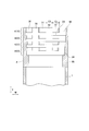
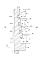
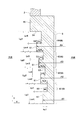
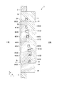
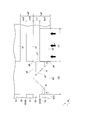
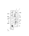
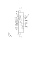
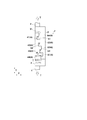
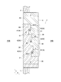
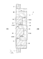
- FIG. It is a fragmentary sectional view which shows the external fitting end part of the said joint structure. It is a fragmentary sectional view which shows the internal fitting end part of the said joint structure. It is a fragmentary sectional view showing the above-mentioned joint structure. It is a fragmentary sectional view which shows the said joint structure, Comprising: It is a figure which shows the tensile force and bending force which act on the 1st external fitting step part of an external fitting end part.
- a steel pipe pile joint structure 7 according to an embodiment of the present invention (hereinafter, sometimes referred to as a joint structure 7 according to the present embodiment or simply a joint structure 7) will be described in detail with reference to the drawings. .
- the duplicate description is abbreviate
- the axial direction of the steel pipe pile is defined as the axial direction Y
- the direction orthogonal to the axial direction Y is the axial orthogonal direction X
- the direction around the axial center of the steel pipe pile is the circumferential direction W.
- FIG. 1 is a perspective view showing a steel pipe pile joint structure 7 according to this embodiment.
- the joint structure 7 is configured such that the first steel pipe pile 1 and the second steel pipe pile 2 having a circular cross section are connected to each other along the axial direction Y in a foundation pile or the like of a structure constructed on the ground. Used as a mechanical joint to be connected.
- the joint structure 7 includes a hollow cylindrical outer fitting end 3 provided at the upper end of the first steel pipe pile 1 and a hollow cylindrical inner fitting end 5 provided at the lower end of the second steel pipe pile 2. .
- the outer fitting end portion 3 and the inner fitting end portion 5 have a structure that can be fitted to each other.
- the outer fitting end 3 is joined to the upper end of the first steel pipe pile 1 by welding or the like, and the inner fitting end 5 is joined to the lower end of the second steel pipe pile 2 by welding or the like.
- the outer fitting end portion 3 includes the first outer fitting step portion 41, the second outer fitting step portion 42, the third outer fitting step portion 43, and the first outer fitting step portion 43 in order from the distal end side to the proximal end side in the axial direction Y. 4 It has the external fitting step part 44.
- the inner fitting end portion 5 includes, in order from the distal end side to the proximal end side in the axial direction Y, the first inner fitting step portion 61, the second inner fitting step portion 62, the third inner fitting step portion 63, and A fourth internal stepped portion 64 is provided.
- the lower side in the axial direction Y (side closer to the first steel pipe pile 1) is the proximal end side in the external fitting end portion 3, and the upper side in the axial direction Y (close to the second steel pipe pile 2).
- Side is a base end side in the inner fitting end portion 5.
- the side opposite to the base end side of the outer fitting end portion 3 and the inner fitting end portion 5 is referred to as a distal end side.
- Each of the four outer fitting stepped portions 4 has an inner wall surface (inner circumferential surface) of the outer fitting end portion 3 and a direction orthogonal to the axial center direction X of the first steel pipe pile 1 (direction perpendicular to the axial direction Y (radial direction) ): Refer to FIG. 1) of the eight external fitting mountain portions 31 protruding along the circumferential direction W while projecting to the center side (radially inner side) and the external fitting mountain portions 31 adjacent to each other in the circumferential direction W. 8 external fitting groove portions 32 formed therebetween, and an external fitting valley portion 33 formed adjacent to the external fitting mountain portion 31 in the axial direction Y and close to the first steel pipe pile 1.
- the external fitting groove part 32 and the external fitting trough part 33 are formed with the same board thickness so that it may become mutually flush, fitting property and It is preferable from the viewpoint of workability.
- FIG. 2 is a view showing the external fitting end portion 3 and is a cross-sectional view when seen in a cross section including the axis of the first steel pipe pile 1.
- the plate thickness of the outer fitting groove portion 32 is made smaller than the plate thickness of the outer fitting mountain portion 31, and the outer fitting mountain portion 31.
- the external fitting groove portions 32 are alternately formed in the circumferential direction W.
- the plurality of external fitting mountain portions 31 are arranged in a substantially line in the axial direction Y and the circumferential direction W. Further, the plurality of outer fitting groove portions 32 are arranged in a substantially line in the axial direction Y and the circumferential direction W.
- an outer fitting extra length portion 35 is formed on the proximal end side of the outer fitting valley portion 33 of the fourth outer fitting step portion 44.
- An outer fitting base end face 34 is formed on the distal end side of the outer fitting extra length portion 35 over the entire circumference.
- the external fitting end portion 3 is joined to the first steel pipe pile 1 by welding the extra fitting extra length portion 35 to the upper end of the first steel pipe pile 1.
- the outer fitting mountain portion 31 has a predetermined width C1 (circumferential length of the outer fitting mountain portion 31) in the circumferential direction W and a predetermined height in the axial center orthogonal direction X. Further, the outer fitting groove 32 has a predetermined width C2 (a circumferential length of the outer fitting groove 32) in the circumferential direction W.
- FIG. 3 is a partial cross-sectional view showing the external fitting end 3.
- the plate thickness of the external fitting valley portion 33 is formed to be larger as the external fitting step portion 4 is closer to the proximal end side of the external fitting end portion 3. That is, the plate thickness of the external fitting valley portion 33 of the first external fitting step portion 41 is smaller than the plate thickness of the external fitting valley portion 33 of the second external fitting step portion 42, and the external fitting of the second external fitting step portion 42 is performed.
- the plate thickness of the valley portion 33 is smaller than the plate thickness of the external fitting valley portion 33 of the third external fitting step portion 43, and the plate thickness of the external fitting valley portion 33 of the third external fitting step portion 43 is the fourth external fitting. It is formed smaller than the plate thickness of the external fitting valley portion 33 of the step portion 44.
- the outer fitting mountain portion 31 of the first outer fitting step portion 41 located on the most distal side in the axial direction Y has a length Lm1 in the axial direction Y.
- the external fitting mountain portion 31 of the second external fitting step portion 42 adjacent to the first external fitting step portion 41 in the axial direction Y has a length Lm2 in the axial direction Y.
- the outer fitting mountain portion 31 of the third outer fitting step portion 43 adjacent to the second outer fitting step portion 42 in the axial direction Y has a length Lm3 in the axial direction Y.
- the outer fitting mountain portion 31 of the fourth outer fitting step portion 44 adjacent to the third outer fitting step portion 43 in the axial direction Y has a length Lm4 in the axial direction Y.
- the radius r43 from the central axis to the external fitting mountain portion 31 of the third external fitting step portion 43 and the radius r44 from the central axis to the external fitting mountain portion 31 of the fourth external fitting step portion 44 are defined as r41.
- the relationship of> r42> r43> r44 is satisfied.
- the height of the base end side of the external fitting end portion 3 at the external fitting mountain portion 31 of the first external fitting step portion 41 is ht 1
- the external fitting mountain portion of the second external fitting step portion 42 is ht 2
- the height of the base end side of the outer fitting end portion 3 is ht 3 in the outer fitting mountain portion 31 of the third outer fitting step portion 43
- the fourth outer fitting is satisfied.
- the height of the outer fitting end portion 3 of the first outer fitting step portion 41 is hc 1
- the height of the outer fitting end portion 3 of the second outer fitting step portion 42 is hc 1.
- the height of the front end side of the outer fitting end portion 3 is hc2
- the height of the outer fitting end portion 3 of the third outer fitting step portion 43 is hc3
- the height of the outer fitting end portion 3 is hc3.
- the outer fitting valley portion 33 of the first outer fitting step portion 41 has a length Lv1 in the axial direction Y.
- the outer fitting valley portion 33 of the second outer fitting step portion 42 has a length Lv2 in the axial direction Y.
- the external fitting valley portion 33 of the third external fitting step portion 43 has a length Lv3 in the axial direction Y.
- the external fitting valley portion 33 of the fourth external fitting step portion 44 has a length Lv4 in the axial direction Y.
- Lg1 is the sum of the length Lm1 of the outer fitting mountain portion 31 and the length Lv1 of the outer fitting valley portion 33 in the first outer fitting step portion 41
- Lg2 is the second outer fitting step portion. Is the sum of the length Lm2 of the outer fitting mountain part 31 and the length Lv2 of the outer fitting valley part 33 in the part 42
- Lg3 is the length Lm3 of the outer fitting mountain part 31 in the third outer fitting step part 43
- the outside Lg4 is the sum of the length Lm4 of the outer fitting mountain portion 31 and the length Lv4 of the outer fitting valley portion 33 in the fourth outer fitting step portion 44.
- the inner fitting end portion 5 is the second steel pipe pile 2 on the outer wall surface (outer peripheral surface) of the inner fitting end portion 5 in each inner fitting step portion 6 (61, 62, 63, 64). Projecting outward (in the radial direction) in the direction orthogonal to the axial center X of the inner fitting mountain portions 51 formed along the circumferential direction W and the inner fitting mountain portions 51 adjacent to each other in the circumferential direction W. Eight inner fitting groove portions 52 formed therebetween, and an inner fitting valley portion 53 formed on the proximal end side adjacent to the inner fitting mountain portion 51 in the axial direction Y and close to the second steel pipe pile 2. Have.
- the inner fitting groove portion 52 and the inner fitting valley portion 53 are formed with the same plate thickness so as to be flush with each other. From the viewpoint of
- FIG. 4 is a front view showing the internal fitting end 5.
- the plate thickness of the internal fitting groove portion 52 is made smaller than the plate thickness of the internal fitting mountain portion 51, and the internal fitting mountain portion 51.
- the internal fitting groove portions 52 are alternately formed in the circumferential direction W.
- a plurality of internally fitted mountain portions 51 are arranged in substantially one row in the axial direction Y and the circumferential direction W. Further, the plurality of internal fitting groove portions 52 are arranged in a substantially line in the axial direction Y and the circumferential direction W.
- an inner fitting extra length portion 55 is formed on the proximal end side of the inner fitting valley portion 53 of the fourth inner fitting step portion 64.
- An inner fitting base end face 54 is formed on the distal end side of the inner fitting surplus length portion 55 over the entire circumference.
- the inner fitting end portion 5 is joined to the second steel pipe pile 2 by welding the inner fitting surplus length portion 55 to the lower end of the second steel pipe pile 2.
- the internal fitting mountain portion 51 has a predetermined width C1 (circumferential length of the internal fitting mountain portion 51) in the circumferential direction W and a predetermined height in the axial center orthogonal direction X.
- the inner fitting groove 52 has a predetermined width C2 (the circumferential length of the inner fitting groove 52) in the circumferential direction W.
- FIG. 5 is a partial sectional view showing the internal fitting end 5.
- the plate thickness of the internal fitting valley portion 53 is formed to be larger as the internal fitting step portion 6 is closer to the proximal end side of the internal fitting end portion 5. That is, the plate thickness of the internal fitting valley portion 53 of the first internal fitting step portion 61 is smaller than the plate thickness of the internal fitting valley portion 53 of the second internal fitting step portion 62, and the internal fitting of the second internal fitting step portion 62.
- the plate thickness of the valley portion 53 is smaller than the plate thickness of the internal fitting valley portion 53 of the third internal fitting step portion 63, and the plate thickness of the internal fitting valley portion 53 of the third internal fitting step portion 63 is the fourth internal fitting. It is formed smaller than the plate thickness of the internal fitting valley portion 53 of the step portion 64.
- the internal fitting mountain portion 51 of the first internal fitting step portion 61 located on the most distal side in the axial direction Y has a length Lm1 in the axial direction Y.
- the inner fitting mountain portion 51 of the second inner fitting step portion 62 adjacent to the first inner fitting step portion 61 in the axial direction Y has a length Lm2 in the axial direction Y.
- the inner fitting mountain portion 51 of the third inner fitting step portion 63 adjacent to the second inner fitting step portion 62 in the axial direction Y has a length Lm3 in the axial direction Y.
- the inner fitting mountain portion 51 of the fourth inner fitting step portion 64 adjacent to the third inner fitting step portion 63 in the axial direction Y has a length Lm4 in the axial direction Y.
- a radius r61 from the central axis to the inner fitting mountain portion 51 of the first inner fitting step portion 61, and a radius r62 from the central axis to the inner fitting mountain portion 51 of the second inner fitting step portion 62 is defined, r64> The relationship r63> r62> r61 is satisfied.
- the height of the inner fitting end portion 5 of the first inner fitting step portion 61 is set to ht ⁇ b> 1, and the inner fitting mountain portion of the second inner fitting step portion 62.
- the height of the proximal end side of the inner fitting end portion 5 is ht2
- the inner fitting mountain portion 51 of the third inner fitting step portion 63 is the height of the proximal end side of the inner fitting end portion 5 is ht3
- the fourth inner fitting is performed.
- the height of the inner fitting end portion 5 of the first inner fitting step portion 61 is hc 1 and the inner fitting mountain portion 51 of the second inner fitting step portion 62 is hc 1.
- the height of the inner fitting end portion 5 at the front end side is hc2
- the inner fitting mountain portion 51 of the third inner fitting step portion 63 is the height of the inner fitting end portion 5 at the tip side, hc3, and the fourth inner fitting step portion 64.
- the internal fitting valley portion 53 of the first internal fitting step portion 61 has a length Lv1 in the axial direction Y.
- the internal fitting valley portion 53 of the second internal fitting step portion 62 has a length Lv2 in the axial direction Y.
- the internal fitting valley portion 53 of the third internal fitting step portion 63 has a length Lv3 in the axial direction Y.
- the internal fitting valley portion 53 of the fourth internal fitting step portion 64 has a length Lv4 in the axial direction Y.
- Lg1 is the sum of the length Lm1 of the internal fitting mountain portion 51 and the length Lv1 of the internal fitting valley portion 53 in the first internal fitting step portion 61
- Lg2 is the second internal fitting step portion. It is the sum of the length Lm2 of the internal fitting mountain part 51 in the part 62 and the length Lv2 of the internal fitting valley part 53
- Lg3 is the length Lm3 of the internal fitting mountain part 51 in the third internal fitting step part 63
- the internal Lg4 is the sum of the length Lm4 of the internal fitting mountain portion 51 and the length Lv4 of the internal fitting valley portion 53 in the fourth internal fitting step portion 64.
- FIG. 7 is a perspective view showing a state in which a part of the external fitting end 3 is cut. Specifically, first, as shown in FIG. 6, the inner fitting end portion 5 attached to the second steel pipe pile 2 is inserted into the outer fitting end portion 3 attached to the first steel pipe pile 1. In each inner fitting step portion 6, the height of the inner fitting mountain portion 51 in the axial center orthogonal direction X is set to be equal to or less than the depth of the outer fitting groove portion 32 corresponding to the fitting in the axial center orthogonal direction X. Yes.
- the width C1 in the circumferential direction W of the outer fitting mountain portion 31 and the inner fitting mountain portion 51 is set to be equal to or smaller than the width C2 in the circumferential direction W of the outer fitting groove portion 32 and the inner fitting groove portion 52.
- the first steel pipe pile 1 and the second steel pipe pile 2 are relatively rotated in the circumferential direction W around the axis center with the inner fitting end portion 5 inserted into the outer fitting end portion 3.
- the depth of the inner fitting valley portion 53 in the axial center orthogonal direction X is set to be equal to or higher than the height of the outer fitting mountain portion 31 corresponding to the fitting in the axial center orthogonal direction X. ing. Thereby, it becomes a structure which can fit the external fitting mountain part 31 to the internal fitting trough part 53.
- each of the external fitting step portions 4 eight external fitting mountain portions 31 are formed, and in each of the internal fitting step portions 6, eight internal fitting mountain portions 51 are formed.
- the joint structure of the steel pipe pile described in Patent Document 1 four engagement portions corresponding to the outer fitting mountain portion 31 are formed in the circumferential direction, and the engaged portion corresponding to the inner fitting mountain portion 51 is formed.
- Four parts are formed in the circumferential direction (the same applies to the joint structure of steel pipe piles described in Patent Document 2).
- the first steel pipe pile 1 is formed by forming a large number of outer fitting mountain parts 31 and inner fitting mountain parts 51 with respect to the steel pipe pile joint structure described in Patent Document 1.
- this invention is not limited only to this structure,
- the outer fitting mountain part 31 and the inner fitting mountain part 51 of a number larger than eight may be formed in the circumferential direction W at predetermined intervals. In this case, the rotation angle at the time of fitting the first steel pipe pile 1 and the second steel pipe pile 2 can be further reduced.
- the outer fitting in the axial center orthogonal direction X is performed.
- the clearance c between the end 3 and the internal fitting end 5 is preferably c ⁇ (2 ⁇ d ⁇ a / 100) / N.
- N represents the number of outer fitting mountain portions 31 in each outer fitting step portion 4 and the number of inner fitting mountain portions 51 in each inner fitting step portion 6. In this case, the interference at the time of fitting of the outer fitting end 3 and the inner fitting end 5 due to the roundness of the outer fitting end 3 and the inner fitting end 5 can be avoided.
- the roundness is within 1% of the diameter d of the first steel pipe pile 1 and the second steel pipe pile 2, and the clearance c is set to 1 mm or more.
- the diameter d is 400 mm
- the number of the outer fitting mountain portions 31 in each outer fitting step portion 4 and the number of the inner fitting mountain portions 51 in each inner fitting step portion 6 are 8 or more.
- FIG. 8 is a schematic cross-sectional view showing a state in which the inner fitting end portion 5 is inserted into the outer fitting end portion 3 and is relatively rotated.
- the length of the inner fitting mountain portion 51 in the axial direction Y is the axial direction Y of the outer fitting valley portion 33 corresponding at the time of fitting.
- the length in the axial direction Y of the outer fitting mountain portion 31 is set to be substantially the same as the length in the axial direction Y of the inner fitting valley portion 53 corresponding to the fitting. Yes. Thereby, it is possible to engage the outer fitting mountain portion 31 and the inner fitting mountain portion 51 in the axial direction Y.
- the outer fitting mountain portion 31 and the inner fitting mountain portion 51 are brought into contact with each other at the contact surface 8 in the axial direction Y, thereby engaging the first steel pipe pile 1 and the second steel pipe pile 2 with each other. They can be connected so as not to be separated from each other in the axial direction Y.
- each outer fitting step 4 and each inner fitting step 6 the outer fitting end of the abutment surface 8 where the outer fitting mountain 31 and the inner fitting 51 are brought into contact with each other.
- the base end side of the portion 3 and the base end side of the inner fitting end portion 5 are the tension side contact surfaces 81 bearing the tensile force T, and the distal end side of the outer fitting end portion 3 and the distal end side of the inner fitting end portion 5 are compressive forces.
- the outer fitting mountain portion 31 of the first outer fitting step portion 41 and the inner fitting mountain portion 51 of the fourth inner fitting step portion 64 are formed on the tensile contact surface 81 at the tensile area At 1 ( At1 ⁇ ht1 ⁇ C1), the outer fitting mountain portion 31 of the second outer fitting step portion 42 and the inner fitting mountain portion 51 of the third inner fitting step portion 63 are in the tensile-side contact surface 81 and have a tensile area At2. (At2 ⁇ ht2 ⁇ C1).
- outer fitting mountain portion 31 and the inner fitting proximal end surface 54 of the first outer fitting step portion 41 have a compression area Ac1 (Ac1 ⁇ hc1 ⁇ C1) at the compression side contact surface 86, and the second outer fitting step.
- the outer fitting mountain portion 31 of the portion 42 and the inner fitting mountain portion 51 of the fourth inner fitting step portion 64 have a compression area Ac2 (Ac2 ⁇ hc2 ⁇ C1) at the compression side contact surface 86.
- the inner fitting mountain portion 51 of the first inner fitting step portion 61 and the outer fitting mountain portion 31 of the fourth outer fitting step portion 44 have a tensile area At1 (At1 ⁇ ht1 ⁇ C1) at the tensile contact surface 81.
- the inner fitting mountain portion 51 of the second inner fitting step portion 62 and the outer fitting mountain portion 31 of the third outer fitting step portion 43 have a tensile area At2 (At2 ⁇ ht2 ⁇ C1) at the pulling-side contact surface 81. ).
- the inner fitting mountain portion 51 and the outer fitting proximal end surface 34 of the first inner fitting step portion 61 have a compression area Ac1 (Ac1 ⁇ hc1 ⁇ C1) at the compression side abutment surface 86, and the second inner fitting step 61 is provided.
- the inner fitting mountain portion 51 of the portion 62 and the outer fitting mountain portion 31 of the fourth outer fitting step portion 44 have a compression area Ac2 (Ac2 ⁇ hc2 ⁇ C1) at the compression side contact surface 86.
- FIG. 10 is a partially enlarged front view showing the first outer fitting step portion 41 and the second outer fitting step portion 42 of the outer fitting end portion 3.
- FIG. 10 shows a state in which the compression force P is applied to the first outer fitting step portion 41.
- the compressive force P in the axial direction Y acts on the outer fitting mountain portion 31 of the first outer fitting step portion 41, the outer fitting mountain portion 31 of the first outer fitting step portion 41 is removed from the outer fitting mountain portion 31.
- the compressive force P is stress-dispersed in the predetermined dispersion range R toward the fitting groove 32.
- the dispersion range R is perpendicular to the side s1 in the circumferential direction W from the side edge s1 of the outer fitting mountain portion 31 and the outer fitting valley portion 33 of the first outer fitting step portion 41 and the base end point gb of the side edge s1.
- the length Lg1 of the first outer fitting step portion 41 in the axial direction Y (the sum of the length Lm1 of the outer fitting mountain portion 31 and the length Lv1 of the outer fitting valley portion 33) and the outer The width C2 in the circumferential direction W of the fitting groove 32 is set so as to satisfy the following formula (1).
- the lower side s2 of the dispersion range R of the compressive force P becomes a length of half or less of the width C2 in the circumferential direction W of the outer fitting groove portion 32. Therefore, it is possible to prevent the dispersion range R of the compressive force P that has acted on the outer fitting mountain portions 31 adjacent in the circumferential direction W from overlapping each other in the outer fitting groove portion 32. Therefore, stress concentration when compressive force acts on the first outer fitting step portion 41 can be prevented, so that the compression strength of the joint structure 7 can be increased without increasing the plate thickness of the first outer fitting step portion 41. Can be improved.
- the first outer fitting step 41 having the smallest thickness among the outer fitting steps 4 satisfies the above formula (1), but the second outer fitting step 42 and the third outer fitting In the step portion 43 and the fourth external fitting step portion 44, Lg2 to Lg4 may be set so as to satisfy the same relational expression as the above expression (1).
- FIG. 11 is a partially enlarged front view showing the first internal fitting step portion 61 and the second internal fitting step portion 62 of the internal fitting end portion 5.
- FIG. 11 has shown the state which the compression force P acted on the 1st internal fitting step part 61.
- FIG. As in the case of the outer fitting end portion 3 shown in FIG. 10, the inner fitting end portion 5 is compressed in the axial direction Y on the inner fitting mountain portion 51 of the first inner fitting step portion 61 as shown in FIG.
- the compressive force P is stress-dispersed in a predetermined dispersion range R from the inner fitting mountain portion 51 of the first inner fitting step portion 61 toward the inner fitting groove portion 52.
- distribution range R is perpendicular
- an oblique side s3 inclined at an angle ⁇ from the distal end point ga of the side edge s1 toward the proximal end side of the inner fitting end portion 5, is formed in a substantially right triangle shape.
- distribution range R of the compression force P becomes the length of half or less of the width C2 of the circumferential direction W of the internal fitting groove part 52. . Therefore, it is possible to prevent the dispersion range R of the compressive force P that has acted on the inner fitting mountain portions 51 adjacent in the circumferential direction W from overlapping each other in the inner fitting groove portion 52. Therefore, stress concentration when compressive force is applied to the first internal fitting step portion 61 can be prevented, so that the compression strength of the joint structure 7 can be increased without increasing the plate thickness of the first internal fitting step portion 61. Can be improved.
- the first outer fitting step portion 41 and the first inner fitting step portion 61 satisfy the above expression (1), whereby the outer fitting end portion 3 and the inner fitting end portion 5. Sufficient compression strength can be imparted to the compression force P without increasing the plate thickness.
- the joint structure 7 is good also as a structure which satisfies the said Formula (1) in at least one of the 1st external fitting step part 41 and the 1st internal fitting step part 61.
- FIG. 12A is a partial cross-sectional view showing the first outer fitting step portion 41 and the second outer fitting step portion 42 of the outer fitting end portion 3, and FIG. 12B is the first inner fitting step portion 61 of the inner fitting end portion 5.
- FIG. 6 is a partial cross-sectional view showing a second internal fitting step 62.
- the length Lm2 in the axial direction Y of 31 is set so as to satisfy the following formula (2).
- the length Lm2 in the axial direction Y of the fitting portion 51 is set so as to satisfy the above formula (2).
- 29A and 29B are schematic cross-sectional views showing a joint structure 9 of a steel pipe pile that does not satisfy the above formula (2).
- the length Lm1 in the axial direction Y of the peak 95 of the first step 91 on the tip side is the length in the axial direction Y of the peak 95 of the second step 92.
- the surface area of the crest 95 of the first step portion 91 becomes small, so that the stress F toward the outside in the direction orthogonal to the axial center X acting when the tensile force T is transmitted increases.
- the first outer fitting step portion 41 has a plate in the direction orthogonal to the axis X rather than the second outer fitting step portion 42. Since the thickness is thin and the first outer fitting step 41 is not restrained by the upper end portion of the first steel pipe pile 1 (see FIG. 8), the first outer fitting step 41 is directed outward in the axial center orthogonal direction X. There exists a possibility that the hoop deformation
- the first inner fitting step portion 61 is thinner in the axial orthogonal direction X than the second inner fitting step portion 62, and the first inner fitting step portion 61 is the first inner fitting step portion 61. Since it is not restrained by the lower end part of the 2 steel pipe pile 2, there exists a possibility that the buckling deformation
- the outer fitting mountain portion 31 of the first outer fitting step portion 41 and the inner fitting mountain of the first inner fitting step portion 61 are provided.
- the length Lm1 of the portion 51 satisfies the above formula (2)
- the length Lg1 of the first outer fitting step portion 41 or the first inner fitting step portion 61 satisfies the above formula (1)
- the processing cost or material of the outer fitting end portion 3 or the inner fitting end portion 5 is satisfied.
- the compressive force P is larger than the tensile force T when the steel pipe pile is driven under a high load by a hammer or the like.
- an excessive compressive force P is applied by such a hammer or the like, as shown in FIG. 13, at the outer fitting end 3 and the inner fitting end 5, from the second outer fitting step 42 to the fourth outer fitting step. It is assumed that shear fracture due to excessive compressive force P occurs in the virtual shear surface S inclined toward the portion 44 and from the second internal fitting step portion 62 toward the fourth internal fitting step portion 64.
- the first outer fitting step portion 41 and the first inner fitting step portion 61 can prevent the outer fitting mountain portion 31 of the first outer fitting step portion 41 against the excessive compressive force P.
- Shear resistance is performed with a shear area only in the range of the length Lm1 and the length Lm1 of the inner fitting mountain portion 51 of the first inner fitting step portion 61.
- the length in the axial direction Y of the shear surface at the time of shear resistance is The length Lg2 of the second external fitting step portion 42 or the length Lg2 of the second internal fitting step portion 62 is approximated.
- the first outer fitting step portion 41 is It is necessary to set the shear resistance of the fitting step 41 to be greater than or equal to the shear resistance of the second outer fitting step 42. Therefore, in the joint structure 7, the length Lm1 of the outer fitting mountain portion 31 of the first outer fitting step portion 41 and the inner fitting mountain of the first inner fitting step portion 61 in the outer fitting end portion 3 and the inner fitting end portion 5.
- the length Lm1 of the portion 51 and the length Lg2 of the second outer fitting step portion 42 and the second inner fitting step portion 62 are set so as to satisfy the following expression (4).
- the length Lm1 of the external fitting mountain part 31 of the 1st external fitting step part 41 is 2nd outside.
- the length Lg2 of the fitting step 42 is set so as to satisfy the following formula (5).
- the length Lm1 of the inner fitting mountain portion 51 of the first inner fitting step portion 61 is larger than the length Lg2 of the second inner fitting step portion 62. It is set so as to satisfy the following formula (5). Lm1 ⁇ (Ac1 / Ac2) ⁇ Lg2 Formula (5)
- the shear resistance force of the first outer fitting step portion 41 is set to be greater than or equal to the shear resistance force of the second outer fitting step portion 42. It is possible to improve the compression resistance against excessive compression force P. That is, in the joint structure 7, when an excessive compressive force P is transmitted, the external fitting mountain portion 31 of the first external fitting step portion 41 or the internal fitting mountain portion 51 of the first internal fitting step portion 61 with respect to the compression force P ⁇ b> 1. Is greater than the shear resistance of the second external fitting step 42 or the second internal fitting step 62 with respect to the compression force P2, and is determined by all the external fitting steps 4 or the internal fitting steps 6 in a predetermined manner. It is possible to improve the compressive yield strength against the excessive compressive force P by securing the shear resistance.
- the tensile area At 1 between the outer fitting mountain portion 31 of the first outer fitting step portion 41 and the inner fitting mountain portion 51 of the fourth inner fitting step portion 64, and the first outer fitting step portion 41 Since the compression area Ac1 of the outer fitting mountain part 31 and the inner fitting base end face 54 is substantially the same, the length Lm1 of the outer fitting mountain part 31 of the first outer fitting step part 41 is expressed by the above equation (5). And is represented by the following formula (6). Further, in the inner fitting end portion 5, the tensile area At 1 between the inner fitting mountain portion 51 of the first inner fitting step portion 61 and the outer fitting mountain portion 31 of the fourth outer fitting step portion 44, and the first inner fitting step portion 61.
- the length Lm2 of the outer fitting mountain portion 31 of the second outer fitting step portion 42 and the length Lv2 of the outer fitting valley portion 33 of the second outer fitting step portion 42 are substantially the same.
- the length Lm1 of the outer fitting mountain portion 31 of the first outer fitting step portion 41 is expressed by the following formula (7) and formula (8).
- the length Lm2 of the inner fitting mountain portion 51 of the second inner fitting step portion 62 and the length Lv2 of the inner fitting valley portion 53 of the second inner fitting step portion 62 are substantially the same.
- the length Lm1 of the internal fitting mountain portion 51 of the first internal fitting step portion 61 is expressed by the following formula (7) and formula (8).
- the plate thickness of the external fitting valley portion 33 of the external fitting end portion 3 and the plate thickness of the internal fitting valley portion 53 of the internal fitting end portion 5 will be described.
- the outer fitting valley portion 33 of the first outer fitting step portion 41 has a plate thickness t ⁇ b> 1 in the axial center orthogonal direction X, and the second outer fitting step portion.
- the outer fitting valley portion 33 has a plate thickness t2 in the axial center orthogonal direction X
- the outer fitting valley portion 33 of the third outer fitting step portion 43 has a plate thickness t3 in the axial center orthogonal direction X
- the fourth The outer fitting valley portion 33 of the outer fitting step portion 44 has a plate thickness t4 in the axial center orthogonal direction X
- the external fitting extra length portion 35 has a plate thickness D in the axial center orthogonal direction X.
- the inner fitting valley portion 53 of the first inner fitting step portion 61 has a plate thickness t1 in the axial center orthogonal direction X
- the second inner portion The internal fitting valley portion 53 of the fitting step portion 62 has a plate thickness t2 in the axial center orthogonal direction X
- the internal fitting valley portion 53 of the third internal fitting step portion 63 has a plate thickness t3.
- the inner valley portion 53 of the fourth inner fitting step portion 64 has a plate thickness t4 in the axial center orthogonal direction X.
- the internal fitting extra length portion 55 has a plate thickness D in the axial center orthogonal direction X.
- FIGS. 18A and 18B are schematic cross-sections showing a state in which the outer fitting mountain portion 31 and the inner fitting mountain portion 51 are engaged with each other and a tensile force T is applied to the first steel pipe pile 1 and the second steel pipe pile 2.
- FIG. As shown in FIGS. 18A and 18B, in the joint structure 7, the bending force M applied from the inner fitting mountain portion 51 to the outer fitting mountain portion 31 is approximately the same in each outer fitting step portion 4. The tensile force T from the inner fitting mountain portion 51 is accumulated at the fitting step portion 4.
- the tensile force T which the external fitting valley part 33 bears becomes large, and the magnitude
- the bending load rate of the external fitting valley portion 33 increases as the outer fitting stepped portion 4 far from the first steel pipe pile 1, and the bending load rate of the external fitting valley portion 33 increases in the first external fitting stepped portion 41. Become the maximum.
- the thickness t2 of the outer fitting valley portion 33 of the second outer fitting step portion 42 is 0.60T to 0.90T, and the outer fitting valley portion 33 of the third outer fitting step portion 43
- the plate thickness t3 is set to be 0.80T to 0.95T.
- a conventional steel pipe pile joint structure 90 is formed in a straight shape in the axial direction Y, the peak portion 95 has a predetermined height ht1, and the plate thickness t1 of the valley portion 96 is All are set to be substantially the same.
- the plate thickness t1 of 96 is set to 0.25T
- the plate thickness t2 of the valley portion 96 of the second step portion 92 is set to 0.50T
- the plate thickness t3 of the valley portion 96 of the third step portion 93 is set to 0.75T.
- the bending strength is designed based on the plate thickness t1 of the valley portion 96 of the first step portion 91, and the plate thickness of the valley portion 96 of the fourth step portion 94.
- t4 is formed in a very thick tapered shape.
- the outer fitting stepped portion 4 closer to the first steel pipe pile 1 has a larger plate thickness of the outer fitting valley portion 33.
- the outer fitting end 3 can be formed in a tapered shape.
- the first external fitting step is compared with the conventional steel pipe pile joint structure 98.
- the plate thickness t1 of the outer fitting valley portion 33 of the portion 41 can be increased. Therefore, the bending strength can be increased by the first outer fitting step portion 41 and the increase in the thickness of the outer fitting valley portion 33 of the fourth outer fitting step portion 44 can be suppressed.
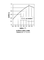
- the thickness ratio of the horizontal axis is the thickness t1 of the first outer fitting step portion 41, the thickness t2 of the second outer fitting step portion 42, and the thickness of the third outer fitting step portion 43.
- the ratio of the bending proof stress of the part 41, the 2nd external fitting step part 42, and the 3rd external fitting step part 43 is represented.
- FIG. 20 the thickness ratio of the horizontal axis is the thickness t1 of the first outer fitting step portion 41, the thickness t2 of the second outer fitting step portion 42, and the thickness of the third outer fitting step portion 43.
- FIG. 20 shows the relationship between the bending strength ratio and the plate thickness ratio when the relationship of / 8 is satisfied.
- FIG. 20 shows the plate thickness D of the external fitting excess length portion 35 and the external fitting of each external fitting step portion 4.
- the first outer fitting is performed.
- the bending strength of the step portion 41 can be equal to or higher than the bending strength of the fourth external fitting step portion 44.
- ht1 to ht4 D / 8
- the plate thickness t1 of the outer fitting valley portion 33 of the first outer fitting step portion 41 is in the range of 0.55T to 0.70T
- the bending strength ratio of the first outer fitting step portion 41 is about 1.2 to 1.3, and the bending strength of the first outer fitting step portion 41 becomes very high. Further, as shown in FIG.
- the plate thickness t2 of the outer fitting valley portion 33 of the second outer fitting step portion 42 is 0.65T to 0.80T.
- the bending strength ratio of the second outer fitting step portion 42 is about 1.1 to 1.2
- the plate thickness t3 of the outer fitting valley portion 33 of the third outer fitting step portion 43 is 0.85 T to 0.
- the bending strength ratio of the third outer fitting step portion 43 is about 1.1.
- the thickness t1 of the inner fitting valley portion 53 is 0.50T to 0.80T
- the thickness t2 of the inner fitting valley portion 53 of the second inner fitting step portion 62 is 0.60T to 0.90T
- the third inner fitting can be improved by setting the thickness t3 of the internally fitted valley portion 53 of the step portion 63 to be 0.80T to 0.95T.
- the outer fitting step portion 4 and the inner fitting step portion 6 have different radii from the central axis in the axial direction Y of the steel pipe pile. Assuming that the areas engaged with each other in the axial direction Y are equal, the inner fitting step 6 has a slightly larger plate thickness.
- the number of stages may be 3, respectively.
- the plate thickness t3 of the external fitting valley portion 33 of the third external fitting step portion 43 is T
- the plate thickness t1 of the external fitting valley portion 33 of the first external fitting step portion 41 is as shown in FIG.
- the first external fitting step portion 41 and the second external fitting step portion 41 can be made larger than the bending strength of the third outer fitting step portion 43 closest to the first steel pipe pile 1.
- the number of steps of the outer fitting step portion 4 and the inner fitting step portion 6 may be two.
- the plate thickness t2 of the external fitting valley portion 33 of the second external fitting step portion 42 closest to the first steel pipe pile 1 is T
- the external fitting of the first external fitting step portion 41 is shown in FIG.
- the bending strength of the first external fitting step 41 is the bending strength of the second external fitting step 42 closest to the first steel pipe pile 1.
- the number of steps of the outer fitting step portion 4 and the inner fitting step portion 6 may be six.
- the outer fitting end portion 3 is, in order from the distal end side to the proximal end side of the outer fitting end portion 3, the first outer fitting step portion 41, the second outer fitting step portion 42, the third outer fitting step portion 43, It has the 4th external fitting step part 44, the 5th external fitting step part 45, and the 6th external fitting step part 46.
- the thickness t6 of the sixth outer fitting step portion 46 is T
- the thickness t1 of the outer fitting valley portion 33 of the first outer fitting step portion 41 is 0.35T.
- the plate thickness t2 of the external fitting valley portion 33 of the second external fitting step portion 42 is 0.45T to 0.75T
- the plate thickness t3 of the external fitting valley portion 33 of the third external fitting step portion 43 is 0. .55T to 0.80T
- the plate thickness t4 of the external fitting valley portion 33 of the fourth external fitting step portion 44 is 0.70T to 0.90T
- the plate thickness of the external fitting valley portion 33 of the fifth external fitting step portion 45 When t5 is in the range of 0.80T to 0.95T, the outer fitting step portion 4 (the first outer fitting step portion 41, the second outer fitting step portion 42, the third outer fitting step except the sixth outer fitting step portion 46).
- the bending strength of the step portion 43, the fourth outer fitting step portion 44, and the fifth outer fitting step portion 45 can be made larger than the bending strength of the sixth outer fitting step portion 46.
- FIG. 27 shows the state of the outer fitting valley portion 33 of the first outer fitting step portion 41 when the bending strength ratio of the first outer fitting step portion 41 is maximized when the number of steps of the outer fitting step portion 4 is 2 to 9.
- Plate thickness ratio plate thickness t1 of the external fitting valley portion 33 of the first external fitting step portion 41 with respect to the plate thickness T of the external fitting valley portion 33 of the external fitting step portion 4 closest to the first steel pipe pile
- FIG. 27 shows the state of the outer fitting valley portion 33 of the first outer fitting step portion 41 when the bending strength ratio of the first outer fitting step portion 41 is maximized when the number of steps of the outer fitting step portion 4 is 2 to 9.
- Plate thickness ratio plate thickness t1 of the external fitting valley portion 33 of the first external fitting step portion 41 with respect to the plate thickness T of the external fitting valley portion 33 of the external fitting step portion 4 closest to the first steel pipe pile
- the relationship with the number of stages of the unit 4 is shown.
- the quadrangular shape is the thickness D of the external fitting extra length portion 35 and the height of the external fitting mountain portion 31 (ht1, ht2,..., Htn: n is the number of steps of the external fitting step portion 4).
- ht1 to htn D / 3
- the plate thickness ratio of the first outer fitting step portion 41 when the bending strength ratio of the first outer fitting step portion 41 is maximized is Fluctuates in the range of about 0.36 to 0.64.
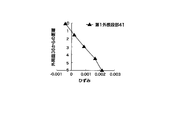
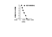
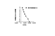
- FIGS. 28A to 28D show the results of FEM analysis at each of the external fitting step portions 4 of the joint structure 7 (when the number of steps of the external fitting step portion 4 is 4).
- FIG. 28A to FIG. 28D show the distance from the outer peripheral surface 36 (see FIG. 17) of the outer fitting valley portion 33 in each outer fitting step portion 4 (41, 42, 43, 44), and the outer The relationship with the distortion of the axial center orthogonal direction X of the fitting valley part 33 is shown.
- 28A shows a case where the thickness t1 [mm] of the external fitting valley portion 33 of the first external fitting step portion 41 is 6, and
- FIG. 28B shows the external fitting valley portion 33 of the second external fitting step portion 42.
- FIG. The case where the plate thickness t4 [mm] of the outer fitting valley portion 33 of the four outer fitting step portion 44 is 12 is shown.
- this FEM analysis on the premise of a large deformation considering geometric nonlinearity, one end of the steel pipe pile is fixed and the other end of the steel pipe pile is forcedly displaced. As material characteristics of the internal fitting end portion 5, the Young's modulus and Poisson's ratio are set to be the same as those of the steel pipe pile.
- each outer fitting step portion 4 has a stress distribution with a linear gradient that minimizes the distortion of the outer peripheral surface 36 of the outer fitting end portion 3. That is, the outer fitting valley portion 33 causes the bending stress at each outer fitting step portion 4 so that the strain at the position farthest from the outer peripheral surface 36 of the outer fitting end portion 3 in the axial center orthogonal direction X becomes the maximum value. bear.
- the bending strength and the bending load ratio are balanced in each of the external fitting stepped portions 4, so that the conventional straight joint structure 90 (see FIG. 30A) or the conventional As compared with the steel pipe pile joint structure 98 (see FIG. 30B), the maximum bending strength can be obtained while reducing the amount of steel used.
- the weight (volume) and bending proof stress of steel materials etc. are appropriate, without producing a useless part in the plate
- the joint structure 7 by setting the plate thickness t ⁇ b> 1 of the first outer fitting step portion 41 to the predetermined range described above, the weight and bending strength of the steel material or the like can be appropriately set, and the joint structure 7 It is possible to improve the design accuracy and facilitate the design of the plate thickness.
- the external fitting end portion 3 or the inner end portion of the end portion of the first steel pipe pile 1 or the second steel pipe pile 2 itself is cut.
- a fitting end 5 may be provided.
- the inner fitting end part 5 may be provided in the 1st steel pipe pile 1
- the outer fitting end part 3 may be provided in the 2nd steel pipe pile 2.
- the present invention it is possible to reduce the labor of rotating the steel pipe pile, avoid an increase in the thickness of the steel pipe pile more than necessary, and provide sufficient tensile and compressive strength at the outer fitting end and the inner fitting end.
- the joint structure of the steel pipe pile which can be provided can be provided. Therefore, the present invention has sufficient industrial applicability.
Landscapes
- Engineering & Computer Science (AREA)
- Structural Engineering (AREA)
- Life Sciences & Earth Sciences (AREA)
- General Life Sciences & Earth Sciences (AREA)
- Mining & Mineral Resources (AREA)
- Paleontology (AREA)
- Civil Engineering (AREA)
- General Engineering & Computer Science (AREA)
- Piles And Underground Anchors (AREA)
Abstract
第1鋼管杭と第2鋼管杭とを直列に接合する、鋼管杭の継手構造であって、第1鋼管杭の一端に設けられ、複数の外嵌段部を有する外嵌端部と、前記第2鋼管杭の一端に設けられ、複数の内嵌段部を有する内嵌端部とを備え、前記第1鋼管杭に近い外嵌段部であるほど外嵌谷部の板厚が大きく形成され、前記第2鋼管杭に近い内嵌段部であるほど内嵌谷部の板厚が大きく形成され、各外嵌段部における外嵌山部の個数、および各内嵌段部における内嵌山部の個数がそれぞれ8以上であり、前記外嵌端部および前記内嵌端部の少なくとも一方において、所定の関係式が満足される。
Description
本発明は、鋼管杭の継手構造に関する。
本願は、2014年7月24日に日本に出願された特願2014-150437号に基づき優先権を主張し、その内容をここに援用する。
本願は、2014年7月24日に日本に出願された特願2014-150437号に基づき優先権を主張し、その内容をここに援用する。
従来から、複数の鋼管杭を機械式継手で軸心方向に連結させることを目的として、特許文献1および2に開示される鋼管杭の継手構造が提案されている。
特許文献1に開示された鋼管杭の継手構造では、軸心方向に隣接する第1杭及び第2杭に、互いに嵌合自在な一対の外嵌端部と内嵌端部とが各別に形成されている。そして、外嵌端部及び内嵌端部に周方向に沿って設けられた係合部および被係合部が、外嵌端部に内嵌端部を挿入させた状態で軸心回りに相対回転させることで互いに係合する。この特許文献1に開示された鋼管杭の継手構造では、前記係合部および前記被係合部が、周方向に沿ってそれぞれ4つ設けられている。
特許文献2に開示された鋼管杭の継手構造では、軸心方向に隣接する第1杭及び第2杭に、互いに嵌合自在な一対の外嵌端部と内嵌端部とが各別に形成されている。そして、外嵌端部及び内嵌端部に周方向に沿って設けられた係合凸部および被係合凸部が、外嵌端部に内嵌端部を挿入させた状態で軸心回りに相対回転させることで互いに係合し合う。この特許文献2に開示された鋼管杭の継手構造では、前記係合凸部および前記被係合凸部が、周方向に沿ってそれぞれ4つ設けられている。また、外嵌端部が先端部側に設けられた係合凸部の形成箇所ほど基端部側に設けられた係合凸部の形成箇所よりも大径に形成されて、内嵌端部が先端部側に設けられた被係合凸部の形成箇所ほど基端部側に設けられた被係合凸部の形成箇所よりも小径に形成されている。
しかしながら、特許文献1に開示された鋼管杭の継手構造では、軸心方向の引張力が作用した際に、外嵌端部および内嵌端部の基端側から先端側に向けて、引張力が低下するにも関わらず、外嵌端部および内嵌端部の板厚が同一とされている。このため、特許文献1に開示された鋼管杭の継手構造は、特に、外嵌端部及び内嵌端部の先端側の板厚に無駄な部分が多くなり、必要以上に板厚が増加してコスト上昇を招くという問題点があった。
また、特許文献2に開示された鋼管杭の継手構造では、軸心方向の引張力が作用した際に、外嵌端部及び内嵌端部の基端側から先端側に向けて、引張力が低下することに対応させて、外嵌端部及び内嵌端部の板厚が基端側から先端側に向けて徐々に小さくされている。そのため、外嵌端部及び内嵌端部の先端側ほど板厚が薄くなり、引張力が作用した際に、径方向の変形が大きくなるという問題点があった。
さらに、特許文献1および特許文献2の鋼管杭の継手構造では、係合部(係合凸部)および被係合部(被係合凸部)の周方向における個数が4つであり、第1杭および第2杭を互いに連結させる際の嵌合角(回転角)が大きくなり、連結作業に手間がかかるという問題点があった。この問題点を回避するための一案として、係合部および被係合部の周方向における個数を多くすること(例えば、上記の個数を8つ)が考えられる。この場合、嵌合角を小さくすることができるため、第1杭および第2杭の連結作業の手間を低減することが可能となる。
しかしながら、係合部(または被係合部)の個数を多くすると、周方向に隣り合う係合部間の間隔が狭くなり、圧縮力が作用した際に応力が集中する箇所が生じてしまい、圧縮耐力が低下するおそれがある。
しかしながら、係合部(または被係合部)の個数を多くすると、周方向に隣り合う係合部間の間隔が狭くなり、圧縮力が作用した際に応力が集中する箇所が生じてしまい、圧縮耐力が低下するおそれがある。
本発明は、上記事情に鑑みてなされたものであり、鋼管杭の回転作業の手間を低減するとともに、鋼管杭の必要以上の板厚増加を回避して、外嵌端部及び内嵌端部に十分な引張耐力および圧縮耐力を付与することのできる、鋼管杭の継手構造を提供することを目的とする。
上記課題を解決するために、本発明は以下を採用した。
(1)本発明の第一の態様は、第1鋼管杭と第2鋼管杭とを直列に接合する、鋼管杭の継手構造である。この鋼管杭の継手構造は、前記第1鋼管杭の一端に設けられ、前記第1鋼管杭の軸心方向に沿って複数の外嵌段部が形成された外嵌端部と;前記第2鋼管杭の一端に設けられてかつ、前記外嵌端部に挿入されるとともに、前記第2鋼管杭の軸心方向に沿って複数の内嵌段部が形成された内嵌端部と;を備え、前記複数の外嵌段部のそれぞれが、その内周面から前記第1鋼管杭の径方向内側へ向かって突出してかつ、前記第1鋼管杭の周方向に沿って設けられた複数の外嵌山部と、前記第1鋼管杭の周方向において互いに隣り合う前記外嵌山部の間に形成された複数の外嵌溝部と、前記内周面において前記各外嵌山部に隣接してかつ前記第1鋼管杭に近い基端側に形成された外嵌谷部と、を有し、前記複数の内嵌段部のそれぞれが、その外周面から前記第2鋼管杭の径方向外側へ向かって突出してかつ、前記第2鋼管杭の周方向に沿って設けられた複数の内嵌山部と、前記第2鋼管杭の周方向において互いに隣り合う前記内嵌山部の間に形成された複数の内嵌溝部と、前記外周面において前記各内嵌山部に隣接してかつ前記第2鋼管杭に近い基端側に形成された内嵌谷部と、を有し、前記複数の外嵌段部では、前記第1鋼管杭に近い外嵌段部であるほど前記外嵌谷部の板厚が大きく形成され、前記複数の内嵌段部では、前記第2鋼管杭に近い内嵌段部であるほど前記内嵌谷部の板厚が大きく形成され、前記各外嵌段部における前記複数の外嵌山部の個数、および前記各内嵌段部における前記複数の内嵌山部の個数が、それぞれ8以上であり、前記第1鋼管杭から最も遠い外嵌段部である第1外嵌段部、および前記第2鋼管杭から最も遠い内嵌段部である第1内嵌段部において、前記第1鋼管杭の軸心方向における前記外嵌山部の長さと前記外嵌谷部の長さとの和、および前記第2鋼管杭の軸心方向における前記内嵌山部の長さと前記内嵌谷部の長さとの和をそれぞれLg1と定義し、前記第1鋼管杭の軸心方向における前記外嵌山部の長さ、および前記第2鋼管杭の軸心方向における前記内嵌山部の長さをそれぞれLm1と定義し、前記外嵌溝部および前記内嵌溝部の周方向における幅をC2と定義し、さらに、前記第1外嵌段部に隣接する第2外嵌段部、および前記第1内嵌段部に隣接する第2内嵌段部において、前記第1鋼管杭の軸心方向における前記外嵌山部の長さ、および前記第2鋼管杭の軸心方向における前記内嵌山部の長さをそれぞれLm2と定義したとき、前記外嵌端部および前記内嵌端部の少なくとも一方が、下記の式(A)および式(B)を満足する。
C2/2≧Lg1 ・・・式(A)
Lm1>Lm2 ・・・式(B)
(2)上記(1)に記載の態様において、前記複数の外嵌段部と前記複数の内嵌段部との間で互いに当接する当接面のうち、前記第1外嵌段部において圧縮力を負担させる圧縮側当接面の圧縮面積、および前記第1内嵌段部において圧縮力を負担させる圧縮側当接面の圧縮面積をそれぞれAc1と定義し、前記第2外嵌段部において圧縮力を負担させる圧縮側当接面の圧縮面積、および前記第2内嵌段部において圧縮力を負担させる圧縮側当接面の圧縮面積をそれぞれAc2と定義し、さらに、前記第2外嵌段部および前記第2内嵌段部において、前記第1鋼管杭の軸心方向における前記外嵌山部の長さと前記外嵌谷部の長さとの和、および前記第2鋼管杭の軸心方向における前記内嵌山部の長さと前記内嵌谷部の長さとの和をそれぞれLg2と定義したとき、前記外嵌端部および前記内嵌端部の少なくとも一方が、下記の式(C)を満足してもよい。
Lm1≧(Ac1/Ac2)×Lg2 ・・・式(C)
(3)上記(1)または(2)に記載の態様において、以下のように構成してもよい:前記複数の外嵌段部の個数が4であり、前記第1外嵌段部の前記外嵌谷部の板厚が、前記第1鋼管杭に最も近い外嵌段部の前記外嵌谷部の板厚の50%以上80%以下である。
(4)上記(1)または(2)に記載の態様において、以下のように構成してもよい:前記複数の外嵌段部の個数が3であり、前記第1外嵌段部の前記外嵌谷部の板厚が、前記第1鋼管杭に最も近い外嵌段部の前記外嵌谷部の板厚の60%以上80%以下である。
(5)上記(1)または(2)に記載の態様において、以下のように構成してもよい:前記複数の外嵌段部の個数が2であり、前記第1外嵌段部の前記外嵌谷部の板厚が、前記第2外嵌段部の前記外嵌谷部の板厚の70%以上90%以下である。
(6)上記(1)または(2)に記載の態様において、以下のように構成してもよい:前記複数の外嵌段部の個数が5以上9以下であり、前記第1外嵌段部の前記外嵌谷部の板厚が、前記第1鋼管杭に最も近い外嵌段部の前記外嵌谷部の板厚の35%以上70%以下である。
(1)本発明の第一の態様は、第1鋼管杭と第2鋼管杭とを直列に接合する、鋼管杭の継手構造である。この鋼管杭の継手構造は、前記第1鋼管杭の一端に設けられ、前記第1鋼管杭の軸心方向に沿って複数の外嵌段部が形成された外嵌端部と;前記第2鋼管杭の一端に設けられてかつ、前記外嵌端部に挿入されるとともに、前記第2鋼管杭の軸心方向に沿って複数の内嵌段部が形成された内嵌端部と;を備え、前記複数の外嵌段部のそれぞれが、その内周面から前記第1鋼管杭の径方向内側へ向かって突出してかつ、前記第1鋼管杭の周方向に沿って設けられた複数の外嵌山部と、前記第1鋼管杭の周方向において互いに隣り合う前記外嵌山部の間に形成された複数の外嵌溝部と、前記内周面において前記各外嵌山部に隣接してかつ前記第1鋼管杭に近い基端側に形成された外嵌谷部と、を有し、前記複数の内嵌段部のそれぞれが、その外周面から前記第2鋼管杭の径方向外側へ向かって突出してかつ、前記第2鋼管杭の周方向に沿って設けられた複数の内嵌山部と、前記第2鋼管杭の周方向において互いに隣り合う前記内嵌山部の間に形成された複数の内嵌溝部と、前記外周面において前記各内嵌山部に隣接してかつ前記第2鋼管杭に近い基端側に形成された内嵌谷部と、を有し、前記複数の外嵌段部では、前記第1鋼管杭に近い外嵌段部であるほど前記外嵌谷部の板厚が大きく形成され、前記複数の内嵌段部では、前記第2鋼管杭に近い内嵌段部であるほど前記内嵌谷部の板厚が大きく形成され、前記各外嵌段部における前記複数の外嵌山部の個数、および前記各内嵌段部における前記複数の内嵌山部の個数が、それぞれ8以上であり、前記第1鋼管杭から最も遠い外嵌段部である第1外嵌段部、および前記第2鋼管杭から最も遠い内嵌段部である第1内嵌段部において、前記第1鋼管杭の軸心方向における前記外嵌山部の長さと前記外嵌谷部の長さとの和、および前記第2鋼管杭の軸心方向における前記内嵌山部の長さと前記内嵌谷部の長さとの和をそれぞれLg1と定義し、前記第1鋼管杭の軸心方向における前記外嵌山部の長さ、および前記第2鋼管杭の軸心方向における前記内嵌山部の長さをそれぞれLm1と定義し、前記外嵌溝部および前記内嵌溝部の周方向における幅をC2と定義し、さらに、前記第1外嵌段部に隣接する第2外嵌段部、および前記第1内嵌段部に隣接する第2内嵌段部において、前記第1鋼管杭の軸心方向における前記外嵌山部の長さ、および前記第2鋼管杭の軸心方向における前記内嵌山部の長さをそれぞれLm2と定義したとき、前記外嵌端部および前記内嵌端部の少なくとも一方が、下記の式(A)および式(B)を満足する。
C2/2≧Lg1 ・・・式(A)
Lm1>Lm2 ・・・式(B)
(2)上記(1)に記載の態様において、前記複数の外嵌段部と前記複数の内嵌段部との間で互いに当接する当接面のうち、前記第1外嵌段部において圧縮力を負担させる圧縮側当接面の圧縮面積、および前記第1内嵌段部において圧縮力を負担させる圧縮側当接面の圧縮面積をそれぞれAc1と定義し、前記第2外嵌段部において圧縮力を負担させる圧縮側当接面の圧縮面積、および前記第2内嵌段部において圧縮力を負担させる圧縮側当接面の圧縮面積をそれぞれAc2と定義し、さらに、前記第2外嵌段部および前記第2内嵌段部において、前記第1鋼管杭の軸心方向における前記外嵌山部の長さと前記外嵌谷部の長さとの和、および前記第2鋼管杭の軸心方向における前記内嵌山部の長さと前記内嵌谷部の長さとの和をそれぞれLg2と定義したとき、前記外嵌端部および前記内嵌端部の少なくとも一方が、下記の式(C)を満足してもよい。
Lm1≧(Ac1/Ac2)×Lg2 ・・・式(C)
(3)上記(1)または(2)に記載の態様において、以下のように構成してもよい:前記複数の外嵌段部の個数が4であり、前記第1外嵌段部の前記外嵌谷部の板厚が、前記第1鋼管杭に最も近い外嵌段部の前記外嵌谷部の板厚の50%以上80%以下である。
(4)上記(1)または(2)に記載の態様において、以下のように構成してもよい:前記複数の外嵌段部の個数が3であり、前記第1外嵌段部の前記外嵌谷部の板厚が、前記第1鋼管杭に最も近い外嵌段部の前記外嵌谷部の板厚の60%以上80%以下である。
(5)上記(1)または(2)に記載の態様において、以下のように構成してもよい:前記複数の外嵌段部の個数が2であり、前記第1外嵌段部の前記外嵌谷部の板厚が、前記第2外嵌段部の前記外嵌谷部の板厚の70%以上90%以下である。
(6)上記(1)または(2)に記載の態様において、以下のように構成してもよい:前記複数の外嵌段部の個数が5以上9以下であり、前記第1外嵌段部の前記外嵌谷部の板厚が、前記第1鋼管杭に最も近い外嵌段部の前記外嵌谷部の板厚の35%以上70%以下である。
本発明の上記各態様によれば、鋼管杭の回転作業の手間を低減するとともに、鋼管杭の必要以上の板厚増加を回避して、外嵌端部及び内嵌端部に十分な引張耐力および圧縮耐力を付与することができる。
以下、本発明の一実施形態に係る鋼管杭の継手構造7(以下、本実施形態に係る継手構造7、または単に継手構造7と呼ぶ場合がある)について、図面を参照しながら詳細に説明する。なお、本明細書及び図面において、実質的に同一の機能構成を有する構成要素については同一符号を付することにより、それらの重複説明を省略する。
尚、以下の説明においては、鋼管杭の軸心延在方向を軸心方向Y、軸心方向Yに直交する方向を軸心直交方向X、鋼管杭の軸心回りの方向を周方向Wと呼称する場合がある。
尚、以下の説明においては、鋼管杭の軸心延在方向を軸心方向Y、軸心方向Yに直交する方向を軸心直交方向X、鋼管杭の軸心回りの方向を周方向Wと呼称する場合がある。
図1は、本実施形態に係る鋼管杭の継手構造7を示す斜視図である。図1に示すように、継手構造7は、地盤上に構築される構造物の基礎杭等において、断面円形状の第1鋼管杭1および第2鋼管杭2を軸心方向Yに沿って互いに連結する機械式継手として用いられる。
継手構造7は、第1鋼管杭1の上端に設けられた中空円柱状の外嵌端部3と、第2鋼管杭2の下端に設けられた中空円柱状の内嵌端部5とを備える。外嵌端部3と内嵌端部5とは互いに嵌合自在な構造を有する。なお、外嵌端部3は溶接等で第1鋼管杭1の上端に接合され、内嵌端部5は溶接等で第2鋼管杭2の下端に接合されている。
継手構造7では、軸心方向Yに沿って並べられた4つ(4段)の外嵌段部4(41、42、43、44)が外嵌端部3に設けられるとともに、軸心方向Yに沿って並べられた4つ(4段)の内嵌段部6(61、62、63、64)が内嵌端部5に設けられている。すなわち、外嵌端部3は、軸心方向Yで先端側から基端側まで、順番に第1外嵌段部41、第2外嵌段部42、第3外嵌段部43、および第4外嵌段部44を有する。同様に、内嵌端部5は、軸心方向Yで先端側から基端側まで、順番に第1内嵌段部61、第2内嵌段部62、第3内嵌段部63、および第4内嵌段部64を有する。
なお、図1において、軸心方向Yの下側(第1鋼管杭1に近い側)が外嵌端部3における基端側であり、軸心方向Yの上側(第2鋼管杭2に近い側)が内嵌端部5における基端側である。また、外嵌端部3および内嵌端部5の基端側と反対の側を、先端側と称する。以後、本明細書における全ての図において同様である。
なお、図1において、軸心方向Yの下側(第1鋼管杭1に近い側)が外嵌端部3における基端側であり、軸心方向Yの上側(第2鋼管杭2に近い側)が内嵌端部5における基端側である。また、外嵌端部3および内嵌端部5の基端側と反対の側を、先端側と称する。以後、本明細書における全ての図において同様である。
4つの外嵌段部4の各々は、外嵌端部3の内壁面(内周面)で第1鋼管杭1の軸心直交方向X(軸心方向Yに対して直交する方向(径方向):図1参照)の中心側(径方向内側)に突出するとともに周方向Wに沿って形成された8個の外嵌山部31と、周方向Wに互いに隣り合う外嵌山部31の間に形成された8個の外嵌溝部32と、軸心方向Yで外嵌山部31に隣接してかつ第1鋼管杭1に近い基端側に形成された外嵌谷部33とを有する。
なお、図1に示すように、各々の外嵌段部4において、外嵌溝部32及び外嵌谷部33は、互いに面一となるように同じ板厚で形成されることが嵌合性及び加工性の観点から好ましい。
なお、図1に示すように、各々の外嵌段部4において、外嵌溝部32及び外嵌谷部33は、互いに面一となるように同じ板厚で形成されることが嵌合性及び加工性の観点から好ましい。
図2は、外嵌端部3を示す図であって、第1鋼管杭1の軸心を含む断面で見た場合の断面図である。図2に示すように、外嵌端部3の4つの外嵌段部4の各々において、外嵌山部31の板厚よりも外嵌溝部32の板厚が小さくされ、外嵌山部31と外嵌溝部32とが周方向Wで交互に形成されている。そして、複数の外嵌山部31が、軸心方向Y及び周方向Wで略一列に配置されている。また、複数の外嵌溝部32が、軸心方向Y及び周方向Wで略一列に配置されている。
外嵌端部3では、第4外嵌段部44の外嵌谷部33の基端側には、外嵌余長部35が形成されている。外嵌余長部35の先端側には、外嵌基端面34が全周に亘って形成されている。なお、この外嵌余長部35が第1鋼管杭1の上端に溶接されることにより、外嵌端部3は第1鋼管杭1に接合される。
外嵌山部31は、周方向Wに所定の幅C1(外嵌山部31の周長)を有するとともに、軸心直交方向Xに所定の高さを有する。また、外嵌溝部32は、周方向Wに所定の幅C2(外嵌溝部32の周長)を有する。
図3は、外嵌端部3を示す部分断面図である。図3に示すように、外嵌谷部33の板厚は、外嵌端部3の基端側に近い外嵌段部4ほど大きく形成されている。すなわち、第1外嵌段部41の外嵌谷部33の板厚は、第2外嵌段部42の外嵌谷部33の板厚よりも小さく、第2外嵌段部42の外嵌谷部33の板厚は、第3外嵌段部43の外嵌谷部33の板厚よりも小さく、第3外嵌段部43の外嵌谷部33の板厚は、第4外嵌段部44の外嵌谷部33の板厚よりも小さく形成されている。
軸心方向Yで最も先端側に位置する第1外嵌段部41の外嵌山部31は、軸心方向Yで長さLm1を有する。また、軸心方向Yで第1外嵌段部41に隣り合う第2外嵌段部42の外嵌山部31は、軸心方向Yで長さLm2を有する。また、軸心方向Yで第2外嵌段部42に隣り合う第3外嵌段部43の外嵌山部31は、軸心方向Yで長さLm3を有する。また、軸心方向Yで第3外嵌段部43に隣り合う第4外嵌段部44の外嵌山部31は、軸心方向Yで長さLm4を有する。
また、外嵌端部3では、中心軸から第1外嵌段部41の外嵌山部31までの半径r41、中心軸から第2外嵌段部42の外嵌山部31までの半径r42、中心軸から第3外嵌段部43の外嵌山部31までの半径r43、および中心軸から第4外嵌段部44の外嵌山部31までの半径r44と定義した場合に、r41>r42>r43>r44の関係が満たされている。
更に、外嵌端部3では、第1外嵌段部41の外嵌山部31で外嵌端部3の基端側の高さをht1、第2外嵌段部42の外嵌山部31で外嵌端部3の基端側の高さをht2、第3外嵌段部43の外嵌山部31で外嵌端部3の基端側の高さをht3、第4外嵌段部44の外嵌山部31で外嵌端部3の基端側の高さをht4と定義した場合に、ht1=ht2=ht3=ht4の関係が満たされている。
また、外嵌端部3では、第1外嵌段部41の外嵌山部31で外嵌端部3の先端側の高さをhc1、第2外嵌段部42の外嵌山部31で外嵌端部3の先端側の高さをhc2、第3外嵌段部43の外嵌山部31で外嵌端部3の先端側の高さをhc3、第4外嵌段部44の外嵌山部31で外嵌端部3の先端側の高さをhc4と定義した場合に、hc2=hc3=hc4の関係が満たされるとともに、hc1<hc2の関係が満たされている。
第1外嵌段部41の外嵌谷部33は、軸心方向Yで長さLv1を有する。第2外嵌段部42の外嵌谷部33は、軸心方向Yで長さLv2を有する。第3外嵌段部43の外嵌谷部33は、軸心方向Yで長さLv3を有する。第4外嵌段部44の外嵌谷部33は、軸心方向Yで長さLv4を有する。
なお、図3において、Lg1は、第1外嵌段部41における外嵌山部31の長さLm1と外嵌谷部33の長さLv1との和であり、Lg2は、第2外嵌段部42における外嵌山部31の長さLm2と外嵌谷部33の長さLv2との和であり、Lg3は、第3外嵌段部43における外嵌山部31の長さLm3と外嵌谷部33の長さLv3との和であり、Lg4は、第4外嵌段部44における外嵌山部31の長さLm4と外嵌谷部33の長さLv4との和である。
内嵌端部5は、図1に示すように、各々の内嵌段部6(61、62、63、64)において、内嵌端部5の外壁面(外周面)で第2鋼管杭2の軸心直交方向Xの外向き(径方向外側)に突出するとともに周方向Wに沿って形成された8個の内嵌山部51と、周方向Wに互いに隣り合う内嵌山部51の間に形成された8個の内嵌溝部52と、軸心方向Yで内嵌山部51に隣接してかつ第2鋼管杭2に近い基端側に形成された内嵌谷部53とを有する。
図1に示すように、各々の内嵌段部6において、内嵌溝部52及び内嵌谷部53は、互いに面一となるように同じ板厚で形成されることが嵌合性及び加工性の観点から好ましい。
図4は、内嵌端部5を示す正面図である。図4に示すように、内嵌端部5の4つの内嵌段部6の各々において、内嵌山部51の板厚よりも内嵌溝部52の板厚が小さくされ、内嵌山部51と内嵌溝部52とが周方向Wで交互に形成されている。そして、複数の内嵌山部51が、軸心方向Y及び周方向Wで略一列に配置されている。また、複数の内嵌溝部52が、軸心方向Y及び周方向Wで略一列に配置されている。
また、内嵌端部5では、第4内嵌段部64の内嵌谷部53の基端側に内嵌余長部55が形成されている。内嵌余長部55の先端側には、内嵌基端面54が全周に亘って形成されている。なお、この内嵌余長部55が第2鋼管杭2の下端に溶接されることにより、内嵌端部5は第2鋼管杭2に接合される。
また、内嵌山部51は、周方向Wに所定の幅C1(内嵌山部51の周長)を有するとともに、軸心直交方向Xに所定の高さを有する。また、内嵌溝部52は、周方向Wに所定の幅C2(内嵌溝部52の周長)を有する。
図5は、内嵌端部5を示す部分断面図である。図5に示すように、内嵌谷部53の板厚は、内嵌端部5の基端側に近い内嵌段部6ほど大きく形成されている。すなわち、第1内嵌段部61の内嵌谷部53の板厚は、第2内嵌段部62の内嵌谷部53の板厚よりも小さく、第2内嵌段部62の内嵌谷部53の板厚は、第3内嵌段部63の内嵌谷部53の板厚よりも小さく、第3内嵌段部63の内嵌谷部53の板厚は、第4内嵌段部64の内嵌谷部53の板厚よりも小さく形成される。
軸心方向Yで最も先端側に位置する第1内嵌段部61の内嵌山部51は、軸心方向Yで長さLm1を有する。また、軸心方向Yで第1内嵌段部61に隣り合う第2内嵌段部62の内嵌山部51は、軸心方向Yで長さLm2を有する。また、軸心方向Yで第2内嵌段部62に隣り合う第3内嵌段部63の内嵌山部51は、軸心方向Yで長さLm3を有する。また、軸心方向Yで第3内嵌段部63に隣り合う第4内嵌段部64の内嵌山部51は、軸心方向Yで長さLm4を有する。
また、内嵌端部5では、中心軸から第1内嵌段部61の内嵌山部51までの半径r61、中心軸から第2内嵌段部62の内嵌山部51までの半径r62、中心軸から第3内嵌段部63の内嵌山部51までの半径r63、中心軸から第4内嵌段部64の内嵌山部51までの半径r64と定義した場合に、r64>r63>r62>r61の関係が満たされている。
更に、内嵌端部5では、第1内嵌段部61の内嵌山部51で内嵌端部5の基端側の高さをht1、第2内嵌段部62の内嵌山部51で内嵌端部5の基端側の高さをht2、第3内嵌段部63の内嵌山部51で内嵌端部5の基端側の高さをht3、第4内嵌段部64の内嵌山部51で内嵌端部5の基端側の高さをht4と定義した場合に、ht1=ht2=ht3=ht4の関係が満たされている。
また、内嵌端部5では、第1内嵌段部61の内嵌山部51で内嵌端部5の先端側の高さをhc1、第2内嵌段部62の内嵌山部51で内嵌端部5の先端側の高さをhc2、第3内嵌段部63の内嵌山部51で内嵌端部5の先端側の高さをhc3、第4内嵌段部64の内嵌山部51で内嵌端部5の先端側の高さをhc4と定義した場合に、hc2=hc3=hc4の関係が満たされるとともに、hc1<hc2の関係が満たされている。
第1内嵌段部61の内嵌谷部53は、軸心方向Yで長さLv1を有する。第2内嵌段部62の内嵌谷部53は、軸心方向Yで長さLv2を有する。第3内嵌段部63の内嵌谷部53は、軸心方向Yで長さLv3を有する。第4内嵌段部64の内嵌谷部53は、軸心方向Yで長さLv4を有する。
なお、図5において、Lg1は、第1内嵌段部61における内嵌山部51の長さLm1と内嵌谷部53の長さLv1との和であり、Lg2は、第2内嵌段部62における内嵌山部51の長さLm2と内嵌谷部53の長さLv2との和であり、Lg3は、第3内嵌段部63における内嵌山部51の長さLm3と内嵌谷部53の長さLv3との和であり、Lg4は、第4内嵌段部64における内嵌山部51の長さLm4と内嵌谷部53の長さLv4との和である。
継手構造7では、第1鋼管杭1と第2鋼管杭2とを同軸に連結するために、図6および図7に示すように、外嵌端部3と内嵌端部5とを互いに嵌合させる。なお、図7は、外嵌端部3の一部を切断した状態を示す斜視図である。
具体的には、まず、図6に示すように、第2鋼管杭2に取り付けられた内嵌端部5を第1鋼管杭1に取り付けられた外嵌端部3に挿入する。なお、各々の内嵌段部6において、内嵌山部51の軸心直交方向Xの高さは、嵌合時に対応する外嵌溝部32の軸心直交方向Xの深さ以下に設定されている。また、外嵌山部31及び内嵌山部51の周方向Wにおける幅C1は、外嵌溝部32及び内嵌溝部52の周方向Wにおける幅C2以下に設定されている。これらにより、内嵌端部5が外嵌端部3に干渉することを避けることができ、内嵌端部5を外嵌端部3に挿入することができる。
具体的には、まず、図6に示すように、第2鋼管杭2に取り付けられた内嵌端部5を第1鋼管杭1に取り付けられた外嵌端部3に挿入する。なお、各々の内嵌段部6において、内嵌山部51の軸心直交方向Xの高さは、嵌合時に対応する外嵌溝部32の軸心直交方向Xの深さ以下に設定されている。また、外嵌山部31及び内嵌山部51の周方向Wにおける幅C1は、外嵌溝部32及び内嵌溝部52の周方向Wにおける幅C2以下に設定されている。これらにより、内嵌端部5が外嵌端部3に干渉することを避けることができ、内嵌端部5を外嵌端部3に挿入することができる。
次に、図7に示すように、外嵌端部3に内嵌端部5を挿入した状態で、第1鋼管杭1と第2鋼管杭2とを軸心回りの周方向Wに相対回転させる。なお、各々の内嵌段部6において、内嵌谷部53の軸心直交方向Xの深さは、嵌合時に対応する外嵌山部31の軸心直交方向Xの高さ以上に設定されている。これにより、外嵌山部31を内嵌谷部53に嵌合可能な構造となる。
上述のように、各々の外嵌段部4では、8個の外嵌山部31が形成され、各々の内嵌段部6では、8個の内嵌山部51が形成されている。これに対して、上記特許文献1に記載の鋼管杭の継手構造では、外嵌山部31に対応する係合部が周方向に4個形成され、内嵌山部51に対応する被係合部が周方向に4個形成されている(特許文献2に記載の鋼管杭の継手構造においても同様)。本実施形態に係る継手構造7では、特許文献1に記載の鋼管杭の継手構造に対して、外嵌山部31および内嵌山部51の個数を多く形成することにより、第1鋼管杭1と第2鋼管杭2とを嵌合させる際の回転角(嵌合角)を小さくすることができるので、鋼管杭1と第2鋼管杭2との嵌合を容易に行うことができる。したがって、第1鋼管杭1と第2鋼管杭2とを連結させる回転作業の手間を低減することができる。
なお、本発明はこの構造のみに限定されず、8個より大きい数の外嵌山部31および内嵌山部51が周方向Wに所定間隔を空けて形成されてもよい。この場合、第1鋼管杭1と第2鋼管杭2とを嵌合させる際の回転角をさらに小さくすることができる。
なお、本発明はこの構造のみに限定されず、8個より大きい数の外嵌山部31および内嵌山部51が周方向Wに所定間隔を空けて形成されてもよい。この場合、第1鋼管杭1と第2鋼管杭2とを嵌合させる際の回転角をさらに小さくすることができる。
ここで、外嵌端部3および内嵌端部5の真円度が、第1鋼管杭1および第2鋼管杭2の直径dのa%以内の場合、軸心直交方向Xにおける、外嵌端部3と内嵌端部5との間のクリアランスcは、c≧(2×d×a/100)/Nであることが好ましい。なお、Nは、各々の外嵌段部4における外嵌山部31の個数、および各々の内嵌段部6における内嵌山部51の個数を表す。この場合、外嵌端部3および内嵌端部5の真円度に起因した、外嵌端部3と内嵌端部5との嵌合時における干渉を避けることができる。
一般的に、上記の真円度は、第1鋼管杭1および第2鋼管杭2の直径dの1%以内であり、また、上記のクリアランスcは、1mm以上で設定される。これらを考慮すると、例えば直径dが400mmの場合、各々の外嵌段部4における外嵌山部31の個数、および各々の内嵌段部6における内嵌山部51の個数を8以上とすることにより、クリアランスcが1mmであっても、外嵌端部3および内嵌端部5の真円度に起因した、外嵌端部3と内嵌端部5との嵌合時における干渉を避けることができる。
一般的に、上記の真円度は、第1鋼管杭1および第2鋼管杭2の直径dの1%以内であり、また、上記のクリアランスcは、1mm以上で設定される。これらを考慮すると、例えば直径dが400mmの場合、各々の外嵌段部4における外嵌山部31の個数、および各々の内嵌段部6における内嵌山部51の個数を8以上とすることにより、クリアランスcが1mmであっても、外嵌端部3および内嵌端部5の真円度に起因した、外嵌端部3と内嵌端部5との嵌合時における干渉を避けることができる。
図8は、外嵌端部3に内嵌端部5を挿入して相対回転させた状態を示す概略断面図である。図8に示すように、内嵌段部6および外嵌段部4において、内嵌山部51の軸心方向Yの長さは、嵌合時に対応する外嵌谷部33の軸心方向Yの長さと略同一に設定されており、外嵌山部31の軸心方向Yの長さは、嵌合時に対応する内嵌谷部53の軸心方向Yの長さと略同一に設定されている。これにより、軸心方向Yで外嵌山部31と内嵌山部51とを係合させることが可能となる。そして、外嵌山部31と内嵌山部51とが、軸心方向Yで互いに当接面8で当接して係合することにより、第1鋼管杭1と第2鋼管杭2とを、軸心方向Yで互いに離間させないように連結することができる。
また、図8に示すように、第1鋼管杭1と第2鋼管杭2とを連結させた状態で、第1鋼管杭1及び第2鋼管杭2から外嵌端部3及び内嵌端部5に、軸心方向Yの引張力T及び圧縮力Pが作用する際、引張力T及び圧縮力Pに対して、外嵌山部31と内嵌山部51とが軸心方向Yの当接面8で抵抗する。
継手構造7では、各々の外嵌段部4及び各々の内嵌段部6において、外嵌山部31と内嵌山部51とが互いに当接される当接面8のうち、外嵌端部3の基端側及び内嵌端部5の基端側が引張力Tを負担する引張側当接面81であり、外嵌端部3の先端側及び内嵌端部5の先端側が圧縮力Pを負担する圧縮側当接面86である。
そして、図9に示すように、第1外嵌段部41の外嵌山部31と第4内嵌段部64の内嵌山部51とが、引張側当接面81で引張面積At1(At1≒ht1×C1)を有し、第2外嵌段部42の外嵌山部31と第3内嵌段部63の内嵌山部51とが、引張側当接面81で引張面積At2(At2≒ht2×C1)を有する。
また、第1外嵌段部41の外嵌山部31と内嵌基端面54とが、圧縮側当接面86で圧縮面積Ac1(Ac1≒hc1×C1)を有し、第2外嵌段部42の外嵌山部31と第4内嵌段部64の内嵌山部51とが、圧縮側当接面86で圧縮面積Ac2(Ac2≒hc2×C1)を有する。
また、第1外嵌段部41の外嵌山部31と内嵌基端面54とが、圧縮側当接面86で圧縮面積Ac1(Ac1≒hc1×C1)を有し、第2外嵌段部42の外嵌山部31と第4内嵌段部64の内嵌山部51とが、圧縮側当接面86で圧縮面積Ac2(Ac2≒hc2×C1)を有する。
同様に、第1内嵌段部61の内嵌山部51と第4外嵌段部44の外嵌山部31とが、引張側当接面81で引張面積At1(At1≒ht1×C1)を有し、第2内嵌段部62の内嵌山部51と第3外嵌段部43の外嵌山部31とが、引張側当接面81で引張面積At2(At2≒ht2×C1)を有する。
また、第1内嵌段部61の内嵌山部51と外嵌基端面34とが、圧縮側当接面86で圧縮面積Ac1(Ac1≒hc1×C1)を有し、第2内嵌段部62の内嵌山部51と第4外嵌段部44の外嵌山部31とが、圧縮側当接面86で圧縮面積Ac2(Ac2≒hc2×C1)を有する。
また、第1内嵌段部61の内嵌山部51と外嵌基端面34とが、圧縮側当接面86で圧縮面積Ac1(Ac1≒hc1×C1)を有し、第2内嵌段部62の内嵌山部51と第4外嵌段部44の外嵌山部31とが、圧縮側当接面86で圧縮面積Ac2(Ac2≒hc2×C1)を有する。
図10は、外嵌端部3の第1外嵌段部41および第2外嵌段部42を示す部分拡大正面図である。なお、図10は、第1外嵌段部41に圧縮力Pが作用した状態を示している。図10に示すように、第1外嵌段部41の外嵌山部31に軸心方向Yの圧縮力Pが作用することにより、第1外嵌段部41の外嵌山部31から外嵌溝部32に向けて、所定の分散範囲Rで圧縮力Pが応力分散する。この分散範囲Rは、第1外嵌段部41の外嵌山部31及び外嵌谷部33の側辺s1と、側辺s1の基端点gbから周方向Wで側辺s1に対して垂直に延びた下辺s2と、側辺s1の先端点gaから外嵌端部3の基端側に向けて角度αで傾斜した斜辺s3とによって、略直角三角形状に形成される。なお、角度αは、圧縮力Pが応力分散するときの角度であって、α=45°である。
周方向Wで隣り合う外嵌山部31に作用した圧縮力Pの分散範囲Rが、外嵌溝部32で重なり合う場合には、この重なり合う部分に圧縮力Pの応力分散が集中することになる。そこで、継手構造7では、軸心方向Yにおける第1外嵌段部41の長さLg1(外嵌山部31の長さLm1と外嵌谷部33の長さLv1との和)と、外嵌溝部32の周方向Wの幅C2とが下記式(1)を満足するように設定される。
C2/2≧Lg1 ・・・式(1)
C2/2≧Lg1 ・・・式(1)
第1外嵌段部41において上記式(1)を満足することにより、圧縮力Pの分散範囲Rの下辺s2が外嵌溝部32の周方向Wの幅C2の半分以下の長さとなる。そのため、周方向Wで隣り合う外嵌山部31に作用した圧縮力Pの分散範囲Rが、外嵌溝部32で互いに重なり合うことを防止することができる。したがって、第1外嵌段部41に圧縮力が作用した際の応力集中を防止することができるので、第1外嵌段部41の板厚を増加させることなく、継手構造7の圧縮耐力を向上させることができる。
なお、継手構造7では、外嵌段部4のうち、最も板厚の薄い第1外嵌段部41が上記式(1)を満足するが、第2外嵌段部42、第3外嵌段部43、および第4外嵌段部44において、上記式(1)と同様の関係式を満足するように、Lg2~Lg4を設定してもよい。
図11は、内嵌端部5の第1内嵌段部61および第2内嵌段部62を示す部分拡大正面図である。なお、図11は、第1内嵌段部61に圧縮力Pが作用した状態を示している。図10に示した外嵌端部3の場合と同様に、内嵌端部5は、図11に示すように、第1内嵌段部61の内嵌山部51に軸心方向Yの圧縮力Pが作用することにより、第1内嵌段部61の内嵌山部51から内嵌溝部52に向けて、所定の分散範囲Rで圧縮力Pが応力分散する。この分散範囲Rは、第1内嵌段部61の内嵌山部51及び内嵌谷部53の側辺s1と、側辺s1の基端点gbから周方向Wで側辺s1に対して垂直に延びた上辺s2と、側辺s1の先端点gaから内嵌端部5の基端側に向けて角度αで傾斜した斜辺s3とによって、略直角三角形状に形成される。角度αは、第1内嵌段部61の内嵌山部51に作用した軸心方向Yの圧縮力Pが応力分散するときの角度であって、α=45°である。
第1内嵌段部61においても、上記式(1)を満足することにより、圧縮力Pの分散範囲Rの上辺s2が内嵌溝部52の周方向Wの幅C2の半分以下の長さとなる。そのため、周方向Wで隣り合う内嵌山部51に作用した圧縮力Pの分散範囲Rが、内嵌溝部52で互いに重なり合うことを防止することができる。したがって、第1内嵌段部61に圧縮力が作用した際の応力集中を防止することができるので、第1内嵌段部61の板厚を増加させることなく、継手構造7の圧縮耐力を向上させることができる。
上述のように、継手構造7では、第1外嵌段部41および第1内嵌段部61において、上記式(1)を満足することにより、外嵌端部3および内嵌端部5の板厚を増大させることなく、圧縮力Pに対して十分な圧縮耐力を付与することができる。なお、継手構造7は、第1外嵌段部41および第1内嵌段部61の少なくとも一方において、上記式(1)を満足する構造としてもよい。
図12Aは、外嵌端部3の第1外嵌段部41および第2外嵌段部42を示す部分断面図であり、図12Bは、内嵌端部5の第1内嵌段部61および第2内嵌段部62を示す部分断面図である。図12Aに示すように、外嵌端部3では、第1外嵌段部41の外嵌山部31の軸心方向Yの長さLm1と、第2外嵌段部42の外嵌山部31の軸心方向Yの長さLm2とが、下記式(2)を満足するように設定される。
Lm1>Lm2 ・・・式(2)
Lm1>Lm2 ・・・式(2)
同様に、図12Bに示すように、内嵌端部5では、第1内嵌段部61の内嵌山部51の軸心方向Yの長さLm1と、第2内嵌段部62の内嵌山部51の軸心方向Yの長さLm2とが、上記式(2)を満足するように設定される。
ここで、外嵌端部3および内嵌端部5に上記式(2)を用いる理由について説明する。図29Aおよび図29Bは、上記式(2)を満足しない鋼管杭の継手構造9を示す概略断面図である。図29Aおよび図29Bに示すように、先端側の第1段部91の山部95における軸心方向Yの長さLm1が、第2段部92の山部95の軸心方向Yの長さLm2以下の場合、第1段部91の山部95の表面積が小さくなるため、引張力Tが伝達されることによって作用する軸心直交方向Xの外側に向けた応力Fが大きくなる。
このように引張力Tが作用した際の応力Fが大きい場合、外嵌端部3では、第2外嵌段部42よりも第1外嵌段部41の方が軸心直交方向Xの板厚が薄く、さらに、第1外嵌段部41が第1鋼管杭1の上端部に拘束されないため(図8参照)、第1外嵌段部41が軸心直交方向Xの外側に向けて拡がるフープ変形が、外嵌端部3に生じるおそれがある。
また、内嵌端部5でも、第2内嵌段部62よりも第1内嵌段部61の方が軸心直交方向Xの板厚が薄く、さらに、第1内嵌段部61が第2鋼管杭2の下端部に拘束されないため、第1内嵌段部61が軸心直交方向Xの内側に向けて潰れる座屈変形が、内嵌端部5に生じるおそれがある。
このように引張力Tが作用した際の応力Fが大きい場合、外嵌端部3では、第2外嵌段部42よりも第1外嵌段部41の方が軸心直交方向Xの板厚が薄く、さらに、第1外嵌段部41が第1鋼管杭1の上端部に拘束されないため(図8参照)、第1外嵌段部41が軸心直交方向Xの外側に向けて拡がるフープ変形が、外嵌端部3に生じるおそれがある。
また、内嵌端部5でも、第2内嵌段部62よりも第1内嵌段部61の方が軸心直交方向Xの板厚が薄く、さらに、第1内嵌段部61が第2鋼管杭2の下端部に拘束されないため、第1内嵌段部61が軸心直交方向Xの内側に向けて潰れる座屈変形が、内嵌端部5に生じるおそれがある。
上記に対して、本実施形態に係る継手構造7では、図12Aおよび図12Bに示すように、第1外嵌段部41の外嵌山部31、および第1内嵌段部61の内嵌山部51が上記式(2)を満足することにより、Lm1がLm2よりも長くなる。その結果、第1外嵌段部41の外嵌山部31、および第1内嵌段部61の内嵌山部51の軸心方向Yの表面積が大きくなり、引張力Tが作用した際の応力Fを小さくすることができる。したがって、引張力が作用した際に、第1外嵌段部41のフープ変形、および第1内嵌段部61の座屈変形を防止することができるので、引張耐力を向上させることができる。
上述のように、本実施形態に係る継手構造7では、図10~図12Bに示すように、第1外嵌段部41の外嵌山部31および第1内嵌段部61の内嵌山部51の長さLm1が、上記式(2)を満足することにより、引張力Tに対して十分な引張耐力を付与することが可能となる。さらに、第1外嵌段部41又は第1内嵌段部61の長さLg1が、上記式(1)を満足することにより、外嵌端部3又は内嵌端部5の加工コストまたは材料コスト等の製造コストの増大を抑制すると同時に、圧縮力Pに対して十分な圧縮耐力を付与することが可能となる。
次に、継手構造7の当接面8に関して説明する。外嵌端部3及び内嵌端部5は、打撃ハンマー等により鋼管杭が高荷重下で打設される場合に、引張力Tよりも圧縮力Pの方が過大になる。このような打撃ハンマー等による過大な圧縮力Pが作用した場合、図13に示すように、外嵌端部3及び内嵌端部5では、第2外嵌段部42から第4外嵌段部44に向けて、及び、第2内嵌段部62から第4内嵌段部64に向けて傾斜した仮想せん断面Sにおいて、過大な圧縮力Pによるせん断破壊が生じることが想定される。
過大な圧縮力Pに対して、第1外嵌段部41及び第1内嵌段部61では、図14Aおよび図14Bに示すように、第1外嵌段部41の外嵌山部31の長さLm1、および第1内嵌段部61の内嵌山部51の長さLm1の範囲のみのせん断面積でせん断抵抗する。一方、第2外嵌段部42及び第2内嵌段部62では、仮想せん断面Sの範囲のせん断面積でせん断抵抗するため、せん断抵抗する際のせん断面の軸心方向Yの長さは、第2外嵌段部42の長さLg2、又は、第2内嵌段部62の長さLg2に近似される。
また、第2外嵌段部42の外嵌山部31、及び第2内嵌段部62の内嵌山部51に伝達される圧縮力P2は、圧縮側当接面86の圧縮面積に比例するため、第1外嵌段部41の外嵌山部31及び第1内嵌段部61の内嵌山部51に伝達される圧縮力P1、圧縮面積Ac1、及び圧縮面積Ac2から、下記式(3)で表される。
P2=(Ac2/Ac1)×P1 ・・・式(3)
P2=(Ac2/Ac1)×P1 ・・・式(3)
ここで、第2外嵌段部42の板厚よりも第1外嵌段部41の板厚が薄いことを考慮すると、過大な圧縮力Pに対する圧縮耐力を向上させためには、第1外嵌段部41のせん断抵抗力を第2外嵌段部42のせん断抵抗力以上に設定する必要がある。そのため、継手構造7では、外嵌端部3および内嵌端部5において、第1外嵌段部41の外嵌山部31の長さLm1、および第1内嵌段部61の内嵌山部51の長さLm1と、第2外嵌段部42および第2内嵌段部62の長さLg2とが、下記の式(4)を満足するように設定される。
Lm1/P1≧Lg2/P2 ・・・式(4)
P1:第1外嵌段部41の外嵌山部31または第1内嵌段部61の内嵌山部51に伝達される圧縮力
P2:第2外嵌段部42の外嵌山部31または第2内嵌段部62の内嵌山部51に伝達される圧縮力
P1:第1外嵌段部41の外嵌山部31または第1内嵌段部61の内嵌山部51に伝達される圧縮力
P2:第2外嵌段部42の外嵌山部31または第2内嵌段部62の内嵌山部51に伝達される圧縮力
そして、上記式(3)および式(4)により、外嵌端部3では、図14Aに示すように、第1外嵌段部41の外嵌山部31の長さLm1が、第2外嵌段部42の長さLg2に対して、下記式(5)を満足するように設定される。同様に、図14Bに示すように、内嵌端部5では、第1内嵌段部61の内嵌山部51の長さLm1が、第2内嵌段部62の長さLg2に対して下記式(5)を満足するように設定される。
Lm1≧(Ac1/Ac2)×Lg2 ・・・式(5)
Lm1≧(Ac1/Ac2)×Lg2 ・・・式(5)
外嵌端部3及び内嵌端部5において、上記式(5)を満足することにより、第1外嵌段部41のせん断抵抗力を第2外嵌段部42のせん断抵抗力以上に設定することができ、過大な圧縮力Pに対する圧縮耐力を向上させることができる。すなわち、継手構造7では、過大な圧縮力Pが伝達されたときに、圧縮力P1に対する第1外嵌段部41の外嵌山部31又は第1内嵌段部61の内嵌山部51のせん断抵抗力が、圧縮力P2に対する第2外嵌段部42又は第2内嵌段部62のせん断抵抗力以上の大きさとなり、全ての外嵌段部4又は内嵌段部6で所定のせん断抵抗力を確保して、過大な圧縮力Pに対する圧縮耐力を向上させることが可能となる。
なお、外嵌端部3において、第1外嵌段部41の外嵌山部31と第4内嵌段部64の内嵌山部51との引張面積At1と、第1外嵌段部41の外嵌山部31と内嵌基端面54との圧縮面積Ac1とが略同一であるため、第1外嵌段部41の外嵌山部31の長さLm1は、上記式(5)を用いて下記式(6)により表される。また、内嵌端部5において、第1内嵌段部61の内嵌山部51と第4外嵌段部44の外嵌山部31との引張面積At1と、第1内嵌段部61の内嵌山部51と外嵌基端面34との圧縮面積Ac1とが略同一であるため、第1内嵌段部61の内嵌山部51の長さLm1は、上記式(5)を用いて下記式(6)により表される。
Lm1≧(At1/Ac2)×Lg2 ・・・式(6)
Lm1≧(At1/Ac2)×Lg2 ・・・式(6)
また、外嵌端部3において、第2外嵌段部42の外嵌山部31の長さLm2と、第2外嵌段部42の外嵌谷部33の長さLv2とが略同一の場合、第1外嵌段部41の外嵌山部31の長さLm1が、下記式(7)および式(8)により表される。また、内嵌端部5において、第2内嵌段部62の内嵌山部51の長さLm2と、第2内嵌段部62の内嵌谷部53の長さLv2とが略同一の場合、第1内嵌段部61の内嵌山部51の長さLm1が、下記式(7)式(8)により表される。
Lm1≧2×(Ac1/Ac2)×Lm2 ・・・式(7)
Lm1≧2×(At1/Ac2)×Lm2 ・・・式(8)
Lm1≧2×(Ac1/Ac2)×Lm2 ・・・式(7)
Lm1≧2×(At1/Ac2)×Lm2 ・・・式(8)
次に、外嵌端部3の外嵌谷部33の板厚、および内嵌端部5の内嵌谷部53の板厚について説明する。図15および図17に示すように、外嵌端部3では、第1外嵌段部41の外嵌谷部33が軸心直交方向Xで板厚t1を有し、第2外嵌段部42の外嵌谷部33が軸心直交方向Xで板厚t2を有し、第3外嵌段部43の外嵌谷部33が軸心直交方向Xで板厚t3を有し、第4外嵌段部44の外嵌谷部33が軸心直交方向Xで板厚t4を有する。また、外嵌余長部35は、軸心直交方向Xで板厚Dを有する。
同様に、図16および図17に示すように、内嵌端部5では、第1内嵌段部61の内嵌谷部53が軸心直交方向Xで板厚t1を有し、第2内嵌段部62の内嵌谷部53が軸心直交方向Xで板厚t2を有し、第3内嵌段部63の内嵌谷部53が軸心直交方向Xで板厚t3を有し、第4内嵌段部64の内嵌谷部53が軸心直交方向Xで板厚t4を有する。また、内嵌余長部55は、軸心直交方向Xで板厚Dを有する。
同様に、図16および図17に示すように、内嵌端部5では、第1内嵌段部61の内嵌谷部53が軸心直交方向Xで板厚t1を有し、第2内嵌段部62の内嵌谷部53が軸心直交方向Xで板厚t2を有し、第3内嵌段部63の内嵌谷部53が軸心直交方向Xで板厚t3を有し、第4内嵌段部64の内嵌谷部53が軸心直交方向Xで板厚t4を有する。また、内嵌余長部55は、軸心直交方向Xで板厚Dを有する。
図18Aおよび図18Bは、外嵌山部31と内嵌山部51とが互いに係合してかつ、第1鋼管杭1および第2鋼管杭2に引張力Tが作用した状態を示す概略断面図である。図18Aおよび図18Bに示すように、継手構造7では、内嵌山部51から外嵌山部31に加わる曲げ力Mが、各々の外嵌段部4で同程度であるが、各々の外嵌段部4で内嵌山部51からの引張力Tが累加する。そのため、第1鋼管杭1に近い基端側の外嵌段部4ほど、外嵌谷部33が負担する引張力Tが大きくなり、略同一の曲げ力Mに対する引張力Tの大きさが相対的に大きくなる。すなわち、第1鋼管杭1から遠い先端側の外嵌段部4ほど、外嵌谷部33の曲げ負担率が大きくなり、第1外嵌段部41で外嵌谷部33の曲げ負担率が最大になる。
外嵌端部3では、図17に示すように、第1鋼管杭1に最も近い第4外嵌段部44の外嵌谷部33の板厚t4をTとすると、第1外嵌段部41の外嵌谷部33の板厚t1が0.50T~0.80Tとなるように設定される。すなわち、外嵌端部3では、第1鋼管杭1から最も遠い第1外嵌段部41の外嵌谷部33の板厚t1が、第1鋼管杭1に最も近い第4外嵌段部44の外嵌谷部33の板厚t4(t4=T)の50%以上80%以下となるように設定される。
また、外嵌端部3では、第2外嵌段部42の外嵌谷部33の板厚t2が0.60T~0.90T、および第3外嵌段部43の外嵌谷部33の板厚t3が0.80T~0.95Tとなるように設定される。
また、外嵌端部3では、第2外嵌段部42の外嵌谷部33の板厚t2が0.60T~0.90T、および第3外嵌段部43の外嵌谷部33の板厚t3が0.80T~0.95Tとなるように設定される。
ここで、各々の外嵌段部4において、上記のように外嵌谷部33の板厚を設定する理由を説明する。図30Aに示すように、例えば従来の鋼管杭の継手構造90は、軸心方向Yでストレート形状に形成され、山部95が所定の高さht1を有するとともに、谷部96の板厚t1が全て略同一に設定されている。また、図30Bに示すように、例えば従来の鋼管杭の継手構造98は、第4段部94の谷部96の板厚t4(t4=T)に対して、第1段部91の谷部96の板厚t1が0.25T、第2段部92の谷部96の板厚t2が0.50T、第3段部93の谷部96の板厚t3が0.75Tとして設定されている。このように、従来の鋼管杭の継手構造98では、第1段部91の谷部96の板厚t1を基準に曲げ耐力が設計されており、第4段部94の谷部96の板厚t4が非常に厚いテーパ形状に形成されている。
これらに対して本実施形態に係る継手構造7では、図17に示すように、第1鋼管杭1に近い外嵌段部4ほど、外嵌谷部33の板厚が大きく設定されているので、外嵌端部3をテーパ状に形成することができる。また、第1外嵌段部41の外嵌谷部33の板厚t1を0.50T~0.80Tと設定することにより、従来の鋼管杭の継手構造98に比べて、第1外嵌段部41の外嵌谷部33の板厚t1を厚くすることができる。そのため、第1外嵌段部41で曲げ耐力を増大させることができるとともに、第4外嵌段部44の外嵌谷部33の板厚増加を抑制することができる。
図19および図20は、各々の外嵌段部4における板厚比と曲げ耐力比との関係を示すグラフである。図19および図20において、横軸の板厚比は、第1外嵌段部41の板厚t1、第2外嵌段部42の板厚t2、及び第3外嵌段部43の板厚t3を第4外嵌段部44の板厚t4(t4=T)で除した値を表し、縦軸の曲げ耐力比は、第4外嵌段部44の曲げ耐力に対する、第1外嵌段部41、第2外嵌段部42、及び第3外嵌段部43の曲げ耐力の比を表している。
なお、図19は、外嵌余長部35の板厚Dと、各々の外嵌段部4の外嵌山部31の高さht1~ht4(図15参照)とが、ht1~ht4=D/8の関係を満足する場合の曲げ耐力比と板厚比との関係を示しており、図20は、外嵌余長部35の板厚Dと、各々の外嵌段部4の外嵌山部31の高さht1~ht4(図15参照)とが、ht1~ht4=D/3の関係を満足する場合の曲げ耐力比と板厚比との関係を示している。
なお、図19は、外嵌余長部35の板厚Dと、各々の外嵌段部4の外嵌山部31の高さht1~ht4(図15参照)とが、ht1~ht4=D/8の関係を満足する場合の曲げ耐力比と板厚比との関係を示しており、図20は、外嵌余長部35の板厚Dと、各々の外嵌段部4の外嵌山部31の高さht1~ht4(図15参照)とが、ht1~ht4=D/3の関係を満足する場合の曲げ耐力比と板厚比との関係を示している。
図19および図20に示すように、継手構造7では、第1外嵌段部41の外嵌谷部33の板厚t1を0.50T~0.80Tに設定することにより、第1外嵌段部41の曲げ耐力を、第4外嵌段部44の曲げ耐力と同等以上にすることできる。特に、図19に示すように、ht1~ht4=D/8の場合、第1外嵌段部41の外嵌谷部33の板厚t1が0.55T~0.70Tの範囲にあると、第1外嵌段部41の曲げ耐力比が1.2~1.3程度となり、第1外嵌段部41の曲げ耐力が非常に高くなる。また、図20に示すように、ht1~ht4=D/3の場合、第1外嵌段部41の外嵌谷部33の板厚t1が0.70T~0.75Tの範囲にあると、第1外嵌段部41の曲げ耐力比が1.2程度となり、第1外嵌段部41の曲げ耐力が非常に高くなる。
また、図19に示すように、継手構造7では、ht1~ht4=D/8の場合、第2外嵌段部42の外嵌谷部33の板厚t2が0.65T~0.80Tの範囲にあるとき、第2外嵌段部42の曲げ耐力比が1.1~1.2程度となり、第3外嵌段部43の外嵌谷部33の板厚t3が0.85T~0.90Tの範囲にあるとき、第3外嵌段部43の曲げ耐力比が1.1程度となる。
また、図20に示すように、ht1~ht4=D/3の場合、第2外嵌段部42の板厚t2が0.75T~0.85Tの範囲にあるとき、第2外嵌段部42の曲げ耐力比が1.1程度となり、第3外嵌段部43の外嵌谷部33の板厚t3を0.90Tとすると、第3外嵌段部43の曲げ耐力比が1.1程度となる。
また、図20に示すように、ht1~ht4=D/3の場合、第2外嵌段部42の板厚t2が0.75T~0.85Tの範囲にあるとき、第2外嵌段部42の曲げ耐力比が1.1程度となり、第3外嵌段部43の外嵌谷部33の板厚t3を0.90Tとすると、第3外嵌段部43の曲げ耐力比が1.1程度となる。
同様に、継手構造7では、各々の内嵌段部6において、第4内嵌段部64の内嵌谷部53の板厚t4(t4=T)に対して、第1内嵌段部61の内嵌谷部53の板厚t1が0.50T~0.80T、第2内嵌段部62の内嵌谷部53の板厚t2が0.60T~0.90T、および第3内嵌段部63の内嵌谷部53の板厚t3が0.80T~0.95Tとなるように設定することにより、曲げ耐力を向上させることができる。なお、厳密には、外嵌段部4と内嵌段部6とで、鋼管杭の軸心方向Yの中心軸からの半径が異なるため、外嵌山部31と内嵌山部51とが軸心方向Yで互いに係合される面積を等しいと仮定すると、内嵌段部6の方が僅かに板厚が大きくなる。
上記の継手構造7では、外嵌段部4および内嵌段部6の段数がそれぞれ4である場合を示したが、図21に示すように、外嵌段部4および内嵌段部6の段数がそれぞれ3であってもよい。この場合、第3外嵌段部43の外嵌谷部33の板厚t3をTとすると、図22に示すように、第1外嵌段部41の外嵌谷部33の板厚t1が0.60T~0.80T、および第2外嵌段部42の外嵌谷部33の板厚t2が0.75T~0.95Tの範囲にあるとき、第1外嵌段部41および第2外嵌段部42の曲げ耐力を、第1鋼管杭1に最も近い第3外嵌段部43の曲げ耐力よりも大きくすることができる。
また、図23に示すように、外嵌段部4および内嵌段部6の段数がそれぞれ2であってもよい。この場合、第1鋼管杭1に最も近い第2外嵌段部42の外嵌谷部33の板厚t2をTとすると、図24に示すように、第1外嵌段部41の外嵌谷部33の板厚t1が0.70T~0.90Tの範囲にあるとき、第1外嵌段部41の曲げ耐力を第1鋼管杭1に最も近い第2外嵌段部42の曲げ耐力よりも大きくすることができる。
また、図25に示すように、外嵌段部4および内嵌段部6の段数がそれぞれ6であってもよい。この場合、外嵌端部3は、外嵌端部3の先端側から基端側まで、順番に第1外嵌段部41、第2外嵌段部42、第3外嵌段部43、第4外嵌段部44、第5外嵌段部45、及び第6外嵌段部46を有する。この構造によれば、第6外嵌段部46の板厚t6をTとすると、図26に示すように、第1外嵌段部41の外嵌谷部33の板厚t1が0.35T~0.70T、第2外嵌段部42の外嵌谷部33の板厚t2が0.45T~0.75T、第3外嵌段部43の外嵌谷部33の板厚t3が0.55T~0.80T、第4外嵌段部44の外嵌谷部33の板厚t4が0.70T~0.90T、および第5外嵌段部45の外嵌谷部33の板厚t5が0.80T~0.95Tの範囲にあるとき、第6外嵌段部46を除く外嵌段部4(第1外嵌段部41、第2外嵌段部42、第3外嵌段部43、第4外嵌段部44、第5外嵌段部45)の曲げ耐力を、第6外嵌段部46の曲げ耐力よりも大きくすることができる。
また、外嵌段部4および内嵌段部6の段数は、上記のみに限定されない。図27は、外嵌段部4の段数が2~9の場合における、第1外嵌段部41の曲げ耐力比が最大となる際の第1外嵌段部41の外嵌谷部33の板厚比(第1鋼管杭に最も近い外嵌段部4の外嵌谷部33の板厚Tに対する第1外嵌段部41の外嵌谷部33の板厚t1)と、外嵌段部4の段数との関係を示している。
なお、図27において、四角形は、外嵌余長部35の板厚Dと外嵌山部31の高さ(ht1、ht2、・・・、htn:nは外嵌段部4の段数)とがht1~htn=D/3の関係にある場合を示し、菱形は、ht1~htn=D/8の関係にある場合を示す。
なお、図27において、四角形は、外嵌余長部35の板厚Dと外嵌山部31の高さ(ht1、ht2、・・・、htn:nは外嵌段部4の段数)とがht1~htn=D/3の関係にある場合を示し、菱形は、ht1~htn=D/8の関係にある場合を示す。
図27に示すように、継手構造7では、外嵌段部4の段数が5~9の場合、外嵌余長部35の板厚Dと、外嵌山部31の高さht1~htnとの関係をht1~htn=D/8~D/3の範囲で変動させると、第1外嵌段部41の曲げ耐力比が最大となるときの第1外嵌段部41の板厚比は、0.36~0.64程度の範囲で変動する。
図28A~図28Dは、継手構造7の各々の外嵌段部4(外嵌段部4の段数が4の場合)における、FEM解析の結果を示す。具体的には、図28A~図28Dは、各々の外嵌段部4(41、42、43、44)における、外嵌谷部33の外周面36(図17参照)からの距離と、外嵌谷部33の軸心直交方向Xのひずみとの関係を示す。なお、図28Aは、第1外嵌段部41の外嵌谷部33の板厚t1[mm]=6の場合を示し、図28Bは、第2外嵌段部42の外嵌谷部33の板厚t2[mm]=8の場合を示し、図28Cは、第3外嵌段部43の外嵌谷部33の板厚t3[mm]=10の場合を示し、図28Dは、第4外嵌段部44の外嵌谷部33の板厚t4[mm]=12の場合を示す。また、このFEM解析では、幾何学的非線形性を考慮した大変形を前提として、鋼管杭の一端を固定するとともに鋼管杭の他端に強制変位を与えており、また、外嵌端部3及び内嵌端部5の材料特性として、ヤング率、ポアソン比が鋼管杭と同一になるように設定している。
図28A~図28Dに示すように、各々の外嵌段部4では、外嵌端部3の外周面36のひずみが最小となる直線勾配の応力分布となっている。すなわち、外嵌端部3の外周面36から軸心直交方向Xに最も離間した位置のひずみが最大値となるように、各々の外嵌段部4で、外嵌谷部33が曲げ応力を負担する。
また、図28Aに示すように、第1外嵌段部41では、板厚比を0.5(t1=0.5T)とすることにより、最大ひずみを0.002程度とすることができる。また、図28Bに示すように、第2外嵌段部42では、板厚比を0.67(t2=0.67T)とすることにより、最大ひずみを0.002程度とすることができる。また、図28Cに示すように、第3外嵌段部43では、板厚比を0.83(t3=0.83T)とすることにより、最大ひずみを0.002程度とすることができる。また、図28Dに示すように、第4外嵌段部44における最大ひずみは0.002程度である。したがって、第1外嵌段部41の板厚t1、第2外嵌段部42の板厚t2、および第3外嵌段部43の板厚t3を上述した所定の範囲に設定することにより、各々の外嵌段部4における最大ひずみを略同一にすることができる。言い換えれば、上記所定の範囲に設定することにより、各々の外嵌段部4において、外嵌谷部33の曲げ負担率に見合った板厚に設定できる。
また、図28Aに示すように、第1外嵌段部41では、板厚比を0.5(t1=0.5T)とすることにより、最大ひずみを0.002程度とすることができる。また、図28Bに示すように、第2外嵌段部42では、板厚比を0.67(t2=0.67T)とすることにより、最大ひずみを0.002程度とすることができる。また、図28Cに示すように、第3外嵌段部43では、板厚比を0.83(t3=0.83T)とすることにより、最大ひずみを0.002程度とすることができる。また、図28Dに示すように、第4外嵌段部44における最大ひずみは0.002程度である。したがって、第1外嵌段部41の板厚t1、第2外嵌段部42の板厚t2、および第3外嵌段部43の板厚t3を上述した所定の範囲に設定することにより、各々の外嵌段部4における最大ひずみを略同一にすることができる。言い換えれば、上記所定の範囲に設定することにより、各々の外嵌段部4において、外嵌谷部33の曲げ負担率に見合った板厚に設定できる。
このとき、本実施形態に係る継手構造7では、各々の外嵌段部4において、曲げ耐力と曲げ負担率とが均衡するため、従来のストレート形状の継手構造90(図30A参照)、または従来の鋼管杭の継手構造98(図30B参照)と比較して、鋼材等の使用量を少なくしつつ、最大の曲げ耐力を得ることができる。
これにより、本実施形態に係る継手構造7では、外嵌端部3または内嵌端部5の板厚に無駄な部分を生じさせることなく、鋼材等の重量(体積)と曲げ耐力とが適切となるように設定されるため、必要以上に板厚を増加させることを抑制することができる。その結果、継手構造7の重量を低減させて鋼管杭の連結作業の効率を向上させるとともに、継手構造7の材料コストの上昇を抑制することが可能となる。また、継手構造7では、第1外嵌段部41の板厚t1を上述した所定の範囲に設定することにより、鋼材等の重量と曲げ耐力とを適切に設定することができ、継手構造7の設計精度を向上させるとともに、板厚の設計を容易にすることが可能となる。
以上、本発明の一実施形態を説明したが、本実施形態は、例として提示したものであり、本発明の範囲がこれらの実施形態のみに限定されるものではない。この実施形態は、その他の様々な形態で実施されることが可能であり、発明の要旨を逸脱しない範囲で、種々の省略、置き換え、変更を行うことができる。この実施形態やその変形は、発明の範囲や要旨に含まれると同様に、請求の範囲に記載された発明とその均等の範囲に含まれる。
例えば、継手構造7では、第1鋼管杭1及び第2鋼管杭2の端部を切削することにより、第1鋼管杭1又は第2鋼管杭2の端部そのものに外嵌端部3又は内嵌端部5が設けられてもよい。また、第1鋼管杭1に内嵌端部5が設けられ、第2鋼管杭2に外嵌端部3が設けられてもよい。
本発明によれば、鋼管杭の回転作業の手間を低減するとともに、鋼管杭の必要以上の板厚増加を回避して、外嵌端部及び内嵌端部に十分な引張耐力および圧縮耐力を付与することのできる、鋼管杭の継手構造を提供することができる。従って、本発明は、産業上の利用可能性を十分に具備するものである。
1: 第1鋼管杭
2: 第2鋼管杭
3: 外嵌端部
31: 外嵌山部
32: 外嵌溝部
33: 外嵌谷部
34: 外嵌基端面
35: 外嵌余長部
4: 外嵌段部
41: 第1外嵌段部
42: 第2外嵌段部
43: 第3外嵌段部
44: 第4外嵌段部
5: 内嵌端部
51: 内嵌山部
52: 内嵌溝部
53: 内嵌谷部
54: 内嵌基端面
55: 内嵌余長部
6: 内嵌段部
61: 第1内嵌段部
62: 第2内嵌段部
63: 第3内嵌段部
64: 第4内嵌段部
7: 鋼管杭の継手構造
8: 当接面
81: 引張側当接面
86: 圧縮側当接面
W: 周方向
X: 軸心直交方向
Y: 軸心方向
2: 第2鋼管杭
3: 外嵌端部
31: 外嵌山部
32: 外嵌溝部
33: 外嵌谷部
34: 外嵌基端面
35: 外嵌余長部
4: 外嵌段部
41: 第1外嵌段部
42: 第2外嵌段部
43: 第3外嵌段部
44: 第4外嵌段部
5: 内嵌端部
51: 内嵌山部
52: 内嵌溝部
53: 内嵌谷部
54: 内嵌基端面
55: 内嵌余長部
6: 内嵌段部
61: 第1内嵌段部
62: 第2内嵌段部
63: 第3内嵌段部
64: 第4内嵌段部
7: 鋼管杭の継手構造
8: 当接面
81: 引張側当接面
86: 圧縮側当接面
W: 周方向
X: 軸心直交方向
Y: 軸心方向
Claims (6)
- 第1鋼管杭と第2鋼管杭とを直列に接合する、鋼管杭の継手構造であって、
前記第1鋼管杭の一端に設けられ、前記第1鋼管杭の軸心方向に沿って複数の外嵌段部が形成された外嵌端部と;
前記第2鋼管杭の一端に設けられてかつ、前記外嵌端部に挿入されるとともに、前記第2鋼管杭の軸心方向に沿って複数の内嵌段部が形成された内嵌端部と;
を備え、
前記複数の外嵌段部のそれぞれが、
その内周面から前記第1鋼管杭の径方向内側へ向かって突出してかつ、前記第1鋼管杭の周方向に沿って設けられた複数の外嵌山部と、
前記第1鋼管杭の周方向において互いに隣り合う前記外嵌山部の間に形成された複数の外嵌溝部と、
前記内周面において前記各外嵌山部に隣接してかつ前記第1鋼管杭に近い基端側に形成された外嵌谷部と、
を有し、
前記複数の内嵌段部のそれぞれが、
その外周面から前記第2鋼管杭の径方向外側へ向かって突出してかつ、前記第2鋼管杭の周方向に沿って設けられた複数の内嵌山部と、
前記第2鋼管杭の周方向において互いに隣り合う前記内嵌山部の間に形成された複数の内嵌溝部と、
前記外周面において前記各内嵌山部に隣接してかつ前記第2鋼管杭に近い基端側に形成された内嵌谷部と、
を有し、
前記複数の外嵌段部では、前記第1鋼管杭に近い外嵌段部であるほど前記外嵌谷部の板厚が大きく形成され、
前記複数の内嵌段部では、前記第2鋼管杭に近い内嵌段部であるほど前記内嵌谷部の板厚が大きく形成され、
前記各外嵌段部における前記複数の外嵌山部の個数、および前記各内嵌段部における前記複数の内嵌山部の個数が、それぞれ8以上であり、
前記第1鋼管杭から最も遠い外嵌段部である第1外嵌段部、および前記第2鋼管杭から最も遠い内嵌段部である第1内嵌段部において、
前記第1鋼管杭の軸心方向における前記外嵌山部の長さと前記外嵌谷部の長さとの和、および前記第2鋼管杭の軸心方向における前記内嵌山部の長さと前記内嵌谷部の長さとの和をそれぞれLg1と定義し、
前記第1鋼管杭の軸心方向における前記外嵌山部の長さ、および前記第2鋼管杭の軸心方向における前記内嵌山部の長さをそれぞれLm1と定義し、
前記外嵌溝部および前記内嵌溝部の周方向における幅をC2と定義し、
さらに、前記第1外嵌段部に隣接する第2外嵌段部、および前記第1内嵌段部に隣接する第2内嵌段部において、前記第1鋼管杭の軸心方向における前記外嵌山部の長さ、および前記第2鋼管杭の軸心方向における前記内嵌山部の長さをそれぞれLm2と定義したとき、
前記外嵌端部および前記内嵌端部の少なくとも一方が、下記の式(1)および式(2)を満足する
ことを特徴とする鋼管杭の継手構造。
C2/2≧Lg1 ・・・式(1)
Lm1>Lm2 ・・・式(2) - 前記複数の外嵌段部と前記複数の内嵌段部との間で互いに当接する当接面のうち、前記第1外嵌段部において圧縮力を負担させる圧縮側当接面の圧縮面積、および前記第1内嵌段部において圧縮力を負担させる圧縮側当接面の圧縮面積をそれぞれAc1と定義し、前記第2外嵌段部において圧縮力を負担させる圧縮側当接面の圧縮面積、および前記第2内嵌段部において圧縮力を負担させる圧縮側当接面の圧縮面積をそれぞれAc2と定義し、
さらに、前記第2外嵌段部および前記第2内嵌段部において、前記第1鋼管杭の軸心方向における前記外嵌山部の長さと前記外嵌谷部の長さとの和、および前記第2鋼管杭の軸心方向における前記内嵌山部の長さと前記内嵌谷部の長さとの和をそれぞれLg2と定義したとき、
前記外嵌端部および前記内嵌端部の少なくとも一方が、下記の式(3)を満足する
ことを特徴とする請求項1に記載の鋼管杭の継手構造。
Lm1≧(Ac1/Ac2)×Lg2 ・・・式(3) - 前記複数の外嵌段部の個数が4であり、
前記第1外嵌段部の前記外嵌谷部の板厚が、前記第1鋼管杭に最も近い外嵌段部の前記外嵌谷部の板厚の50%以上80%以下であることを特徴とする請求項1または2に記載の鋼管杭の継手構造。 - 前記複数の外嵌段部の個数が3であり、
前記第1外嵌段部の前記外嵌谷部の板厚が、前記第1鋼管杭に最も近い外嵌段部の前記外嵌谷部の板厚の60%以上80%以下であることを特徴とする請求項1または2に記載の鋼管杭の継手構造。 - 前記複数の外嵌段部の個数が2であり、
前記第1外嵌段部の前記外嵌谷部の板厚が、前記第2外嵌段部の前記外嵌谷部の板厚の70%以上90%以下であることを特徴とする請求項1または2に記載の鋼管杭の継手構造。 - 前記複数の外嵌段部の個数が5以上9以下であり、
前記第1外嵌段部の前記外嵌谷部の板厚が、前記第1鋼管杭に最も近い外嵌段部の前記外嵌谷部の板厚の35%以上70%以下であることを特徴とする請求項1または2に記載の鋼管杭の継手構造。
Priority Applications (1)
| Application Number | Priority Date | Filing Date | Title |
|---|---|---|---|
| JP2016535843A JP6079933B2 (ja) | 2014-07-24 | 2015-06-12 | 鋼管杭の継手構造 |
Applications Claiming Priority (2)
| Application Number | Priority Date | Filing Date | Title |
|---|---|---|---|
| JP2014150437 | 2014-07-24 | ||
| JP2014-150437 | 2014-07-24 |
Publications (1)
| Publication Number | Publication Date |
|---|---|
| WO2016013328A1 true WO2016013328A1 (ja) | 2016-01-28 |
Family
ID=55162864
Family Applications (1)
| Application Number | Title | Priority Date | Filing Date |
|---|---|---|---|
| PCT/JP2015/067008 Ceased WO2016013328A1 (ja) | 2014-07-24 | 2015-06-12 | 鋼管杭の継手構造 |
Country Status (3)
| Country | Link |
|---|---|
| JP (1) | JP6079933B2 (ja) |
| TW (1) | TW201608084A (ja) |
| WO (1) | WO2016013328A1 (ja) |
Families Citing this family (1)
| Publication number | Priority date | Publication date | Assignee | Title |
|---|---|---|---|---|
| JP7751174B2 (ja) * | 2021-04-12 | 2025-10-08 | 日本製鉄株式会社 | 鋼管の継手構造 |
Citations (5)
| Publication number | Priority date | Publication date | Assignee | Title |
|---|---|---|---|---|
| JPH09158177A (ja) * | 1995-12-07 | 1997-06-17 | Nkk Corp | 杭の継手構造 |
| JPH1143936A (ja) * | 1997-07-29 | 1999-02-16 | Kubota Corp | 杭の継手部構造 |
| JPH1143937A (ja) * | 1997-07-29 | 1999-02-16 | Kubota Corp | 杭の継手部構造 |
| JP2005282356A (ja) * | 2005-06-17 | 2005-10-13 | Kubota Corp | 杭の継手部構造 |
| WO2014080824A1 (ja) * | 2012-11-21 | 2014-05-30 | 新日鐵住金株式会社 | 鋼管杭の継手構造、及び鋼管杭 |
-
2015
- 2015-06-11 TW TW104118915A patent/TW201608084A/zh unknown
- 2015-06-12 WO PCT/JP2015/067008 patent/WO2016013328A1/ja not_active Ceased
- 2015-06-12 JP JP2016535843A patent/JP6079933B2/ja active Active
Patent Citations (5)
| Publication number | Priority date | Publication date | Assignee | Title |
|---|---|---|---|---|
| JPH09158177A (ja) * | 1995-12-07 | 1997-06-17 | Nkk Corp | 杭の継手構造 |
| JPH1143936A (ja) * | 1997-07-29 | 1999-02-16 | Kubota Corp | 杭の継手部構造 |
| JPH1143937A (ja) * | 1997-07-29 | 1999-02-16 | Kubota Corp | 杭の継手部構造 |
| JP2005282356A (ja) * | 2005-06-17 | 2005-10-13 | Kubota Corp | 杭の継手部構造 |
| WO2014080824A1 (ja) * | 2012-11-21 | 2014-05-30 | 新日鐵住金株式会社 | 鋼管杭の継手構造、及び鋼管杭 |
Also Published As
| Publication number | Publication date |
|---|---|
| TW201608084A (zh) | 2016-03-01 |
| JPWO2016013328A1 (ja) | 2017-04-27 |
| JP6079933B2 (ja) | 2017-02-15 |
Similar Documents
| Publication | Publication Date | Title |
|---|---|---|
| JP6202102B2 (ja) | 鋼管杭の継手構造 | |
| CN101421060B (zh) | 构件彼此的接合方法 | |
| JP5483466B2 (ja) | カップリング | |
| KR20120085843A (ko) | 구조체 | |
| KR101389887B1 (ko) | 동력전달축용 플렉시블 커플링 | |
| JP6079933B2 (ja) | 鋼管杭の継手構造 | |
| TWI615535B (zh) | 補強構件 | |
| KR101549088B1 (ko) | 강-콘크리트 합성관 및 그 연결 구조체 | |
| JP5953871B2 (ja) | 柱梁接合構造 | |
| CN104620005B (zh) | 万向接头用叉形件以及其制造方法 | |
| JP6872891B2 (ja) | 柱梁接合部の補強構造 | |
| JP5391941B2 (ja) | 鋼管コンクリート複合杭及び該鋼管コンクリート複合杭の継手構造 | |
| JP2018025057A (ja) | 耐力壁 | |
| JP4970885B2 (ja) | 土木構造用の波付け鋼板および同波付け鋼板の製造方法ならびに同波付け鋼板を用いて構築される構造物 | |
| JP6439596B2 (ja) | 鋼管杭の継手構造 | |
| JP6344225B2 (ja) | 鋼管杭の継手構造 | |
| KR20140143013A (ko) | 피에이치씨파일과 강관파일로 구성된 복합파일 | |
| JP3180610U (ja) | 杭の継手構造 | |
| JP6330478B2 (ja) | 鋼管 | |
| KR101682172B1 (ko) | 샤프트 커플링 | |
| JP2022162291A (ja) | 鋼管の継手構造 | |
| CN112746610A (zh) | 混凝土桩 | |
| WO2018117269A1 (ja) | ハット形鋼矢板 | |
| TW201721001A (zh) | 補強構件及補強構件的組裝方法 | |
| KR20230174755A (ko) | 기계식 조인트, 조인트 형성 강관, 조인트 형성 강관의 제조 방법, 구조체, 구조체의 시공 방법, 기계식 조인트의 설계 방법 |
Legal Events
| Date | Code | Title | Description |
|---|---|---|---|
| 121 | Ep: the epo has been informed by wipo that ep was designated in this application |
Ref document number: 15824665 Country of ref document: EP Kind code of ref document: A1 |
|
| ENP | Entry into the national phase |
Ref document number: 2016535843 Country of ref document: JP Kind code of ref document: A |
|
| NENP | Non-entry into the national phase |
Ref country code: DE |
|
| 122 | Ep: pct application non-entry in european phase |
Ref document number: 15824665 Country of ref document: EP Kind code of ref document: A1 |