WO2016013320A1 - 燃料電池システム及び燃料電池システムの圧力損失推定方法 - Google Patents
燃料電池システム及び燃料電池システムの圧力損失推定方法 Download PDFInfo
- Publication number
- WO2016013320A1 WO2016013320A1 PCT/JP2015/066908 JP2015066908W WO2016013320A1 WO 2016013320 A1 WO2016013320 A1 WO 2016013320A1 JP 2015066908 W JP2015066908 W JP 2015066908W WO 2016013320 A1 WO2016013320 A1 WO 2016013320A1
- Authority
- WO
- WIPO (PCT)
- Prior art keywords
- fuel cell
- flow rate
- pressure loss
- pressure
- cell system
- Prior art date
Links
Images


Classifications
-
- H—ELECTRICITY
- H01—ELECTRIC ELEMENTS
- H01M—PROCESSES OR MEANS, e.g. BATTERIES, FOR THE DIRECT CONVERSION OF CHEMICAL ENERGY INTO ELECTRICAL ENERGY
- H01M8/00—Fuel cells; Manufacture thereof
- H01M8/04—Auxiliary arrangements, e.g. for control of pressure or for circulation of fluids
-
- H—ELECTRICITY
- H01—ELECTRIC ELEMENTS
- H01M—PROCESSES OR MEANS, e.g. BATTERIES, FOR THE DIRECT CONVERSION OF CHEMICAL ENERGY INTO ELECTRICAL ENERGY
- H01M8/00—Fuel cells; Manufacture thereof
- H01M8/10—Fuel cells with solid electrolytes
-
- Y—GENERAL TAGGING OF NEW TECHNOLOGICAL DEVELOPMENTS; GENERAL TAGGING OF CROSS-SECTIONAL TECHNOLOGIES SPANNING OVER SEVERAL SECTIONS OF THE IPC; TECHNICAL SUBJECTS COVERED BY FORMER USPC CROSS-REFERENCE ART COLLECTIONS [XRACs] AND DIGESTS
- Y02—TECHNOLOGIES OR APPLICATIONS FOR MITIGATION OR ADAPTATION AGAINST CLIMATE CHANGE
- Y02E—REDUCTION OF GREENHOUSE GAS [GHG] EMISSIONS, RELATED TO ENERGY GENERATION, TRANSMISSION OR DISTRIBUTION
- Y02E60/00—Enabling technologies; Technologies with a potential or indirect contribution to GHG emissions mitigation
- Y02E60/30—Hydrogen technology
- Y02E60/50—Fuel cells
Definitions
- the present invention relates to a fuel cell system and a pressure loss estimation method for the fuel cell system.
- JP2008-77955A discloses a technique for determining an abnormality of an outlet side gas detection pressure sensor that detects the pressure of air off-gas downstream of the fuel cell stack. This technology detects the pressure of the air upstream from the fuel cell stack on the discharge side of the air compressor, and uses the value obtained by subtracting the internal pressure loss from the detected pressure to detect the abnormality of the pressure sensor for detecting the outlet side gas. Determine. The system internal pressure loss is estimated based on the gas discharge flow rate of the air compressor.
- the pressure at the fuel cell inlet can be estimated based on the pressure at the outlet of the supply unit that supplies the fluid to the fuel cell and the pressure loss of the fluid generated between the supply unit and the fuel cell.
- the pressure loss can be estimated based on the flow rate of the fluid supplied to the fuel cell.
- the detection error of the flow rate detection sensor increases as the flow rate of the fluid to be detected increases. For this reason, as the flow rate of the fluid increases, the pressure loss may be estimated to be larger than necessary.
- the present invention has been made in view of the above, and an object of the present invention is to provide a fuel cell system and a pressure loss estimation method for a fuel cell system that can prevent pressure loss from being estimated to be larger than necessary. .
- a fuel cell system includes a fuel cell, a supply unit that supplies a fluid to the fuel cell, a flow rate detection unit that detects a flow rate of the fluid supplied by the supply unit, the supply unit, and the fuel Based on the pressure loss part provided in the fluid supply passage between the batteries and causing a pressure loss in the fluid supplied by the supply part, and the flow rate of the fluid detected by the flow rate detection part, between the supply part and the fuel cell.
- a pressure loss estimator for estimating the pressure loss of the generated fluid. The pressure loss estimation unit sets the pressure loss of the fluid generated between the supply unit and the fuel cell to a predetermined value when the flow rate of the fluid detected by the flow rate detection unit is larger than the predetermined flow rate.
- FIG. 1 is a schematic configuration diagram of a fuel cell system.
- FIG. 2 is a diagram schematically illustrating the pressure loss map data of the first embodiment.
- FIG. 3 is a flowchart illustrating an example of control performed by the controller.
- FIG. 4 is a diagram showing the relationship between the anode inlet pressure, the differential pressure of the cathode inlet pressure, and the generated current.
- FIG. 5 is a diagram illustrating the pressure fluctuation range of the anode gas according to the target generated current.
- FIG. 6 is a diagram schematically illustrating map data of pressure loss according to the second embodiment.
- FIG. 7 is a diagram illustrating a setting example of the opening degree of the humidifier bypass valve.
- FIG. 8 is a diagram illustrating a setting example of the flow coefficient of the humidifier bypass valve.
- FIG. 9 is a diagram showing a change in characteristics of pressure loss generated in the humidifier.
- the fuel cell has a structure in which an electrolyte membrane is sandwiched between an anode electrode that is a fuel electrode and a cathode electrode that is an oxidant electrode.
- the fuel cell generates power by supplying an anode gas containing hydrogen as a fuel gas to the anode electrode and a cathode gas containing oxygen as an oxidant gas to the cathode electrode.
- the electrode reaction that proceeds in both the anode electrode and the cathode electrode is as follows.
- Anode electrode 2H 2 ⁇ 4H + + 4e ⁇ (1)
- Cathode electrode 4H + + 4e ⁇ + O 2 ⁇ 2H 2 O (2)
- the fuel cell generates an electromotive force of about 1 volt by the electrode reactions (1) and (2).
- the fuel cell When such a fuel cell is used as a power source for automobiles, a large amount of electric power is required. Therefore, in this case, the fuel cell is used as a fuel cell stack in which several hundred fuel cells are stacked. Then, a fuel cell system that supplies anode gas and cathode gas to the fuel cell stack is configured, and electric power for driving the vehicle is taken out.
- FIG. 1 is a schematic configuration diagram of the fuel cell system 100.
- the fuel cell system 100 includes a fuel cell stack 1, an anode gas supply / discharge device 2, a cathode gas supply / discharge device 3, and a controller 5.
- the fuel cell stack 1 is a stacked battery in which a plurality of fuel cells are stacked, and generates power by receiving supply of anode gas and cathode gas. Then, the generated electric power is supplied to various electrical components such as a vehicle drive motor.
- the anode gas supply / discharge device 2 includes a tank 21, an anode gas supply passage 22, a pressure regulating valve 23, an anode gas discharge passage 24, a discharge valve 25, and a pressure sensor 26.
- the tank 21 stores the anode gas in a high pressure state.
- the tank 21 supplies anode gas to the fuel cell stack 1.
- the anode gas supply passage 22 is a passage through which the anode gas supplied to the fuel cell stack 1 flows.
- the anode gas supply passage 22 has one end connected to the tank 21 and the other end connected to the anode electrode side inlet 11 of the fuel cell stack 1.
- the pressure regulating valve 23 is provided in the anode gas supply passage 22.
- the pressure regulating valve 23 adjusts the pressure of the anode gas flowing out from the tank 21 to the anode gas supply passage 22 to a desired pressure.
- the anode gas discharge passage 24 is a passage through which the anode off gas discharged from the fuel cell stack 1 flows. One end of the anode gas discharge passage 24 is connected to the anode electrode side outlet 12 of the fuel cell stack 1, and the other end is connected to the cathode gas discharge passage 32 of the cathode gas supply / discharge device 3.
- the anode off gas is a mixed gas of excess anode gas that has not been used in the electrode reaction and an inert gas such as nitrogen leaking from the cathode side.
- the anode off gas contains moisture generated during the power generation process.
- the discharge valve 25 is provided in the anode gas discharge passage 24.
- the discharge valve 25 restricts the flow of the anode off gas and condensed water in the anode gas discharge passage 24 and releases the restriction. Restricting distribution includes prohibiting distribution.
- the pressure sensor 26 is provided in the anode gas supply passage 22.
- the pressure sensor 26 is provided in a portion of the anode gas supply passage 22 between the pressure regulating valve 23 and the fuel cell stack 1.
- the pressure sensor 26 detects an anode inlet pressure which is a pressure at the anode electrode side inlet 11.
- the cathode gas supply / discharge device 3 includes a cathode gas supply passage 31, a cathode gas discharge passage 32, a filter 33, an air flow sensor 34, a compressor 35, and a humidifier 36.
- the humidifier bypass passage 37, the humidifier bypass valve 38, the system bypass passage 39, the system bypass valve 40, and the pressure sensor 41 are provided.
- the cathode gas supply passage 31 is a passage through which the cathode gas supplied to the fuel cell stack 1 flows.
- the cathode gas supply passage 31 has one end connected to the filter 33 and the other end connected to the cathode electrode side inlet 13 of the fuel cell stack 1.
- the cathode gas discharge passage 32 is a passage through which the cathode off gas discharged from the fuel cell stack 1 flows. One end of the cathode gas discharge passage 32 is connected to the cathode electrode side outlet 14 of the fuel cell stack 1, and the other end is an open end.
- Cathode off gas is a mixed gas of cathode gas and water vapor generated by electrode reaction.
- the filter 33, the air flow sensor 34, and the compressor 35 are provided in the cathode gas supply passage 31.
- the filter 33 removes foreign matters contained in the cathode gas.
- the cathode gas is air.
- the air flow sensor 34 is provided in a portion upstream of the compressor 35 in the cathode gas supply passage 31.
- the air flow sensor 34 detects the flow rate Q of the cathode gas supplied by the compressor 35.
- the compressor 35 supplies cathode gas to the fuel cell stack 1.
- the humidifier 36 is provided in the cathode gas supply passage 31 and the cathode gas discharge passage 32.
- the humidifier 36 is provided between the compressor 35 and the fuel cell stack 1 in the cathode gas supply passage 31.
- the humidifier 36 humidifies the cathode gas. Specifically, the humidifier 36 collects moisture contained in the cathode off gas, and humidifies the cathode gas with the collected moisture. The humidifier 36 causes a pressure loss in the cathode gas.
- the humidifier bypass passage 37 connects the upstream and downstream portions of the humidifier 36 in the cathode gas supply passage 31.
- the humidifier bypass valve 38 is provided in the humidifier bypass passage 37.
- the humidifier bypass valve 38 adjusts the flow rate of the cathode gas flowing through the humidifier bypass passage 37.
- the humidifier bypass valve 38 adjusts the humidity of the cathode gas supplied to the fuel cell stack 1 by adjusting the flow rate of the cathode gas.
- the system bypass passage 39 connects a portion of the cathode gas supply passage 31 upstream of the humidifier 36 and a portion of the cathode gas discharge passage 32 downstream of the humidifier 36.
- the system bypass passage 39 is connected to a portion of the cathode gas supply passage 31 that is upstream of the portion to which the humidifier bypass passage 37 is connected and that is downstream of the compressor 35.
- the cathode gas discharge passage 32 is connected to a portion downstream from the humidifier 36 and upstream from a portion to which the anode gas discharge passage 24 is connected.
- the system bypass passage 39 bypasses the humidifier 36 and the fuel cell stack 1 from the cathode gas supply passage 31 and distributes the cathode gas to the cathode gas discharge passage 32.
- the system bypass valve 40 is provided in the system bypass passage 39.
- the system bypass valve 40 adjusts the flow rate of the cathode gas flowing through the system bypass passage 39.
- the pressure sensor 41 is provided in the cathode gas supply passage 31. Specifically, the pressure sensor 41 is provided in a portion between the compressor 35 and the humidifier 36 in the cathode gas supply passage 31. More specifically, this portion is a portion upstream from the portion to which the system bypass passage 39 is connected. The pressure sensor 41 detects the cathode supply pressure that is the pressure of the cathode gas at the outlet of the compressor 35.
- the controller 5 is an electronic control device and is composed of a microcomputer. Signals from the pressure sensor 26, the air flow sensor 34, and the pressure sensor 41 are input to the controller 5. The controller 5 controls the pressure regulating valve 23, the discharge valve 25, the compressor 35, the humidifier bypass valve 38, and the system bypass valve 40. Further, the pressure loss L is estimated.
- the pressure loss L is the pressure loss of the cathode gas generated between the compressor 35 and the fuel cell stack 1.
- the pressure loss L includes the pressure loss of the cathode gas generated in the humidifier 36.
- the pressure loss L may be a pressure loss of the cathode gas generated in the humidifier 36. That is, the pressure loss ignoring the pressure loss caused by the cathode gas supply passage 31 may be used.
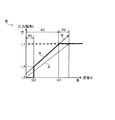
- FIG. 2 is a diagram schematically showing map data M of pressure loss according to the first embodiment.
- a setting A indicated by a bold line indicates a setting example of the map data M of the present embodiment.
- a setting A ′ indicated by a broken line indicates a setting example when the detection error generated by the air flow sensor 34 is not taken into consideration.
- a setting B indicated by a line thinner than the setting A indicates a modification of the setting A.
- the flow rate range R1 indicates a case where the flow rate Q is equal to or less than the predetermined flow rate Q1, and the operation load of the fuel cell system 100 is small.
- the flow rate range R2 indicates a case where the flow rate Q is greater than the predetermined flow rate Q1, and the operation load of the fuel cell system 100 is large. This is because the flow rate Q and the operation load of the fuel cell system 100 are in a proportional relationship. In other words, the operating load of the fuel cell system 100 is a generated current.
- the controller 5 includes map data M.
- the controller 5 uses the map data M to estimate the pressure loss L based on the flow rate Q.
- the pressure loss L is preset according to the flow rate Q.
- the pressure loss L increases as the flow rate Q increases.
- the map data M is set so that the pressure loss L increases as the flow rate Q is equal to or lower than the predetermined flow rate Q1, that is, as the flow rate Q increases in the flow rate range R1.
- the predetermined flow rate Q1 is the flow rate Q when the pressure loss L is a predetermined value L1 in the flow rate range R1. That is, the predetermined flow rate Q1 is a flow rate set in correspondence with the predetermined value L1.
- the predetermined value L1 is a design maximum value, that is, a maximum value of the pressure loss L that may occur in the design.
- the predetermined value L1 is a constant value.
- the predetermined flow rate Q1 and the predetermined value L1 can be set in advance based on experiments or the like.
- the controller 5 assumes that the pressure loss L is the predetermined value L1 when the flow rate Q is larger than the predetermined flow rate Q1.
- Controller 5 estimates pressure loss L based on the output of air flow sensor 34 as flow rate Q. However, a detection error occurs in the air flow sensor 34. For this reason, when the pressure loss L is estimated based on the output of the air flow sensor 34, if the pressure loss L is estimated based on the setting A ′ that does not consider the detection error generated in the air flow sensor 34, the detection error generated in the air flow sensor 34 is reduced. The pressure loss L is estimated to be different by the amount.
- the pressure loss L is further set to a value that takes into account the detection error generated by the airflow sensor 34. Specifically, the pressure loss L is set so as to increase by the amount corresponding to the detection error generated by the airflow sensor 34.
- the detection error is indicated in the form of ⁇ several percent, for example.
- a detection error on the minus side generated by the airflow sensor 34 and having the maximum magnitude can be used.
- the detection error may be a value that further considers individual sensor differences.
- the predetermined flow rate Q1 is the flow rate Q when the pressure loss L is set to the predetermined value L1 in the flow range R1 in the setting A in consideration of the detection error generated in the air flow sensor 34 in this way.
- the controller 5 can be configured to set the pressure loss L to the predetermined value L1 when it is determined that the pressure loss L is larger than the predetermined value L1 based on the estimated pressure loss L. Also in this case, the controller 5 sets the pressure loss L to the predetermined value L1 when the flow rate Q is larger than the predetermined flow rate Q1. The controller 5 can determine whether or not the estimated pressure loss L is greater than the predetermined value L1.
- the predetermined flow rate Q1 is set to a predetermined value at the setting A ′ shown in FIG. It may be the flow rate Q when estimating L1.
- step S1 the controller 5 detects the flow rate Q of the cathode gas.
- the flow rate Q can be detected based on the output of the air flow sensor 34.
- step S2 the controller 5 estimates the pressure loss L. Specifically, the controller 5 estimates the pressure loss L by referring to the map data M and acquiring the pressure loss L corresponding to the detected flow rate Q.
- step S3 the controller 5 detects the cathode supply pressure.
- the cathode supply pressure can be detected based on the output of the pressure sensor 41.
- step S4 the controller 5 estimates the cathode inlet pressure, which is the pressure of the cathode gas at the cathode electrode side inlet 13, based on the pressure loss L estimated in step S2 and the cathode supply pressure detected in step S3. Specifically, the controller 5 estimates the cathode inlet pressure by subtracting the pressure corresponding to the pressure loss L estimated in Step S2 from the cathode supply pressure detected in Step S3.
- step S5 the controller 5 calculates an anode upper limit pressure that is an upper limit pressure of the anode gas. Specifically, the controller 5 calculates an anode upper limit pressure by adding a pressure corresponding to a predetermined differential pressure described later to the cathode inlet pressure estimated in step S4. After step S5, the process of this flowchart ends.
- the differential pressure between the anode inlet pressure and the cathode inlet pressure lower than the anode inlet pressure needs to be within a predetermined differential pressure.
- the cathode gas humidified by the humidifier 36 flows through the cathode gas supply passage 31 between the humidifier 36 and the cathode electrode side inlet 13. For this reason, if the cathode inlet pressure is directly detected by the pressure sensor, moisture may adhere and freeze in a low temperature environment.
- the cathode inlet pressure can be estimated based on the cathode supply pressure and the pressure loss L.
- the pressure loss L can be estimated based on the flow rate Q detected by the airflow sensor 34.
- the detection error increases as the flow rate Q to be detected increases. Therefore, the pressure loss L can be estimated to be larger than necessary. As a result, the pressure loss L can be estimated to be a value exceeding the design maximum value.
- the fuel cell system 100 includes a fuel cell stack 1, a compressor 35, an air flow sensor 34, a humidifier 36, and a controller that estimates a pressure loss L based on a flow rate Q detected by the air flow sensor 34. 5 is provided.
- the controller 5 sets the pressure loss L to the predetermined value L1 when the flow rate Q detected by the airflow sensor 34 is larger than the predetermined flow rate Q1.
- the pressure loss L can be set to the predetermined value L1 from the viewpoint of enhancing robustness against sensor error and sensor failure, and from avoiding complication of calculation.
- the pressure loss L is estimated to be larger than necessary.
- the pressure loss L can be estimated based on the flow rate Q detected by the airflow sensor 34 as shown by setting B in the flow rate range R2 shown in FIG. However, in this case, as a result of estimating the pressure loss L in consideration of the detection error in advance, the pressure loss L is estimated to be larger than necessary.
- the pressure loss L is set to the predetermined value L1, so that the pressure loss L becomes the design maximum value. None exceed.
- the pressure loss L can be estimated as a smaller value than these cases. As a result, compared to these cases, it is possible to prevent the pressure loss L from being estimated to be larger than necessary.
- the controller 5 may set the pressure loss L to the predetermined value L1 when it is determined that the pressure loss L is larger than the predetermined value L1 based on the estimated pressure loss L. Further, when it is determined that the flow rate is larger than the predetermined flow rate Q1 based on the flow rate Q detected by the air flow sensor 34, the pressure loss L may be set to the predetermined value L1. Also in these cases, it is possible to prevent the pressure loss L from being estimated to be larger than necessary.
- the compressor 35 supplies the cathode gas to the fuel cell stack 1
- the humidifier 36 causes a pressure loss in the cathode gas
- the pressure sensor 41 detects the cathode supply pressure. Then, the controller 5 estimates the cathode inlet pressure based on the cathode supply pressure detected by the pressure sensor 41 and the estimated pressure loss L.
- FIG. 4 is a diagram showing the relationship between the differential pressure between the anode inlet pressure and the cathode inlet pressure and the generated current.
- A shows the change in the generated current and the differential pressure between the anode inlet pressure and the cathode inlet pressure according to the operation time of the fuel cell system 100.
- B shows the change of the anode inlet pressure and the cathode inlet pressure according to the operation time of the fuel cell system 100.
- the generated water that inhibits power generation at the anode electrode can be easily discharged by generating pulsation in the anode gas supplied to the fuel cell stack 1. Therefore, the anode inlet pressure fluctuates as shown in FIG. 4 so as to generate pulsation.
- the anode inlet pressure is set larger than the cathode inlet pressure.
- the generated water that inhibits power generation at the anode electrode can be easily discharged by further increasing the flow rate of the anode gas.
- the generated current is small, that is, when the operation load of the fuel cell system 100 is low, the cathode inlet pressure is also low.
- the fluctuating pressure on the high pressure side of the anode inlet pressure is set lower than when the generated current is large. Accordingly, the drainage performance is also reduced by the amount that the fluctuating pressure is set low. Furthermore, the consumption of anode gas decreases as the operating load of the fuel cell system 100 is lower. Therefore, when the operation load is low, the amount of anode gas supplied is reduced and the drainage performance is also reduced.
- the tank 21 supplies the anode gas to the fuel cell stack 1.
- the controller 5 calculates the anode upper limit pressure which the tank 21 supplies based on the estimated cathode inlet pressure. Specifically, the anode upper limit pressure is calculated by adding a predetermined differential pressure to the estimated cathode inlet pressure.
- the cathode inlet pressure estimated to be smaller than necessary is not used for calculating the anode upper limit pressure. Therefore, in order to ensure a predetermined differential pressure, the anode upper limit pressure is not limited to be smaller than necessary. For this reason, according to the fuel cell system 100 of the said structure, drainage property can be improved.
- the pressure loss L is estimated based on the flow rate Q of the cathode gas that is proportional to the operation load of the fuel cell system 100. For this reason, as the operating load is lower, the cathode inlet pressure can be estimated higher as the pressure loss L becomes smaller. Therefore, the anode upper limit pressure can be calculated higher as the operating load is lower.
- FIG. 5 shows the pressure fluctuation width W of the anode gas according to the target generated current.
- Curve C1 represents the anode upper limit pressure
- curve C2 represents the anode lower limit pressure, which is the lower limit pressure of the anode gas.
- the pressure fluctuation width W can be increased when the target generated current is low, that is, when the operating load is low. As a result, drainage can be ensured when the operation load is low.
- the fuel cell system 100 includes a humidifier bypass passage 37 and a humidifier bypass valve 38. Then, the controller 5 considers the flow rate of the cathode gas flowing through the humidifier bypass passage 37 to be zero regardless of the flow rate adjustment state of the humidifier bypass valve 38, that is, the opening degree of the humidifier bypass valve 38, and reduces the pressure loss L. presume.
- a sensor for detecting the flow rate of the cathode gas flowing through the humidifier bypass passage 37 can be eliminated.
- the robustness against sensor error and sensor failure can be increased by reducing the number of sensors used.
- the pressure loss L is estimated by assuming that all of the flow rate Q of the cathode gas detected by the air flow sensor 34 flows to the humidifier 36. As a result, the pressure loss L is estimated to be larger than actual. Therefore, the cathode inlet pressure is estimated to be lower than actual.
- the cathode inlet pressure is estimated to be lower than the actual pressure, it is determined that the differential pressure becomes the predetermined differential pressure while the actual cathode inlet pressure is within the predetermined differential pressure range. For this reason, it can be determined that the differential pressure becomes the predetermined differential pressure earlier before the differential pressure actually becomes the predetermined differential pressure. Therefore, the differential pressure can be secured safely as much as it can be determined strictly whether the differential pressure is within the predetermined differential pressure.
- the controller 5 largely estimates the pressure loss L by an amount corresponding to the minus-side detection error generated by the airflow sensor 34.
- the fuel cell system 100 having such a configuration, it is possible to prevent the pressure loss L from being estimated to be smaller than actual due to the detection error of the air flow sensor 34. Therefore, it is possible to prevent the cathode inlet pressure from being estimated to be higher than the actual pressure, so that the differential pressure can be secured safely.
- the air flow sensor 34 can obtain a mass flow rate, whereas the pressure loss L is strictly determined by a volume flow rate. That is, the pressure loss L is affected by the pressure and temperature of the cathode gas in addition to the mass flow rate.
- the pressure loss L it is preferable to set the pressure loss L to a value that further considers the pressure and temperature of the cathode gas.
- the pressure and temperature of the cathode gas are, for example, the pressure and temperature of the cathode gas at the outlet of the compressor 35.
- the pressure and temperature of the cathode gas the pressure and temperature of the cathode gas that constitutes the condition that the pressure loss L is maximized can be applied.
- the influence of the pressure and temperature of the cathode gas is based on the output of a sensor that detects the pressure of the cathode gas such as the pressure sensor 41 and the output of the sensor that detects the temperature of the cathode gas. You may correct
- the controller 5 further sets the pressure loss L to a predetermined value L2 when the flow rate Q of the cathode gas detected by the airflow sensor 34 is smaller than the predetermined flow rate Q2.
- the map data M is set as described below. Except for these points, the fuel cell system 100 of the present embodiment is configured in the same manner as the fuel cell system 100 of the first embodiment.
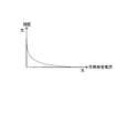
- FIG. 6 is a diagram schematically showing map data M of pressure loss according to the second embodiment.
- the flow rate range R3 is a range in which the flow rate Q is smaller than the predetermined flow rate Q2 and the pressure loss L does not occur or a very small pressure loss L is generated. For this reason, the flow rate range R3 includes the case where the flow rate Q is zero. The flow range R3 is included in the flow range R1.
- the pressure loss L is set to be a predetermined value L2.
- the predetermined flow rate Q2 is set to a value smaller than the predetermined flow rate Q1.
- the predetermined flow rate Q2 is a flow rate for setting the flow rate range R3.
- the predetermined value L2 is a pressure loss L set in correspondence with the flow rate range R3.
- the predetermined value L2 is a constant value, specifically zero.
- the predetermined value L2 may be a pressure loss L generated at a very small flow rate.
- the predetermined value L2 can be a value smaller than the pressure loss L estimated based on at least the setting B.
- the predetermined value L3 is a pressure loss L set in correspondence with the predetermined flow rate Q2.
- the predetermined flow rate Q2, the predetermined value L2, and the predetermined value L3 can be set in advance based on experiments or the like.
- the controller 5 refers to the map data M created as described above on the basis of the flow rate Q of the cathode gas detected by the air flow sensor 34, and if the flow rate Q is smaller than the predetermined flow rate Q2, the pressure loss L is reduced.
- the predetermined value L2 is the predetermined value of the cathode gas detected by the air flow sensor 34.
- the pressure loss L when the pressure loss L is set to a value that considers the error of the air flow sensor 34, the pressure loss L can be estimated to be larger than necessary when the flow rate Q is very small. There is sex.
- the controller 5 sets the pressure loss L to a predetermined value L2 when the flow rate Q is smaller than the predetermined flow rate Q2. According to the fuel cell system 100 having such a configuration, it is possible to prevent the pressure loss L from being estimated to be larger than necessary even when the flow rate Q is very small.
- the controller 5 may set the pressure loss L to the predetermined value L2 when it is determined that the pressure loss L is smaller than the predetermined value L3 based on the estimated pressure loss L. Further, when it is determined that the flow rate is equal to or less than the predetermined flow rate Q2 based on the flow rate Q detected by the airflow sensor 34, the pressure loss L may be set to the predetermined value L2. Also in these cases, it is possible to prevent the pressure loss L from being estimated to be larger than necessary when the flow rate Q is very small.
- the controller 5 estimates a humidifier bypass flow rate that is a flow rate of the cathode gas flowing through the humidifier bypass passage 37.
- the pressure loss L is estimated based on the humidifier bypass flow rate of the cathode gas thus estimated.
- the fuel cell system 100 of the present embodiment is configured in the same manner as the fuel cell system 100 of the first embodiment. Similar changes may be applied to the fuel cell system 100 of the second embodiment.
- the humidifier bypass flow rate changes according to the flow rate of the fluid supplied by the compressor 35 and the opening degree of the humidifier bypass valve 38. For this reason, the controller 5 specifically estimates the humidifier bypass flow rate based on the flow rate of the fluid supplied by the compressor 35 and the opening degree of the humidifier bypass valve 38.
- FIG. 7 is a view showing an example of setting the opening of the humidifier bypass valve 38.
- FIG. 8 is a diagram illustrating a flow coefficient setting example of the humidifier bypass passage 37.
- the opening degree of the humidifier bypass valve 38 is set according to the target generated current. Specifically, it is set to be smaller as the target generated current is larger.
- the flow coefficient of the humidifier bypass passage 37 is set to increase as the opening degree of the humidifier bypass valve 38 increases.
- the controller 5 has map data in which the relationships shown in FIGS. 7 and 8 are set in advance, so that the opening degree of the humidifier bypass valve 38 and the flow coefficient of the humidifier bypass passage 37 are grasped based on the target generated current. can do.
- the humidifier bypass flow rate can be estimated based on the grasped flow coefficient and the flow rate of the fluid supplied by the compressor 35.
- the controller 5 may estimate the humidifier bypass flow rate based on a target generated current that is an example of a parameter having a correlation with the opening degree of the humidifier bypass valve 38 instead of the opening degree of the humidifier bypass valve 38. .
- the humidifier 36 is a main element that generates the pressure loss L in the fuel cell system 100.
- the flow rate of the cathode gas flowing through the humidifier 36 decreases by the amount of the cathode gas flowing through the humidifier bypass passage 37.
- the controller 5 calculates a flow rate obtained by subtracting the humidifier bypass flow rate from the flow rate Q based on the flow rate Q and the estimated humidifier bypass flow rate. Then, the pressure loss L is estimated based on the flow rate calculated instead of the flow rate Q.
- the controller 5 estimates the flow rate of the cathode gas flowing through the humidifier bypass passage 37. Further, the pressure loss L is estimated based on the flow rate Q and the estimated humidifier bypass flow rate.
- the pressure loss L can be estimated more accurately by taking into consideration the influence of the flow rate of the cathode gas flowing through the humidifier bypass passage 37.
- the pressure loss L can be estimated to be small by an amount corresponding to the flow rate of the cathode gas flowing through the humidifier bypass passage 37. Accordingly, the cathode inlet pressure can be estimated to be high by the amount of estimation of the pressure loss L being small.
- the anode upper limit pressure can be calculated to be higher as the cathode inlet pressure is estimated to be higher.
- the humidifier bypass flow rate is estimated, so that a sensor for detecting the humidifier bypass flow rate can be eliminated.
- the robustness against sensor error and sensor failure can be increased by reducing the number of sensors used.
- the controller 5 changes the predetermined value L ⁇ b> 1 based on the characteristic change of the pressure loss generated in the humidifier 36. Except for this point, the fuel cell system 100 of the present embodiment is configured similarly to the fuel cell system 100 of the first embodiment. Similar changes may be applied to the fuel cell system 100 of the second embodiment or the third embodiment.
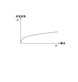
- FIG. 9 is a diagram showing a change in characteristics of the pressure loss generated in the humidifier 36.
- produces in the humidifier 36 is shown.
- the pressure loss characteristic change corresponding to the total operation time of the fuel cell system 100 that is, the pressure loss change with time, is shown as the pressure loss characteristic change.
- the maximum value MAX is a value corresponding to the predetermined value L1
- the minimum value MIN is a value corresponding to the predetermined value L2.
- the characteristic change that the pressure loss decreases as the total operation time of the fuel cell system 100 becomes longer can be obtained in advance based on an experiment or the like.
- the characteristic change of the pressure loss generated in the humidifier 36 may be a characteristic change that increases the pressure loss as the total operation time of the fuel cell system 100 becomes longer.
- the controller 5 changes the predetermined value L1 based on a change in characteristics of the pressure loss generated in the humidifier 36.
- the fuel cell system 100 having the above configuration, even when the pressure loss characteristic change occurs in the humidifier 36, it is possible to estimate the pressure loss L more accurately considering this effect. Thereby, the cathode inlet pressure can be estimated more accurately, and the anode upper limit pressure can be calculated more accurately.
- the controller 5 may be configured to change at least one of the predetermined value L1 and the predetermined value L2 based on a characteristic change of the pressure loss generated in the humidifier 36. In this case, by changing the predetermined value L2, when the flow rate Q is very small, it is possible to prevent the pressure loss L from being estimated to be larger than necessary, for example, by an amount corresponding to a change in pressure loss characteristics.
- the fluid in which the pressure loss occurs is the cathode gas
- the fluid in which the pressure loss occurs may be anode gas or the coolant of the fuel cell system 100.
- the configuration that causes the pressure loss in the fluid may be a configuration other than the humidifier 36.
- the anode gas supply / discharge device 2 is a dead-end type device that supplies the anode off gas to the fuel cell stack 1 in a reverse flow.
- the anode gas supply / discharge device 2 may be configured as a circulation type device that recirculates the anode off gas to the fuel cell stack 1 via the anode gas supply passage 22.
- the pressure loss L may be estimated using a model expression of the pressure loss L that defines the pressure loss L based on the flow rate Q.
- the controller 5 estimates the pressure loss L using the humidifier bypass passage 37 as a bypass passage that bypasses the humidifier 36 has been described.
- the controller 5 may estimate the pressure loss L using the system bypass passage 39 as a bypass passage that bypasses the humidifier 36.
- the controller 5 may estimate the pressure loss L by regarding the flow rate of the cathode gas flowing through the system bypass passage 39 as zero regardless of the flow rate adjustment state of the system bypass valve 40. Further, the flow rate of the cathode gas flowing through the system bypass passage 39 may be estimated, and the pressure loss L may be estimated based on the flow rate thus estimated in addition to the flow rate Q.
- the same setting as the opening setting of the humidifier bypass valve 38 shown in FIG. 7 can be applied to the opening degree of the system bypass valve 40.
- the same setting as the flow coefficient setting of the humidifier bypass passage 37 shown in FIG. 8 can be applied to the flow coefficient of the system bypass passage 39.
- the controller 5 may estimate the pressure loss L using the humidifier bypass passage 37 and the system bypass passage 39 as bypass passages that bypass the humidifier 36.
- controller 5 implements functional units such as the pressure loss estimation unit, the pressure estimation unit, the calculation unit, the change unit, and the bypass flow rate estimation unit.
- functional units such as a pressure loss estimation unit, a pressure estimation unit, a calculation unit, a change unit, and a bypass flow rate estimation unit may be realized by a plurality of controllers.
Landscapes
- Life Sciences & Earth Sciences (AREA)
- Engineering & Computer Science (AREA)
- Manufacturing & Machinery (AREA)
- Sustainable Development (AREA)
- Sustainable Energy (AREA)
- Chemical & Material Sciences (AREA)
- Chemical Kinetics & Catalysis (AREA)
- Electrochemistry (AREA)
- General Chemical & Material Sciences (AREA)
- Fuel Cell (AREA)
Abstract
燃料電池システムは、燃料電池スタックと、燃料電池スタックにカソードガスを供給するコンプレッサと、コンプレッサが供給するカソードガスの流量を検出するエアフローセンサと、コンプレッサ及び燃料電池スタック間のカソードガス供給通路に設けられた加湿器と、エアフローセンサが検出する流量に基づき、コンプレッサ及び燃料電池スタック間で発生するカソードガスの圧力損失を推定するコントローラと、を備える。コントローラは、流量が所定流量より大きい場合に、圧力損失を所定値とする。
Description
本発明は燃料電池システム及び燃料電池システムの圧力損失推定方法に関する。
JP2008-77955Aには、燃料電池スタックよりも下流側の空気オフガスの圧力を検出する出口側ガス検出用圧力センサの異常を判定する技術が開示されている。この技術では、エアコンプレッサの吐出側で燃料電池スタックよりも上流側の空気の圧力を検出し、検出した圧力からシステム内部圧力損失を減じた値を用いて、出口側ガス検出用圧力センサの異常を判定する。システム内部圧力損失は、エアコンプレッサのガス吐出流量に基づき推定される。
燃料電池入口の圧力は、燃料電池に流体を供給する供給部出口の圧力と、当該供給部及び燃料電池間で発生する流体の圧力損失と、に基づき推定することができる。圧力損失は、燃料電池に供給する流体の流量に基づき推定することができる。
ところが、一般に流量検出センサは、検出する流体の流量が大きい場合ほど、検出誤差が大きくなる。このため、流体の流量が大きい場合ほど、圧力損失は実際より必要以上に大きく推定される虞がある。
本発明は上記に鑑みてなされてものであり、圧力損失が実際より必要以上に大きく推定されることを防止可能な燃料電池システム及び燃料電池システムの圧力損失推定方法を提供することを目的とする。
本発明のある態様の燃料電池システムは、燃料電池と、前記燃料電池に流体を供給する供給部と、前記供給部が供給する流体の流量を検出する流量検出部と、前記供給部及び前記燃料電池間の流体供給通路に設けられ、前記供給部が供給する流体に圧力損失を生じさせる圧力損失部と、前記流量検出部が検出する流体の流量に基づき、前記供給部及び前記燃料電池間で発生する流体の圧力損失を推定する圧力損失推定部と、を備える。そして、前記圧力損失推定部は、前記流量検出部が検出する流体の流量が所定流量より大きい場合に、前記供給部及び前記燃料電池間で発生する流体の圧力損失を所定値とする。
以下、添付図面を参照しながら本発明の実施形態について説明する。いくつかの図面を通して付された同じ符号は、同一又は対応する構成を示す。
(第1実施形態)
燃料電池は燃料極であるアノード電極と、酸化剤極であるカソード電極とによって電解質膜を挟み込んだ構造を有する。燃料電池は、燃料ガスとして水素を含有するアノードガスをアノード電極に、酸化剤ガスとして酸素を含有するカソードガスをカソード電極にそれぞれ供給することによって発電する。アノード電極及びカソード電極の両電極において進行する電極反応は以下の通りである。
燃料電池は燃料極であるアノード電極と、酸化剤極であるカソード電極とによって電解質膜を挟み込んだ構造を有する。燃料電池は、燃料ガスとして水素を含有するアノードガスをアノード電極に、酸化剤ガスとして酸素を含有するカソードガスをカソード電極にそれぞれ供給することによって発電する。アノード電極及びカソード電極の両電極において進行する電極反応は以下の通りである。
アノード電極 : 2H2 →4H+ +4e- …(1)
カソード電極 : 4H+ +4e- +O2 →2H2O …(2)
この(1)(2)の電極反応によって燃料電池は1ボルト程度の起電力を生じる。
カソード電極 : 4H+ +4e- +O2 →2H2O …(2)
この(1)(2)の電極反応によって燃料電池は1ボルト程度の起電力を生じる。
このような燃料電池を自動車用動力源として使用する場合には、要求される電力が大きい。このためこの場合には、数百枚の燃料電池を積層した燃料電池スタックとして燃料電池を使用する。そして、燃料電池スタックにアノードガス及びカソードガスを供給する燃料電池システムを構成して、車両駆動用の電力を取り出す。
図1は、燃料電池システム100の概略構成図である。
燃料電池システム100は、燃料電池スタック1と、アノードガス給排装置2と、カソードガス給排装置3と、コントローラ5と、を備える。
燃料電池スタック1は、複数枚の燃料電池を積層した積層電池であり、アノードガス及びカソードガスの供給を受けて発電する。そして、発電した電力を車両駆動用モータなど各種の電装部品に供給する。
アノードガス給排装置2は、タンク21と、アノードガス供給通路22と、調圧弁23と、アノードガス排出通路24と、排出弁25と、圧力センサ26と、を備える。
タンク21は、アノードガスを高圧状態に保って貯蔵する。タンク21は、燃料電池スタック1にアノードガスを供給する。
アノードガス供給通路22は、燃料電池スタック1に供給するアノードガスが流れる通路である。アノードガス供給通路22は、その一端がタンク21に接続され、その他端が燃料電池スタック1のアノード極側入口11に接続される。
調圧弁23は、アノードガス供給通路22に設けられる。調圧弁23は、タンク21からアノードガス供給通路22に流れ出したアノードガスの圧力を所望の圧力に調節する。
アノードガス排出通路24は、燃料電池スタック1から排出されたアノードオフガスが流れる通路である。アノードガス排出通路24は、その一端が燃料電池スタック1のアノード極側出口12に接続され、その他端がカソードガス給排装置3のカソードガス排出通路32に接続される。
アノードオフガスは、電極反応で使用されなかった余剰のアノードガスと、カソード側からリークしてきた窒素などの不活性ガスとの混合ガスである。アノードオフガスは、発電過程で生じる水分を含む。
排出弁25は、アノードガス排出通路24に設けられる。排出弁25は、アノードガス排出通路24におけるアノードオフガスや凝縮水の流通の制限及び制限の解除を行う。流通を制限することは、流通を禁止することを含む。
圧力センサ26は、アノードガス供給通路22に設けられる。圧力センサ26は、アノードガス供給通路22のうち調圧弁23及び燃料電池スタック1間の部分に設けられる。圧力センサ26は、アノード極側入口11の圧力であるアノード入口圧を検出する。
カソードガス給排装置3は、カソードガス供給通路31と、カソードガス排出通路32と、フィルタ33と、エアフローセンサ34と、コンプレッサ35と、加湿器36と、を備える。また、加湿器バイパス通路37と、加湿器バイパス弁38と、システムバイパス通路39と、システムバイパス弁40と、圧力センサ41と、を備える。
カソードガス供給通路31は、燃料電池スタック1に供給するカソードガスが流れる通路である。カソードガス供給通路31は、その一端がフィルタ33に接続され、その他端が燃料電池スタック1のカソード極側入口13に接続される。
カソードガス排出通路32は、燃料電池スタック1から排出されるカソードオフガスが流れる通路である。カソードガス排出通路32は、その一端が燃料電池スタック1のカソード極側出口14に接続され、その他端が開口端となっている。カソードオフガスは、カソードガスと、電極反応によって生じた水蒸気との混合ガスである。
フィルタ33、エアフローセンサ34及びコンプレッサ35は、カソードガス供給通路31に設けられる。フィルタ33は、カソードガスに含まれる異物を除去する。カソードガスは具体的には、空気である。エアフローセンサ34は、カソードガス供給通路31のうちコンプレッサ35より上流の部分に設けられる。エアフローセンサ34は、コンプレッサ35が供給するカソードガスの流量Qを検出する。コンプレッサ35は、燃料電池スタック1にカソードガスを供給する。
加湿器36は、カソードガス供給通路31及びカソードガス排出通路32に設けられる。加湿器36は、カソードガス供給通路31においてコンプレッサ35及び燃料電池スタック1間に設けられる。加湿器36は、カソードガスを加湿する。加湿器36は具体的には、カソードオフガスに含まれる水分を回収し、回収した水分でカソードガスを加湿する。加湿器36は、カソードガスに圧力損失を生じさせる。
加湿器バイパス通路37は、カソードガス供給通路31のうち加湿器36の上流及び下流の部分を接続する。
加湿器バイパス弁38は、加湿器バイパス通路37に設けられる。加湿器バイパス弁38は、加湿器バイパス通路37を流通するカソードガスの流量を調整する。加湿器バイパス弁38はカソードガスの流量を調整することで、燃料電池スタック1に供給されるカソードガスの湿度を調整する。
システムバイパス通路39は、カソードガス供給通路31のうち加湿器36より上流の部分、及びカソードガス排出通路32のうち加湿器36より下流の部分を接続する。システムバイパス通路39は具体的には、カソードガス供給通路31のうち加湿器バイパス通路37が接続する部分より上流、且つコンプレッサ35より下流の部分に接続される。また、カソードガス排出通路32のうち加湿器36より下流、且つアノードガス排出通路24が接続する部分より上流の部分に接続される。システムバイパス通路39は、カソードガス供給通路31から加湿器36及び燃料電池スタック1を迂回してカソードガス排出通路32にカソードガスを流通させる。
システムバイパス弁40は、システムバイパス通路39に設けられる。システムバイパス弁40は、システムバイパス通路39を流通するカソードガスの流量を調整する。
圧力センサ41は、カソードガス供給通路31に設けられる。圧力センサ41は具体的には、カソードガス供給通路31のうちコンプレッサ35及び加湿器36間の部分に設けられる。当該部分はさらに具体的には、システムバイパス通路39が接続する部分より上流の部分となっている。圧力センサ41は、コンプレッサ35出口のカソードガスの圧力であるカソード供給圧を検出する。
コントローラ5は電子制御装置であり、マイクロコンピュータで構成される。コントローラ5には、圧力センサ26や、エアフローセンサ34や、圧力センサ41からの信号が入力される。コントローラ5は、調圧弁23や、排出弁25や、コンプレッサ35や、加湿器バイパス弁38や、システムバイパス弁40を制御する。また、圧力損失Lの推定を行う。
圧力損失Lは、コンプレッサ35及び燃料電池スタック1間で発生するカソードガスの圧力損失である。圧力損失Lは、加湿器36で発生するカソードガスの圧力損失を含む。圧力損失Lは、加湿器36で発生するカソードガスの圧力損失であってもよい。つまり、カソードガス供給通路31が生じさせる圧力損失を無視した圧力損失であってもよい。
図2は第1実施形態の圧力損失のマップデータMを模式的に示す図である。太線で示す設定Aは、本実施形態のマップデータMの設定例を示す。破線で示す設定A´は、エアフローセンサ34で発生する検出誤差を考慮しない場合の設定例を示す。設定Aより細い線で示す設定Bは、設定Aの変形例を示す。
流量範囲R1は、流量Qが所定流量Q1以下の場合であり、燃料電池システム100の運転負荷が小さい場合を示す。流量範囲R2は、流量Qが所定流量Q1より大きい場合であり、燃料電池システム100の運転負荷が大きい場合を示す。これは、流量Qと燃料電池システム100の運転負荷とが比例関係にあるためである。燃料電池システム100の運転負荷は、換言すれば発電電流である。
コントローラ5は、マップデータMを備える。コントローラ5は、マップデータMを利用して、流量Qに基づき圧力損失Lを推定する。マップデータMでは、設定Aに示すように流量Qに応じて圧力損失Lが予め設定されている。
圧力損失Lは、流量Qが大きい場合ほど大きくなる。このため、マップデータMでは、流量Qが所定流量Q1以下の場合に、つまり流量範囲R1において、流量Qが大きい場合ほど圧力損失Lが大きくなるように設定される。
所定流量Q1は、流量範囲R1において、圧力損失Lを所定値L1とするときの流量Qである。すなわち、所定流量Q1は、所定値L1に対応させて設定される流量である。所定値L1は、設計上の最大値、つまり設計上発生し得る圧力損失Lの最大値である。所定値L1は、一定値である。所定流量Q1及び所定値L1は、実験などに基づき予め設定することができる。
マップデータMではさらに、流量Qが所定流量Q1より大きい場合に、つまり流量範囲R2において、圧力損失Lは所定値L1に設定される。このため、コントローラ5は、流量Qが所定流量Q1より大きい場合には、圧力損失Lが所定値L1であるとする。
コントローラ5は、流量Qとしてエアフローセンサ34の出力に基づき、圧力損失Lを推定する。ところが、エアフローセンサ34では検出誤差が発生する。このため、エアフローセンサ34の出力に基づき圧力損失Lを推定する場合、エアフローセンサ34で発生する検出誤差を考慮しない設定A´に基づき圧力損失Lを推定すると、エアフローセンサ34で発生する検出誤差の分だけ、圧力損失Lが異なる値に推定される。
このため、マップデータMでは、設定Aに示すように、圧力損失Lがさらにエアフローセンサ34で発生する検出誤差を考慮した値に設定される。具体的には、エアフローセンサ34で発生する検出誤差に応じた分だけ、圧力損失Lが大きくなるように設定される。検出誤差は、例えば±数%というかたちで示される。検出誤差には、エアフローセンサ34で発生するマイナス側の検出誤差であって、大きさが最大の検出誤差を用いることができる。検出誤差は、さらにセンサ個体差を考慮した値とされてもよい。
所定流量Q1は具体的には、このようにエアフローセンサ34で発生する検出誤差を考慮した設定Aにおいて、流量範囲R1で圧力損失Lを所定値L1とするときの流量Qとされる。
マップデータMでは、流量Qが所定流量Q1より大きい場合でも、設定Bに示すように、流量Qが大きい場合ほど圧力損失Lが大きくなるように設定されてもよい。
この場合、コントローラ5は、推定した圧力損失Lに基づき、当該圧力損失Lが所定値L1より大きいと判定される場合に、圧力損失Lを所定値L1とするように構成することができる。この場合も、コントローラ5は、流量Qが所定流量Q1より大きい場合に圧力損失Lを所定値L1とすることになる。推定した圧力損失Lが所定値L1より大きいか否かは、コントローラ5で判定することができる。
所定流量Q1は、エアフローセンサ34で発生する検出誤差を考慮せずに、流量Qに応じて圧力損失Lを設定した場合において、つまり、図2に示す設定A´において、圧力損失Lを所定値L1と推定するときの流量Qであってもよい。
次にコントローラ5が行う制御の一例を図3に示すフローチャートを用いて説明する。ステップS1で、コントローラ5はカソードガスの流量Qを検出する。流量Qは、エアフローセンサ34の出力に基づき検出することができる。
ステップS2で、コントローラ5は、圧力損失Lを推定する。コントローラ5は具体的には、マップデータMを参照し、検出した流量Qに対応する圧力損失Lを取得することで、圧力損失Lを推定する。
ステップS3で、コントローラ5はカソード供給圧を検出する。カソード供給圧は、圧力センサ41の出力に基づき検出できる。
ステップS4で、コントローラ5は、ステップS2で推定した圧力損失Lと、ステップS3で検出したカソード供給圧とに基づき、カソード極側入口13のカソードガスの圧力であるカソード入口圧を推定する。コントローラ5は具体的には、ステップS3で検出したカソード供給圧からステップS2で推定した圧力損失L分の圧力を減算することで、カソード入口圧を推定する。
ステップS5で、コントローラ5はアノードガスの上限圧であるアノード上限圧を算出する。コントローラ5は具体的には、ステップS4で推定したカソード入口圧に後述する所定差圧分の圧力を加算することで、アノード上限圧を算出する。ステップS5の後には、本フローチャートの処理は終了する。
次に本実施形態の燃料電池システム100の主な作用効果について説明する。ここで、燃料電池システム100では、アノード入口圧と、アノード入口圧よりも低いカソード入口圧との差圧を所定差圧内に収める必要がある。このためには、アノード入口圧とカソード入口圧とを管理する必要がある。
ところが、加湿器36及びカソード極側入口13間のカソードガス供給通路31には、加湿器36で加湿されたカソードガスが流通する。このため、カソード入口圧を圧力センサで直接検出しようとすると、低温環境下で水分が付着し凍結する可能性がある。
このような場合、カソード入口圧を直接検出するのではなく、カソード入口圧を推定するのが有効である。カソード入口圧は、カソード供給圧と、圧力損失Lとに基づき推定することができる。圧力損失Lは、エアフローセンサ34が検出する流量Qに基づき推定することができる。
ところが、エアフローセンサ34では、検出する流量Qが大きい場合ほど、検出誤差が大きくなるので、圧力損失Lが実際より必要以上に大きく推定され得る。結果、圧力損失Lが設計上の最大値を超えた値に推定され得る。
このような事情に鑑み、燃料電池システム100は、燃料電池スタック1と、コンプレッサ35と、エアフローセンサ34と、加湿器36と、エアフローセンサ34が検出する流量Qに基づき圧力損失Lを推定するコントローラ5と、を備える。そして、コントローラ5は、エアフローセンサ34が検出する流量Qが所定流量Q1より大きい場合に、圧力損失Lを所定値L1とする。
上記構成の燃料電池システム100によれば、次に説明するように圧力損失Lが実際より必要以上に大きく推定されることを防止できる。
すなわち、例えば図2に示す流量範囲R1においては、センサ誤差やセンサ故障に対するロバスト性を高める観点や、演算の複雑化を避ける観点から、圧力損失Lを所定値L1とすることもできる。ところがこの場合には、圧力損失Lが実際より必要以上に大きく推定されてしまう。
また、図2に示す流量範囲R2においては、設定Bで示すように、エアフローセンサ34が検出する流量Qに基づき、圧力損失Lを推定することもできる。ところがこの場合には、予め検出誤差を考慮した圧力損失Lを推定する結果、圧力損失Lが実際より必要以上に大きく推定されてしまう。
これらの場合と比較し、上記構成の燃料電池システム100によれば、流量Qが所定流量Q1より大きい場合に、圧力損失Lを所定値L1とするので、圧力損失Lが設計上の最大値を超えることがない。
このため、上記構成の燃料電池システム100によれば、圧力損失Lをこれらの場合よりも小さな値として推定することができる。結果、これらの場合と比較し、圧力損失Lが実際より必要以上に大きく推定されることを防止できる。
コントローラ5は、推定した圧力損失Lに基づき、当該圧力損失Lが所定値L1より大きいと判定される場合に、圧力損失Lを所定値L1としてもよい。また、エアフローセンサ34が検出する流量Qに基づき、当該流量が所定流量Q1より大きいと判定される場合に、圧力損失Lを所定値L1としてもよい。これらの場合にも、圧力損失Lが実際より必要以上に大きく推定されることを防止できる。
燃料電池システム100では、コンプレッサ35が燃料電池スタック1にカソードガスを供給し、加湿器36がカソードガスに圧力損失を生じさせ、圧力センサ41がカソード供給圧を検出する。そして、コントローラ5は、圧力センサ41が検出するカソード供給圧と、推定した圧力損失Lとに基づき、カソード入口圧を推定する。
このような構成の燃料電池システム100によれば、圧力損失Lとして設計上の最大値を超えた値をカソード入口圧の推定に用いることがない。このため、カソード入口圧が実際より必要以上に小さく推定されることを防止できる。
ところで、燃料電池システム100では、燃料電池スタック1の発電過程で生じる水が、アノード電極で発電を阻害する。このため、燃料電池スタック1の発電過程で生じる水を燃料電池スタック1から排出する必要がある。次にこの点について説明する。
図4は、アノード入口圧及びカソード入口圧の差圧と発電電流の関係を示す図である。(a)は、燃料電池システム100の運転時間に応じたアノード入口圧及びカソード入口圧の差圧と発電電流の変化を示す。(b)は、燃料電池システム100の運転時間に応じたアノード入口圧及びカソード入口圧の変化を示す。
アノード電極で発電を阻害する生成水は、燃料電池スタック1に供給するアノードガスに脈動を発生させることで、排出し易くすることができる。このため、アノード入口圧は、脈動を発生させるべく図4に示すように変動する。アノード入口圧はカソード入口圧より大きく設定される。
アノード電極で発電を阻害する生成水は、さらにアノードガスの流速を高めることで、排出し易くすることができる。ところが、燃料電池システム100では、アノード入口圧とカソード入口圧との差圧を所定差圧内に収める必要がある。そして、発電電流が小さい場合、つまり燃料電池システム100の運転負荷が低い場合には、カソード入口圧も低くなる。
このため、発電電流が小さい場合には、発電電流が大きい場合より、アノード入口圧の高圧側の変動圧が低く設定される。したがって、当該変動圧が低く設定される分、排水性も低くなる。さらに、アノードガスの消費量は、燃料電池システム100の運転負荷が低い場合ほど、少なくなる。したがって、運転負荷が低い場合には、アノードガスの供給量も少なくなる分、排水性も低下する。
このような事情に鑑み、燃料電池システム100では、タンク21が燃料電池スタック1にアノードガスを供給する。そして、コントローラ5は、推定したカソード入口圧に基づき、タンク21が供給するアノード上限圧を算出する。具体的には、推定したカソード入口圧に所定差圧を加算することで、アノード上限圧を算出する。
このような構成の燃料電池システム100によれば、実際より必要以上に小さく推定されたカソード入口圧をアノード上限圧の算出に用いることがない。したがって、所定差圧を確保するために、アノード上限圧が必要以上に小さく制限されることもない。このため、上記構成の燃料電池システム100によれば、排水性を高めることができる。
上記構成の燃料電池システム100では、燃料電池システム100の運転負荷と比例関係にあるカソードガスの流量Qに基づき圧力損失Lを推定する。このため、運転負荷が低い場合ほど、圧力損失Lが小さくなる分、カソード入口圧を高く推定することができる。したがって、運転負荷が低い場合ほど、アノード上限圧も高く算出することができる。
図5は目標発電電流に応じたアノードガスの圧力変動幅Wを示す図である。曲線C1はアノード上限圧を、曲線C2はアノードガスの下限圧であるアノード下限圧を示す。図5に示すように、上記構成の燃料電池システム100によれば、目標発電電流が低い場合、すなわち運転負荷が低い場合に、圧力変動幅Wを大きくすることができる。結果、運転負荷が低い場合に、排水性を確保することができる。
燃料電池システム100は、加湿器バイパス通路37と、加湿器バイパス弁38と、を備える。そして、コントローラ5は、加湿器バイパス弁38の流量調整状態、つまり加湿器バイパス弁38の開度に関わらず、加湿器バイパス通路37を流通するカソードガスの流量をゼロとみなして圧力損失Lを推定する。
このような構成の燃料電池システム100によれば、加湿器バイパス通路37を流通するカソードガスの流量を検出するためのセンサを不要化することができる。結果、圧力損失Lを推定するにあたり、使用するセンサの数を低減する分、センサ誤差やセンサ故障に対するロバスト性を高めることができる。
この場合、エアフローセンサ34で検出したカソードガスの流量Qのすべてが加湿器36に流れるとみなして、圧力損失Lを推定することになる。結果、圧力損失Lは実際より大きく推定されることになる。したがって、カソード入口圧は実際より低く推定されることになる。
但し、この場合には、カソード入口圧が実際より低く推定されるので、実際のカソード入口圧が所定差圧の範囲内にある間に、差圧が所定差圧になると判断される。このため、差圧が実際に所定差圧になる前に早めに所定差圧になると判断することができる。したがって、差圧が所定差圧内であるか否かの判断を厳しく行うことができる分、差圧を安全に確保することができる。
燃料電池システム100では、コントローラ5が、エアフローセンサ34で発生するマイナス側の検出誤差に応じた分だけ、圧力損失Lを大きく推定する。
このような構成の燃料電池システム100によれば、エアフローセンサ34の検出誤差によって、圧力損失Lが実際より小さく推定されることを防止することができる。したがって、カソード入口圧が実際より高く推定されることを防止できるので、差圧を安全に確保することができる。
エアフローセンサ34では具体的には、質量流量が得られるのに対し、圧力損失Lは厳密には体積流量で求められる。つまり、圧力損失Lには、質量流量に加えカソードガスの圧力及び温度が影響する。
このため、圧力損失Lを設定する際には、さらにカソードガスの圧力及び温度を考慮した値に圧力損失Lを設定することが好ましい。カソードガスの圧力及び温度は具体的には例えば、コンプレッサ35出口におけるカソードガスの圧力及び温度である。カソードガスの圧力及び温度には、圧力損失Lが最も大きくなる条件を構成するカソードガスの圧力及び温度を適用することができる。
これにより、カソードガスの圧力及び温度によって、圧力損失Lが実際より小さく推定されることを防止することができる。したがって、カソード入口圧が実際より高く推定されることを防止できるので、差圧を安全に確保することができる。
カソードガスの圧力及び温度を考慮するには、圧力センサ41などカソードガスの圧力を検出するセンサの出力、及びカソードガスの温度を検出するセンサの出力に基づき、カソードガスの圧力及び温度の影響が反映されていない圧力損失Lを補正してもよい。
(第2実施形態)
本実施形態では、コントローラ5がさらに、エアフローセンサ34が検出するカソードガスの流量Qが所定流量Q2より小さい場合に、圧力損失Lを所定値L2とする。また、これに関連し、マップデータMが次に説明するように設定される。これらの点を除き、本実施形態の燃料電池システム100は、第1実施形態の燃料電池システム100と同様に構成される。
本実施形態では、コントローラ5がさらに、エアフローセンサ34が検出するカソードガスの流量Qが所定流量Q2より小さい場合に、圧力損失Lを所定値L2とする。また、これに関連し、マップデータMが次に説明するように設定される。これらの点を除き、本実施形態の燃料電池システム100は、第1実施形態の燃料電池システム100と同様に構成される。
図6は第2実施形態の圧力損失のマップデータMを模式的に示す図である。流量範囲R3は、流量Qが所定流量Q2より小さい場合であり、圧力損失Lが発生しないか、或いはごく小さい圧力損失Lを発生させる流量の範囲である。このため、流量範囲R3は、流量Qがゼロの場合を含む。流量範囲R3は、流量範囲R1に含まれる。
本実施形態のマップデータMではさらに、設定Aで示すように、流量Qが所定流量Q2より小さい場合に、つまり流量範囲R3において、圧力損失Lが所定値L2になるように設定される。所定流量Q2は、所定流量Q1より小さい値に設定される。所定流量Q2は、流量範囲R3を設定する流量である。所定値L2は、流量範囲R3に対応させて設定される圧力損失Lである。所定値L2は一定値であり、具体的にはゼロである。所定値L2は、ごく小さい流量で発生する圧力損失Lであってもよい。所定値L2は、少なくとも設定Bに基づき推定される圧力損失Lより小さい値とすることができる。所定値L3は、所定流量Q2に対応させて設定される圧力損失Lである。所定流量Q2、所定値L2及び所定値L3は、実験などに基づき予め設定することができる。
コントローラ5は、エアフローセンサ34が検出するカソードガスの流量Qに基づき、上記のように作成されたマップデータMを参照することで、流量Qが所定流量Q2より小さい場合には、圧力損失Lを所定値L2とする。
次に本実施形態の燃料電池システム100の主な作用効果について説明する。ここで、第1実施形態で説明したように、圧力損失Lをエアフローセンサ34の誤差を考慮した値に設定すると、流量Qがごく小さい場合に、圧力損失Lが必要以上に大きく推定される可能性がある。
このような事情に鑑み、本実施形態の燃料電池システム100では、コントローラ5は、流量Qが所定流量Q2より小さい場合には、圧力損失Lを所定値L2とする。このような構成の燃料電池システム100によれば、流量Qがごく小さい場合でも、圧力損失Lが必要以上に大きく推定されることを防止できる。
コントローラ5は、推定した圧力損失Lに基づき、当該圧力損失Lが所定値L3より小さいと判定される場合に、圧力損失Lを所定値L2としてもよい。また、エアフローセンサ34が検出する流量Qに基づき、当該流量が所定流量Q2以下であると判定される場合に、圧力損失Lを所定値L2としてもよい。これらの場合にも、流量Qがごく小さい場合に、圧力損失Lが必要以上に大きく推定されることを防止できる。
(第3実施形態)
本実施形態では、コントローラ5が、加湿器バイパス通路37を流通するカソードガスの流量である加湿器バイパス流量を推定する。また、流量Qに加えて、さらにこのようにして推定したカソードガスの加湿器バイパス流量に基づき、圧力損失Lを推定する。これらの点を除き、本実施形態の燃料電池システム100は、第1実施形態の燃料電池システム100と同様に構成される。同様の変更は、第2実施形態の燃料電池システム100に適用されてもよい。
本実施形態では、コントローラ5が、加湿器バイパス通路37を流通するカソードガスの流量である加湿器バイパス流量を推定する。また、流量Qに加えて、さらにこのようにして推定したカソードガスの加湿器バイパス流量に基づき、圧力損失Lを推定する。これらの点を除き、本実施形態の燃料電池システム100は、第1実施形態の燃料電池システム100と同様に構成される。同様の変更は、第2実施形態の燃料電池システム100に適用されてもよい。
加湿器バイパス流量は、コンプレッサ35が供給する流体の流量や、加湿器バイパス弁38の開度に応じて変化する。このため、コントローラ5は具体的には、コンプレッサ35が供給する流体の流量や、加湿器バイパス弁38の開度に基づき、加湿器バイパス流量を推定する。
図7は、加湿器バイパス弁38の開度設定例を示す図である。図8は、加湿器バイパス通路37の流量係数設定例を示す図である。図7に示すように、加湿器バイパス弁38の開度は、目標発電電流に応じて設定される。具体的には、目標発電電流が大きい場合ほど小さくなるように設定される。図8に示すように、加湿器バイパス通路37の流量係数は、加湿器バイパス弁38の開度が大きい場合ほど、大きくなるように設定される。
コントローラ5は、図7及び図8に示す関係を予め設定したマップデータを備えることで、目標発電電流に基づき、加湿器バイパス弁38の開度、さらには加湿器バイパス通路37の流量係数を把握することができる。そして、把握した流量係数や、コンプレッサ35が供給する流体の流量に基づき、加湿器バイパス流量を推定することができる。コントローラ5は、加湿器バイパス弁38の開度の代わりに、加湿器バイパス弁38の開度と相関関係を有するパラメータの一例である目標発電電流に基づき、加湿器バイパス流量を推定してもよい。
ところで、加湿器36は、燃料電池システム100において圧力損失Lを発生させる主な要素である。そして、カソードガスが加湿器バイパス通路37を流通する場合、加湿器バイパス通路37を流通するカソードガスの流量分だけ、加湿器36を流通するカソードガスの流量は減少する。
このため、コントローラ5は具体的には、流量Q及び推定した加湿器バイパス流量に基づき、流量Qから当該加湿器バイパス流量を減じた流量を算出する。そして、流量Qの代わりに算出した流量に基づき、圧力損失Lを推定する。
次に本実施形態の燃料電池システム100の主な作用効果について説明する。本実施形態の燃料電池システム100では、コントローラ5が、加湿器バイパス通路37を流通するカソードガスの流量を推定する。また、流量Qと、推定した加湿器バイパス流量とに基づき、圧力損失Lを推定する。
上記構成の燃料電池システム100によれば、加湿器バイパス通路37を流通するカソードガスの流量の影響を加味することで、より正確な圧力損失Lを推定できる。
この場合、加湿器バイパス通路37を流通するカソードガスの流量に応じた分だけ、圧力損失Lを小さく推定することができる。したがって、圧力損失Lを小さく推定する分、カソード入口圧を高く推定することもできる。また、カソード入口圧を高く推定する分、アノード上限圧を高く算出することもできる。
上記構成の燃料電池システム100では、圧力損失Lを推定するにあたり、加湿器バイパス流量を推定するので、加湿器バイパス流量を検出するためのセンサを不要化することもできる。結果、圧力損失Lを推定するにあたり、使用するセンサの数を低減する分、センサ誤差やセンサ故障に対するロバスト性を高めることができる。
(第4実施形態)
本実施形態では、コントローラ5が、加湿器36で発生する圧力損失の特性変化に基づき、所定値L1を変更する。この点を除き、本実施形態の燃料電池システム100は、第1実施形態の燃料電池システム100と同様に構成される。同様の変更は、第2実施形態や第3実施形態の燃料電池システム100に適用されてもよい。
本実施形態では、コントローラ5が、加湿器36で発生する圧力損失の特性変化に基づき、所定値L1を変更する。この点を除き、本実施形態の燃料電池システム100は、第1実施形態の燃料電池システム100と同様に構成される。同様の変更は、第2実施形態や第3実施形態の燃料電池システム100に適用されてもよい。
図9は、加湿器36で発生する圧力損失の特性変化を示す図である。加湿器36で発生する圧力損失の最大値MAX及び最小値MINの特性変化を示す。図9では、圧力損失の特性変化として、燃料電池システム100の総運転時間に応じた圧力損失の特性変化、すなわち圧力損失の経時変化を示す。最大値MAXは、所定値L1相当の値であり、最小値MINは、所定値L2相当の値である。
図9に示すように、加湿器36では、燃料電池システム100の総運転時間が長くなるほど、圧力損失が小さくなる特性変化が発生する。このような特性変化は、実験などに基づき予め求めることができる。加湿器36で発生する圧力損失の特性変化は、燃料電池システム100の総運転時間が長くなるほど、圧力損失が大きくなる特性変化であってもよい。
次に本実施形態の燃料電池システム100の主な作用効果について説明する。本実施形態の燃料電池システム100では、コントローラ5が、加湿器36で発生する圧力損失の特性変化に基づき、所定値L1を変更する。
上記構成の燃料電池システム100によれば、加湿器36で圧力損失の特性変化が発生した場合でも、この影響を加味したより正確な圧力損失Lを推定できる。またこれにより、カソード入口圧をより正確に推定できるとともに、アノード上限圧をより正確に算出することができる。
コントローラ5は、加湿器36で発生する圧力損失の特性変化に基づき、所定値L1及び所定値L2のうち少なくともいずれかを変更するように構成されてもよい。この場合、所定値L2を変更することで、流量Qがごく小さい場合に、例えば圧力損失の特性変化に応じた分だけ、圧力損失Lが必要以上に大きく推定されることを防止できる。
以上、本発明の実施形態について説明したが、上記実施形態は本発明の適用例の一部を示したに過ぎず、本発明の技術的範囲を上記実施形態の具体的構成に限定する趣旨ではない。
上述した実施形態では、圧力損失が発生する流体がカソードガスである場合について説明した。しかしながら、圧力損失が発生する流体は、アノードガスや、燃料電池システム100の冷却液であってもよい。圧力損失を流体に生じさせる構成も、加湿器36以外の構成であってもよい。
上述した実施形態では、アノードガス給排装置2がアノードオフガスを逆流させるようにして燃料電池スタック1に供給するデッドエンド型の装置である場合について説明した。しかしながら、アノードガス給排装置2は、アノードガス供給通路22を介して燃料電池スタック1にアノードオフガスを還流させる循環型の装置として構成されてもよい。
上述した実施形態では、マップデータMを用いて圧力損失Lを推定する場合について説明した。しかしながら、圧力損失Lは、流量Qに基づき圧力損失Lを定義する圧力損失Lのモデル式を用いて推定されてもよい。
上述した実施形態では、コントローラ5が、加湿器バイパス通路37を、加湿器36をバイパスするバイパス通路として圧力損失Lを推定する場合について説明した。しかしながら、コントローラ5は、システムバイパス通路39を、加湿器36をバイパスするバイパス通路として圧力損失Lを推定してもよい。
すなわち、コントローラ5はシステムバイパス弁40の流量調整状態に関わらず、システムバイパス通路39を流通するカソードガスの流量をゼロとみなして圧力損失Lを推定してもよい。また、システムバイパス通路39を流通するカソードガスの流量を推定し、流量Qに加えてさらにこのようにして推定した流量に基づき、圧力損失Lを推定してもよい。
この場合、システムバイパス弁40の開度には、図7に示す加湿器バイパス弁38の開度設定と同様の設定を適用することができる。また、システムバイパス通路39の流量係数には、図8に示す加湿器バイパス通路37の流量係数設定と同様の設定を適用することができる。コントローラ5は、加湿器バイパス通路37及びシステムバイパス通路39それぞれを、加湿器36をバイパスするバイパス通路として圧力損失Lを推定してよい。
上述した実施形態では、圧力損失推定部や圧力推定部や算出部や変更部やバイパス流量推定部などの機能部をコントローラ5で実現する場合について説明した。しかしながら、圧力損失推定部や圧力推定部や算出部や変更部やバイパス流量推定部などの機能部は、複数のコントローラで実現されてもよい。
本願は2014年7月24日に日本国特許庁に出願された特願2014-151263に基づく優先権を主張し、この出願のすべての内容は参照により本明細書に組み込まれる。
Claims (11)
- 燃料電池と、
前記燃料電池に流体を供給する供給部と、
前記供給部が供給する流体の流量を検出する流量検出部と、
前記供給部及び前記燃料電池間の流体供給通路に設けられ、前記供給部が供給する流体に圧力損失を生じさせる圧力損失部と、
前記流量検出部が検出する流体の流量に基づき、前記供給部及び前記燃料電池間で発生する流体の圧力損失を推定する圧力損失推定部と、を備え、
前記圧力損失推定部は、前記流量検出部が検出する流体の流量が所定流量より大きい場合に、前記供給部及び前記燃料電池間で発生する流体の圧力損失を所定値とする、
燃料電池システム。 - 請求項1に記載の燃料電池システムであって、
前記圧力損失推定部は、推定した圧力損失に基づき、当該圧力損失が前記所定値より大きいと判定される場合に、圧力損失を前記所定値とする、
燃料電池システム。 - 請求項1又は2に記載の燃料電池システムであって、
前記所定流量より小さい第2の所定流量と、前記所定値より小さい第2の所定値と、をさらに設定し、
前記圧力損失推定部は、前記流量検出部が検出する流体の流量が前記第2の所定流量より小さい場合に、前記供給部及び前記燃料電池間で発生する流体の圧力損失を前記第2の所定値とする、
燃料電池システム。 - 請求項3に記載の燃料電池システムであって、
前記第2の所定流量に対応させて第3の所定値をさらに設定し、
前記圧力損失推定部は、推定した圧力損失に基づき、当該圧力損失が前記第3の所定値より小さいと判定される場合に、圧力損失を前記第2の所定値とする、
燃料電池システム。 - 請求項1から4いずれか1項に記載の燃料電池システムであって、
前記圧力損失部で発生する圧力損失の特性変化に基づき、前記所定値を変更する変更部、
をさらに備える燃料電池システム。 - 請求項1から5いずれか1項に記載の燃料電池システムであって、
前記圧力損失推定部は、前記流量検出部で発生する検出誤差に応じた分だけ、前記供給部及び前記燃料電池間で発生する流体の圧力損失を大きく推定する、
燃料電池システム。 - 請求項1から6いずれか1項に記載の燃料電池システムであって、
前記供給部が前記燃料電池に供給する流体は、カソードガスであり、
前記圧力損失部は、前記供給部が供給する流体を加湿する加湿器であり、
前記供給部出口のカソードガスの圧力を検出する圧力検出部と、
前記圧力検出部が検出するカソードガスの圧力と、前記圧力損失推定部が推定する圧力損失とに基づき、前記燃料電池入口のカソードガスの圧力を推定する圧力推定部と、
をさらに備える燃料電池システム。 - 請求項7に記載の燃料電池システムであって、
前記燃料電池にアノードガスを供給する第2の供給部と、
前記圧力推定部が推定するカソードガスの圧力に基づき、前記第2の供給部が供給するアノードガスの上限圧を算出する算出部と、
をさらに備える燃料電池システム。 - 請求項7又は8に記載の燃料電池システムであって、
前記加湿器をバイパスするバイパス通路と、
前記バイパス通路を流通するカソードガスの流量を調整する調整部と、
をさらに備え、
前記圧力損失推定部は、前記調整部の流量調整状態に関わらず、前記バイパス通路を流通するカソードガスの流量をゼロとみなして前記供給部及び前記燃料電池間で発生する流体の圧力損失を推定する、
燃料電池システム。 - 請求項7又は8に記載の燃料電池システムであって、
前記加湿器をバイパスするバイパス通路と、
前記バイパス通路を流通するカソードガスの流量を調整する調整部と、
前記バイパス通路を流通するカソードガスの流量を推定するバイパス流量推定部と、
をさらに備え、
前記圧力損失推定部は、前記流量検出部が検出する流体の流量に加えてさらに前記バイパス流量推定部が推定するカソードガスの流量に基づき、前記供給部及び前記燃料電池間で発生する流体の圧力損失を推定する、
燃料電池システム。 - 燃料電池と、前記燃料電池に流体を供給する供給部と、前記供給部が供給する流体の流量を検出する流量検出部と、前記供給部及び前記燃料電池間の流体供給通路に設けられ前記供給部が供給する流体に圧力損失を生じさせる圧力損失部と、を設け、
前記流量検出部が検出する流体の流量に基づき、前記供給部及び前記燃料電池間で発生する流体の圧力損失を推定し、
前記流量検出部が検出する流体の流量が所定流量より大きい場合に、前記供給部及び前記燃料電池間で発生する流体の圧力損失を所定値とする、
燃料電池システムの圧力損失推定方法。
Priority Applications (1)
| Application Number | Priority Date | Filing Date | Title |
|---|---|---|---|
| JP2016535839A JP6428777B2 (ja) | 2014-07-24 | 2015-06-11 | 燃料電池システム及び燃料電池システムの圧力損失推定方法 |
Applications Claiming Priority (2)
| Application Number | Priority Date | Filing Date | Title |
|---|---|---|---|
| JP2014151263 | 2014-07-24 | ||
| JP2014-151263 | 2014-07-24 |
Publications (1)
| Publication Number | Publication Date |
|---|---|
| WO2016013320A1 true WO2016013320A1 (ja) | 2016-01-28 |
Family
ID=55162856
Family Applications (1)
| Application Number | Title | Priority Date | Filing Date |
|---|---|---|---|
| PCT/JP2015/066908 WO2016013320A1 (ja) | 2014-07-24 | 2015-06-11 | 燃料電池システム及び燃料電池システムの圧力損失推定方法 |
Country Status (2)
| Country | Link |
|---|---|
| JP (1) | JP6428777B2 (ja) |
| WO (1) | WO2016013320A1 (ja) |
Cited By (1)
| Publication number | Priority date | Publication date | Assignee | Title |
|---|---|---|---|---|
| CN114520352A (zh) * | 2022-01-10 | 2022-05-20 | 江苏氢导智能装备有限公司 | 气体压力控制装置及电堆测试平台 |
Citations (9)
| Publication number | Priority date | Publication date | Assignee | Title |
|---|---|---|---|---|
| JPH06137914A (ja) * | 1992-10-27 | 1994-05-20 | Yazaki Corp | 流量測定装置 |
| JP2002216815A (ja) * | 2001-01-22 | 2002-08-02 | Honda Motor Co Ltd | 燃料電池用加湿システム |
| JP2002298885A (ja) * | 2001-03-30 | 2002-10-11 | Nissan Motor Co Ltd | 燃料電池システム |
| JP2005025961A (ja) * | 2003-06-30 | 2005-01-27 | Mitsubishi Electric Corp | 燃料電池発電システム |
| JP2005190843A (ja) * | 2003-12-25 | 2005-07-14 | Honda Motor Co Ltd | 燃料電池の反応ガス供給装置 |
| JP2007035508A (ja) * | 2005-07-28 | 2007-02-08 | Honda Motor Co Ltd | 燃料電池システム |
| JP2008077955A (ja) * | 2006-09-21 | 2008-04-03 | Toyota Motor Corp | 燃料電池システム |
| JP2013100849A (ja) * | 2011-11-08 | 2013-05-23 | Yokohama Rubber Co Ltd:The | ホース |
| WO2013157488A1 (ja) * | 2012-04-16 | 2013-10-24 | 本田技研工業株式会社 | 燃料電池システム |
Family Cites Families (4)
| Publication number | Priority date | Publication date | Assignee | Title |
|---|---|---|---|---|
| JP2007194080A (ja) * | 2006-01-19 | 2007-08-02 | Nissan Motor Co Ltd | 燃料電池システム |
| JP2009164050A (ja) * | 2008-01-09 | 2009-07-23 | Toyota Motor Corp | 燃料電池システム |
| JP2010127583A (ja) * | 2008-11-28 | 2010-06-10 | Nissan Motor Co Ltd | 加湿装置 |
| JP6079227B2 (ja) * | 2012-12-27 | 2017-02-15 | 日産自動車株式会社 | 燃料電池システム |
-
2015
- 2015-06-11 JP JP2016535839A patent/JP6428777B2/ja active Active
- 2015-06-11 WO PCT/JP2015/066908 patent/WO2016013320A1/ja active Application Filing
Patent Citations (9)
| Publication number | Priority date | Publication date | Assignee | Title |
|---|---|---|---|---|
| JPH06137914A (ja) * | 1992-10-27 | 1994-05-20 | Yazaki Corp | 流量測定装置 |
| JP2002216815A (ja) * | 2001-01-22 | 2002-08-02 | Honda Motor Co Ltd | 燃料電池用加湿システム |
| JP2002298885A (ja) * | 2001-03-30 | 2002-10-11 | Nissan Motor Co Ltd | 燃料電池システム |
| JP2005025961A (ja) * | 2003-06-30 | 2005-01-27 | Mitsubishi Electric Corp | 燃料電池発電システム |
| JP2005190843A (ja) * | 2003-12-25 | 2005-07-14 | Honda Motor Co Ltd | 燃料電池の反応ガス供給装置 |
| JP2007035508A (ja) * | 2005-07-28 | 2007-02-08 | Honda Motor Co Ltd | 燃料電池システム |
| JP2008077955A (ja) * | 2006-09-21 | 2008-04-03 | Toyota Motor Corp | 燃料電池システム |
| JP2013100849A (ja) * | 2011-11-08 | 2013-05-23 | Yokohama Rubber Co Ltd:The | ホース |
| WO2013157488A1 (ja) * | 2012-04-16 | 2013-10-24 | 本田技研工業株式会社 | 燃料電池システム |
Cited By (2)
| Publication number | Priority date | Publication date | Assignee | Title |
|---|---|---|---|---|
| CN114520352A (zh) * | 2022-01-10 | 2022-05-20 | 江苏氢导智能装备有限公司 | 气体压力控制装置及电堆测试平台 |
| CN114520352B (zh) * | 2022-01-10 | 2024-02-23 | 江苏氢导智能装备有限公司 | 气体压力控制装置及电堆测试平台 |
Also Published As
| Publication number | Publication date |
|---|---|
| JPWO2016013320A1 (ja) | 2017-04-27 |
| JP6428777B2 (ja) | 2018-11-28 |
Similar Documents
| Publication | Publication Date | Title |
|---|---|---|
| US20140248551A1 (en) | Control device for fuel cell system | |
| JP5446023B2 (ja) | 燃料電池システム | |
| US10141590B2 (en) | Fuel cell system and method of controlling fuel cell system | |
| JP5812118B2 (ja) | 燃料電池システム | |
| JP2002352827A (ja) | 燃料電池システム | |
| EP2717371B1 (en) | Fuel cell system | |
| WO2010073380A1 (ja) | 燃料電池の水分量推定装置及び燃料電池システム | |
| US10181606B2 (en) | Fuel cell system and method of controlling fuel cell system | |
| JPWO2015005229A1 (ja) | 燃料電池システム及び燃料電池システムの制御方法 | |
| JP6079227B2 (ja) | 燃料電池システム | |
| JP2014220156A (ja) | 燃料電池システムの制御装置 | |
| JP5077636B2 (ja) | 燃料電池システム | |
| JP5773084B2 (ja) | 燃料電池システム | |
| JP6428777B2 (ja) | 燃料電池システム及び燃料電池システムの圧力損失推定方法 | |
| JP2008071539A (ja) | 燃料電池システム及び燃料電池スタックの流体配分方法 | |
| JP6304366B2 (ja) | 燃料電池システム | |
| JP5080876B2 (ja) | 燃料電池システム | |
| JP2007280721A (ja) | 燃料電池システム | |
| JP6094214B2 (ja) | 燃料電池システム | |
| JP4941641B2 (ja) | 燃料電池システム | |
| JP6287010B2 (ja) | 燃料電池システム | |
| JP2014082082A (ja) | 燃料電池システム | |
| JP2009283409A (ja) | 燃料電池システムおよび燃料電池システムの制御方法 | |
| JP2009043596A (ja) | 燃料電池システムおよび燃料電池システムの制御方法 |
Legal Events
| Date | Code | Title | Description |
|---|---|---|---|
| 121 | Ep: the epo has been informed by wipo that ep was designated in this application |
Ref document number: 15825448 Country of ref document: EP Kind code of ref document: A1 |
|
| ENP | Entry into the national phase |
Ref document number: 2016535839 Country of ref document: JP Kind code of ref document: A |
|
| NENP | Non-entry into the national phase |
Ref country code: DE |
|
| 122 | Ep: pct application non-entry in european phase |
Ref document number: 15825448 Country of ref document: EP Kind code of ref document: A1 |