WO2016013278A1 - X線検出信号処理装置およびそれを用いたx線分析装置 - Google Patents
X線検出信号処理装置およびそれを用いたx線分析装置 Download PDFInfo
- Publication number
- WO2016013278A1 WO2016013278A1 PCT/JP2015/063893 JP2015063893W WO2016013278A1 WO 2016013278 A1 WO2016013278 A1 WO 2016013278A1 JP 2015063893 W JP2015063893 W JP 2015063893W WO 2016013278 A1 WO2016013278 A1 WO 2016013278A1
- Authority
- WO
- WIPO (PCT)
- Prior art keywords
- signal
- ray
- speed
- preamplifier
- signal processing
- Prior art date
- Legal status (The legal status is an assumption and is not a legal conclusion. Google has not performed a legal analysis and makes no representation as to the accuracy of the status listed.)
- Ceased
Links
Images



Classifications
-
- G—PHYSICS
- G01—MEASURING; TESTING
- G01N—INVESTIGATING OR ANALYSING MATERIALS BY DETERMINING THEIR CHEMICAL OR PHYSICAL PROPERTIES
- G01N23/00—Investigating or analysing materials by the use of wave or particle radiation, e.g. X-rays or neutrons, not covered by groups G01N3/00 – G01N17/00, G01N21/00 or G01N22/00
- G01N23/22—Investigating or analysing materials by the use of wave or particle radiation, e.g. X-rays or neutrons, not covered by groups G01N3/00 – G01N17/00, G01N21/00 or G01N22/00 by measuring secondary emission from the material
- G01N23/223—Investigating or analysing materials by the use of wave or particle radiation, e.g. X-rays or neutrons, not covered by groups G01N3/00 – G01N17/00, G01N21/00 or G01N22/00 by measuring secondary emission from the material by irradiating the sample with X-rays or gamma-rays and by measuring X-ray fluorescence
-
- G—PHYSICS
- G01—MEASURING; TESTING
- G01R—MEASURING ELECTRIC VARIABLES; MEASURING MAGNETIC VARIABLES
- G01R13/00—Arrangements for displaying electric variables or waveforms
- G01R13/02—Arrangements for displaying electric variables or waveforms for displaying measured electric variables in digital form
- G01R13/0218—Circuits therefor
- G01R13/0272—Circuits therefor for sampling
-
- G—PHYSICS
- G01—MEASURING; TESTING
- G01R—MEASURING ELECTRIC VARIABLES; MEASURING MAGNETIC VARIABLES
- G01R13/00—Arrangements for displaying electric variables or waveforms
-
- G—PHYSICS
- G01—MEASURING; TESTING
- G01T—MEASUREMENT OF NUCLEAR OR X-RADIATION
- G01T1/00—Measuring X-radiation, gamma radiation, corpuscular radiation, or cosmic radiation
- G01T1/16—Measuring radiation intensity
- G01T1/17—Circuit arrangements not adapted to a particular type of detector
-
- G—PHYSICS
- G01—MEASURING; TESTING
- G01T—MEASUREMENT OF NUCLEAR OR X-RADIATION
- G01T1/00—Measuring X-radiation, gamma radiation, corpuscular radiation, or cosmic radiation
- G01T1/36—Measuring spectral distribution of X-rays or of nuclear radiation spectrometry
-
- H—ELECTRICITY
- H01—ELECTRIC ELEMENTS
- H01J—ELECTRIC DISCHARGE TUBES OR DISCHARGE LAMPS
- H01J35/00—X-ray tubes
- H01J35/24—Tubes wherein the point of impact of the cathode ray on the anode or anticathode is movable relative to the surface thereof
- H01J35/30—Tubes wherein the point of impact of the cathode ray on the anode or anticathode is movable relative to the surface thereof by deflection of the cathode ray
-
- H—ELECTRICITY
- H05—ELECTRIC TECHNIQUES NOT OTHERWISE PROVIDED FOR
- H05G—X-RAY TECHNIQUE
- H05G1/00—X-ray apparatus involving X-ray tubes; Circuits therefor
- H05G1/08—Electrical details
- H05G1/26—Measuring, controlling or protecting
-
- G—PHYSICS
- G01—MEASURING; TESTING
- G01N—INVESTIGATING OR ANALYSING MATERIALS BY DETERMINING THEIR CHEMICAL OR PHYSICAL PROPERTIES
- G01N2223/00—Investigating materials by wave or particle radiation
- G01N2223/07—Investigating materials by wave or particle radiation secondary emission
- G01N2223/076—X-ray fluorescence
-
- G—PHYSICS
- G01—MEASURING; TESTING
- G01N—INVESTIGATING OR ANALYSING MATERIALS BY DETERMINING THEIR CHEMICAL OR PHYSICAL PROPERTIES
- G01N2223/00—Investigating materials by wave or particle radiation
- G01N2223/30—Accessories, mechanical or electrical features
- G01N2223/304—Accessories, mechanical or electrical features electric circuits, signal processing
Definitions
- the present invention relates to an X-ray detection signal processing apparatus which receives a signal from an X-ray detector and outputs a signal having a wave height corresponding to the energy of the X-ray incident on the X-ray detector, and an X-ray analysis using the same Relates to the device.
- a signal from an X-ray detector (an output signal of the X-ray detector; hereinafter, the output signal of each part is also expressed in the same manner) is amplified by a preamplifier, and a high-speed AD converter is used to perform high-speed AD.
- An X-ray detection signal processing device that outputs a wave height signal (peak value) corresponding to the energy (wavelength) of X-rays incident on the X-ray detector by converting and smoothing with a filter function of the signal processing unit
- it is divided into the following two prior arts according to the type of preamplifier (see paragraphs 0005 and 0006 of Patent Document 1).
- the signal level from the preamplifier is not saturated, that is, within the effective range for analysis, and within the input range of the high-speed AD converter. It is necessary to satisfy the following two conditions.
- a pulse reset type preamplifier 23 having a circuit 23a composed of a capacitor and a reset switch is used.
- the preamplifier 23 as shown in the output waveform in the upper right part of FIG. 4, each of the signals from the X-ray detector is amplified and charged to the capacitor, and the accumulated level reaches a predetermined upper limit.
- a reset signal is issued from the comparator 27 to the reset switch of the preamplifier 23, the capacitor is discharged, and the preamplifier 23 is reset.
- the predetermined upper limit value in the comparator 27 is set so as to satisfy the two conditions.
- the X-ray detection signal processing apparatus 30 has a continuous reset type (also called tail pulse type, RC couple type, etc.) preamplifier having a CR circuit 13a composed of a capacitor and a resistor. 13 is used.
- a continuous reset type also called tail pulse type, RC couple type, etc.
- the signal from the X-ray detector is amplified, steeply rises, and is charged to the capacitor. Similar to 4), but for each signal, the capacitor is discharged according to the time constant of the CR circuit 13a, and the charged level is attenuated.
- each signal from the X-ray detector is amplified and charged to the capacitor and accumulated without being attenuated, so that a predetermined upper limit in the comparator 27 is satisfied so as to satisfy the two conditions.
- the level allowed for the output from the preamplifier 23 for each signal from the X-ray detector is, for example, about 1/100 of an effective range in which the output of the preamplifier 23 is not saturated, or the high-speed AD converter 14.
- the input range is about 1/100, which is about 10 mV.
- the level of each signal from the X-ray detector is amplified and charged to the capacitor and then attenuated according to the time constant of the CR circuit 13a.
- the output level from the preamplifier 23 for each signal can be increased to, for example, about 100 mV, the SN ratio is good, and a high count rate can be accommodated.
- the high-speed AD converter 14 itself can cope with it.
- the signal Po from the preamplifier 13 and the signal ADo from the high-speed AD converter 14 in the second prior art are shown side by side.
- the vertical axis represents the level of each signal
- the horizontal axis represents time
- the state in which the level of the signal Po from the preamplifier 13 is not saturated is shown on the left side.
- the high-speed AD converter 14 always performs high-speed AD conversion on the signal Po from the preamplifier 13 as it is, and the signal processing unit 16 generates a signal based on the steep rise of the signal ADo from the high-speed AD converter 14. Is recognized, and a signal for which the arrival has been recognized is smoothed by a filter function to obtain a peak value and output to a multiple wave height analyzer. For example, as shown on the left side of FIG. 6, in a state where the level of the signal Po from the preamplifier 13 is in an effective range that is not saturated, the steep rise N of the signal Po from the preamplifier 13 is directly subjected to high-speed AD conversion.
- the signal ADo from the high-speed AD converter 14 has a steep rise Nd.
- the signal processing unit 16 recognizes the arrival of the signal ADo from the high-speed AD converter 14, smoothes the arrival of the signal ADo recognized by the filter function, obtains a crest value, and performs a multi crest analysis. Output to the instrument.
- the multiple wave height analyzer processes the wave height value as normal and effective. There is no problem with this operation.
- the signal processing unit 16 recognizes two arrivals of the signal ADo from the high-speed AD converter 14 and recognizes the arrival of the two signals (first half and second half of ADo).
- the peak value for the previous steep rise Ad can be processed as abnormal and invalid from the magnitude of the value, but the wave value for the subsequent steep rise Cd.
- the high value cannot be processed as being abnormal and invalid, and it may be processed as normal and effective as in the case of the peak value for the steep rise Nd described above. As a result, energy resolution is deteriorated in the multi-wave height analyzer.
- the present invention has been made in view of the above-described conventional problems, has a good S / N ratio, can cope with a high count rate, and the incidence of X-rays incident on the X-ray detector is increased.
- An object of the present invention is to provide an X-ray detection signal processing apparatus capable of performing analysis with high energy resolution even when cosmic rays are incident on a detector, and an X-ray analysis apparatus using the same.
- the X-ray detection signal processing apparatus receives a signal from an X-ray detector and has a wave height corresponding to the energy of the X-ray incident on the X-ray detector.
- An X-ray detection signal processing apparatus that outputs a signal of the above-mentioned, a preamplifier that amplifies the signal from the X-ray detector and attenuates it according to the time constant of the CR circuit, a clock oscillator, and an oscillation of the clock oscillator Based on the high-speed AD converter that performs high-speed AD conversion on the signal from the preamplifier, and recognizes the arrival of the signal based on the rising edge of the signal from the high-speed AD converter, and smoothes the signal that has been recognized by the filter function A signal processing unit.
- a high signal is emitted, and when the level of the signal from the preamplifier exceeds the predetermined upper limit value, the signal is low.
- a comparator that emits a signal of, and a signal from the comparator that goes from low to high is delayed for a predetermined time and output to the clock oscillator, and a low signal is output to the clock oscillator to stop oscillation.
- a control unit that stops high-speed AD conversion in the high-speed AD converter and maintains an output value.
- a continuous reset type preamplifier having a CR circuit is used, and when the level of the signal from the preamplifier exceeds a predetermined upper limit value, the control unit performs high-speed AD in the high-speed AD converter. The conversion is stopped and the output is maintained. After that, even if the level of the signal from the preamplifier is attenuated to a predetermined upper limit value or less, the high-speed AD conversion is delayed for a predetermined time. Even if the incidence of X-rays to the X-ray detector is high or cosmic rays are incident on the X-ray detector, the wave height analyzer is valid and invalid. By outputting only peak values that can be processed, analysis with high energy resolution can be performed.
- the X-ray analyzer of the second configuration of the present invention uses the X-ray detection signal processing device of the first configuration.
- the same effects as the X-ray detection signal processing apparatus of the first configuration can be obtained by the X-ray analysis apparatus of the second configuration.
- this apparatus is an apparatus 10 that receives a signal from an X-ray detector and outputs a signal having a wave height corresponding to the energy of the X-ray incident on the X-ray detector.
- the preamplifier 13 that amplifies the signal from the detector and attenuates it according to the time constant of the CR circuit 13a, the clock oscillator 15, and the clock oscillator 15 operate based on the oscillation, and the signal from the preamplifier 13 is subjected to high-speed AD conversion.
- a signal processing unit 16 for obtaining a peak value and outputting the peak value to a multiple wave height analyzer.
- the X-ray detection signal processing apparatus of the present invention is not limited to a multi-wave height analyzer (multi-channel analyzer), and a single-channel wave height analyzer. It can also be applied to vessels.
- each signal from the X-ray detector is used.
- the output level from the preamplifier 13 can be increased to, for example, about 100 mV, the SN ratio is good, and a high count rate can be accommodated.
- the high-speed AD converter 14 itself can cope with it.
- the X-ray detection signal processing apparatus 10 of the present embodiment further emits a high signal when the level of the signal from the preamplifier 13 does not exceed a predetermined upper limit value, and the level of the signal from the preamplifier 13 is When the predetermined upper limit is exceeded, the comparator 17 that emits a low signal, and the signal from the comparator 17 is delayed from a low to a high time by a predetermined time, and output to the clock oscillator 15;
- a control unit 18 is provided to stop the high-speed AD conversion in the high-speed AD converter 14 and maintain the output value by outputting a low signal to the clock oscillator 15 to stop the oscillation.
- the operation of the X-ray detection signal processing apparatus 10 according to this embodiment by providing the comparator 17 and the control unit 18 will be described.
- the signal Po from the preamplifier 13, the signal CMo from the comparator 17, the signal CKE from the control unit 18, and the signal ADo from the high-speed AD converter 14 are vertically Shown side by side.
- the vertical axis is the level of each signal
- the horizontal axis is time
- the state where the level of the signal Po from the preamplifier 13 is in an effective range not saturated is shown on the left side.
- the level of the signal Po from the preamplifier 13 is saturated.
- the state beyond the effective range that has not been performed is shown on the right side.
- the predetermined upper limit value for the signal Po from the preamplifier 13 set in the comparator 17 is indicated by H1
- the signal CMo from the comparator 17 and the signal CKE from the control unit 18 high is set to H and low Is denoted by L.
- the signal processing unit 16 Based on the steep rise Nd, the signal processing unit 16 recognizes the arrival of the signal ADo from the high-speed AD converter 14, smoothes the arrival of the signal ADo recognized by the filter function, obtains a crest value, and performs a multi crest analysis. Output to the instrument.
- the multiple wave height analyzer processes the wave height value as normal and effective. This operation is the same as the operation without problems in the second prior art described above.
- the predetermined upper limit value Hl set in the comparator 17 When trying to become the following, steep falling B and steep rising C occur as noise (called glitch, zag, etc.) due to the characteristics of the preamplifier 13. At this steep fall B and steep rise C, the level of the signal Po from the preamplifier 13 falls to below the predetermined upper limit value Hl set in the comparator 17 and then rises again to exceed the level of the comparator.
- the signal CMo from 17 goes from low to high and immediately returns to low.
- the control unit 18 delays the signal CMo from the comparator 17 from low to high for a predetermined time and outputs it to the clock oscillator 15, the signal CKE from the control unit 18 remains low. Therefore, the high-speed AD converter 14 continues to maintain the output value of the steep rising AHld end.
- the predetermined time set for the control unit 18 to delay the signal CMo from the comparator 17 from going from low to high can be obtained experimentally, for example, 0.03 msec.
- the level of the signal Po from the preamplifier 13 returns to an effective range that is not saturated in the process of attenuation after the steep rise C, that is, when the level decreases to the predetermined upper limit value Hl set in the comparator 17.
- the signal CMo from the comparator 17 changes from low to high, and the signal CKE from the control unit 18 also changes from low to high after a predetermined time delay.
- the high-speed AD converter 14 resumes high-speed AD conversion of the signal Po from the preamplifier 13, so that the signal ADo from the high-speed AD converter 14 is also converted from the signal from the preamplifier 13. It attenuates like Po.
- the signal ADo from the high-speed AD converter 14 only has a steep rising AHld first, and based on this, the signal processing unit 16 recognizes the arrival of the signal ADo from the high-speed AD converter 14 and reaches it. Is smoothed by a filter function to obtain a peak value, and output to a multiple wave height analyzer.
- the wave height value can be processed as abnormal and invalid due to the magnitude of the value, and is not processed as normal and effective as the wave height value for the steep rise Nd described above. Therefore, there is no possibility that the energy resolution is deteriorated.
- the control unit 18 stops the high-speed AD conversion in the high-speed AD converter 14 to maintain the output, and then resumes the high-speed AD conversion even if the level of the signal Po from the preamplifier 13 is attenuated below the predetermined upper limit value Hl.
- the signal-to-noise ratio is good, it can cope with a high counting rate, and the frequency of X-ray incidence to the X-ray detector is increased, and cosmic rays are incident on the X-ray detector. Even if it does, analysis with high energy resolution can be performed by outputting only the peak values that can be correctly processed for valid / invalid by the pulse height analyzer.
- the X-ray detection signal processing apparatus 10 of the present embodiment is used, for example, in the fluorescent X-ray analysis apparatus of FIG.
- This fluorescent X-ray analyzer detects the fluorescent X-rays 4 generated by irradiating a primary X-ray 2 from an X-ray source 1 such as an X-ray tube onto a sample 3 placed on a sample stage 8 by a detection means 9.
- the X-ray fluorescence analysis apparatus performs the above-described X-ray detection signal processing device 10 and the signal of the wave height (crest value) from the X-ray detection signal processing device 10 for each of a number of continuous wave height ranges, and the counting rate.
- the content rate of the component in the sample 3 based on the energy spectrum obtained by the multi-wave height analyzer 11, and the like.
- quantification means 12 for calculating. Specifically, at least a part of the X-ray detection signal processing device 10, the multi-wave height analyzer 11 and the quantification means 12 is configured by a computer and input / output devices connected thereto.
- the detection means 9 includes a spectroscopic element 5 that splits the secondary X-ray 4 generated from the sample 3 and a signal (pulse) having a wave height corresponding to the energy (wavelength) for each of the split secondary X-rays 6.
- the X-ray detector 7 generates a number corresponding to the intensity of the split secondary X-rays 6.
- the detecting means 9 using the spectroscopic element 5 includes a fixed type in which the wavelength of the secondary X-ray 4 to be detected is fixed and a scanning type in which the wavelength of the secondary X-ray 4 to be detected can be scanned. Any number may be provided depending on the situation. Further, an X-ray detector with high energy resolution can be used as the detection means without using the spectroscopic element 5.
- This X-ray fluorescence analyzer uses the X-ray detection signal processing apparatus 10 described above, the same effects as described above can be obtained.
- This fluorescent X-ray analyzer is also an embodiment of the present invention and is included in the present invention. Further, an X-ray analyzer other than the fluorescent X-ray analyzer (for example, an X-ray diffractometer) using the X-ray detection signal processing apparatus of the present invention is also included in the present invention.
Landscapes
- Physics & Mathematics (AREA)
- General Physics & Mathematics (AREA)
- Health & Medical Sciences (AREA)
- Spectroscopy & Molecular Physics (AREA)
- Life Sciences & Earth Sciences (AREA)
- High Energy & Nuclear Physics (AREA)
- Molecular Biology (AREA)
- General Health & Medical Sciences (AREA)
- Analytical Chemistry (AREA)
- Pathology (AREA)
- Immunology (AREA)
- Biochemistry (AREA)
- Chemical & Material Sciences (AREA)
- Toxicology (AREA)
- Measurement Of Radiation (AREA)
- Analysing Materials By The Use Of Radiation (AREA)
- Apparatus For Radiation Diagnosis (AREA)
Abstract
本発明のX線検出信号処理装置(10)等は、CR回路(13a)を有する連続リセットタイプのプリアンプ(13)からの信号のレベルについて、所定の上限値を超えていない場合にはハイの信号を発し、所定の上限値を超えている場合にはローの信号を発するコンパレーター(17)と、コンパレーター(17)からの信号がローからハイになるのを所定の時間遅延させてクロック発振器(15)へ出力し、ローの信号をクロック発振器(15)へ出力して発振を停止させることにより、高速ADコンバーター(14)での高速AD変換を停止させて出力値を維持させる制御部(18)とを備える。
Description
本出願は、2014年7月23日出願の特願2014-149421の優先権を主張するものであり、その全体を参照により本願の一部をなすものとして引用する。
本発明は、X線検出器からの信号が入力され、前記X線検出器に入射したX線のエネルギーに応じた波高の信号を出力するX線検出信号処理装置およびそれを用いたX線分析装置に関する。
従来、例えば蛍光X線分析において、X線検出器からの信号(X線検出器の出力信号。以下、各部の出力信号についても同様に表現する)をプリアンプで増幅し、高速ADコンバーターで高速AD変換して信号処理部のフィルター関数で平滑化することにより、X線検出器に入射したX線のエネルギー(波長)に応じた波高の信号(波高値)を出力するX線検出信号処理装置があるが、プリアンプのタイプにより以下に述べる2つの従来技術に分けられる(特許文献1の段落0005、0006参照)。いずれの従来技術においても、正しい信号処理のためには、プリアンプからの信号のレベルが、飽和していない範囲内つまり分析に有効な範囲内であることおよび高速ADコンバーターの入力範囲内であることの2つの条件を満たしている必要がある。
第1の従来技術であるX線検出信号処理装置20では、図4に示すように、コンデンサーおよびリセットスイッチからなる回路23aを有するパルスリセットタイプのプリアンプ23が用いられる。このプリアンプ23では、図4の右上部の出力波形に示すように、X線検出器からの信号の1つ1つが増幅されコンデンサーにチャージされて積み上がっていき、積み上がったレベルが所定の上限値を超えると、コンパレーター27からリセット信号がプリアンプ23のリセットスイッチに発せられてコンデンサーが放電し、プリアンプ23がリセットされる。ここで、コンパレーター27における所定の上限値は、前記2つの条件を満たすように設定される。
第2の従来技術であるX線検出信号処理装置30では、図5に示すように、コンデンサーおよび抵抗からなるCR回路13aを有する連続リセットタイプ(テールパルスタイプ、RCカップルタイプなどとも呼ばれる)のプリアンプ13が用いられる。このプリアンプ13では、図5の左上部の出力波形に示すように、X線検出器からの各信号が増幅され急峻に立ち上がってコンデンサーにチャージされる点については、パルスリセットタイプのプリアンプ23(図4)と同様であるが、各信号について、CR回路13aの時定数に応じてコンデンサーが放電し、チャージされたレベルが減衰する点で異なる。この特徴のため、CR回路13aの時定数を適切に設定する以外に、前記2つの条件を満たすために閾値を設定したコンパレーターを用いるなどの工夫はなされていない。ただし、一般に、プリアンプ13からの信号のレベルが高速ADコンバーター14の入力範囲内であるか否かについては、高速ADコンバーター14自身に判定機能が搭載されており、入力範囲を超えた場合には、高速AD変換を停止させることなく、オーバーレンジの信号を得て対処することができる。
しかし、第1の従来技術では、X線検出器からの各信号が増幅されコンデンサーにチャージされて減衰されずに積み上がっていくため、前記2つの条件を満たすようにコンパレーター27における所定の上限値を設定すると、X線検出器からの各信号についてプリアンプ23からの出力時に許容されるレベルは、例えば、プリアンプ23の出力が飽和しない有効な範囲の1/100程度、または、高速ADコンバーター14の入力範囲の1/100程度で、10mV程度となり、その結果、SN比が良好でなく、また、高計数率に対応できないなどの問題がある。
一方、第2の従来技術では、X線検出器からの各信号について、増幅されコンデンサーにチャージされた後CR回路13aの時定数に応じてレベルが減衰するので、第1の従来技術よりもコンデンサーの値を小さくすることにより、各信号についてプリアンプ23からの出力レベルを例えば100mV程度に大きくでき、SN比が良好で、高計数率にも対応できる。また、前述したように、プリアンプ13からの信号のレベルが高速ADコンバーター14の入力範囲を超えた場合には、高速ADコンバーター14自身で対処できる。
しかし、以下のような問題がある。図6に、第2の従来技術におけるプリアンプ13からの信号Poと高速ADコンバーター14からの信号ADoを縦に並べて示す。縦に並んだ図6の各部において、縦軸は各信号のレベルで、横軸は時間であり、プリアンプ13からの信号Poのレベルが飽和していない有効な範囲にある状態を左側に示し、X線検出器へのX線の入射頻度が高くなり重畳が起こった場合や、X線検出器へ強大なエネルギーの宇宙線が入射した場合であって、プリアンプ13からの信号Poのレベルが飽和していない有効な範囲を超えた状態を右側に示している。
第2の従来技術では、高速ADコンバーター14は、プリアンプ13からの信号Poを常にそのまま高速AD変換し、信号処理部16は、高速ADコンバーター14からの信号ADoの急峻な立ち上がりに基づいて、信号の到達を認識し、到達を認識した信号についてフィルター関数によって平滑化して波高値を求め、多重波高分析器へ出力する。例えば、図6の左側に示したように、プリアンプ13からの信号Poのレベルが飽和していない有効な範囲にある状態では、プリアンプ13からの信号Poの急峻な立ち上がりNがそのまま高速AD変換されて、高速ADコンバーター14からの信号ADoの急峻な立ち上がりNdになる。その急峻な立ち上がりNdに基づいて、信号処理部16は、高速ADコンバーター14からの信号ADoの到達を認識し、到達を認識した信号ADoについてフィルター関数によって平滑化して波高値を求め、多重波高分析器へ出力する。多重波高分析器は、その波高値を正常で有効なものとして処理する。この動作には問題はない。
一方、図6の右側に示したように、プリアンプ13からの信号Poのレベルが飽和していない有効な範囲を超えた状態では、プリアンプ13からの信号Poの急峻な立ち上がりA、ならびにその後の減衰の過程でプリアンプ13の特性上ノイズ(グリッジ、ザグなどと呼ばれる)として生じる急峻な立ち下がりBおよび急峻な立ち上がりCがそのまま高速AD変換されて、高速ADコンバーター14からの信号ADoの急峻な立ち上がりAd、急峻な立ち下がりBdおよび急峻な立ち上がりCdになる。2つの急峻な立ち上がりAd、Cdに基づいて、信号処理部16は、高速ADコンバーター14からの信号ADoについて2件の到達を認識し、到達を認識した2つの信号(ADoの前半と後半)についてそれぞれフィルター関数によって平滑化して波高値を求め、多重波高分析器へ出力する。多重波高分析器において、その2つの波高値のうち、先の急峻な立ち上がりAdについての波高値は、値の大きさから異常で無効なものとして処理できるが、後の急峻な立ち上がりCdについての波高値は、異常で無効なものとして処理することができず、前述の急峻な立ち上がりNdについての波高値と同様に、正常で有効なものとして処理することが起こる。その結果、多重波高分析器においてエネルギー分解能が劣化してしまう。
本発明は前記従来の問題に鑑みてなされたもので、SN比が良好で、高計数率にも対応でき、しかも、X線検出器へのX線の入射頻度が高くなることや、X線検出器へ宇宙線が入射することがあっても、エネルギー分解能の高い分析ができるX線検出信号処理装置およびそれを用いたX線分析装置を提供することを目的とする。
前記目的を達成するために、本発明の第1構成のX線検出信号処理装置は、X線検出器からの信号が入力され、前記X線検出器に入射したX線のエネルギーに応じた波高の信号を出力するX線検出信号処理装置であって、前記X線検出器からの信号を増幅し、CR回路の時定数に応じて減衰させるプリアンプと、クロック発振器と、そのクロック発振器の発振に基づいて動作し、前記プリアンプからの信号を高速AD変換する高速ADコンバーターと、その高速ADコンバーターからの信号の立ち上がりに基づいて信号の到達を認識し、到達を認識した信号についてフィルター関数によって平滑化する信号処理部とを備えている。そして、さらに、前記プリアンプからの信号のレベルが所定の上限値を超えていない場合にはハイの信号を発し、前記プリアンプからの信号のレベルが前記所定の上限値を超えている場合にはローの信号を発するコンパレーターと、そのコンパレーターからの信号がローからハイになるのを所定の時間遅延させて前記クロック発振器へ出力し、ローの信号を前記クロック発振器へ出力して発振を停止させることにより、前記高速ADコンバーターでの高速AD変換を停止させて出力値を維持させる制御部とを備えている。
第1構成のX線検出信号処理装置では、CR回路を有する連続リセットタイプのプリアンプを用い、プリアンプからの信号のレベルが所定の上限値を超えると、制御部が、高速ADコンバーターでの高速AD変換を停止させて出力を維持させるとともに、その後プリアンプからの信号のレベルが所定の上限値以下に減衰しても高速AD変換の再開を所定の時間遅延させるので、SN比が良好で、高計数率にも対応でき、しかも、X線検出器へのX線の入射頻度が高くなることや、X線検出器へ宇宙線が入射することがあっても、波高分析器で有効、無効について正しく処理できる波高値のみを出力することによりエネルギー分解能の高い分析ができる。
本発明の第2構成のX線分析装置では、第1構成のX線検出信号処理装置を用いる。第2構成のX線分析装置によっても、第1構成のX線検出信号処理装置と同様の作用効果が得られる。
請求の範囲および/または明細書および/または図面に開示された少なくとも2つの構成のどのような組合せも、本発明に含まれる。特に、請求の範囲の各請求項の2つ以上のどのような組合せも、本発明に含まれる。
この発明は、添付の図面を参考にした以下の好適な実施形態の説明からより明瞭に理解されるであろう。しかしながら、実施形態および図面は単なる図示および説明のためのものであり、この発明の範囲を定めるために利用されるべきでない。この発明の範囲は添付の請求の範囲によって定まる。添付図面において、複数の図面における同一の部品番号は、同一部分を示す。
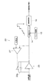
本発明の一実施形態のX線検出信号処理装置を示す概略図である。
同X線検出信号処理装置を用いた蛍光X線分析装置の概略図である。
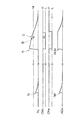
同X線検出信号処理装置における各部からの信号を縦に並べて示す図である。
第1の従来技術であるX線検出信号処理装置を示す概略図である。
第2の従来技術であるX線検出信号処理装置を示す概略図である。
同X線検出信号処理装置における各部からの信号を縦に並べて示す図である。
以下、本発明の一実施形態のX線検出信号処理装置について、図にしたがって説明する。この装置は、図1に示すように、X線検出器からの信号が入力され、X線検出器に入射したX線のエネルギーに応じた波高の信号を出力する装置10であって、X線検出器からの信号を増幅し、CR回路13aの時定数に応じて減衰させるプリアンプ13と、クロック発振器15と、そのクロック発振器15の発振に基づいて動作し、プリアンプ13からの信号を高速AD変換する高速ADコンバーター14と、その高速ADコンバーター14からの信号の立ち上がりに基づいて信号の到達を認識し、到達を認識した信号について、立ち上がりの高さから、換言すればフィルター関数によって平滑化して、波高値を求め、多重波高分析器へ出力する信号処理部16とを備えている。なお、本実施形態では、多重波高分析器に適用する場合の例を示すが、本発明のX線検出信号処理装置は、多重波高分析器(マルチチャンネルアナライザー)に限らず、シングルチャンネルの波高分析器にも適用できる。
このように、本実施形態のX線検出信号処理装置10では、前述の第2の従来技術と同様にCR回路13aを有する連続リセットタイプのプリアンプ13を用いるので、X線検出器からの各信号についてプリアンプ13からの出力レベルを例えば100mV程度に大きくでき、SN比が良好で、高計数率にも対応できる。また、前述したように、プリアンプ13からの信号のレベルが高速ADコンバーター14の入力範囲を超えた場合には、高速ADコンバーター14自身で対処できる。
そして、本実施形態のX線検出信号処理装置10は、さらに、プリアンプ13からの信号のレベルが所定の上限値を超えていない場合にはハイの信号を発し、プリアンプ13からの信号のレベルが前記所定の上限値を超えている場合にはローの信号を発するコンパレーター17と、そのコンパレーター17からの信号がローからハイになるのを所定の時間遅延させてクロック発振器15へ出力し、ローの信号をクロック発振器15へ出力して発振を停止させることにより、高速ADコンバーター14での高速AD変換を停止させて出力値を維持させる制御部18とを備えている。
このコンパレーター17および制御部18を備えたことによる本実施形態のX線検出信号処理装置10の動作について説明する。図3に、本実施形態のX線検出信号処理装置10における、プリアンプ13からの信号Po、コンパレーター17からの信号CMo、制御部18からの信号CKe、高速ADコンバーター14からの信号ADoを縦に並べて示す。縦に並んだ図3の各部において、縦軸は各信号のレベルで、横軸は時間であり、プリアンプ13からの信号Poのレベルが飽和していない有効な範囲にある状態を左側に示し、X線検出器へのX線の入射頻度が高くなり重畳が起こった場合や、X線検出器へ強大なエネルギーの宇宙線が入射した場合であって、プリアンプ13からの信号Poのレベルが飽和していない有効な範囲を超えた状態を右側に示している。なお、コンパレーター17に設定された、プリアンプ13からの信号Poについての所定の上限値をHlで示し、コンパレーター17からの信号CMoおよび制御部18からの信号CKeについて、ハイをHで、ローをLで示している。
図3の左側に示したように、プリアンプ13からの信号Poのレベルが、飽和していない有効な範囲にある状態では、つまり、コンパレーター17に設定された所定の上限値Hl以下であると、コンパレーター17からの信号CMoおよび制御部18からの信号CKeはいずれもハイであり、プリアンプ13からの信号Poの急峻な立ち上がりNがそのまま高速AD変換されて、高速ADコンバーター14からの信号ADoの急峻な立ち上がりNdになる。その急峻な立ち上がりNdに基づいて、信号処理部16は、高速ADコンバーター14からの信号ADoの到達を認識し、到達を認識した信号ADoについてフィルター関数によって平滑化して波高値を求め、多重波高分析器へ出力する。多重波高分析器は、その波高値を正常で有効なものとして処理する。この動作は、前述した第2の従来技術における問題のない動作と同様である。
一方、図3の右側に示したように、プリアンプ13からの信号Poのレベルが、飽和していない有効な範囲を超えると、つまり、コンパレーター17に設定された所定の上限値Hlを超えると、コンパレーター17からの信号CMoおよび制御部18からの信号CKeはいずれもローになる。そして、制御部18からローの信号CKeがクロック発振器15へ出力されると、クロック発振器15は、高速ADコンバーター14を動作させている発振を停止するので、高速ADコンバーター14は高速AD変換を停止して、停止直前の出力値、つまり、プリアンプ13からの信号Poのレベルがコンパレーター17に設定された所定の上限値Hlに達したときの出力値を維持する。その結果、プリアンプ13からの信号Poの急峻な立ち上がりAは、上限値Hlに達するまで高速AD変換されて、高速ADコンバーター14からの信号ADoの急峻な立ち上がりAHldになる。
急峻な立ち上がりAの後の減衰の過程で、プリアンプ13からの信号Poのレベルが、飽和していない有効な範囲に戻ろうとするときに、つまり、コンパレーター17に設定された所定の上限値Hl以下になろうとするときに、プリアンプ13の特性上ノイズ(グリッジ、ザグなどと呼ばれる)として急峻な立ち下がりBおよび急峻な立ち上がりCを生じる。この急峻な立ち下がりBおよび急峻な立ち上がりCにおいて、プリアンプ13からの信号Poのレベルは、コンパレーター17に設定された所定の上限値Hl未満にまで下がってから、再度超えるまで上がるので、コンパレーター17からの信号CMoは、ローからハイになり、すぐまたローに戻る。しかし、制御部18は、コンパレーター17からの信号CMoがローからハイになるのを所定の時間遅延させてクロック発振器15へ出力するので、制御部18からの信号CKeはローのままである。したがって、高速ADコンバーター14は、急峻な立ち上がりAHld終端の出力値を維持し続ける。なお、制御部18に設定される、コンパレーター17からの信号CMoがローからハイになるのを遅延させる所定の時間は、実験的に求めることができ、例えば0.03msecである。
急峻な立ち上がりCの後の減衰の過程で、プリアンプ13からの信号Poのレベルが、飽和していない有効な範囲に戻ると、つまり、コンパレーター17に設定された所定の上限値Hlまで下がると、コンパレーター17からの信号CMoはローからハイになり、前述の所定の時間遅延して、制御部18からの信号CKeもローからハイになる。そして、制御部18からの信号CKeがハイになると、高速ADコンバーター14は、プリアンプ13からの信号Poの高速AD変換を再開するので、高速ADコンバーター14からの信号ADoも、プリアンプ13からの信号Poと同様に減衰していく。
したがって、高速ADコンバーター14からの信号ADoには、最初に急峻な立ち上がりAHldが現れるだけで、これに基づいて、信号処理部16は、高速ADコンバーター14からの信号ADoの到達を認識し、到達を認識した信号ADoについてフィルター関数によって平滑化して波高値を求め、多重波高分析器へ出力する。多重波高分析器において、この波高値は、値の大きさから異常で無効なものとして処理でき、前述の急峻な立ち上がりNdについての波高値と同様に正常で有効なものとして処理されることはないので、エネルギー分解能が劣化するおそれがない。
以上のように、本実施形態のX線検出信号処理装置10では、CR回路13aを有する連続リセットタイプのプリアンプ13を用い、プリアンプ13からの信号Poのレベルが所定の上限値Hlを超えると、制御部18が、高速ADコンバーター14での高速AD変換を停止させて出力を維持させるとともに、その後プリアンプ13からの信号Poのレベルが所定の上限値Hl以下に減衰しても高速AD変換の再開を所定の時間遅延させるので、SN比が良好で、高計数率にも対応でき、しかも、X線検出器へのX線の入射頻度が高くなることや、X線検出器へ宇宙線が入射することがあっても、波高分析器で有効、無効について正しく処理できる波高値のみを出力することによりエネルギー分解能の高い分析ができる。
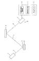
本実施形態のX線検出信号処理装置10は、例えば、図2の蛍光X線分析装置に用いられる。この蛍光X線分析装置は、試料台8に載置された試料3にX線管などのX線源1から1次X線2を照射して発生する蛍光X線4を検出手段9で検出する蛍光X線分析装置であって、前述のX線検出信号処理装置10と、X線検出信号処理装置10からの波高の信号(波高値)について多数の連続した波高範囲ごとに分別して計数率を求めることにより、波高に対する計数率の分布であるエネルギースペクトル(波高分布曲線)を得る多重波高分析器11と、多重波高分析器11で得たエネルギースペクトルに基づいて試料3における成分の含有率等を算出する定量手段12とを備える。X線検出信号処理装置10、多重波高分析器11および定量手段12の少なくとも一部は、具体的には、コンピューターおよびそれに接続された入出力機器で構成される。
検出手段9は、試料3から発生する2次X線4を分光する分光素子5と、分光された2次X線6ごとにそのエネルギー(波長)に応じた波高をもつ信号(パルス)を前記分光された2次X線6の強度に応じた数だけ発生させるX線検出器7で構成される。なお、分光素子5を用いる検出手段9には、検出する2次X線4の波長が固定された固定型と、検出する2次X線4の波長を走査できる走査型とがあるが、必要に応じ、いずれをいくつ備えてもよい。また、分光素子5を用いずに、エネルギー分解能の高いX線検出器を検出手段とすることもできる。この蛍光X線分析装置では、前述のX線検出信号処理装置10を用いるので、前述したのと同様の作用効果が得られる。この蛍光X線分析装置も、本発明の一実施形態であり、本発明に含まれる。また、本発明のX線検出信号処理装置を用いる、蛍光X線分析装置以外のX線分析装置(例えばX線回折装置)も、本発明に含まれる。
以上のとおり、図面を参照しながら好適な実施例を説明したが、当業者であれば、本件明細書を見て、自明な範囲内で種々の変更および修正を容易に想定するであろう。したがって、そのような変更および修正は、添付の請求の範囲から定まるこの発明の範囲内のものと解釈される。
7 X線検出器
10 X線検出信号処理装置
13 プリアンプ
13a CR回路
14 高速ADコンバーター
15 クロック発振器
16 信号処理部
17 コンパレーター
18 制御部
10 X線検出信号処理装置
13 プリアンプ
13a CR回路
14 高速ADコンバーター
15 クロック発振器
16 信号処理部
17 コンパレーター
18 制御部
Claims (2)
- X線検出器からの信号が入力され、前記X線検出器に入射したX線のエネルギーに応じた波高の信号を出力するX線検出信号処理装置であって、
前記X線検出器からの信号を増幅し、CR回路の時定数に応じて減衰させるプリアンプと、
クロック発振器と、
そのクロック発振器の発振に基づいて動作し、前記プリアンプからの信号を高速AD変換する高速ADコンバーターと、
その高速ADコンバーターからの信号の立ち上がりに基づいて信号の到達を認識し、到達を認識した信号についてフィルター関数によって平滑化する信号処理部と、
前記プリアンプからの信号のレベルが所定の上限値を超えていない場合にはハイの信号を発し、前記プリアンプからの信号のレベルが前記所定の上限値を超えている場合にはローの信号を発するコンパレーターと、
そのコンパレーターからの信号がローからハイになるのを所定の時間遅延させて前記クロック発振器へ出力し、ローの信号を前記クロック発振器へ出力して発振を停止させることにより、前記高速ADコンバーターでの高速AD変換を停止させて出力値を維持させる制御部とを備えたX線検出信号処理装置。 - 請求項1に記載のX線検出信号処理装置を用いたX線分析装置。
Priority Applications (2)
| Application Number | Priority Date | Filing Date | Title |
|---|---|---|---|
| CN201580039683.4A CN106537188B (zh) | 2014-07-23 | 2015-05-14 | X射线检测信号处理器和采用它的x射线分析装置 |
| US15/325,787 US9791393B2 (en) | 2014-07-23 | 2015-05-14 | X-ray detection signal processing device and X-ray analyzing apparatus using same |
Applications Claiming Priority (2)
| Application Number | Priority Date | Filing Date | Title |
|---|---|---|---|
| JP2014-149421 | 2014-07-23 | ||
| JP2014149421A JP5874109B2 (ja) | 2014-07-23 | 2014-07-23 | X線検出信号処理装置およびそれを用いたx線分析装置 |
Publications (2)
| Publication Number | Publication Date |
|---|---|
| WO2016013278A1 true WO2016013278A1 (ja) | 2016-01-28 |
| WO2016013278A8 WO2016013278A8 (ja) | 2017-01-19 |
Family
ID=55162817
Family Applications (1)
| Application Number | Title | Priority Date | Filing Date |
|---|---|---|---|
| PCT/JP2015/063893 Ceased WO2016013278A1 (ja) | 2014-07-23 | 2015-05-14 | X線検出信号処理装置およびそれを用いたx線分析装置 |
Country Status (4)
| Country | Link |
|---|---|
| US (1) | US9791393B2 (ja) |
| JP (1) | JP5874109B2 (ja) |
| CN (1) | CN106537188B (ja) |
| WO (1) | WO2016013278A1 (ja) |
Families Citing this family (4)
| Publication number | Priority date | Publication date | Assignee | Title |
|---|---|---|---|---|
| US9933375B2 (en) * | 2015-09-25 | 2018-04-03 | Olympus Scientific Solutions Americas, Inc. | XRF/XRD system with dynamic management of multiple data processing units |
| JP7020357B2 (ja) * | 2018-09-27 | 2022-02-16 | 株式会社島津製作所 | X線分析用信号処理装置 |
| JP7218958B1 (ja) * | 2021-08-24 | 2023-02-07 | 株式会社リガク | X線分析装置及び波高値予測プログラム |
| CN118156358B (zh) * | 2024-05-11 | 2024-08-09 | 山东大学 | SiC半导体探测器、矿石成分分析设备及方法 |
Citations (3)
| Publication number | Priority date | Publication date | Assignee | Title |
|---|---|---|---|---|
| JPH06123778A (ja) * | 1992-10-11 | 1994-05-06 | Horiba Ltd | 放射線検出装置 |
| JPH07239385A (ja) * | 1994-02-28 | 1995-09-12 | Shimadzu Corp | 放射線量測定装置 |
| JP2013113648A (ja) * | 2011-11-28 | 2013-06-10 | Mitsubishi Electric Corp | 放射線測定装置 |
Family Cites Families (6)
| Publication number | Priority date | Publication date | Assignee | Title |
|---|---|---|---|---|
| US4288692A (en) * | 1979-08-06 | 1981-09-08 | Tracor Northern, Inc. | Beam current normalization in an X-ray microanalysis instrument |
| US6486808B1 (en) * | 2001-10-16 | 2002-11-26 | Varian Medical Systems | Data signal amplifier with automatically controllable dynamic signal range |
| DE602004022229D1 (de) * | 2003-09-12 | 2009-09-10 | Canon Kk | Bildlesegerät und Bilderzeugungssystem mittels Röntgenstrahlen |
| US8039787B2 (en) | 2007-08-03 | 2011-10-18 | Pulsetor, Llc | Digital pulse processor slope correction |
| US8477291B2 (en) * | 2009-12-16 | 2013-07-02 | Raytheon Company | System and method for ranging of targets |
| JP6081084B2 (ja) * | 2012-05-28 | 2017-02-15 | シャープ株式会社 | 線量計 |
-
2014
- 2014-07-23 JP JP2014149421A patent/JP5874109B2/ja active Active
-
2015
- 2015-05-14 US US15/325,787 patent/US9791393B2/en active Active
- 2015-05-14 CN CN201580039683.4A patent/CN106537188B/zh active Active
- 2015-05-14 WO PCT/JP2015/063893 patent/WO2016013278A1/ja not_active Ceased
Patent Citations (3)
| Publication number | Priority date | Publication date | Assignee | Title |
|---|---|---|---|---|
| JPH06123778A (ja) * | 1992-10-11 | 1994-05-06 | Horiba Ltd | 放射線検出装置 |
| JPH07239385A (ja) * | 1994-02-28 | 1995-09-12 | Shimadzu Corp | 放射線量測定装置 |
| JP2013113648A (ja) * | 2011-11-28 | 2013-06-10 | Mitsubishi Electric Corp | 放射線測定装置 |
Also Published As
| Publication number | Publication date |
|---|---|
| US9791393B2 (en) | 2017-10-17 |
| WO2016013278A8 (ja) | 2017-01-19 |
| CN106537188B (zh) | 2018-06-01 |
| JP5874109B2 (ja) | 2016-03-02 |
| CN106537188A (zh) | 2017-03-22 |
| US20170153190A1 (en) | 2017-06-01 |
| JP2016024102A (ja) | 2016-02-08 |
Similar Documents
| Publication | Publication Date | Title |
|---|---|---|
| JP5874109B2 (ja) | X線検出信号処理装置およびそれを用いたx線分析装置 | |
| JP6124750B2 (ja) | 放射線検出装置、および試料分析装置 | |
| JP5043728B2 (ja) | 放射線計測用パルスプロセッサ | |
| EP3196636B1 (en) | X-ray analyzing apparatus | |
| EP2282197A3 (en) | Particle beam systems and methods | |
| JP4880077B1 (ja) | X線検出信号処理装置および方法 | |
| JP5945245B2 (ja) | 信号パルス検出装置、質量分析装置、および信号パルス検出方法 | |
| JP2016224009A (ja) | 信号処理装置及びノイズ強度決定方法 | |
| US9983317B2 (en) | Signal processing device and radiation measurement device | |
| US9148549B2 (en) | Image processing method and image processing apparatus using time axis low band pass filter | |
| JP2016114554A (ja) | 中性子測定装置および中性子測定方法 | |
| JP4771796B2 (ja) | パルス信号の波高値検出回路 | |
| US20210360173A1 (en) | Radiation imaging system, control apparatus, and control method | |
| JP2016090555A (ja) | 中性子測定装置および中性子測定方法 | |
| JP4928502B2 (ja) | 液体シンチレーションカウンタ | |
| JP7534994B2 (ja) | パルス波高分析装置及び放射線測定装置 | |
| JP6999593B2 (ja) | 検出装置及びスペクトル生成装置 | |
| US11898991B2 (en) | Inspection device and inspection method | |
| US7990529B2 (en) | Detection circuit and foreign matter inspection apparatus for semiconductor wafer | |
| ITVE20090050A1 (it) | Spettrometro di massa ad ampio intervallo di dinamica.- | |
| JP2007040720A (ja) | 光電センサ | |
| JP2014169877A (ja) | X線検出装置および試料分析装置 | |
| US11703479B2 (en) | Inspection device, processing device and inspection method | |
| US9464996B2 (en) | Processing device and method for the spectrometric measurement of a photon flux | |
| WO2017098781A1 (ja) | 厚さ測定装置 |
Legal Events
| Date | Code | Title | Description |
|---|---|---|---|
| 121 | Ep: the epo has been informed by wipo that ep was designated in this application |
Ref document number: 15824018 Country of ref document: EP Kind code of ref document: A1 |
|
| WWE | Wipo information: entry into national phase |
Ref document number: 15325787 Country of ref document: US |
|
| NENP | Non-entry into the national phase |
Ref country code: DE |
|
| 122 | Ep: pct application non-entry in european phase |
Ref document number: 15824018 Country of ref document: EP Kind code of ref document: A1 |