WO2016013242A1 - 距離測定装置及び距離測定方法 - Google Patents
距離測定装置及び距離測定方法 Download PDFInfo
- Publication number
- WO2016013242A1 WO2016013242A1 PCT/JP2015/055365 JP2015055365W WO2016013242A1 WO 2016013242 A1 WO2016013242 A1 WO 2016013242A1 JP 2015055365 W JP2015055365 W JP 2015055365W WO 2016013242 A1 WO2016013242 A1 WO 2016013242A1
- Authority
- WO
- WIPO (PCT)
- Prior art keywords
- light
- pulse
- distance
- measurement
- pulse signal
- Prior art date
Links
Images


Classifications
-
- G—PHYSICS
- G01—MEASURING; TESTING
- G01C—MEASURING DISTANCES, LEVELS OR BEARINGS; SURVEYING; NAVIGATION; GYROSCOPIC INSTRUMENTS; PHOTOGRAMMETRY OR VIDEOGRAMMETRY
- G01C3/00—Measuring distances in line of sight; Optical rangefinders
- G01C3/02—Details
- G01C3/06—Use of electric means to obtain final indication
-
- G—PHYSICS
- G01—MEASURING; TESTING
- G01S—RADIO DIRECTION-FINDING; RADIO NAVIGATION; DETERMINING DISTANCE OR VELOCITY BY USE OF RADIO WAVES; LOCATING OR PRESENCE-DETECTING BY USE OF THE REFLECTION OR RERADIATION OF RADIO WAVES; ANALOGOUS ARRANGEMENTS USING OTHER WAVES
- G01S17/00—Systems using the reflection or reradiation of electromagnetic waves other than radio waves, e.g. lidar systems
- G01S17/02—Systems using the reflection of electromagnetic waves other than radio waves
- G01S17/06—Systems determining position data of a target
- G01S17/08—Systems determining position data of a target for measuring distance only
- G01S17/10—Systems determining position data of a target for measuring distance only using transmission of interrupted, pulse-modulated waves
-
- G—PHYSICS
- G01—MEASURING; TESTING
- G01S—RADIO DIRECTION-FINDING; RADIO NAVIGATION; DETERMINING DISTANCE OR VELOCITY BY USE OF RADIO WAVES; LOCATING OR PRESENCE-DETECTING BY USE OF THE REFLECTION OR RERADIATION OF RADIO WAVES; ANALOGOUS ARRANGEMENTS USING OTHER WAVES
- G01S7/00—Details of systems according to groups G01S13/00, G01S15/00, G01S17/00
- G01S7/48—Details of systems according to groups G01S13/00, G01S15/00, G01S17/00 of systems according to group G01S17/00
- G01S7/497—Means for monitoring or calibrating
Definitions
- the present invention projects a projection pulse on a measurement target, receives the projection pulse reflected by the measurement target as a light reception pulse, and calculates a time difference from when the projection pulse is projected until the reception pulse is received.
- the present invention relates to a distance measuring device and a distance measuring method for measuring and calculating a distance to a measuring object.
- a light projection pulse radiated from a pulse-driven laser or other light source is projected onto a measurement object by a scanning mechanism and reflected by the measurement object.
- the light receiving element receives the light pulse as a light receiving pulse.
- the distance from the distance measuring device to the measurement target is calculated based on the speed of light in the air by measuring the time difference from when the light projection pulse is projected until the light reception pulse is received.
- Such a method of measuring the distance to the measurement target is called a time flight method.
- the signal intensity of the received light pulse signal based on the received light pulse decreases in inverse proportion to the square of the distance to the measurement object. Further, the signal intensity varies depending on the reflectance and surface state of the measurement object. For this reason, the received light pulse signal has an extremely wide range of intensity from a very large level to a small level. For this reason, the distance measuring device needs to measure the distance to the measurement object based on various received light pulse signals having signal intensities in a very wide range and different characteristics.
- Patent Document 1 discloses that the peak intensity of the light reception pulse signal is compared with the peak intensity of the reference pulse signal.
- a technique for adjusting the amplification factor of the received light pulse signal so that the intensity is approximately the same as the peak intensity of the reference pulse signal is disclosed.
- the above-mentioned problem that variations and deviations occur in the measured distance has a very wide range of intensity from a very large level to a small level, and various received light pulses with different intensities. This arises from the need to measure the distance to the measurement object based on the signal.
- Patent Document 1 the intensity of the received light pulse signal is used as an index, and the gain of the received light pulse signal is changed based on the intensity of the received light pulse signal.
- this method has the following problems.
- the received light pulse signal has a very wide dynamic range from a very strong level to a very weak level. Therefore, when the received light pulse signal intensity is high, the measured intensity is saturated, and conversely, the received light pulse signal intensity. If is weak, there may be a problem such as insufficient measurement sensitivity. For this reason, there is a problem that it is generally very difficult to accurately measure the intensity of the received light pulse signal having such a wide dynamic range. Alternatively, there is a problem that the configuration of the distance measuring device becomes complicated in order to measure the received light pulse signal having such a wide dynamic range even if it can be measured accurately.
- the present invention has been made in view of the above-described problems, and its object is to easily reduce the intensity of a received pulse signal having an extremely wide dynamic range in a distance measuring apparatus that measures a distance by a time flight method by scanning a laser.
- An object of the present invention is to provide a distance measuring device and a distance measuring method that can be determined with a simple configuration and reduce variations and deviations in measurement distance.
- a distance measuring device includes a light emitting element that projects a light projection pulse on a measurement target, and a light reception pulse that receives the light projection pulse reflected by the measurement target.
- a light receiving unit that generates a light reception pulse signal based on the light reception pulse, a pulse width calculation unit that calculates a pulse width of the light reception pulse signal based on a predetermined threshold, and a pulse width of the light reception pulse signal.
- a time difference measurement unit that measures a time difference and a distance calculation unit that calculates the distance based on the time difference are provided.
- a distance measuring method includes a light projecting step of projecting a light projection pulse on a measurement target, and the light projection pulse reflected by the measurement target as a light reception pulse.
- a measurement condition designating step for designating a measurement condition for measuring the distance to the measurement object, and from the light projection pulse to the light reception pulse being received based on the measurement condition
- the intensity of a received light pulse signal having an extremely wide dynamic range is determined with a simple configuration, and the measurement distance varies. There is an effect that the deviation can be reduced.
- (A) is a perspective sectional view of the distance measuring device concerning Embodiment 1, and (b) is the front sectional view. It is a schematic diagram which shows the structure of the said distance measuring device. It is a block diagram which shows the structure of the said distance measurement apparatus. It is a wave form diagram which shows the light projection pulse signal and light reception pulse signal of the said distance measuring device. It is a block diagram which shows the structure of the arithmetic processing unit provided in the said distance measuring device.
- (A) is a waveform diagram showing a saturated received light pulse signal
- (b) is a waveform diagram showing a received light pulse signal when the received light amount is large
- (c) is a received light pulse signal when the received light amount is small.
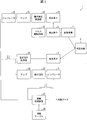
- FIG. 1A is a perspective sectional view of the distance measuring device 1 according to the first embodiment, and FIG. 1B is a front sectional view thereof.
- FIG. 2 is a schematic diagram showing the configuration of the distance measuring device 1.
- FIG. 3 is a block diagram thereof.
- the distance measuring device 1 includes a housing 29.
- the housing 29 is provided with the light emitting element 2.
- a semiconductor laser is generally used as the light emitting element 2, but a light emitting element such as an LED (Light Emitting Diode) may be used to measure a short distance.
- the light emitting element 2 is pulse-driven by the pulse driving circuit 10 and emits light.
- the light emitted from the light emitting element 2 is adjusted to substantially divergent light by the light projecting lens 12, bent 90 degrees by the bending mirror 13, and projected as a light projection pulse to the measuring object 9 through the scanning mechanism 11.
- the scanning mechanism 11 includes a mirror 14 that further folds the divergent light bent 90 degrees by the bending mirror 13, a diaphragm 15 that passes the divergent light bent by the mirror 14, and a motor 18 that rotates the mirror 14 and the diaphragm 15. Including.
- the divergent light that has passed through the diaphragm 15 passes through the translucent member 16 provided in the housing 29 and is projected onto the measurement object 9 as a light projection pulse.
- the scanning mechanism 11 is configured to project the light projection pulse two-dimensionally onto the measurement target 9 by rotating and scanning the mirror 14 and the diaphragm 15 attached to the motor 18.
- the light projection pulse reflected by the measurement object 9 is transmitted as a light reception pulse through the translucent member 16, reflected by the mirror 14, condensed by the light receiving lens 17, and guided to the light receiving element (light receiving unit) 3.
- a part of the light emitted from the light emitting element 2 is guided to the light receiving element 19 to generate a light receiving pulse signal.
- the light emitting element 2 and the light receiving element 19 are desirably arranged on the same substrate. Further, it is preferable to use elements having the same specifications for the light receiving element 3 and the light receiving element 19 in consideration of the temperature characteristics.
- the diaphragm 15 between the mirror 14 and the translucent member 16 is provided so that the light reflected and scattered by the surfaces of the mirror 14 and the translucent member 16 does not go to the light receiving element 3.
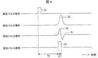
- FIG. 4 is a waveform diagram showing the light projection pulse signal S1 and the light reception pulse signals S2 to S4 of the distance measuring device 1.
- the light received by the light receiving element 19 is converted into a current signal, converted into a voltage signal by a current / voltage converter 20, amplified by an amplifier 21, and projected by a comparator 22 defined by a predetermined threshold value. (Digital signal).
- the light reception pulse reflected by the measuring object 9 is received by the light receiving element 3 and converted into a current signal, converted into a voltage signal by a current-voltage converter (light receiving unit) 23, and then amplified by an amplifier (light receiving unit) 24.
- the light reception pulse signal S2 is obtained.
- the received light pulse signal S2 is further differentiated by a differentiation circuit (light receiving unit) 25 to become a received light pulse signal S3, and then the pulse width is measured by a comparator (pulse width calculating unit) 4 defined by a predetermined threshold. , Converted into a received light pulse signal S4 (digital signal).
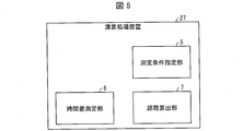
- FIG. 5 is a block diagram illustrating a configuration of the arithmetic processing device 27 provided in the distance measuring device 1.
- the light reception pulse signal S 1 output from the comparator 22 and the light reception pulse signal S 4 output from the comparator 4 are input to the arithmetic processing unit 27.
- the arithmetic processing unit 27 calculates the time difference T0 between the received light pulse signals S1 and S4 output from the comparator 22 and the comparator 4, converts it into a distance, performs a distance measurement operation a predetermined number of times, and calculates an average value of a plurality of measurement results, Then, the variation is obtained, and the average value is output as the measurement distance.
- the arithmetic processing unit 27 has a measurement condition designating unit 5, a time difference measuring unit 6, and a distance calculating unit 7.
- the measurement condition designating unit 5 designates measurement conditions for measuring the distance to the measurement object 9 based on the pulse width of the received light pulse signal S3 measured by the comparator 4.
- the time difference measuring unit 6 is based on the measurement conditions designated by the measurement condition designating unit 5 until the light receiving pulse is received by the light receiving element 3 after the light emitting pulse is projected from the light emitting element 2 to the measuring object 9. Measure the time difference.
- the distance calculation unit 7 calculates the distance from the distance measurement device 1 to the measurement object 9 based on the time difference measured by the time difference measurement unit 6.
- the time difference measurement unit 6 uses the light projection pulse signal S1 and the light reception pulse for the number of measurements. A time difference corresponding to the number of times of measurement is measured with the signal S4, and an average time difference obtained by averaging the time difference corresponding to the number of times of measurement is calculated.
- the distance calculation unit 7 calculates the distance from the distance measurement device 1 to the measurement object 9 based on the average time difference calculated by the time difference measurement unit 6.
- FIG. 6A is a waveform diagram showing a saturated light reception pulse signal S3 (positive component)
- FIG. 6B is a waveform diagram showing a light reception pulse signal S3 (positive component) when the amount of received light is large
- (C) is a waveform diagram showing a received light pulse signal S3 (its positive component) when the amount of received light is small.
- the pulse width of the light reception pulse signal S3 varies depending on the reflectance of the measurement target 9 when the threshold Th of the comparator 4 is fixed. As shown in FIG. 6 (a), when the reflectance of the measurement object 9 is high and the light receiving element 3 receives a large amount of light, the light receiving circuit of the light receiving element 3 is saturated, so that the light receiving pulse signal S3 reaches the saturation level. Has strength A1.
- the received light pulse signal S3 has a pulse width T1 based on the threshold value Th. Then, the light reception pulse signal S4 is generated based on the pulse width T1 of the light reception pulse signal S3.
- the light receiving pulse signal S3 when the light receiving element 3 receives a large amount of light but the light receiving circuit of the light receiving element 3 is not saturated, the light receiving pulse signal S3 has an intensity A2 smaller than the intensity A1.
- the light reception pulse signal S3 has a pulse width T2 that is narrower than the pulse width T1. Then, the light reception pulse signal S4 is generated based on the pulse width T2 of the light reception pulse signal S3.
- the received light pulse signal S3 has an intensity A3 that is smaller than the intensity A2.
- the light reception pulse signal S3 has a pulse width T3 that is narrower than the pulse width T2. Then, the light reception pulse signal S4 is generated based on the pulse width T3 of the light reception pulse signal S3.
- FIG. 7 is a graph showing the relationship between the peak value of the received light pulse signal S3 and the pulse width.
- the horizontal axis indicates the intensity (crest value) of the light reception pulse signal S3, and the vertical axis indicates the pulse width of the light reception pulse signal S3.
- the curve C1 in FIG. 7 it can be seen that when the reflectance of the measuring object 9 decreases, the amount of light received by the light receiving element 3 decreases, and the pulse width of the light receiving pulse signal S3 also decreases from T1 to Tn.
- FIG. 8 is a diagram showing the information table 28 of the distance measuring device 1.
- the measurement object 9 having a known reflectance is arranged at a specific measurement distance, and the pulse width of the light reception pulse signal S3 is measured, whereby the specific measurement distance to the measurement object 9 and The relationship between the pulse width of the light reception pulse signal S3 and the reflectance of the measurement object 9 is obtained and recorded.
- the measurement distance D1 is 1 m
- the measurement distance D2 is 3 m
- the measurement distance D3 is 7 m
- the reflectance R1 is 90. %
- a known measurement object 9 having a reflectance R2 of 50% and a reflectance R3 of 10% is arranged for the distance measuring device 1.
- the reflectance m and the measurement distance type n of the known measurement object 9 are preferably large, but the reflection of the measurement object 9 is considered in consideration of the time required to create the information table 28 and the capacity of the memory storing the information table 28.
- the rate m and the measurement distance type n are preferably about 3 to 5.
- the intensity of the received light pulse signal decreases in inverse proportion to the square of the measured distance. Therefore, as the measurement distance becomes longer, the noise intensity of the distance measurement device appears to be relatively larger, the signal-to-noise ratio becomes smaller, and the distance measurement accuracy decreases.
- a method of increasing the signal-to-noise ratio is generally used by measuring the distance a plurality of times and adding an averaging process of the measured distance to reduce random noise.
- the number of averaging processes (the number of times of distance measurement) is changed so that the measurement distance is Even if the measurement object 9 has a low reflectance and a low signal-to-noise ratio, or when the measurement object 9 has a high reflectance and the measurement distance is large and the signal-to-noise ratio is small, the number of averaging processes ( The number of distance measurements) is increased.
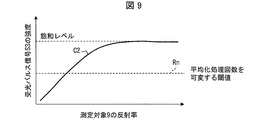
- FIG. 9 is a graph showing the relationship between the reflectance of the measuring object 9 of the distance measuring device 1 and the intensity (peak value) of the received light pulse signal S3.
- the reflection of the measurement object 9 is reflected.
- the time difference measurement unit 6 is configured to increase the number of averaging processes and increase the reliability of data.
- the intensity of the light reception pulse signal S3 is smaller as the measurement distance to the measurement object 9 is farther, that is, the pulse width of the light reception pulse signal S3 is narrower.
- a distance measuring apparatus 1 having a threshold value Rn of the intensity of the received light pulse signal S3 corresponding to the reflectance that increases the number of times of averaging processing as 10% is given as a specific example.
- the distance D to the measurement object 9 is determined as 3 m from the time difference between the light projection pulse signal S1 and the light reception pulse signal S4.
- the pulse width T of the light reception pulse signal S3 is also measured.
- the distance D to the measurement object 9 is determined by the time difference between the light projection pulse signal S1 and the light reception pulse signal S4. It is determined as 3m.
- the reflectance of the measurement target 9 is less than 10%. I understand that it is small.
- the reflectance threshold for increasing the number of averaging processes is 10%, the reflectance of the measurement object 9 is low, the signal strength is low, the signal-to-noise ratio is small, and the data is regarded as low-reliability data. Increase the number of digitization processes to ensure a signal-to-noise ratio.
- the distance measuring device that measures the distance based on the received light pulse reflected by the measuring object 9 is the distance to the measuring object 9, Due to the light reflectance, the intensity of the received light pulse has a very wide dynamic range.
- the problem when the intensity of the received pulse fluctuates is that when the intensity is small, (1) Since the signal-to-noise ratio (S / N ratio) of the received light pulse deteriorates, the measurement position varies and the position accuracy decreases. (2) When measuring the rising timing of the received light pulse signal, the timing is shifted so as to be delayed.
- Patent Document 1 the problem (2) is solved by measuring the peak intensity of the received light pulse signal and adjusting the magnification of the received light pulse signal based on the peak intensity.
- the peak intensity is high, the measured signal intensity is saturated. For example, the signal intensity having a very wide dynamic range is obtained. Accurate measurement is actually difficult.
- this problem is solved not by measuring the peak intensity of the received light pulse signal but by measuring the pulse width of the received light pulse signal.
- it can be accurately measured even if the peak portion of the received light pulse signal is saturated.
- a pulse signal having a large intensity generally has a large pulse width. Therefore, by measuring the pulse width without measuring the peak intensity, the intensity of the received light pulse signal can be accurately estimated even when the intensity of the received light signal has a wide dynamic range. Is used in the present embodiment.
- the distance measuring device measures a time difference between the light projection pulse signal and the light reception pulse signal using a comparator, and measures the distance based on the measured time difference.
- a comparator that measures the time difference between the light projection pulse signal and the light reception pulse signal can be used in common with the pulse width measurement. For this reason, this embodiment does not require the addition of components for measuring the pulse width, and can be realized with a simple device configuration.
- Patent Document 1 there is a problem that an additional circuit member for measuring the peak intensity is necessary and a configuration for supporting a wide dynamic range is additionally required.
- Patent Document 1 in order to solve the problem (2), the peak intensity is measured, and the amplification factor of the received light pulse signal is adjusted based on the peak intensity.
- the noise level is also amplified, and thus the problem (1) cannot be solved.
- the intensity of the received light pulse signal is weak, the number of measurements is increased, and the measurement results of these multiple measurements are averaged, thereby solving the problem (1) and improving the measurement accuracy. Improve.
- the time difference between the light projection pulse signal S1 and the light reception pulse signal S4 is calculated by calculating the average value of the time difference between the light projection pulse signal S1 and the light reception pulse signal S4 and then calculating the distance using the average value.
- a method is conceivable in which, after calculating the distance based on the above, an average value of distances corresponding to the number of times of measurement is calculated as the calculated distance.
- there are various averaging processing methods other than simply taking an average value such as excluding a value greatly deviating from the median value from being used for calculating the average value.
- FIG. 10 is a block diagram illustrating a configuration of the arithmetic processing device 27a provided in the distance measuring device according to the second embodiment.
- the arithmetic processing device 27a includes a measurement condition specifying unit 5a instead of the measurement condition specifying unit 5 of the arithmetic processing device 27 shown in FIG.
- the measurement condition designating unit 5a provided in the arithmetic processing unit 27a designates the peak intensity of the projection pulse as the measurement condition.
- the light emitting element 2 projects the light projection pulse having the peak intensity designated by the measurement condition designating unit 5 a onto the measurement object 9.
- the peak intensity of the projected pulse projected onto the measurement object 9 is increased as necessary, the signal-to-noise ratio is increased, and the measurement distance accuracy is increased. Is possible.
- the pulse width may be shortened simultaneously with increasing the peak intensity of the light projection pulse to be projected.
- the distance to the measurement object 9 is based on the time difference between the light projection pulse signal S1 and the light reception pulse signal S4. D is 3m.
- the reflectance threshold for increasing the number of times of averaging processing is 10%. Therefore, the reflectance of the measuring object 9 is low, the signal level is low, the signal-to-noise ratio is small, and the data is regarded as low reliability. Then, the accuracy of the measurement distance can be improved by shortening the pulse width of the projection pulse projected onto the measuring object 9, increasing the peak intensity while keeping the average output constant, and increasing the signal level of the projection pulse. It becomes possible.
- the light emitting element 2 is configured by a gate IC (Integrated Circuit) that drives a laser current
- a pulse signal generator for example, a PWM (Pulse Width Modulation) signal generator of a microcomputer
- a pulse signal By changing the pulse width generated by the generator in a software manner, the pulse width of the laser beam representing the light projection pulse can be changed.
- the laser drive current may be configured so that the amount of current can be varied according to the pulse width. For example, when the pulse width is 20 ns (nanoseconds) and the drive current at peak output is 5 A (ampere), and the pulse width is reduced to 5 ns (nanoseconds), the drive current at peak output is 20 A (ampere). ), The signal-to-noise ratio can be increased while keeping the average output constant.
- This embodiment solves the problem of the present invention by controlling the intensity of the light projection pulse to be increased when the pulse width of the received light pulse signal is narrow.
- the pulse width of the light reception pulse signal is narrow, that is, when the intensity of the light reception pulse signal is low, in principle, the intensity of the light reception pulse is increased by increasing the intensity of the light projection pulse. be able to.
- the light projection is performed only when the pulse width of the light reception pulse signal is narrow, that is, when the light reception pulse signal intensity is low. An operation that increases the peak intensity of the pulse is assumed.
- FIG. 11 is a block diagram illustrating a configuration of the arithmetic processing device 27b provided in the distance measuring device according to the third embodiment.
- the arithmetic processing unit 27b includes a measurement condition designating unit 5b, a time difference measuring unit 6, a time difference correcting unit 8, and a distance calculating unit 7b.
- the time difference measuring unit 6 is the same as the time difference measuring unit 6 of the arithmetic processing unit 27 shown in FIG.
- the measurement condition designating unit 5b designates a timing correction amount for correcting a change in the rising timing of the light reception pulse signal S3 based on the pulse width of the light reception pulse signal S3.
- the time difference correcting unit 8 corrects the time difference measured by the time difference measuring unit 6 based on the timing correction amount specified by the measurement condition specifying unit 5b.
- the distance calculation unit 7 b calculates the distance to the measurement object 9 based on the time difference corrected by the time difference correction unit 8.
- the number of times of averaging processing is varied according to the signal level of the light reception pulse signal S3 obtained from the pulse width of the light reception pulse signal S3.
- the signal level of the light reception pulse signal S3 changes and the light reception pulse signal S3 rises.
- the threshold Th of the comparator 4 is fixed due to a change in the slope of the signal, an error occurs in the time difference between the light projection pulse signal S1 and the light reception pulse signal S4, and the accuracy of the measurement distance deteriorates. .
- the time difference correction amount corresponding to the pulse width of the received light pulse signal S3 is calculated theoretically or experimentally as a function of the pulse width or a correction information table, and is corrected when calculating the distance. This makes it possible to increase the distance accuracy.
- the distance according to the present embodiment is a solution to the problem that the accuracy of the measurement distance is reduced when the signal to noise ratio is reduced.
- the measuring device can increase the number of averaging processes.
- Patent Document 1 measures the peak intensity of a received light pulse signal and adjusts the amplification factor of the received light pulse signal according to the peak intensity.
- the receiver voltage is adjusted to adjust the amplification factor of the received light pulse signal.
- a circuit or a circuit for adjusting the magnification of the amplifier that amplifies the received light pulse signal is required.
- such a circuit is not required, and a correction amount corresponding to the pulse width of the light reception pulse signal is calculated, and correction is made for the time difference from when the light projection pulse is projected until the light reception pulse is received. Make corrections based on volume.
- the decrease in the pulse width of the light reception pulse signal and the delay in the rise timing of the light reception pulse signal occur according to the same principle. Therefore, there is a very strong correlation between the amount of decrease in the pulse width of the light reception pulse signal and the amount of delay in the rise timing of the light reception pulse signal. According to the method of the present embodiment, the delay of the rising timing of the received light pulse signal can be corrected with very high accuracy, and an accurate distance can be measured.
- the distance measuring apparatus 1 receives a light emitting element 2 that projects a light projection pulse on a measurement target 9 and a light projection pulse reflected by the measurement target 9 as a light reception pulse.
- a light receiving unit (light receiving element 3, current / voltage converter 23, amplifier 24, differentiation circuit 25) that generates a light receiving pulse signal S3 based on the pulse, and a pulse width of the light receiving pulse signal S3 based on a predetermined threshold Th.
- a pulse width calculation unit (comparator 4) to be calculated, and measurement condition designating units 5, 5a, 5b for designating measurement conditions for measuring the distance to the measurement object 9 based on the pulse width of the received light pulse signal S3.
- a time difference measuring unit 6 for measuring a time difference from when the light projection pulse is projected until the light reception pulse is received based on the measurement condition, and calculating the distance based on the time difference. And a that the distance calculation section 7 ⁇ 7b.
- the measurement conditions for measuring the distance to the measurement target are specified based on the pulse width of the received light pulse signal.
- the pulse width and intensity of the received light pulse signal have a correlation. For this reason, measurement conditions can be changed based on the intensity of the received light pulse signal. Therefore, it is possible to accurately measure the intensity of the received pulse signal with a wide dynamic range with a simple configuration and change the measurement conditions according to the intensity of the received pulse signal to reduce the variation and deviation of the measurement distance.
- a measuring device can be provided.
- the distance measuring device 1 according to aspect 2 of the present invention is the distance measuring apparatus 1 according to aspect 1, in which the measurement condition designating unit designates the number of measurements representing the number of times the distance is measured as the measurement condition, and the time difference measuring unit 6 is , Measuring the time difference for the measurement number of times by the light projection pulse signal and the light reception pulse signal based on the light projection pulse for the number of measurement times, and calculating the average time difference by averaging the time difference for the measurement number of times, The distance calculation unit 7 may calculate the distance based on the average time difference.
- the number of measurements is increased and the averaging process can be executed to reduce variations in measurement distance and deviation.
- the measurement condition designating unit designates the peak intensity of the projection pulse as the measurement condition
- the light emitting element 2 designates the measurement condition.
- the projecting pulse having the peak intensity specified by the unit 5a may be projected onto the measuring object 9.
- the measurement condition designating unit designates a timing correction amount for correcting a change in rising timing of the received light pulse signal as the measurement condition
- the measurement The time difference correcting unit 8 further corrects the time difference based on the timing correction amount specified by the condition specifying unit 5b
- the distance calculating unit 7b calculates the distance based on the time difference corrected by the time difference correcting unit 8. It may be calculated.
- a distance measuring method is based on a light projecting step of projecting a light projection pulse on a measurement object, and receiving a light projection pulse reflected by the measurement object as a light reception pulse.
- a light receiving step for generating a light receiving pulse signal, a pulse width calculating step for calculating a pulse width of the light receiving pulse signal based on a predetermined threshold, and a step up to the measurement object based on the pulse width of the light receiving pulse signal.
- a measurement condition designating step for designating a measurement condition for measuring a distance; a time difference measuring step for measuring a time difference from when the light projection pulse is projected until the light reception pulse is received based on the measurement condition; And a distance calculating step of calculating the distance based on the time difference.
- the present invention projects a light projection pulse on a measurement object, receives the light projection pulse reflected by the measurement object as a light reception pulse, and emits the light projection pulse until the light reception pulse is received.
- the present invention can be used in a distance measuring apparatus and a distance measuring method for measuring a time difference and calculating a distance to the measurement target.
Landscapes
- Physics & Mathematics (AREA)
- Engineering & Computer Science (AREA)
- General Physics & Mathematics (AREA)
- Radar, Positioning & Navigation (AREA)
- Remote Sensing (AREA)
- Electromagnetism (AREA)
- Computer Networks & Wireless Communication (AREA)
- Optical Radar Systems And Details Thereof (AREA)
Abstract
測定距離のばらつき、ずれを低減する。所定の閾値により受光パルス信号のパルス幅を算出するコンパレータ(4)と、受光パルス信号のパルス幅に基づいて距離を測定する測定条件を指定する測定条件指定部(5)と、測定条件に基づいて、投光パルスが投光されてから受光パルスが受光されるまでの時間差を測定する時間差測定部(6)と、時間差により距離を算出する距離算出部(7)とを備える。
Description
本発明は、測定対象に投光パルスを投光し、測定対象により反射された投光パルスを受光パルスとして受光し、投光パルスが投光されてから受光パルスが受光されるまでの時間差を測定して測定対象までの距離を算出する距離測定装置及び距離測定方法に関する。
この種の一般的な距離測定装置(測距装置)においては、パルス駆動されたレーザ等の光源から放射された投光パルスを走査機構により測定対象に投光し、測定対象により反射された投光パルスを受光パルスとして受光素子により受光する。そして、投光パルスが投光されてから受光パルスが受光されるまでの時間差を測定することにより、空気中の光速に基づいて距離測定装置から測定目標までの距離が算出される。このような測定目標までの距離の測定方法を時間飛行法という。
受光パルスに基づく受光パルス信号は、測定対象までの距離の2乗に反比例して信号強度が減少する。さらに、測定対象の反射率、表面状態によっても信号強度が変化する。このため、受光パルス信号は、非常に大きいレベルから小さいレベルまで極めて広い範囲の強度を有することになる。このため、距離測定装置は、このように非常に広い範囲の信号強度を有し特性が異なる様々な受光パルス信号に基づいて、測定対象までの距離を測定する必要がある。
上記の必要性に起因して、測定対象からの受光パルス信号の強度が非常に弱い場合は、信号対雑音比が増大するので、測定した距離にばらつきが発生する。さらには、受光パルス信号の立ち上がり時間を測定することにより上記距離を測定する場合、受光パルス信号の強度が弱い場合は、上記立ち上がり時間が長くなることによる時間のずれが発生し、測定した測定対象までの距離にずれが生じる。
上記の受光パルス信号の立ち上がり時間のずれに起因した測定距離のずれを解消するため、特許文献1には、受光パルス信号のピーク強度を基準パルス信号のピーク強度と比較し、受光パルス信号のピーク強度が基準パルス信号のピーク強度と同程度になるように受光パルス信号の増幅率を調整する技術が開示されている。
上述のように、測定した距離に、ばらつき、ずれが生じるという上記課題は、受光パルス信号が非常に大きいレベルから小さいレベルまで極めて広い範囲の強度を有しており、強度が異なる様々な受光パルス信号に基づいて測定対象までの距離を測定する必要性から生じるものである。
本課題を解決するためには、受光パルス信号の強度を所定の指標に基づいて判定し、判定された受光パルス信号の強度に応じて、距離を測定するための測定条件を変更することが望ましい。
特許文献1では、受光パルス信号の強度を指標とし、受光パルス信号の強度に基づいて受光パルス信号の増幅率を変更している。しかしながら、この方法には下記の問題点がある。
受光パルス信号は、非常に強いレベルから微弱なレベルまで極めて広いダイナミックレンジを有するものであるので、受光パルス信号の強度が強い場合は測定される強度が飽和し、逆に、受光パルス信号の強度が弱い場合は測定の感度が不足するなどの問題が想定される。このため、このように広いダイナミックレンジを有する受光パルス信号の強度を正確に測定することは一般的に非常に困難であるという問題がある。あるいは、正確に測定可能であっても、このように広いダイナミックレンジを有する受光パルス信号を測定するために、測距装置の構成が複雑なものとなるという問題が生じる。
本発明は上記の問題を鑑みてなされたものであり、その目的は、レーザを走査して時間飛行法により距離を測定する距離測定装置において、極めて広いダイナミックレンジを有する受光パルス信号の強度を簡単な構成で判定し、測定距離のばらつき、ずれを低減することができる距離測定装置及び距離測定方法を提供することにある。
上記の課題を解決するために、本発明の一態様に係る距離測定装置は、測定対象に投光パルスを投光する発光素子と、前記測定対象により反射された投光パルスを受光パルスとして受光して、前記受光パルスに基づく受光パルス信号を生成する受光部と、予め定められた閾値に基づいて前記受光パルス信号のパルス幅を算出するパルス幅算出部と、前記受光パルス信号のパルス幅に基づいて、前記測定対象までの距離を測定するための測定条件を指定する測定条件指定部と、前記測定条件に基づいて、前記投光パルスが投光されてから受光パルスが受光されるまでの時間差を測定する時間差測定部と、前記時間差に基づいて前記距離を算出する距離算出部とを備えたことを特徴とする。
上記の課題を解決するために、本発明の一態様に係る距離測定方法は、測定対象に投光パルスを投光する投光工程と、前記測定対象により反射された投光パルスを受光パルスとして受光して、前記受光パルスに基づく受光パルス信号を生成する受光工程と、予め定められた閾値に基づいて前記受光パルス信号のパルス幅を算出するパルス幅算出工程と、前記受光パルス信号のパルス幅に基づいて、前記測定対象までの距離を測定するための測定条件を指定する測定条件指定工程と、前記測定条件に基づいて、前記投光パルスが投光されてから受光パルスが受光されるまでの時間差を測定する時間差測定工程と、前記時間差に基づいて前記距離を算出する距離算出工程とを包含することを特徴とする。
本発明の一態様によれば、レーザを走査して時間飛行法により距離を測定する距離測定装置において、極めて広いダイナミックレンジを有する受光パルス信号の強度を簡単な構成で判定し、測定距離のばらつき、ずれを低減することができるという効果を奏する。
以下、本発明の実施の形態について、詳細に説明する。
〔実施形態1〕
図1(a)は実施形態1に係る距離測定装置1の斜視断面図であり、(b)はその正面断面図である。図2は距離測定装置1の構成を示す模式図である。図3は、そのブロック図である。
図1(a)は実施形態1に係る距離測定装置1の斜視断面図であり、(b)はその正面断面図である。図2は距離測定装置1の構成を示す模式図である。図3は、そのブロック図である。
(距離測定装置1の光学系の構成)
距離測定装置1は、筐体29を備えている。筐体29には発光素子2が設けられている。発光素子2は、一般的に半導体レーザが使用されているが、近距離を測定するためにはLED(Light Emitting Diode、発光ダイオード)などの発光素子を用いてもよい。発光素子2はパルス駆動回路10によりパルス駆動されて光を放射する。発光素子2から放射された光は、投光レンズ12により略発散光に調整され、折り曲げミラー13により90度折り曲げられ、走査機構11を通じて測定対象9に投光パルスとして投光される。
距離測定装置1は、筐体29を備えている。筐体29には発光素子2が設けられている。発光素子2は、一般的に半導体レーザが使用されているが、近距離を測定するためにはLED(Light Emitting Diode、発光ダイオード)などの発光素子を用いてもよい。発光素子2はパルス駆動回路10によりパルス駆動されて光を放射する。発光素子2から放射された光は、投光レンズ12により略発散光に調整され、折り曲げミラー13により90度折り曲げられ、走査機構11を通じて測定対象9に投光パルスとして投光される。
走査機構11は、折り曲げミラー13により90度折り曲げられた発散光をさらに90度折り曲げるミラー14と、ミラー14により折り曲げられた発散光を通過させる絞り15と、ミラー14及び絞り15を回転させるモータ18とを含む。
絞り15を通過した発散光は、筐体29に設けられた透光性部材16を透過し、投光パルスとして測定対象9に投光される。走査機構11は、モータ18に取り付けられたミラー14及び絞り15を回転させて走査することにより、投光パルスを2次元的に測定対象9に投光するように構成されている。
測定対象9により反射された投光パルスは、受光パルスとして透光性部材16を透過しミラー14により反射され、受光レンズ17により集光され受光素子(受光部)3に導かれる。
発光素子2から放射された光の一部は、受光素子19に導かれ、受光パルス信号を生成するように構成されている。発光素子2と受光素子19とは、同一基板上に配置されていることが望ましい。また、受光素子3と受光素子19とは、温度特性があることを考慮すると仕様が同一の素子を用いることが好ましい。また、ミラー14と透光性部材16との間の絞り15は、ミラー14、透光性部材16の表面で反射、散乱した光が受光素子3に向かわないように設けられている。
(投光パルス信号と受光パルス信号)
図4は、距離測定装置1の投光パルス信号S1及び受光パルス信号S2~S4を示す波形図である。
図4は、距離測定装置1の投光パルス信号S1及び受光パルス信号S2~S4を示す波形図である。
受光素子19で受光された光は電流信号に変換され、電流電圧変換器20により電圧尊号に変換された後、アンプ21により増幅され、所定の閾値で規定されたコンパレータ22により投光パルス信号S1(デジタル信号)に変換される。
測定対象9により反射された受光パルスは、受光素子3により受光されて電流信号に変換され、電流電圧変換器(受光部)23により電圧信号に変換された後、アンプ(受光部)24により増幅されて受光パルス信号S2となる。受光パルス信号S2は、さらに微分回路(受光部)25により微分処理されて受光パルス信号S3となった後、所定の閾値で規定されたコンパレータ(パルス幅算出部)4により、パルス幅を測定され、受光パルス信号S4(デジタル信号)に変換される。
図4に示すように、基準となる投光パルス信号S1と、微分処理された受光パルス信号S4との間の時間差をT0とすると、距離測定装置1から測定対象9までの距離Dは、
D=c・T0/2 (cは光速)
により表される。
D=c・T0/2 (cは光速)
により表される。
(演算処理装置27の構成)
図5は、距離測定装置1に設けられた演算処理装置27の構成を示すブロック図である。コンパレータ22から出力された受光パルス信号S1、及び、コンパレータ4から出力された受光パルス信号S4は、演算処理装置27に入力される。演算処理装置27は、コンパレータ22及びコンパレータ4から出力された受光パルス信号S1・S4の時間差T0を求め、距離に変換し、さらに所定回数、距離測定動作を行い、複数の測定結果の平均値、およびばらつきを求め、平均値を測定距離として出力する。
図5は、距離測定装置1に設けられた演算処理装置27の構成を示すブロック図である。コンパレータ22から出力された受光パルス信号S1、及び、コンパレータ4から出力された受光パルス信号S4は、演算処理装置27に入力される。演算処理装置27は、コンパレータ22及びコンパレータ4から出力された受光パルス信号S1・S4の時間差T0を求め、距離に変換し、さらに所定回数、距離測定動作を行い、複数の測定結果の平均値、およびばらつきを求め、平均値を測定距離として出力する。
演算処理装置27は、測定条件指定部5、時間差測定部6、および距離算出部7を有している。測定条件指定部5は、コンパレータ4により測定された受光パルス信号S3のパルス幅に基づいて、測定対象9までの距離を測定するための測定条件を指定する。時間差測定部6は、測定条件指定部5により指定された測定条件に基づいて、発光素子2から投光パルスが測定対象9に投光されてから受光パルスが受光素子3により受光されるまでの時間差を測定する。距離算出部7は、時間差測定部6により測定された時間差に基づいて、距離測定装置1から測定対象9までの距離を算出する。
測定条件指定部5により指定された測定条件が距離測定装置1から測定対象9までの距離を測定する測定回数である場合、時間差測定部6は、測定回数分の投光パルス信号S1と受光パルス信号S4とにより測定回数分の時間差を測定し、測定回数分の時間差を平均化処理した平均時間差を算出する。距離算出部7は、時間差測定部6により算出された平均時間差に基づいて距離測定装置1から測定対象9までの距離を算出する。
図6(a)は飽和した受光パルス信号S3(の正成分)を示す波形図であり、(b)は受光量が大きい場合の受光パルス信号S3(の正成分)を示す波形図であり、(c)は受光量が小さい場合の受光パルス信号S3(の正成分)を示す波形図である。
受光パルス信号S3のパルス幅は、コンパレータ4の閾値Thを固定した場合、測定対象9の反射率によって変化する。図6(a)に示すように、測定対象9の反射率が高く、受光素子3が受光する光量が多い場合は受光素子3の受光回路が飽和するため、受光パルス信号S3は飽和レベルまでの強度A1を有する。また、受光パルス信号S3は閾値Thに基づくパルス幅T1を有する。そして、受光パルス信号S3のパルス幅T1に基づいて受光パルス信号S4が生成される。
図6(b)に示すように、受光素子3が受光する光量が多いが、受光素子3の受光回路が飽和しない場合は、受光パルス信号S3は強度A1よりも小さい強度A2を有する。また、受光パルス信号S3は、パルス幅T1よりも狭いパルス幅T2を有する。そして、受光パルス信号S3のパルス幅T2に基づいて受光パルス信号S4が生成される。
図6(c)に示すように、受光素子3が受光する光量が少なくなった場合、受光パルス信号S3は強度A2よりも小さい強度A3を有する。また、受光パルス信号S3は、パルス幅T2よりも狭いパルス幅T3を有する。そして、受光パルス信号S3のパルス幅T3に基づいて受光パルス信号S4が生成される。
図7は、受光パルス信号S3の波高値とパルス幅との間の関係を示すグラフである。横軸は受光パルス信号S3の強度(波高値)を示し、縦軸は受光パルス信号S3のパルス幅を示す。図7の曲線C1に示すように、測定対象9の反射率が小さくなると受光素子3の受光光量が減少し、受光パルス信号S3のパルス幅もT1からTnのように狭くなることがわかる。
図8は、距離測定装置1の情報テーブル28を示す図である。図8に示す情報テーブル28では、反射率が既知の測定対象9を、特定の測定距離に配置し、受光パルス信号S3のパルス幅を測定することにより、測定対象9までの特定の測定距離と、受光パルス信号S3のパルス幅と、測定対象9の反射率の関係を求めて記録しておく。
例えば、まず、既知の測定対象9の測定距離の種類n=3、反射率m=3の場合、測定距離D1を1m、測定距離D2を3m、測定距離D3を7mとし、反射率R1を90%、反射率R2を50%、反射率R3を10%とするような既知の測定対象9を距離測定装置1に対して配置する。そして、距離D1=1m、反射率R1=10%の測定対象9により反射された受光パルスに基づく受光パルス信号S3のパルス幅T13を情報テーブル28に格納する。同様に、距離D2=3m、反射率R1=10%の測定対象9により反射された受光パルスに基づく受光パルス信号S3のパルス幅T12が情報テーブル28に格納される。これらの手順を繰り返し、測定距離、測定対象9の反射率に対して、受光パルス信号S3のパルス幅を測定して情報テーブル28に記録することにより、測定距離D1~D3及び反射率R1~R3に対する、受光パルス信号S3のパルス幅Tを求めることができる。
既知の測定対象9の反射率m、測定距離の種類nは大きいほうが好ましいが、情報テーブル28を作成するために要する時間、情報テーブル28を記録するメモリの容量を考慮すると、測定対象9の反射率m、測定距離の種類nは3~5程度が望ましい。
続いて、情報テーブル28の使用方法を説明する。一般的な距離測定装置では、測定距離の2乗に反比例して、受光パルス信号の強度は小さくなっていく。よって、測定距離が長くなる程、相対的に、距離測定装置の雑音強度が大きく見え、信号対雑音比が小さくなって、距離測定精度が低下してしまう。
こうした場合、距離を複数回測定し、測定した距離の平均化処理を追加することでランダムな雑音を低減することができ信号対雑音比を大きくする手法が一般的に用いられる。本実施形態においては、情報テーブル28に記録された測定距離、受光パルス信号のパルス幅、測定対象9の反射率に基づいて、平均化処理回数(距離の測定回数)を変化させ、測定距離が近くても、測定対象9の反射率が低く信号対雑音比が小さい場合や、測定対象9の反射率は高くても、測定距離が大きく信号対雑音比が小さい場合に、平均化処理回数(距離の測定回数)を増やしている。
図9は、距離測定装置1の測定対象9の反射率と受光パルス信号S3の強度(波高値)との間の関係を示すグラフである。情報テーブル28に記録されている測定対象9までの測定距離、及び受光パルス信号S3のパルス幅と測定対象9の反射率との関係に基づいて、図9に示すように、測定対象9の反射率が小さく、受光パルス信号S3の強度が所定の閾値Rnを下回る場合は、時間差測定部6が平均化処理回数を増やし、データの信頼度を上げることができるように構成されている。
測定対象9の反射率が同じであれば、測定対象9までの測定距離が遠いほうが受光パルス信号S3の強度は小さい、即ち、受光パルス信号S3のパルス幅が狭くなる。平均化処理の可変を行う受光パルス信号S3の強度の閾値Rnは、測定距離が長く、かつ、測定対象9の反射率が低く、測定距離の信頼性を確保することが難しい強度に設定する。例えば、最大測定距離範囲が10mの距離測定装置1の場合、8m~10mの距離で、受光パルス信号S3のパルス幅から算出した測定対象9の反射率が閾値Rn=50%に対応する反射率よりも小さい場合、時間差測定部6が平均化処理回数を例えば1回(平均化処理なし)から10回に増加させる。
具体的な例について説明を行う。m、n=3、D1=1m、D2=3m、D3=5m、R1=10%、R2=50%、R3=90%に対する受光パルス信号S3のパルス幅T11~T33が記録された情報テーブル28を有し、平均化処理回数を増やす反射率に対応する受光パルス信号S3の強度の閾値Rnを10%とした距離測定装置1を具体例に挙げる。
例えば、測定対象9の反射率Rが50%、距離を3mとした場合、投光パルス信号S1と受光パルス信号S4との間の時間差より、測定対象9までの距離Dが3mと求まる。その際、受光パルス信号S3のパルス幅Tも測定しておく。情報テーブル28には測定対象9までの距離D2=3mに対するパルス幅T22があらかじめ情報テーブル28に記録されており、測定距離=D2、受光パルス信号S3のパルス幅=T22であるから、測定対象9の反射率はR2=50%であることがわかる。また、反射率が50%であることから、平均化処理回数は増加させない。
また、同じ情報テーブル28を使用した別の例を説明する。例えば、測定対象9の反射率Rを5%、測定対象9までの距離を3mとした場合、投光パルス信号S1と受光パルス信号S4との間の時間差より、測定対象9までの距離Dが3mと求まる。情報テーブル28を参照すると、受光パルス信号S3のパルス幅は、反射率R1(=10%)のパルス幅T13、T12、T11のどれよりも小さいため、測定対象9の反射率は10%よりも小さいことがわかる。平均化処理回数を増やす反射率の閾値は10%であるから、測定対象9の反射率が低く信号強度が低く、信号対雑音比が小さい信頼性の低いデータとみなし、時間差測定部6による平均化処理回数を増やして、信号対雑音比を確保する。
背景技術、発明が解決しようとする課題の欄で説明したように、測定対象9により反射された受光パルスに基づいて距離を測定する距離測定装置は、測定対象9までの距離、測定対象9の光反射率により、受光パルスの強度が非常に広いダイナミックレンジをとることになる。受光パルスの強度が変動する際の問題点は、強度が小さい時に、
(1) 受光パルスの信号対雑音比(SN比)が悪くなるため測定位置がばらつく位置精度の低下が発生する点と、
(2)受光パルス信号の立ち上がりタイミングを測定する場合、タイミングが遅くなるようにシフトする点である。
(1) 受光パルスの信号対雑音比(SN比)が悪くなるため測定位置がばらつく位置精度の低下が発生する点と、
(2)受光パルス信号の立ち上がりタイミングを測定する場合、タイミングが遅くなるようにシフトする点である。
特許文献1では受光パルス信号のピーク強度を測定し、ピーク強度に基づき受光パルス信号の倍率を調整することで、上記(2)の問題を解消している。しかしながら、特許文献1はピーク強度を正確に測定する必要があり、一般的な回路ではピーク強度が強い場合は測定される信号強度が飽和してしまうなど、非常に広いダイナミックレンジをとる信号強度を正確に測ることは現実的には困難を伴う。
本実施形態では、受光パルス信号のピーク強度を測定するのではなく、受光パルス信号のパルス幅を測定することにより、この問題を解決する。受光パルス信号のパルス幅を測定する場合、受光パルス信号のピークの部分が飽和していても正確に測定することができる。強度が大きいパルス信号は一般的に大きなパルス幅を持つという相関関係がある。従って、ピーク強度を測定しなくても、パルス幅を測定することにより、受光パルス信号の強度が広いダイナミックレンジを有する場合であっても、その受光パルス信号の強度を正確に推定することができることを本実施形態では利用している。
また、一般的に、距離測定装置は、投光パルス信号と受光パルス信号との間の時間差を、コンパレータを用いて計測し、計測された時間差により距離を測定する。本実施形態に係るパルス幅の計測には、この投光パルス信号と受光パルス信号との間の時間差を計測するコンパレータを、上記パルス幅の計測と共通で用いることができる。このため、本実施形態は、パルス幅の計測のための部品の追加が不要であり、単純な装置構成で実現することができる。特許文献1の構成では、ピーク強度を測定するための回路部材が追加で必要であり、かつ、広いダイナミックレンジに対応するための構成が追加で必要になるという問題がある。
特許文献1では上記(2)の問題を解消するために、ピーク強度を測定し、ピーク強度に基づき受光パルス信号の増幅倍率を調整している。しかしながら、受光パルス信号の強度が弱い場合に受光パルス信号の増幅倍率を高くする方法では、ノイズのレベルも増幅されてしまうため、上記(1)の問題を解消することができない。実施形態1では、受光パルス信号の強度が弱い場合に測定回数を増やして、これらの複数の測定回数の測定結果を平均化処理することにより、上記(1)の問題を解消して測定精度を向上させる。
なお、「平均化処理」は、「平均値をとる」よりも広い概念であり、「平均値をとる」処理に限定されない。例えば、投光パルス信号S1と受光パルス信号S4との間の時間差の平均値を算出してから平均値を用いて距離を算出する、投光パルス信号S1と受光パルス信号S4との間の時間差に基づいて距離を算出してから、測定回数分の距離の平均値を、求める距離として算出する、などの方法が考えられる。また、平均化の過程で、中央値から大きく外れる値を平均値の算出に用いないように除外するなど、単純に平均値を取る以外にも平均化処理方法はいろいろと考えられる。
〔実施形態2〕
本発明の他の実施形態について説明すれば、以下のとおりである。実施形態2の距離測定装置は、演算処理装置を除き、実施形態1の距離測定装置1と同じ構成を有する。図10は、実施形態2に係る距離測定装置に設けられた演算処理装置27aの構成を示すブロック図である。演算処理装置27aは、図5に示す演算処理装置27の測定条件指定部5の代わりに、測定条件指定部5aを備える。
本発明の他の実施形態について説明すれば、以下のとおりである。実施形態2の距離測定装置は、演算処理装置を除き、実施形態1の距離測定装置1と同じ構成を有する。図10は、実施形態2に係る距離測定装置に設けられた演算処理装置27aの構成を示すブロック図である。演算処理装置27aは、図5に示す演算処理装置27の測定条件指定部5の代わりに、測定条件指定部5aを備える。
演算処理装置27aに設けられた測定条件指定部5aは、測定条件として、投光パルスのピーク強度を指定する。発光素子2は、測定条件指定部5aにより指定されたピーク強度の投光パルスを測定対象9に投光する。
情報テーブル28により算出した距離データの信頼性より、必要に応じて測定対象9に投光する投光パルスのピーク強度を上げ、信号対雑音比を高め、測定距離精度を高めるように構成することが可能である。また、この際に、投光する投光パルスのピーク強度を上げると同時にパルス幅を短縮してもよい。
実施形態1と同様に、測定対象9の反射率Rを5%、距離を3mとした場合、投光パルス信号S1と受光パルス信号S4との間の時間差に基づいて、測定対象9までの距離Dが3mと求まる。情報テーブル28を参照すると、受光パルス信号のパルス幅は、反射率R1(=10%)のパルス幅T13、T12、T11のどれよりも小さいため、測定対象9の反射率は10%よりも小さいことがわかる。
平均化処理回数を増やす反射率の閾値は10%であるから、測定対象9の反射率が低く信号レベルが低く、信号対雑音比が小さい信頼性の低いデータとみなす。そして、測定対象9に投光する投光パルスのパルス幅を短縮し、平均出力を一定としたままピーク強度を上げ、投光パルスの信号レベルを高めることにより、測定距離の精度を高めることが可能となる。
また、例えば、レーザの電流を駆動するゲートIC(Integrated Circuit)と、パルス信号発生器と(例えばマイコンのPWM(Pulse Width Modulation)信号発生器)により発光素子2が構成されていると、パルス信号発生器で生成するパルス幅をソフト的に変更することにより、投光パルスを表すレーザ光のパルス幅を変更することができる。レーザ駆動電流についてはパルス幅に応じて電流量を可変できるような構成とすればよい。例えば、パルス幅が20ns(ナノ秒)、ピーク出力時の駆動電流が5A(アンペア)に対して、パルス幅を5ns(ナノ秒)に短縮した場合は、ピーク出力時の駆動電流を20A(アンペア)とすることで、平均出力を一定に保ったまま、信号対雑音比と高めることが可能となる。
本実施形態は、受光パルス信号のパルス幅が狭い場合に投光パルスの強度を強くするように制御することにより、本発明の課題を解決する。受光パルス信号のパルス幅が狭い、即ち、受光パルス信号の強度が弱い場合は、原理的には投光パルスの強度を強くすることにより、受光パルスの強度も強くなるので、この問題を解決することができる。
本実施形態は、例えば、常時、投光パルスの強度を強くするとエネルギーの無駄が大きくなるため、受光パルス信号のパルス幅が狭い場合、即ち、受光パルス信号の強度が弱い場合についてのみ、投光パルスのピーク強度を強める動作などを想定している。
〔実施形態3〕
本発明のさらに他の実施形態について説明すれば、以下のとおりである。実施形態3の距離測定装置は、演算処理装置を除き、実施形態1の距離測定装置1と同じ構成を有する。図11は、実施形態3に係る距離測定装置に設けられた演算処理装置27bの構成を示すブロック図である。
本発明のさらに他の実施形態について説明すれば、以下のとおりである。実施形態3の距離測定装置は、演算処理装置を除き、実施形態1の距離測定装置1と同じ構成を有する。図11は、実施形態3に係る距離測定装置に設けられた演算処理装置27bの構成を示すブロック図である。
演算処理装置27bは、測定条件指定部5b、時間差測定部6、時間差補正部8、および距離算出部7bを有している。時間差測定部6は、図5に示す演算処理装置27の時間差測定部6と同様である。
測定条件指定部5bは、受光パルス信号S3のパルス幅に基づいて、受光パルス信号S3の立ち上がりタイミングの変化を補正するタイミング補正量を指定する。
時間差補正部8は、測定条件指定部5bにより指定されたタイミング補正量に基づいて、時間差測定部6により測定された時間差を補正する。
距離算出部7bは、時間差補正部8により補正された時間差に基づいて、測定対象9までの距離を算出する。
本実施形態においては受光パルス信号S3のパルス幅から求まる受光パルス信号S3の信号レベルに応じて平均化処理回数を可変するが、受光パルス信号S3の信号レベルが変化し、受光パルス信号S3の立ち上がりの勾配が変化することにより、コンパレータ4の閾値Thを固定とした場合、投光パルス信号S1と受光パルス信号S4との間の時間差に誤差が生じ、測定距離の精度が悪化するという課題がある。この課題を解決するために、受光パルス信号S3のパルス幅を用い、上記時間差の誤差を補正することも可能である。
例えば、
(i)受光パルスが十分大きい場合の受光パルス信号S3のパルス幅、及び、時間差の誤差をそれぞれWa、ΔTa(≒0)とし、
(ii)検出限界に近い微弱な受光パルス信号S3から算出されるパルス幅、及び、時間差の誤差をそれぞれWb、ΔTbとすると、
Wa>Wb、ΔTa<ΔTb
の関係が成り立つ。
(i)受光パルスが十分大きい場合の受光パルス信号S3のパルス幅、及び、時間差の誤差をそれぞれWa、ΔTa(≒0)とし、
(ii)検出限界に近い微弱な受光パルス信号S3から算出されるパルス幅、及び、時間差の誤差をそれぞれWb、ΔTbとすると、
Wa>Wb、ΔTa<ΔTb
の関係が成り立つ。
(i)の場合は、受光パルスが十分大きく、受光パルス信号S3の立ち上がりの勾配が急であるため、ΔTaはほぼ0になり、正確な距離測定が可能である。しかしながら、(ii)のように、受光パルスのレベルが検出限界近くになると、受光パルス信号S3の立ち上がりの勾配が緩やかになり、距離に対応する投光パルス信号S1と受光パルス信号S4との間の時間差に誤差ΔTb(>0)が生じ、当該時間差を距離に変換した結果、実際よりも遠くに測定対象9があるように見えてしまう。これに対して、あらかじめ、受光パルス信号S3のパルス幅に応じた時間差補正量を、理論的、もしくは、実験的に、パルス幅の関数もしくは補正情報テーブルとして算出しておき、距離算出時に補正することで距離精度を高めることが可能となる。
以上のように測定対象9の反射率が低く、受光パルスの光量が減少した場合、信号雑音比が小さくなると、測定距離の精度が低くなってしまうという問題に対して、本実施形態に係る距離測定装置は、図9に示すように、情報テーブル28に基づいた測定対象9の反射率が所定の閾値を下回ると、平均化処理回数を増やすことができる。
本実施形態では、前述した(2)の問題を解決するために、受光パルス信号S3の立ち上がりのタイミングがシフトする量を補正するための時間差補正量を算出する。特許文献1は受光パルス信号のピーク強度を測定し、ピーク強度に応じて受光パルス信号の増幅率を調整するものである。しかしながら、この方法では、上述のように大きなダイナミックレンジを有する受光パルス信号の強度を測定することが困難であるうえに、受光パルス信号の増幅率を調整するために、受信機の電圧を調整する回路、あるいは、受光パルス信号を増幅するアンプの倍率を調整する回路が必要となる。
本実施形態ではこのような回路を必要とせず、受光パルス信号のパルス幅に対応する補正量を算出し、投光パルスが投光されてから受光パルスが受光されるまでの時間差に対して補正量に基づき補正を行う。
なお、受光パルス信号のパルス幅の減少と受光パルス信号の立ち上がりタイミングの遅延とは、同じ原理により発生する。従って、受光パルス信号のパルス幅の減少量と受光パルス信号の立ち上がりタイミングの遅延量との間には非常に強い相関がある。本実施形態の方法によれば、受光パルス信号の立ち上がりタイミングの遅延を非常に高い精度で補正し、正確な距離を測定することができる。
〔まとめ〕
本発明の態様1に係る距離測定装置1は、測定対象9に投光パルスを投光する発光素子2と、前記測定対象9により反射された投光パルスを受光パルスとして受光して、前記受光パルスに基づく受光パルス信号S3を生成する受光部(受光素子3、電流電圧変換器23、アンプ24、微分回路25)と、予め定められた閾値Thに基づいて前記受光パルス信号S3のパルス幅を算出するパルス幅算出部(コンパレータ4)と、前記受光パルス信号S3のパルス幅に基づいて、前記測定対象9までの距離を測定するための測定条件を指定する測定条件指定部5・5a・5bと、前記測定条件に基づいて、前記投光パルスが投光されてから受光パルスが受光されるまでの時間差を測定する時間差測定部6と、前記時間差に基づいて前記距離を算出する距離算出部7・7bとを備えている。
本発明の態様1に係る距離測定装置1は、測定対象9に投光パルスを投光する発光素子2と、前記測定対象9により反射された投光パルスを受光パルスとして受光して、前記受光パルスに基づく受光パルス信号S3を生成する受光部(受光素子3、電流電圧変換器23、アンプ24、微分回路25)と、予め定められた閾値Thに基づいて前記受光パルス信号S3のパルス幅を算出するパルス幅算出部(コンパレータ4)と、前記受光パルス信号S3のパルス幅に基づいて、前記測定対象9までの距離を測定するための測定条件を指定する測定条件指定部5・5a・5bと、前記測定条件に基づいて、前記投光パルスが投光されてから受光パルスが受光されるまでの時間差を測定する時間差測定部6と、前記時間差に基づいて前記距離を算出する距離算出部7・7bとを備えている。
上記の構成によれば、受光パルス信号のパルス幅に基づいて、測定対象までの距離を測定するための測定条件が指定される。受光パルス信号のパルス幅と強度とは相関関係を有している。このため、受光パルス信号の強度に基づいて測定条件を変更することができる。従って、広いダイナミックレンジを有する受光パルス信号の強度を簡単な構成で正確に測定し、受光パルス信号の強度に応じて測定条件を変更して、測定距離のばらつき、ずれを低減することができる距離測定装置を提供することができる。
本発明の態様2に係る距離測定装置1は、上記態様1において、前記測定条件指定部は、前記測定条件として、前記距離を測定する回数を表す測定回数を指定し、前記時間差測定部6は、前記測定回数分の前記投光パルスに基づく投光パルス信号と前記受光パルス信号とにより前記測定回数分の時間差を測定し、前記測定回数分の時間差を平均化処理した平均時間差を算出し、前記距離算出部7は、前記平均時間差に基づいて前記距離を算出してもよい。
上記の構成によれば、受光パルス信号の強度が弱い時に、測定回数を増やして平均化処理を実行し、測定距離のばらつき、ずれを低減することができる。
本発明の態様3に係る距離測定装置は、上記態様1において、前記測定条件指定部は、前記測定条件として、前記投光パルスのピーク強度を指定し、前記発光素子2は、前記測定条件指定部5aにより指定されたピーク強度の投光パルスを測定対象9に投光してもよい。
上記の構成によれば、受光パルス信号の強度が弱い時に、投光パルスのピーク強度を増大させることにより受光パルス信号の強度を増大させ、測定距離のばらつき、ずれを低減することができる。
本発明の態様4に係る距離測定装置は、上記態様1において、前記測定条件指定部は、前記測定条件として、前記受光パルス信号の立ち上がりタイミングの変化を補正するタイミング補正量を指定し、前記測定条件指定部5bにより指定されたタイミング補正量に基づいて前記時間差を補正する時間差補正部8をさらに備え、前記距離算出部7bは、前記時間差補正部8により補正された時間差に基づいて前記距離を算出してもよい。
上記の構成によれば、受光パルス信号の立ち上がりタイミングの変化を補正することにより、測定距離のばらつき、ずれを低減することができる。
本発明の態様5に係る距離測定方法は、測定対象に投光パルスを投光する投光工程と、前記測定対象により反射された投光パルスを受光パルスとして受光して、前記受光パルスに基づく受光パルス信号を生成する受光工程と、予め定められた閾値に基づいて前記受光パルス信号のパルス幅を算出するパルス幅算出工程と、前記受光パルス信号のパルス幅に基づいて、前記測定対象までの距離を測定するための測定条件を指定する測定条件指定工程と、前記測定条件に基づいて、前記投光パルスが投光されてから受光パルスが受光されるまでの時間差を測定する時間差測定工程と、前記時間差に基づいて前記距離を算出する距離算出工程とを包含する。
上記の構成によれば、本発明の態様1と同様の効果を奏する。
本発明は上述した各実施形態に限定されるものではなく、請求項に示した範囲で種々の変更が可能であり、異なる実施形態にそれぞれ開示された技術的手段を適宜組み合わせて得られる実施形態についても本発明の技術的範囲に含まれる。さらに、各実施形態にそれぞれ開示された技術的手段を組み合わせることにより、新しい技術的特徴を形成することができる。
本発明は、測定対象に投光パルスを投光し、前記測定対象により反射された投光パルスを受光パルスとして受光し、前記投光パルスが投光されてから受光パルスが受光されるまでの時間差を測定して前記測定対象までの距離を算出する距離測定装置及び距離測定方法に利用することができる。
1 距離測定装置
2 発光素子
3 受光素子(受光部)
4 コンパレータ(パルス幅算出部)
5 測定条件指定部
6 時間差測定部
7 距離算出部
8 時間差補正部
9 測定対象
10 パルス駆動回路
11 走査機構
12 投光レンズ
13 折り曲げミラー
14 ミラー
15 絞り
16 透光性部材
17 受光レンズ
18 モータ
19 受光素子
20 電流電圧変換器
21 アンプ
22 コンパレータ
23 電流電圧変換器(受光部)
24 アンプ(受光部)
25 微分回路(受光部)
27 演算処理装置
28 情報テーブル
29 筐体
2 発光素子
3 受光素子(受光部)
4 コンパレータ(パルス幅算出部)
5 測定条件指定部
6 時間差測定部
7 距離算出部
8 時間差補正部
9 測定対象
10 パルス駆動回路
11 走査機構
12 投光レンズ
13 折り曲げミラー
14 ミラー
15 絞り
16 透光性部材
17 受光レンズ
18 モータ
19 受光素子
20 電流電圧変換器
21 アンプ
22 コンパレータ
23 電流電圧変換器(受光部)
24 アンプ(受光部)
25 微分回路(受光部)
27 演算処理装置
28 情報テーブル
29 筐体
Claims (5)
- 測定対象に投光パルスを投光する発光素子と、
前記測定対象により反射された投光パルスを受光パルスとして受光して、前記受光パルスに基づく受光パルス信号を生成する受光部と、
予め定められた閾値に基づいて前記受光パルス信号のパルス幅を算出するパルス幅算出部と、
前記受光パルス信号のパルス幅に基づいて、前記測定対象までの距離を測定するための測定条件を指定する測定条件指定部と、
前記測定条件に基づいて、前記投光パルスが投光されてから受光パルスが受光されるまでの時間差を測定する時間差測定部と、
前記時間差に基づいて前記距離を算出する距離算出部とを備えたことを特徴とする距離測定装置。 - 前記測定条件指定部は、前記測定条件として、前記距離を測定する回数を表す測定回数を指定し、
前記時間差測定部は、前記測定回数分の前記投光パルスに基づく投光パルス信号と前記受光パルス信号とにより前記測定回数分の時間差を測定し、前記測定回数分の時間差を平均化処理した平均時間差を算出し、
前記距離算出部は、前記平均時間差に基づいて前記距離を算出する請求項1に記載の距離測定装置。 - 前記測定条件指定部は、前記測定条件として、前記投光パルスのピーク強度を指定し、
前記発光素子は、前記測定条件指定部により指定されたピーク強度の投光パルスを測定対象に投光する請求項1に記載の距離測定装置。 - 前記測定条件指定部は、前記測定条件として、前記受光パルス信号の立ち上がりタイミングの変化を補正するタイミング補正量を指定し、
前記測定条件指定部により指定されたタイミング補正量に基づいて前記時間差を補正する時間差補正部をさらに備え、
前記距離算出部は、前記時間差補正部により補正された時間差に基づいて前記距離を算出する請求項1に記載の距離測定装置。 - 測定対象に投光パルスを投光する投光工程と、
前記測定対象により反射された投光パルスを受光パルスとして受光して、前記受光パルスに基づく受光パルス信号を生成する受光工程と、
予め定められた閾値に基づいて前記受光パルス信号のパルス幅を算出するパルス幅算出工程と、
前記受光パルス信号のパルス幅に基づいて、前記測定対象までの距離を測定するための測定条件を指定する測定条件指定工程と、
前記測定条件に基づいて、前記投光パルスが投光されてから受光パルスが受光されるまでの時間差を測定する時間差測定工程と、
前記時間差に基づいて前記距離を算出する距離算出工程とを包含することを特徴とする距離測定方法。
Applications Claiming Priority (2)
| Application Number | Priority Date | Filing Date | Title |
|---|---|---|---|
| JP2014-151002 | 2014-07-24 | ||
| JP2014151002 | 2014-07-24 |
Publications (1)
| Publication Number | Publication Date |
|---|---|
| WO2016013242A1 true WO2016013242A1 (ja) | 2016-01-28 |
Family
ID=55162781
Family Applications (1)
| Application Number | Title | Priority Date | Filing Date |
|---|---|---|---|
| PCT/JP2015/055365 WO2016013242A1 (ja) | 2014-07-24 | 2015-02-25 | 距離測定装置及び距離測定方法 |
Country Status (1)
| Country | Link |
|---|---|
| WO (1) | WO2016013242A1 (ja) |
Cited By (3)
| Publication number | Priority date | Publication date | Assignee | Title |
|---|---|---|---|---|
| CN109219758A (zh) * | 2016-06-02 | 2019-01-15 | 夏普株式会社 | 光传感器、电子设备 |
| CN110446942A (zh) * | 2017-03-30 | 2019-11-12 | 松下知识产权经营株式会社 | 距离图像生成装置以及距离图像生成方法 |
| WO2021059638A1 (ja) * | 2019-09-25 | 2021-04-01 | パナソニックIpマネジメント株式会社 | 距離測定装置 |
Citations (5)
| Publication number | Priority date | Publication date | Assignee | Title |
|---|---|---|---|---|
| JPH0771957A (ja) * | 1993-09-02 | 1995-03-17 | Omron Corp | 距離測定装置 |
| JP2001133550A (ja) * | 1999-11-02 | 2001-05-18 | Nippon Signal Co Ltd:The | 反射型光センサ |
| JP2001317935A (ja) * | 2000-05-09 | 2001-11-16 | Minolta Co Ltd | 測距装置 |
| US20120194798A1 (en) * | 2011-01-28 | 2012-08-02 | Analog Modules Inc. | Accuracy of a laser rangefinder receiver |
| JP2013096742A (ja) * | 2011-10-28 | 2013-05-20 | Denso Corp | レーダ装置 |
-
2015
- 2015-02-25 WO PCT/JP2015/055365 patent/WO2016013242A1/ja active Application Filing
Patent Citations (5)
| Publication number | Priority date | Publication date | Assignee | Title |
|---|---|---|---|---|
| JPH0771957A (ja) * | 1993-09-02 | 1995-03-17 | Omron Corp | 距離測定装置 |
| JP2001133550A (ja) * | 1999-11-02 | 2001-05-18 | Nippon Signal Co Ltd:The | 反射型光センサ |
| JP2001317935A (ja) * | 2000-05-09 | 2001-11-16 | Minolta Co Ltd | 測距装置 |
| US20120194798A1 (en) * | 2011-01-28 | 2012-08-02 | Analog Modules Inc. | Accuracy of a laser rangefinder receiver |
| JP2013096742A (ja) * | 2011-10-28 | 2013-05-20 | Denso Corp | レーダ装置 |
Cited By (3)
| Publication number | Priority date | Publication date | Assignee | Title |
|---|---|---|---|---|
| CN109219758A (zh) * | 2016-06-02 | 2019-01-15 | 夏普株式会社 | 光传感器、电子设备 |
| CN110446942A (zh) * | 2017-03-30 | 2019-11-12 | 松下知识产权经营株式会社 | 距离图像生成装置以及距离图像生成方法 |
| WO2021059638A1 (ja) * | 2019-09-25 | 2021-04-01 | パナソニックIpマネジメント株式会社 | 距離測定装置 |
Similar Documents
| Publication | Publication Date | Title |
|---|---|---|
| WO2015098469A1 (ja) | 測距装置、電子機器、測距方法、測距プログラム | |
| JP6045963B2 (ja) | 光測距装置 | |
| US20160231419A1 (en) | Distance measuring device | |
| US20190178995A1 (en) | Ranging device and method thereof | |
| WO2014208018A1 (ja) | 測距システム | |
| US10132926B2 (en) | Range finder, mobile object and range-finding method | |
| JP2019056567A (ja) | 距離計測装置 | |
| JP6990158B2 (ja) | 距離計測装置、及び距離計測方法 | |
| WO2019194039A1 (ja) | 光測距装置 | |
| US7408628B2 (en) | Radar apparatus | |
| WO2016013242A1 (ja) | 距離測定装置及び距離測定方法 | |
| JP2001124855A (ja) | 距離計測方法およびその装置 | |
| JP6658375B2 (ja) | レーザレーダ装置 | |
| JP2018040656A (ja) | 距離測定装置 | |
| JP5602554B2 (ja) | 光測距装置 | |
| JP4772474B2 (ja) | 光学式測距方法 | |
| JP2023164543A (ja) | 受光装置及び電子装置 | |
| JPH11352226A (ja) | 高精度測距装置 | |
| JP2010243444A (ja) | 距離計用受光装置および距離計 | |
| JP2012229988A (ja) | 距離測定方法および距離測定装置 | |
| WO2020179857A1 (ja) | 光測距装置 | |
| JP2019027937A (ja) | 測距制御装置および測距システム | |
| JP7192959B2 (ja) | 測距装置及び測距方法 | |
| Seiter et al. | Correction of the temperature induced error of the illumination source in a time-of-flight distance measurement setup | |
| US20220050207A1 (en) | Light projecting device, tof sensor provided with same and distance image generator |
Legal Events
| Date | Code | Title | Description |
|---|---|---|---|
| 121 | Ep: the epo has been informed by wipo that ep was designated in this application |
Ref document number: 15825086 Country of ref document: EP Kind code of ref document: A1 |
|
| NENP | Non-entry into the national phase |
Ref country code: DE |
|
| 122 | Ep: pct application non-entry in european phase |
Ref document number: 15825086 Country of ref document: EP Kind code of ref document: A1 |