WO2016009978A1 - レーザ照射装置 - Google Patents
レーザ照射装置 Download PDFInfo
- Publication number
- WO2016009978A1 WO2016009978A1 PCT/JP2015/069986 JP2015069986W WO2016009978A1 WO 2016009978 A1 WO2016009978 A1 WO 2016009978A1 JP 2015069986 W JP2015069986 W JP 2015069986W WO 2016009978 A1 WO2016009978 A1 WO 2016009978A1
- Authority
- WO
- WIPO (PCT)
- Prior art keywords
- optical system
- laser
- air motor
- laser irradiation
- irradiation
- Prior art date
Links
Images


Classifications
-
- B—PERFORMING OPERATIONS; TRANSPORTING
- B23—MACHINE TOOLS; METAL-WORKING NOT OTHERWISE PROVIDED FOR
- B23K—SOLDERING OR UNSOLDERING; WELDING; CLADDING OR PLATING BY SOLDERING OR WELDING; CUTTING BY APPLYING HEAT LOCALLY, e.g. FLAME CUTTING; WORKING BY LASER BEAM
- B23K26/00—Working by laser beam, e.g. welding, cutting or boring
- B23K26/08—Devices involving relative movement between laser beam and workpiece
- B23K26/082—Scanning systems, i.e. devices involving movement of the laser beam relative to the laser head
-
- B—PERFORMING OPERATIONS; TRANSPORTING
- B23—MACHINE TOOLS; METAL-WORKING NOT OTHERWISE PROVIDED FOR
- B23K—SOLDERING OR UNSOLDERING; WELDING; CLADDING OR PLATING BY SOLDERING OR WELDING; CUTTING BY APPLYING HEAT LOCALLY, e.g. FLAME CUTTING; WORKING BY LASER BEAM
- B23K26/00—Working by laser beam, e.g. welding, cutting or boring
- B23K26/02—Positioning or observing the workpiece, e.g. with respect to the point of impact; Aligning, aiming or focusing the laser beam
- B23K26/06—Shaping the laser beam, e.g. by masks or multi-focusing
- B23K26/064—Shaping the laser beam, e.g. by masks or multi-focusing by means of optical elements, e.g. lenses, mirrors or prisms
- B23K26/0648—Shaping the laser beam, e.g. by masks or multi-focusing by means of optical elements, e.g. lenses, mirrors or prisms comprising lenses
-
- B—PERFORMING OPERATIONS; TRANSPORTING
- B23—MACHINE TOOLS; METAL-WORKING NOT OTHERWISE PROVIDED FOR
- B23K—SOLDERING OR UNSOLDERING; WELDING; CLADDING OR PLATING BY SOLDERING OR WELDING; CUTTING BY APPLYING HEAT LOCALLY, e.g. FLAME CUTTING; WORKING BY LASER BEAM
- B23K26/00—Working by laser beam, e.g. welding, cutting or boring
- B23K26/02—Positioning or observing the workpiece, e.g. with respect to the point of impact; Aligning, aiming or focusing the laser beam
- B23K26/06—Shaping the laser beam, e.g. by masks or multi-focusing
- B23K26/064—Shaping the laser beam, e.g. by masks or multi-focusing by means of optical elements, e.g. lenses, mirrors or prisms
- B23K26/0652—Shaping the laser beam, e.g. by masks or multi-focusing by means of optical elements, e.g. lenses, mirrors or prisms comprising prisms
-
- B—PERFORMING OPERATIONS; TRANSPORTING
- B23—MACHINE TOOLS; METAL-WORKING NOT OTHERWISE PROVIDED FOR
- B23K—SOLDERING OR UNSOLDERING; WELDING; CLADDING OR PLATING BY SOLDERING OR WELDING; CUTTING BY APPLYING HEAT LOCALLY, e.g. FLAME CUTTING; WORKING BY LASER BEAM
- B23K26/00—Working by laser beam, e.g. welding, cutting or boring
- B23K26/08—Devices involving relative movement between laser beam and workpiece
- B23K26/10—Devices involving relative movement between laser beam and workpiece using a fixed support, i.e. involving moving the laser beam
-
- B—PERFORMING OPERATIONS; TRANSPORTING
- B23—MACHINE TOOLS; METAL-WORKING NOT OTHERWISE PROVIDED FOR
- B23K—SOLDERING OR UNSOLDERING; WELDING; CLADDING OR PLATING BY SOLDERING OR WELDING; CUTTING BY APPLYING HEAT LOCALLY, e.g. FLAME CUTTING; WORKING BY LASER BEAM
- B23K26/00—Working by laser beam, e.g. welding, cutting or boring
- B23K26/14—Working by laser beam, e.g. welding, cutting or boring using a fluid stream, e.g. a jet of gas, in conjunction with the laser beam; Nozzles therefor
-
- B—PERFORMING OPERATIONS; TRANSPORTING
- B23—MACHINE TOOLS; METAL-WORKING NOT OTHERWISE PROVIDED FOR
- B23K—SOLDERING OR UNSOLDERING; WELDING; CLADDING OR PLATING BY SOLDERING OR WELDING; CUTTING BY APPLYING HEAT LOCALLY, e.g. FLAME CUTTING; WORKING BY LASER BEAM
- B23K26/00—Working by laser beam, e.g. welding, cutting or boring
- B23K26/16—Removal of by-products, e.g. particles or vapours produced during treatment of a workpiece
Definitions
- the present invention relates to a laser irradiation apparatus, and more particularly to an apparatus capable of driving a deflection optical system at high speed with a small and light structure and capable of dealing with heat generation of the optical system.
- Patent Document 1 includes a condensing optical system for condensing laser light at a predetermined focal point in a portable laser head to which laser light is transmitted by a fiber from a continuous oscillation laser oscillator, and laser light.
- a laser irradiation apparatus is described in which a polarization optical system that deflects the light beam at a predetermined deflection angle is rotated to scan the surface of the irradiation object while turning the surface of the irradiation object in an arc shape.
- a CW laser is used as a light source by rotating and driving a polarizing optical system such as a wedge prism
- the laser is continuously irradiated to the same point of the irradiation object. It is possible to prevent the irradiated surface from being damaged by heat or the like.
- a deflection optical system for example, can be compactly configured by housing it on the inner diameter side of a so-called hollow motor in which the periphery of the rotation center axis of the motor is hollow.
- an object of the present invention is to provide a laser irradiation apparatus that can drive a deflection optical system at high speed with a small and lightweight structure and can cope with heat generation of the optical system.
- the present invention solves the above-described problems by the following means.
- the invention according to claim 1 is a condensing optical system for condensing laser light generated by a laser oscillator at a predetermined focal point, and a deflection optical system for deflecting laser light emitted from the condensing optical system by a predetermined declination angle.
- a laser irradiation apparatus that rotates the deflection optical system around a rotation axis that is arranged substantially parallel to the optical axis of the condensing optical system.
- a laser irradiation apparatus including an air motor that converts energy of gas supplied from a source into rotational force.
- air motor refers to a pressure motor that generates a rotational output using gas as a working fluid (a machine that converts energy contained in gas supplied from a gas supply source into rotational force).
- gas a working fluid
- the driving means can be made small and light, and the apparatus can be configured compactly.
- performance degradation due to demagnetization cannot occur even when heated by heat generated by an optical element or the like.
- the air motor includes a swirl flow forming portion that forms a swirl flow swirling around the rotation axis by the gas supplied from the gas supply source, and a rotor that is rotationally driven by the swirl flow.
- the swirl flow forming portion and the rotor are hollow at a central portion including the rotation center axis, and the laser light passes through the swirl flow forming portion and the central portion of the rotor.
- the laser irradiation apparatus according to Item 1. According to this, the device can be made more compact by arranging the air motor as an annular hollow motor driven by a swirling flow and arranging the optical path of the laser beam at the center.
- the invention according to claim 3 is the laser irradiation apparatus according to claim 2, wherein at least a part of the optical elements of the deflection optical system is provided on the inner diameter side of the hollow rotor. According to this, the apparatus can be configured more compactly by accommodating at least a part of the optical element on the inner diameter side of the rotor.
- the invention according to claim 4 is the laser irradiation apparatus according to claim 3, wherein at least a part of the air motor and the deflection optical system can be attached and detached from other parts as an integrated unit. According to this, by making it possible to attach and detach the deflection optical system that is easily consumed due to burnout or the like during laser irradiation together with the air motor, the replacement work can be easily performed.
- the rotor includes a plurality of blades that are arranged radially and that receive the swirling flow to generate a rotational force, and the blades are spaced apart from the swirling flow forming portion in the rotation axis direction.
- the laser irradiation apparatus according to any one of claims 2 to 4, wherein the laser irradiation apparatus is arranged. According to this, it becomes possible to make a swirl flow act uniformly on the plurality of blades dispersed in the circumferential direction, and noise can be suppressed.
- the invention according to claim 6 is characterized in that the air motor includes an optical path through which the laser beam passes and exhausts exhaust into a space on the irradiation object side with respect to the deflection optical system.
- the laser irradiation apparatus according to any one of Items 1 to 5. According to this, by discharging the exhaust air of the air motor to the irradiation object side from the deflecting optical system, it is possible to prevent the floating substance separated from the irradiation object by the laser irradiation from flowing and adhering to the deflecting optical system side. In addition, by removing floating substances from the optical path of the laser light, energy reaching the irradiation object can be increased and processing ability can be improved.
- the invention according to claim 7 includes air guide means for guiding the exhaust of the air motor to an optical element included in at least one of the deflection optical system and the condensing optical system.
- the laser irradiation apparatus according to any one of 6 to 6. According to this, it becomes possible to cool the optical element effectively with a simple configuration using the exhaust of the air motor, and it is possible to prevent the optical element from being burned out or deteriorated.
- the invention according to claim 8 includes suction means for sucking a removed material generated when the irradiation object is irradiated with the laser light. It is a laser irradiation apparatus of description. According to this, it is possible to prevent the removed matter from floating around and contaminating the environment, or to enter the inside of the apparatus and adhere to the optical element.
- the invention according to claim 9 includes: a rotation speed sensor that detects a rotation speed of the air motor; and an irradiation prohibiting unit that prohibits the irradiation of the laser beam when the rotation speed is outside a predetermined normal range.
- a laser irradiation apparatus of any one of Claim 1 to Claim 8 characterized by the above-mentioned. According to this, a laser beam is irradiated when the air motor is not rotating normally as in the case where the air motor is stopped, and high energy is continuously supplied to a part of the irradiation object, and burnout, melting, etc. Can prevent the occurrence of damage.
- the invention according to claim 10 comprises: a rotation speed sensor that detects a rotation speed of the air motor; and a control unit that performs feedback control of the gas supply source so that the rotation speed approaches a preset target rotation speed.
- the laser irradiation apparatus according to any one of claims 1 to 9, wherein the laser irradiation apparatus is characterized. According to this, it is possible to appropriately maintain the speed at which the laser beam scans the irradiation object, and to obtain good processing performance.
- the deflection optical system is formed in a cylindrical shape so as to protrude toward the irradiation object side, and the laser beam emitted from the deflection optical system passes through the inner diameter side, and the exhaust of the air motor is exhausted. It has a duct to be introduced, and a plurality of stabilizers are formed along the circumferential direction of the duct that protrude from the inner peripheral surface of the duct toward the inner diameter side and extend along the central axis direction of the duct. It is a laser irradiation apparatus of any one of Claims 1-7, Claim 9, and 10.
- the air motor exhaust forms a swirling flow along the inner peripheral surface of the duct, and as a result, the air pressure in the region near the shaft center is relatively low with respect to the outer peripheral side, and foreign matter is sucked into the optical system side. It is possible to prevent the contamination and deterioration of the optical system.
- the duct is inserted into an inner diameter side of an outer cylinder formed in a cylindrical shape, and a removed material generated when the irradiation target is irradiated with the laser light and the outer peripheral surface of the duct
- the laser irradiation apparatus according to claim 11, further comprising suction means for sucking from an interval with an inner peripheral surface of the outer cylinder. According to this, the effect mentioned above can be improved more by attracting a removal thing with the outer cylinder provided in the outer diameter side of a duct.
- the present invention it is possible to provide a laser irradiation apparatus that can drive the deflection optical system at high speed with a small and light structure and can cope with the heat generation of the optical system.
- FIG. 3 is a schematic diagram showing the behavior of a beam in the laser irradiation apparatus of Example 1.
- 2 is a cross-sectional view of an air motor provided in the laser irradiation apparatus of Example 1.
- FIG. 4 is a two-side view of a housing in the air motor of FIG. 3.
- FIG. 4 is a two-side view of a front cover in the air motor of FIG. 3.
- FIG. 4 is a two-side view of a rear cover in the air motor of FIG. 3. It is the external appearance perspective view which looked at the rear cover of FIG. 6 from the air motor inner side.
- FIG. 4 is a two-side view of a housing in the air motor of FIG. 3.
- FIG. 4 is a two-side view of a front cover in the air motor of FIG. 3.
- FIG. 4 is a two-side view of a rear cover in the air motor of FIG. 3.
- It is the external appearance perspective view which looked at the rear cover of FIG. 6 from the air motor inner side.
- FIG. 4 is a two-side view of a runner in the air motor of FIG. 3. It is the external appearance perspective view which looked at the runner of FIG. 8 from the rear cover side. It is a two-plane figure of the lens cap in the air motor of FIG. It is sectional drawing of Example 2 of the laser irradiation apparatus to which this invention is applied.
- FIG. 12 is a schematic cross-sectional view taken along the line XII-XII in FIG. 11.
- FIG. 12 is a component diagram of an inner duct in the laser irradiation apparatus of FIG. 11.
- An object of the present invention is to provide a laser irradiation apparatus that can drive a deflection optical system at high speed with a small and light structure and can cope with heat generation of the optical system. Solved by.
- Embodiment 1 of a laser irradiation apparatus to which the present invention is applied will be described below.
- the laser irradiation apparatus and the surface treatment method according to the first embodiment are suitable for, for example, a paint peeling treatment of a steel bridge, but the object to be treated is not limited thereto.
- FIG. 1 is a schematic diagram illustrating the configuration of the laser irradiation apparatus according to the first embodiment.
- the laser irradiation device 1 includes a laser oscillator 10, a fiber 20, a laser irradiation unit 30, a housing 40, a dust suction device 50, a compressor 60, an air motor 100, and the like.
- the laser irradiation unit 30, the housing 40, and the air motor 100 are held by a transport device such as an operator's hand or a robot arm, and are moved relative to the irradiation object while irradiating the beam B made of laser light.
- the laser head H that scans the irradiated surface is configured.
- the laser oscillator 10 is a light source that includes an excitation source, a laser medium, an optical resonator, and the like.
- the laser oscillator 10 may be either a continuous wave (CW) type or a pulsed type.
- CW continuous wave
- an arc lamp, a flash lamp, or the like can be used.
- the laser medium is preferably a solid laser (ruby laser, YAG laser, etc.) or a semiconductor laser (laser diode).
- the laser medium is not particularly limited, and a gas laser (CO2 laser, excimer laser, etc.), a liquid laser (dye laser), or the like may be used.
- the fiber 20 transmits the laser beam generated by the laser oscillator 10 to the laser irradiation unit 30 of the laser head H.
- the fiber 20 is configured by forming a reinforcing and protective coating around an optical fiber in which a core is coated with a cladding.
- the fiber 20 has flexibility so as not to prevent scanning of the irradiation object by the laser head H.
- the laser irradiation unit 30 is disposed adjacent to the irradiation object, and irradiates the irradiation object O with the laser beam generated by the laser oscillator 10 and transmitted by the fiber 20 as the beam B.
- the laser irradiation unit 30 includes a fiber connection portion 31, a condensing optical system 32, a deflection optical system 33, and the like.
- the fiber connection portion 31 is connected to the end of the fiber 20 on the laser head H side, and guides the transmitted laser light to the condensing optical system 32.
- the fiber connection portion 31 is provided with a collimating optical system that converts the laser light incident from the fiber 20 into parallel rays.
- the condensing optical system 32 focuses the laser beam, which has been made into a parallel light beam by the collimating optical system of the fiber connection portion 31, so as to converge at a predetermined focal point FP.
- the condensing optical system 32 includes, for example, a plurality of lenses, and a part of the condensing optical system 32 is supported by a support member (lens tube 140) that is common to the deflection optical system 33 described later. It is rotationally driven by the air motor 100.
- the deflection optical system 33 bends the laser light emitted from the condensing optical system 32 by a predetermined deflection angle.
- the deflection optical system 33 includes a wedge prism.
- the deflection optical system 33 is rotationally driven at a predetermined rotational speed about a rotation axis disposed substantially parallel to the optical axis of the condensing optical system 32 by an air motor 100 as a driving power source.
- the housing 40 is a container-like member that accommodates the laser irradiation unit 30, the air motor 100, and the like, and serves as a casing that constitutes the exterior portion of the laser head H.
- the housing 40 is formed, for example, by injection molding a resin material.
- the housing 40 is formed with an inner cylinder 41 and an outer cylinder 42.
- the inner cylinder 41 is a cylindrical member having a central axis substantially concentric with the optical axis of the condensing optical system 32 (the rotation axis of the air motor 100).
- the laser irradiation unit 30 and the air motor 100 are accommodated on the inner diameter side of the inner cylinder 41.
- the end of the inner cylinder 41 on the irradiation object side is open, and the beam B passes through this opening and is irradiated to the irradiation object.
- the outer cylinder 42 is a cylindrical portion arranged substantially concentrically with the inner cylinder 41.
- the inner cylinder 41 is inserted on the inner diameter side of the outer cylinder 42, and the outer peripheral surface of the inner cylinder 41 and the inner peripheral surface of the outer cylinder 42 are arranged to face each other with a predetermined interval.
- the end of the outer cylinder 42 on the irradiation object side is open, and floating objects such as coating film fragments, rust, and dust that have been peeled off from the irradiation object by the irradiation of the beam B are the inner cylinder 41 and the outer cylinder. It is sucked and collected from the gap with 42.
- the dust suction device 50 collects suspended matter from the gap between the inner cylinder 41 and the outer cylinder 42 by sucking air from the inside of the outer cylinder 42 of the housing 40 via the suction hose 51.
- the dust suction device 50 includes, for example, a gas suction unit such as a centrifugal turbo blower, a processing chamber that processes a sucked object, a filter, and the like.
- the compressor 60 rotates the air motor 100 by supplying the compressed air to the air motor 100 via the supply hose 61.
- a positive displacement type can be used.
- a pressure regulator (not shown) that adjusts the supply pressure may be provided in a pipeline that supplies compressed air from the compressor 60 to the air motor 100.
- the air motor 100 is an actuator that rotationally drives the polarization optical system 33 of the laser irradiation unit 30 using compressed air supplied from the compressor 60.
- the air motor 100 is an annular vortex-type hollow motor in which a central portion including a rotation center axis is hollow.
- the air motor 100 is detachable from the other part of the laser head H while holding the deflection optical system 33 of the laser irradiation unit 30 in order to facilitate replacement of the deflection optical system 33 at the time of burning.
- the configuration and operation of the air motor 100 will be described in detail later.
- FIG. 2 is a schematic diagram illustrating the behavior of the beam in the laser irradiation apparatus of the first embodiment.
- the beam B emitted from the laser irradiation unit 30 has the central portion of the deflection optical system 33 through which the optical axis of the condensing optical system 32 passes, and the deflection angle of the deflection optical system 33 is a half apex angle.
- the behavior of turning in the circumferential direction along the side surface of the cone is shown.
- the focal point FP of the beam B is centered on the optical axis of the condensing optical system 32 and turns on a circumference along a plane perpendicular to the optical axis.
- the laser head H is held such that the optical axis of the condensing optical system 32 is orthogonal to the processing symmetry surface (irradiated surface) of the irradiation object O and the focal point FP is on the processing target surface with respect to the processing target surface. Then, the focal point FP of the beam B scans the processing target surface while turning on the circumference.
- the beam diameter at the focal point FP, the turning radius on the irradiated surface, the turning speed, the scanning speed of the laser head H, and the like are appropriately set according to the characteristics of the irradiation target and the type of processing required.
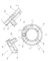
- FIG. 3 is a cross-sectional view of the air motor 100 as seen along a plane including the rotation center axis.
- the air motor 100 includes a housing 110, a front cover 120, a rear cover 130, a lens barrel 140, a runner 150, a front bearing 160, a rear bearing 170, a lens cap 180, and the like.
- the housing 110 is a casing that constitutes the outer peripheral surface portion of the air motor 100 and is formed in a cylindrical shape substantially concentric with the rotation shaft.
- FIG. 4 shows two surfaces of the housing 110.
- 4A is a partial cross-sectional side view of the housing 110 viewed from the radial direction
- FIG. 4B is a view taken along the line bb in FIG. 4A.
- the housing 110 is formed by integrally forming a cylindrical portion 111, a front cover flange 112, a front bearing holding portion 113, a runner accommodating portion 114, a swirl flow forming portion 115, a rear cover holding portion 116, and the like with a resin material. Yes.
- the cylindrical portion 111 is a portion that is formed in a cylindrical shape and constitutes the outer surface portion of the housing 110. Since the cylindrical part 111 positions each member accommodated in an axial direction, an outer diameter and an internal diameter expand sequentially in steps from the irradiation object side to the light source side (opposite side to the irradiation object side). It is formed as follows.
- the front cover flange 112 is a surface portion that protrudes from the inner peripheral surface in the vicinity of the irradiation object side end portion of the cylindrical portion 111 toward the inner diameter side.
- the front cover flange 112 is formed in a planar shape orthogonal to the central axis of the cylindrical portion 111 (the rotation axis of the air motor 100).
- a circular opening 112 a that is substantially concentric with the central axis of the cylindrical portion 111 is formed at the center of the front cover flange 112.
- the front cover flange 112 is formed with a screw hole portion 112b to which a screw used for fixing the front cover 120 is fastened.
- the front bearing holding portion 113 is a portion that holds the outer ring of the front bearing 160.
- the front bearing holding portion 113 is disposed adjacent to the light source side surface portion of the front cover flange 112.
- the front bearing holding portion 113 is formed to have an inner diameter that is enlarged stepwise with respect to the region closer to the irradiation object than this, and when the front bearing 160 is inserted from the light source side, the outer ring hits here. It is configured.
- the runner accommodating portion 114 and the swirl flow forming portion 115 are space portions that are sequentially arranged adjacent to the light source side of the front bearing holding portion 113.
- the runner accommodating portion 114 and the swirl flow forming portion 115 are formed to have substantially the same inner diameter, and are continuously provided in the direction of the rotation axis of the air motor.
- the runner accommodating portion 114 is a portion having a space for accommodating the blades 152 of the runner 150.
- the swirl flow forming unit 115 is a swirl flow swirling around the central axis of the air motor 100 by the air flow ejected from the air flow deflection nozzle 133 of the rear cover 130 (an air flow having a component along the circumferential direction of the swirl flow forming unit 115).
- the swirl flow forming portion 115 is disposed between the blades 152 of the runner 150 and the rear cover 130 in the direction of the rotation axis of the air motor 100. Between these, the cylindrical portion has a substantially constant outer diameter and inner diameter. It is formed to have. Further, the inner diameters of these portions are formed to be stepped larger than the inner diameter of the front bearing holding portion 113.
- the rear cover holding portion 116 is a portion that holds the outer peripheral edge portion of the rear cover 130.
- the rear cover holding part 116 is provided adjacent to the light source side of the swirl flow forming part 115 and has an inner diameter larger than that of the swirl flow forming part 115.
- the front cover 120 is a member that substantially closes the end of the cylindrical portion 111 of the housing 110 on the irradiation object side.
- FIG. 5 is a two-side view of the front cover. 5A is a view as seen from the irradiation object side, and FIG. 5B is a cross-sectional view taken along the line bb in FIG. 5A.
- the front cover 120 includes a disk part 121, a cylindrical part 122, and the like.
- the disk part 121 is formed as a disk-shaped flat plate concentric with the central axis of the air motor 100.
- the disk part 121 is inserted into the cylindrical part 111 of the housing 110 from the irradiation object side, and is fastened by screws with the outer peripheral edge part in contact with the front cover flange 112.
- a circular opening 121 a concentric with the central axis of the air motor 100 is formed at the center of the disk portion 121.
- the cylindrical part 122 is a cylindrical part that protrudes toward the lens cylinder 140 from the peripheral part of the opening 121 a of the disk part 121.
- the inner diameter of the cylindrical portion 122 is the smallest in the central portion in the axial direction, and is formed in a tapered shape so that the diameter gradually increases from here to the irradiation object side and the light source side.
- the rear cover 130 is a member that substantially closes the light source side end of the cylindrical portion 111 of the housing 110.
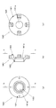
- FIG. 6 is a two-side view of the rear cover. 6A is a view from the light source side, and FIGS. 6B and 6C are cross-sectional views taken along the lines bb and cc of FIG. 6A, respectively. It is.
- FIG. 7 is an external perspective view of the rear cover as viewed from the inside of the air motor.
- the rear cover 130 includes a disk part 131, an air introduction pipe 132, an airflow deflection nozzle 133, and a rear bearing holding part 134.
- the disk part 131 is formed as a disk-shaped flat plate concentric with the central axis of the air motor 100.
- the disk portion 131 is a screw that is inserted into the cylindrical portion 111 of the housing 110 from the light source side and is inserted from the outer diameter side of the cylindrical portion 111 in a state where the outer peripheral edge abuts against the stepped portion of the rear cover holding portion 116.
- the fastening portion 131b is fixed by being fastened.
- a circular opening 131 a concentric with the central axis of the air motor 100 is formed at the center of the disk portion 131.
- the fastening portion 131b is formed so as to protrude from the surface portion on the light source side of the disc portion 131, and has a screw hole extending along the radial direction.
- the fastening portions 131b are arranged at substantially equal intervals, for example, at four locations in the circumferential direction of the disk portion 131.
- the air introduction pipe 132 is a part to which a hose that supplies compressed air from the compressor 60 to the air motor 100 is connected.
- the air introduction tube 132 is formed in a cylindrical shape, and is formed so as to protrude from the surface portion on the light source side of the disk portion 131 toward the light source side.
- the airflow deflection nozzle 133 changes the direction of the airflow introduced from the air introduction pipe 132 into the air motor 100 so as to flow in the circumferential direction along the inner peripheral surface of the cylindrical portion 111, and then the swirl flow forming portion 115. It is the flow path formed by being bent so as to be ejected into the inside.
- the airflow ejected from the airflow deflecting nozzle 133 flows along the inner peripheral surface of the cylindrical portion 111 inside the swirling flow forming portion 115, and thereby spirals flowing toward the runner 150 while swirling around the central axis of the air motor 100. It turns into a swirling flow and flows into the blades 152 of the runner 150.
- the rear bearing holding part 134 is a part that holds the outer ring of the rear bearing 170.
- the rear bearing holding part 134 is a cylindrical part formed so as to protrude from the inner peripheral edge of the opening 131 a of the disk part 131 to the inner side (irradiation target side) of the air motor 100.
- the outer ring of the rear bearing 170 is press-fitted and held on the inner diameter side of the rear bearing holding portion 134.
- the lens barrel 140 is a cylindrical member that houses the deflection optical system 33 of the laser irradiation unit 30 and a part of the lenses 32 a of the condensing optical system 32.
- the lens barrel 140 and the runner 150 constitute the main part of the rotor of the air motor 100 of the first embodiment.
- the lens barrel 140 and the runner 150 cooperate to rotate relative to the other part of the air motor 100 and the part other than the air motor 100 of the laser head H around the central axis thereof, and the polarization optical system 33 of the laser irradiation unit 30 is made to rotate. It is intended to rotate.
- the lens barrel 140 can be formed using, for example, an aluminum alloy having a high thermal conductivity in order to dissipate heat generated by the laser irradiation unit 30 to the outside. Moreover, when importance is attached to cost and weight reduction, you may form with a resin-type material.
- the lens barrel 140 is inserted into the housing 110 so as to be concentric with the rotation shaft of the air motor 100, and is supported by the front bearing 160 and the rear bearing 170 so as to be relatively rotatable with respect to the housing 110.
- a bearing holding portion 141 that holds the inner ring of the front bearing 160 is provided at the end of the lens barrel 140 on the irradiation object side.
- the bearing holding portion 141 is formed to project radially from the end of the lens tube 140 on the irradiation object side toward the outer diameter side.
- the bearing holding part 141 is in contact with the inner peripheral surface of the inner ring of the front bearing 160 and the end surface on the irradiation object side.
- a light source side end face of the inner ring of the front bearing 160 is held by a bearing collar 142.
- the bearing collar 142 is an annular member that is sandwiched between the end surface on the irradiation object side of the cylindrical portion 151 of the runner 150 and the bearing holding portion 141.
- the bearing collar 142 is appropriately provided with engagement means so as not to rotate relative to the lens tube 140 and the runner 150.
- the bearing holding portion 141 and the bearing collar 142 hold the front bearing 160 by a comb-like holding portion that protrudes radially outward and protrudes radially.
- the air flow W that flows out from the gap between the outer peripheral surface of the cylindrical portion 151 of the runner 150 and the inner peripheral portion of the annular portion 153 causes the bearing holding portion 141, the bearing collar to It is possible to pass through the interval between the comb teeth 142 from the inner diameter side of the front bearing 160 to the front cover 120 side.
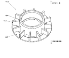
- the runner 150 is an impeller (turbine) that receives a swirling flow formed in the swirling flow forming portion 115 of the housing 110 and generates a driving force for rotationally driving the lens barrel 140.
- the runner 150 is integrally formed of, for example, a resin material.
- FIG. 8 is a two-side view of the runner. 8A is a view as seen from the irradiation object side, and FIG. 8B is a cross-sectional view taken along the line bb in FIG. 8A.
- the runner 150 includes a cylindrical portion 151, a blade 152, an annular portion 153, and the like.
- the cylindrical portion 151 is a portion into which the lens tube 140 is inserted.
- the cylindrical portion 151 is fixed to an intermediate portion in the axial direction on the outer peripheral surface portion of the lens tube 140.
- the blades 152 are formed so as to protrude from the outer peripheral surface of the cylindrical portion 151 toward the outer diameter side, and generate a rotational force by receiving a swirling flow.
- the blades 152 are formed in a rectangular flat plate shape substantially along a plane along the radial direction and the axial direction of the cylindrical portion 151.
- a plurality of blades 152 are provided in a distributed manner in the circumferential direction of the cylindrical portion 151, and are arranged radially when viewed from the rotation axis direction of the air motor 100.
- the end edge of the blade 152 on the rear cover 130 side is disposed to face the airflow deflection nozzle 133 of the rear cover 130 with an interval in the direction of the rotation axis of the air motor 100.
- the annular portion 153 is an annular member that interconnects the outer diameter side regions of the plurality of blades 152 at the end of the irradiation object side.
- the annular portion 153 is formed as a ring-shaped plate in which an opening concentric with the rotation shaft is formed at the center of a disk formed in a flat plate shape along a plane orthogonal to the rotation shaft of the air motor 100.
- the front bearing 160 and the rear bearing 170 are bearings that rotatably support the lens barrel 140 with respect to the housing 110.
- a rolling bearing such as a single row deep groove ball bearing can be used.
- the front bearing 160 holds the end of the lens barrel 140 on the irradiation object side.
- the inner ring of the front bearing 160 is held by the bearing holding portion 141 and the bearing collar 142 of the lens barrel 140 described above.
- the outer ring of the front bearing 160 is held by the front bearing holding portion 113 of the housing 110.
- the rear bearing 170 holds the end of the lens barrel 140 on the light source side.
- a lens tube 140 is inserted into the inner ring of the rear bearing 170.
- the inner peripheral surface of the inner ring of the rear bearing 170 is in contact with the outer peripheral surface of the lens tube 140.
- the end surface on the irradiation object side of the inner ring of the rear bearing 170 is in contact with the end surface on the light source side of the cylindrical portion 151 of the runner 150.
- the end surface on the light source side of the inner ring of the rear bearing 170 is held by a bearing cap 171 that is put on and fastened to an end portion on the light source side of the lens tube 140.
- An opening 171 a through which laser light passes is formed in the center of the bearing cap 171.
- the outer peripheral surface of the outer ring of the rear bearing 170 and the end surface on the light source side are held by the rear bearing holding portion 134 of the rear cover 130.
- the lens cap 180 is a ring-shaped member provided at the end of the lens barrel 140 on the irradiation object side for the purpose of protecting the optical system.
- FIG. 10 is a two-side view of the lens cap. Fig.10 (a) is the figure seen from the irradiation target object side.
- FIG. 10B is a cross-sectional view taken along the line bb in FIG.
- FIG. 10C is a view taken along the line cc of FIG. 10B.
- the lens cap 180 includes a disk portion 181, a cylindrical portion 182, an attachment portion 183, and the like.
- the disk portion 181 is formed in a flat plate shape along a plane orthogonal to the rotation axis of the air motor 100, and a circular opening 181a concentric with the rotation shaft is formed in the center portion.
- the cylindrical portion 182 is a cylindrical portion that is formed to protrude from the peripheral edge of the opening 181a in the disk portion 181 to the irradiation object side.
- the outer diameter of the cylindrical portion 182 gradually changes in a tapered shape so that the protruding end side becomes smaller. With such a configuration, as shown in FIG. 3, the outer peripheral surface of the cylindrical portion 182 and the inner peripheral surface of the cylindrical portion 122 of the front cover 120 are arranged to face each other with a small gap therebetween. It has become.
- the attachment portion 183 is a portion that becomes a base portion for fastening the lens cap 180 to the lens tube 140.
- the attachment portion 183 is formed to protrude from the vicinity of the outer peripheral edge of the disc portion 181 to the light source side, and is fastened to the end surface portion on the irradiation object side of the lens tube 140.
- four attachment portions 183 are provided at equal intervals in the circumferential direction of the disk portion 181. The space
- the laser irradiation apparatus 1 is used, for example, to peel a coating film on a surface of a structure such as a steel bridge installed outdoors, remove rust, and perform re-coating ground treatment.
- a structure such as a steel bridge installed outdoors
- the irradiation object, the type of treatment, and the use are not particularly limited.
- the laser irradiation device 1 is carried into the construction site, and power is connected to the laser oscillator 10, the dust suction device 50, and the compressor 60, respectively.
- the laser head H is held so that the focal point FP of the beam B substantially coincides with the surface of the irradiation object O, and compressed air is supplied from the compressor 60 to the air motor 100.
- the airflow W supplied to the air motor 100 is introduced into the air motor 100 from the air introduction pipe 132 of the rear cover 130 and is deflected by the airflow deflection nozzle 133 in a direction substantially along the tangential direction of the outer peripheral edge of the rear cover 130.
- a spiral swirl flow is formed in the swirl flow forming portion 115 along the inner peripheral surface of the cylindrical portion 111 and swirling clockwise as viewed from the rear cover 130 side. Is done.
- the swirling flow flows toward the runner accommodating portion 114, hits the blade 152 of the runner 150, and generates a rotational driving force for rotating the runner 150 and the lens tube 140 on the blade 152 by the pressure.
- the blade 152 is separated from the airflow deflection nozzle 133 in the axial direction, the jet flow from the airflow deflection nozzle 133 does not directly hit the blade 152. In this case, noise that may occur can be suppressed.
- the airflow W is generated between the annular portion 153 of the runner 150 and the cylindrical portion 151, between the bearing holding portion 141 of the lens barrel 140 and the comb teeth of the bearing collar 142, and The object to be irradiated passes through the end surface of the lens tube 140 and the disk portion 181 of the lens cap 180 (interval of the mounting portion 183) sequentially, and from the opening 181a of the disk portion 181 of the lens cap 180 and the cylindrical portion 182. Spout to the side. Further, a part of the airflow W is ejected to the irradiation object side through a gap between the outer peripheral surface of the cylindrical portion 182 of the lens cap 180 and the inner peripheral surface of the cylindrical portion 122 of the front cover 120.
- each of the optical elements (lens, wedge prism, etc.) of the laser irradiation unit 30 receives laser light
- a cooling gas flow path that is extracted and sprayed onto the optical element may be formed.
- the optical element can be cooled and protected, the component life can be extended, and the running cost of the apparatus can be reduced.
- a rotation sensor that detects the rotation speed of the rotor of the air motor 100 (the rotating portion of the lens barrel 140, the runner 150, etc.) is provided, and feedback control is performed so that the rotation speed of the air motor 100 approaches a predetermined target speed. Is desirable.
- the rotation speed of the air motor 100 can be controlled, for example, by adjusting the output of the compressor 60 to change the discharge amount and discharge pressure, or by adjusting the supply pressure to the air motor 100 using a pressure regulator. Further, the rotational speed of the air motor 100 may be controlled by mechanical control means such as a centrifugal governor.
- the rotation sensor does not detect (stops) the rotation of the air motor 100, or in an abnormal state where the rotation speed of the air motor 100 is outside a predetermined range, the irradiation object or the laser irradiation apparatus 1 itself is protected. Therefore, it is preferable to provide a safety device that stops the laser oscillator 10 to stop the irradiation.
- the laser oscillator 10 starts generating laser light, starts irradiation of the beam B from the laser head H to the irradiation object O, and the laser head. H is moved relative to the irradiation object O while maintaining a distance from the irradiation object O, and scanning of the irradiation object O is started.
- Such movement of the laser head H may be performed manually, for example, by an operator holding the laser head H.
- the movement of the laser head H may be performed automatically using a conveying means such as an XY stage or a robot arm. May be.
- the dust suction device 50 is operated, and the paint film fragments, rust, dust, smoke, and the like peeled off by the irradiation of the beam B are sucked and collected from the interval between the inner cylinder 41 and the outer cylinder 42 of the housing 40.
- the airflow (exhaust gas) after driving the runner 150 is ejected from the central part or the periphery of the lens cap 180 toward the irradiation object, so that the separated foreign matter is inside the air motor 100 or Inflow to the optical element side can be prevented. Further, by removing foreign matters in the optical path of the beam B, the energy reaching the irradiation target can be increased, and the processing capability can be improved.
- a laser irradiation apparatus that can drive the deflection optical system at a high speed of, for example, 10,000 rpm or more with a small and lightweight structure and can cope with the heat generation of the optical system. it can.
- Such an air motor 100 is lightweight because there is no need to provide a heavy magnetic body or coil unlike an electromagnetic motor, and the amount of heat generated by the air motor 100 itself is negligible. Further, even when the laser irradiation unit 30 generates heat and the inside of the housing 40 becomes high temperature, the performance can be ensured because the performance cannot be lowered due to the deterioration of the magnetic material.
- the air motor 100 can be cooled, and further, the exhaust of each laser irradiation unit 30 can be exhausted as necessary.
- the optical element When introduced into the optical element, the optical element can be cooled, and there is no need to provide a cooling device such as a water-cooling water jacket.
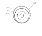
- FIG. 11 is a cross-sectional view of the laser irradiation apparatus according to the second embodiment.
- a laser irradiation unit 30 and an air motor 100 are accommodated in a housing 200 described below instead of the housing 40 of the first embodiment.
- the air motor 100 is substantially the same as the air motor 100 of the first embodiment except that the rear bearing 170 in the first embodiment is omitted for weight reduction and the rotating part is supported by a single bearing corresponding to the front bearing 160. It is configured.
- the housing 200 includes an inner cylinder 210, an outer cylinder 220, a front pipe 230, a collar 240, an inner duct 250, and the like.
- the inner cylinder 210 is formed in a substantially cylindrical shape and accommodates the laser irradiation unit 30 and the air motor 100 on the inner diameter side.
- An end of the inner cylinder 210 on the irradiation object side (left side in FIG. 11) is formed so as to protrude from the air motor 100 to the irradiation object side.
- the outer cylinder 220 is a portion that is substantially cylindrical and that accommodates the inner cylinder 210 on the inner diameter side. 12 is a schematic cross-sectional view taken along the line XII-XII in FIG.
- the inner diameter of the outer cylinder 220 is set larger than the outer diameter of the inner cylinder 210.
- the inner cylinder 210 is arranged eccentrically with respect to the outer cylinder 220 such that a part of the outer peripheral surface is in contact with the inner peripheral surface of the outer cylinder 220.
- the space between the outer peripheral surface of the inner cylinder 210 and the inner peripheral surface of the outer cylinder 220 is used for sucking floating substances such as coating film fragments, rust, and dust, as in the housing 40 of the first embodiment.
- the end of the outer cylinder 220 opposite to the irradiation object side is connected to the dust suction device via the suction hose 51.
- the end of the irradiation target of the outer cylinder 220 is disposed so as to protrude toward the irradiation target with respect to the end of the inner cylinder 210.
- the front pipe 230 is a cylindrical portion provided to project from the end of the outer cylinder 220 on the irradiation object side to the irradiation object side.
- the front pipe 230 is formed substantially concentrically with the outer cylinder 220 and has a tapered shape so that the irradiation object side has a small diameter.
- the collar 240 is an annular (short cylindrical) member that protrudes from the end of the front pipe 230 on the irradiation object side to the irradiation object.
- the collar 240 is disposed substantially concentrically with the front pipe 230.
- the inner duct 250 is a cylindrical member provided so as to protrude from the outer peripheral edge portion of the end surface on the irradiation object side of the air motor 100 toward the irradiation object side.
- 13 is a component diagram of the inner duct.
- FIG. 13 (a) is an enlarged view of the XIII portion of FIG. 11, and
- FIG. 13 (b) is a view taken along the line bb of FIG. 13 (a).
- FIG. 13 (a) is a cross-sectional view taken along the line aa in FIG. 13 (b).
- the inner duct 250 has a cylindrical shape substantially concentric with the inner cylinder 210, and is formed in a tapered shape so that the end on the irradiation object side has a smaller diameter than the end on the air motor 100 side. As shown in FIG. 11, the distance between the outer peripheral surface of the inner duct 250 and the inner peripheral surface of the inner cylinder 210 is set so as to increase toward the irradiation object side. The end of the inner duct 250 on the irradiation object side is disposed slightly offset from the end of the inner cylinder 210 toward the air motor 100.
- a stabilizer 251 is formed in the inner duct 250.
- the stabilizer 251 is a flat plate-shaped and rib-shaped rectifying fin formed to protrude from the inner peripheral surface of the inner duct 250 to the inner diameter side substantially along the radial direction.
- the stabilizer 251 extends along the central axis of the inner duct 250 (substantially concentric with the rotation central axis of the air motor 100).
- the protruding end portion (edge on the innermost diameter side) of the stabilizer 251 is formed so as to be substantially along a straight line, and when the beam B turns and passes closest to the stabilizer 251, It arrange
- the protrusion amount (rib height) of the stabilizer 251 from the inner peripheral surface of the inner duct 250 to the inner diameter side is set so as to continuously decrease from the air motor 100 side to the irradiation object side.
- the protruding amount of the stabilizer 251 is substantially zero, and the planar shape of the stabilizer 251 viewed from the circumferential direction of the inner duct 250 is substantially triangular. Has been.
- the exhaust of the air motor is prevented from forming a swirling flow along the inner peripheral surface of the inner duct 250, and the atmospheric pressure in the region near the axis is caused by such swirling flow. It is relatively low with respect to the outer peripheral side to prevent foreign matter from being sucked into the air motor 100 side, and contamination and deterioration of the lens and the like can be suppressed.
- the present invention is not limited to the embodiments described above, and various modifications and changes are possible, and these are also within the technical scope of the present invention.
- the structure, material, shape, quantity, arrangement, and the like of each member constituting the laser irradiation apparatus are not limited to the above-described embodiments, and can be changed as appropriate.
- air is used as a gas for driving the air motor.
- an incombustible gas such as nitrogen or carbon dioxide, an inert gas such as helium, neon, or argon; Other gases such as reactive gases that facilitate film removal may be used.
- the application of the laser irradiation device is not limited to coating film removal and repainting ground treatment as in the embodiment, but for example, grounding treatment during open inspection of large tanks, pre-welding treatment for large machine equipment, etc. It can also be used for surface modification, removal of dirt or rust on harbor facilities, and the like. Also, dirt, graffiti, etc. adhering to the concrete surface can be removed. Furthermore, it can be used to remove paint and deposits contaminated by radioactivity.
- the laser head housing has a double-cylinder structure that irradiates the laser from the inner cylinder and ejects air, and sucks floating matter from the outer cylinder. Is not limited to this.
- tip part of an inner cylinder and an outer cylinder is not specifically limited.
- a sliding assist means may be provided.
- sliding assisting means for example, rolling elements such as tires and rollers, and brush-like or curtain-like members formed of a flexible material can be used.
- the hollow type using a swirl flow is used as an air motor in the embodiment, the type of the air motor is not particularly limited.
- an air motor such as a vane type may be used.
- the compressor is used as the gas supply source in the embodiment, the present invention is not limited thereto, and a blower or a cylinder may be used.
- the air motor 100 is detachable from the laser head H for exchanging the deflection optical system 33.
- the air motor 100 is not limited to detaching the entire air motor 100. Only the lens barrel 140 and the runner 150 may be detachable. Furthermore, for example, only a part of the lens barrel 140 where the polarization optical system 33 is provided may be detachable.
- O irradiation object (processing object) H laser head B beam FP focus 10 laser oscillator 20 fiber 30 laser irradiation unit 31 fiber connection part 32 condensing optical system 32a lens 33 deflection optical system 40 housing 41 inner cylinder 42 outer cylinder 50 dust absorption Device 51 Suction hose 60 Compressor 61 Supply hose 100 Air motor 110 Housing 111 Cylindrical part 112 Front cover flange 112a Opening 113 Front bearing holding part 114 Runner housing part 115 Swirling flow forming part 116 Rear cover holding part 120 Front cover 121 Disk part 121a Opening 122 Tubular part 130 Rear cover 131 Disc part 131a Open 131b Fastening portion 132 Air introduction pipe 133 Airflow deflection nozzle 134 Rear bearing holding portion 140 Lens tube 141 Bearing holding portion 142 Bearing collar 150 Runner 151 Cylindrical portion 152 Blade 153 Ring portion 160 Front bearing 170 Rear bearing 171 Bearing cap 171a Opening 180 Lens cap 181 Disc part 181a Opening 182 Cylind
Abstract
Description
このような塗装の剥離は、従来サンドブラスト、塗装剥離剤、機械工具(サンダー)等を利用することが一般的であったが、近年、構造物の表面にレーザ光を照射し、塗膜を破砕して剥離、除去することが提案されている。
このような偏向光学系は、例えばモータの回転中心軸周辺が空洞とされたいわゆる中空モータの内径側に収容することによって、レーザヘッドをコンパクトに構成することが可能である。
しかし、走査性能を向上して処理能力を改善するため、偏向光学系を例えば10000rpm以上の高速で駆動する場合、電力によってモータを駆動させる電磁モータで十分な出力、トルクを確保するためには大径のものが必要となり、レーザヘッドが大型化して重量も増加してしまう。
また、このようなレーザヘッドにおいては、電磁モータ自体の発熱に加え、レンズ、プリズム等の光学素子がレーザ光を受けて発熱する場合があり、電磁モータの場合には磁性体の高温劣化(高温減磁)による性能低下が生じてしまう。
上述した問題に鑑み、本発明の課題は、小型軽量な構造によって偏向光学系を高速で駆動することができかつ光学系の発熱に対処可能なレーザ照射装置を提供することである。
請求項1に係る発明は、レーザ発振器が発生するレーザ光を所定の焦点に集光させる集光光学系と、前記集光光学系から出たレーザ光を所定の偏角だけ偏向させる偏向光学系と、前記偏向光学系を前記集光光学系の光軸と実質的に平行に配置された回転軸周りに回転駆動する駆動手段とを備えるレーザ照射装置であって、前記駆動手段は、気体供給源から供給される気体が有するエネルギを回転力に変換するエアモータを有することを特徴とするレーザ照射装置である。
なお、本明細書及び請求の範囲の記載において、「エアモータ」とは、気体を作動流体として回転出力を発生する圧力モータ(気体供給源から供給される気体が有するエネルギを回転力に変換する機械)全般を指すものとする。
これによれば、偏向光学系の駆動にエアモータ(エアタービン)を用いることによって、駆動手段を小型かつ軽量とすることができ、装置をコンパクトに構成することが可能となる。
また、電磁モータのように磁性体を用いる必要がないことから、光学素子等が発する熱によって加熱された場合であっても減磁による性能劣化が生じ得ない。
これによれば、エアモータを旋回流によって駆動される円環状の中空モータとし、中央部にレーザ光の光路を配置することによって、装置をよりいっそうコンパクトに構成することができる。
これによれば、光学素子の少なくとも一部をロータの内径側に収容することによって、装置をさらにコンパクトに構成することができる。
これによれば、レーザ照射時に焼損等によって消耗しやすい偏向光学系をエアモータとともに脱着可能とすることによって、交換作業を容易に行うことが可能となる。
これによれば、周方向に分散する複数の羽根に均等に旋回流を作用させることが可能となり、騒音を抑制することができる。
これによれば、エアモータの排気を偏向光学系よりも照射対象物側へ排出することによって、レーザ照射により照射対象物から剥離した浮遊物が偏向光学系側に流れて付着することを防止できる。
また、レーザ光の光路から浮遊物を排除することによって、照射対象物に到達するエネルギを高め、処理能力を向上することができる。
これによれば、エアモータの排気を利用して簡単な構成により効果的に光学素子を冷却することが可能となり、光学素子の焼損や劣化を防止することができる。
これによれば、除去物が周囲に浮遊して環境を汚染したり、装置の内部に侵入して光学素子に付着すること等を防止できる。
これによれば、エアモータが停止している場合のように正常に回転していない場合にレーザ光を照射し、照射対象物の一部に連続的に高エネルギが供給され、焼損や溶損等のダメージが発生することを防止できる。
これによれば、レーザ光が照射対象物を走査する速度を適切に維持し、良好な処理性能を得ることができる。
これによれば、ダクトの内周面に沿ってエアモータの排気が旋回流を形成する結果、軸心近傍の領域の気圧が外周側に対して相対的に低くなり、光学系側へ異物が吸引されることを防止し、光学系の汚れや劣化を抑制することができる。
請求項12に係る発明は、前記ダクトは筒状に形成された外筒の内径側に挿入され、前記レーザ光が照射対象物に照射された際に生じる除去物を前記ダクトの外周面と前記外筒の内周面との間隔から吸引する吸引手段を備えることを特徴とする請求項11に記載のレーザ照射装置である。
これによれば、ダクトの外径側に設けられる外筒によって除去物を吸引することによって、上述した効果をより向上することができる。
実施例1のレーザ照射装置及び表面処理方法は、例えば、鋼製の橋梁の塗装剥離処理等に好適なものであるが、処理対象物はこれに限定されない。
レーザ照射装置1は、レーザ発振器10、ファイバ20、レーザ照射ユニット30、ハウジング40、吸塵装置50、コンプレッサ60、エアモータ100等を有して構成されている。
レーザ照射ユニット30、ハウジング40、及び、エアモータ100は、作業者の手やロボットアーム等の搬送装置によって保持され、レーザ光からなるビームBを照射しつつ照射対象物に対して相対移動することによって、被照射面を走査するレーザヘッドHを構成する。
レーザ発振器10は、連続発振(CW)型及びパルス発振型の何れでもよく、例えばアークランプ、フラッシュランプなどを使用することができる。
また、使用する光源に応じて励起電流などを加えて駆動するための駆動手段を備えてもよい。
レーザ媒質は、固体レーザ(ルビーレーザ、YAGレーザ等)や半導体レーザ(レーザダイオード)を採用することが好ましい。
特に固体レーザとして、ファイバーレーザを使用することが好ましい。
なお、レーザ媒質は特に限定されるものではなく、そのほか、気体レーザ(CO2レーザ、エキシマレーザ等)、液体レーザ(色素レーザ)などを利用してもよい。
ファイバ20は、コアの周囲をクラッドで被覆した光ファイバの周囲に、補強用、保護用の被覆を形成して構成されている。
ファイバ20は、レーザヘッドHによる照射対象物の走査を妨げないよう可撓性を有している。
ファイバ接続部31は、ファイバ20のレーザヘッドH側の端部が接続され、伝達されてきたレーザ光を集光光学系32に案内するものである。
ファイバ接続部31には、ファイバ20から入射されるレーザ光を平行光線とするコリメート光学系が設けられている。
集光光学系32は、例えば複数枚のレンズを有して構成されており、その一部は後述する偏向光学系33と共通の支持部材(レンズ筒140)によって支持され、偏向光学系33とともにエアモータ100によって回転駆動される。
偏向光学系33は、例えば、ウェッジプリズムを有して構成されている。
偏向光学系33は、駆動用動力源であるエアモータ100によって、集光光学系32の光軸と実質的に平行に配置された回転軸回りに、所定の回転速度で回転駆動される。
ハウジング40は、例えば、樹脂系材料をインジェクション成型することによって形成されている。
ハウジング40は、内筒41及び外筒42を有して形成されている。
レーザ照射ユニット30及びエアモータ100は、内筒41の内径側に収容されている。
内筒41の照射対象物側の端部は開口しており、ビームBはこの開口を通過して照射対象物に照射される。
内筒41は、外筒42の内径側に挿入され、内筒41の外周面と外筒42の内周面とは、所定の間隔を隔てて対向して配置されている。
外筒42の周面部における照射対象物側の端部近傍には、レーザヘッドHが吸塵装置50の吸引力によって照射対象物に吸着してしまうことを防止するため、図示しない開口(貫通穴)が適宜形成される。
外筒42の照射対象物側の端部は開口しており、ビームBの照射によって照射対象物から剥離した、例えば塗膜の破片、錆、ダストなどの浮遊物は、内筒41と外筒42との隙間から吸引され回収される。
吸塵装置50は、例えば、遠心式ターボ送風機等の気体吸引手段、吸引された物体を処理する処理室、フィルタ等を有して構成されている。
コンプレッサ60として、例えば、容積式のものを用いることができる。
また、コンプレッサ60からエアモータ100に圧縮空気を供給する管路に、供給圧力を調節する図示しないプレッシャーレギュレータを設けてもよい。
エアモータ100は、回転中心軸を含む中央部が空洞とされた、円環状の渦流式中空モータである。
エアモータ100は、偏向光学系33の焼損時における交換を容易とするため、レーザ照射ユニット30の偏向光学系33を保持した状態で、レーザヘッドHの他部から着脱可能となっている。
エアモータ100の構成及び動作については、後に詳しく説明する。
上述した構成によって、レーザ照射ユニット30から射出されるビームBは、集光光学系32の光軸が通過する偏向光学系33の中央部を頂点とし、偏向光学系33の偏角を半頂角とする円錐の側面に沿って、周方向に旋回する挙動を示す。
このとき、ビームBの焦点FPは、集光光学系32の光軸を中心とし、この光軸と直交する平面に沿った円周上を旋回することになる。
レーザヘッドHを処理対象面に対して、集光光学系32の光軸が照射対象物Oの処理対称面(被照射面)と直交し、かつ焦点FPが処理対象面上となるように保持すると、ビームBの焦点FPは、円周上を旋回しながら処理対象面を走査する。
このような構成とすることによって、CWレーザを用いた場合であっても、同一箇所に連続的にレーザ光が照射されることを防止できる。
なお、焦点FPにおけるビーム径、被照射面上における旋回半径、旋回速度、レーザヘッドHの走査速度等は、照射対象物の特性や必要とされる処理の種類に応じて適宜設定される。
図3は、エアモータ100を、回転中心軸を含む平面で切って見た断面図である。
エアモータ100は、ハウジング110、フロントカバー120、リアカバー130、レンズ筒140、ランナ150、フロントベアリング160、リアベアリング170、レンズキャップ180等を有して構成されている。
図4は、ハウジング110の二面部である。
図4(a)は、ハウジング110を径方向から見た部分断面側面図であり、図4(b)は図4(a)のb-b部矢視図である。
ハウジング110は、筒状部111、フロントカバーフランジ112、フロントベアリング保持部113、ランナ収容部114、旋回流形成部115、リアカバー保持部116等を、樹脂系材料によって一体に形成して構成されている。
筒状部111は、内部に収容される各部材を軸方向に位置決めするため、照射対象物側から光源側(照射対象物側と反対側)にかけて、段階的に外径及び内径が順次拡大するように形成されている。
フロントカバーフランジ112は、筒状部111の中心軸(エアモータ100の回転軸)と直交する平面状に形成されている。
フロントカバーフランジ112の中央部には、筒状部111の中心軸と実質的に同心の円形の開口112aが形成されている。
フロントカバーフランジ112には、フロントカバー120の固定に用いられるビスが締結されるネジ穴部112bが形成されている。
フロントベアリング保持部113は、フロントカバーフランジ112の光源側の面部に隣接して配置されている。
フロントベアリング保持部113は、これよりも照射対象物側の領域に対して段状に内径を拡大して形成されており、フロントベアリング160を光源側から挿入した際に、外輪がここで突き当たるように構成されている。
ランナ収容部114、旋回流形成部115は、実質的に同一の内径に形成され、エアモータの回転軸方向に連続して設けられている。
ランナ収容部114は、ランナ150の羽根152を収容する空間を有する部分である。
旋回流形成部115は、リアカバー130の気流偏向ノズル133から噴出した空気流によって、エアモータ100の中心軸回りに旋回する旋回流(流速が旋回流形成部115の周方向に沿った成分を有する気流)が形成される空間を有する部分である。
旋回流形成部115は、エアモータ100の回転軸方向において、ランナ150の羽根152とリアカバー130との間に配置され、これらの間においては、筒状部は実質的に一定の外径、内径を有するよう形成されている。
また、これらの部分の内径は、フロントベアリング保持部113の内径よりも段状に大きく形成されている。
リアカバー保持部116は、旋回流形成部115の光源側に隣接して設けられ、旋回流形成部115よりも内径が段状に大きく形成されている。
図5は、フロントカバーの二面図である。
図5(a)は照射対象物側から見た図であり、図5(b)は図5(a)のb-b部矢視断面図である。
フロントカバー120は、円盤部121、筒状部122等を有して構成されている。
円盤部121は、ハウジング110の筒状部111に照射対象物側から挿入され、外周縁部がフロントカバーフランジ112に当接した状態で、ビスによって締結される。
円盤部121の中央部には、エアモータ100の中心軸と同心の円形の開口121aが形成されている。
筒状部122の内径は、軸方向における中央部が最も小さくなっており、ここから照射対象物側及び光源側にかけて徐々に径が大きくなるようテーパ状に形成されている。
図6は、リアカバーの二面図である。
図6(a)は、光源側から見た図であり、図6(b)及び図6(c)は、それぞれ図6(a)のb-b部及びc-c部の矢視断面図である。
図7は、リアカバーをエアモータ内部側から見た外観斜視図である。
円盤部131は、ハウジング110の筒状部111に光源側から挿入され、外周縁部がリアカバー保持部116の段部に突き当たった状態で、筒状部111の外径側から挿入されるビスで、締結部131bを締結されることによって固定されている。
円盤部131の中央部には、エアモータ100の中心軸と同心の円形の開口131aが形成されている。
締結部131bは、円盤部131の光源側の面部から張り出して形成され、径方向に沿って延在するネジ穴が形成されている。
締結部131bは、例えば、円盤部131の周方向における4箇所に実質的に等間隔に配列されている。
空気導入管132は、円筒状に形成され、円盤部131の光源側の面部から光源側へ突出して形成されている。
気流偏向ノズル133から噴出した気流は、旋回流形成部115の内部において、筒状部111の内周面に沿って流れることによって、エアモータ100の中心軸回りに旋回しつつランナ150側へ流れる螺旋状の旋回流となり、ランナ150の羽根152に流入する。
リアベアリング保持部134は、円盤部131の開口131aの内周縁部から、エアモータ100の内部側(照射対象物側)に突き出して形成された円筒状の部分である。
リアベアリング170の外輪は、リアベアリング保持部134の内径側に圧入され保持される。
レンズ筒140及びランナ150は、実施例1のエアモータ100のロータの主要部を構成する。レンズ筒140及びランナ150は、共働してエアモータ100の他部及び、レーザヘッドHのエアモータ100以外の部分に対してその中心軸回りに相対回転し、レーザ照射ユニット30の偏光光学系33を回転させるものである。
レンズ筒140は、例えば、レーザ照射ユニット30が発生する熱を外部に放熱するため、熱伝導率が高いアルミニウム系合金などを用いて形成することができる。
また、コスト及び軽量化が重視される場合には樹脂系材料によって形成してもよい。
レンズ筒140は、エアモータ100の回転軸と同心となるようにハウジング110の内部に挿入され、フロントベアリング160、リアベアリング170によって、ハウジング110に対して相対回転可能に支持される。
ベアリング保持部141は、レンズ筒140の照射対象物側の端部から外径側へ放射状に突出して形成されている。
ベアリング保持部141は、フロントベアリング160の内輪における内周面及び照射対象物側の端面と当接するものである。
ベアリングカラー142は、ランナ150の筒状部151の照射対象物側の端面と、ベアリング保持部141との間に挟持される円環状の部材である。
ベアリングカラー142は、レンズ筒140及びランナ150に対して相対回転しないよう係合手段が適宜設けられている。
このような構成によって、図3に示すように、ランナ150の筒状部151の外周面と円環部153の内周縁部との隙間から流出した空気流Wは、ベアリング保持部141、ベアリングカラー142の櫛歯の間隔を通って、フロントベアリング160の内径側からフロントカバー120側へ通過することが可能となっている。
ランナ150は、例えば、樹脂系材料によって一体に形成されている。
図8は、ランナの二面図である。
図8(a)は、照射対象物側から見た図であり、図8(b)は、図8(a)のb-b部矢視断面図である。
ランナ150は、円筒部151、羽根152、円環部153等を有して構成されている。
円筒部151は、レンズ筒140の外周面部における軸方向中間部に固定される。
羽根152は、円筒部151の径方向及び軸方向に沿った平面に実質的に沿った矩形の平板状に形成されている。
羽根152は、円筒部151の周方向に分散して複数設けられ、エアモータ100の回転軸方向から見たときに、放射状に配置されている。
図3に示すように、羽根152のリアカバー130側の端縁は、リアカバー130の気流偏向ノズル133に対して、エアモータ100の回転軸方向に間隔を隔てて対向して配置されている。
円環部153は、エアモータ100の回転軸と直交する平面に沿った平板状に形成された円盤の中央部に、回転軸と同心の開口を形成したリング状のプレートとして形成されている。
フロントベアリング160、リアベアリング170として、例えば単列の深溝玉軸受等の転がり軸受を用いることができる。
フロントベアリング160の内輪は、上述したレンズ筒140のベアリング保持部141及びベアリングカラー142によって保持されている。
フロントベアリング160の外輪は、ハウジング110のフロントベアリング保持部113に保持されている。
リアベアリング170の内輪には、レンズ筒140が挿入されている。
リアベアリング170の内輪の内周面は、レンズ筒140の外周面と当接している。
リアベアリング170の内輪の照射対象物側の端面は、ランナ150の筒状部151の光源側の端面と当接している。
リアベアリング170の内輪の光源側の端面は、レンズ筒140の光源側の端部に被せられ締結されるベアリングキャップ171によって保持されている。
ベアリングキャップ171の中央部には、レーザ光が通過する開口171aが形成されている。
リアベアリング170の外輪の外周面及び光源側の端面は、リアカバー130のリアベアリング保持部134に保持されている。
図10は、レンズキャップの二面図である。
図10(a)は、照射対象物側から見た図である。図10(b)は、図10(a)のb-b部矢視断面図である。図10(c)は、図10(b)のc-c部矢視図である。
レンズキャップ180は、円盤部181、筒状部182、取付部183等を有して構成されている。
筒状部182は、円盤部181における開口181aの周縁部から、照射対象物側へ突出して形成された円筒状の部分である。
筒状部182の外径は、突端部側が小さくなるようテーパ状に徐変するようになっている。
このような構成によって、図3に示すように、筒状部182の外周面とフロントカバー120の筒状部122の内周面とは、微小な間隔を隔てて対向して配置されるようになっている。
取付部183は、レンズキャップ180をレンズ筒140に締結する基部となる部分である。
取付部183は、円盤部181の外周縁部近傍から光源側へ突き出して形成され、レンズ筒140の照射対象物側の端面部に締結される。
取付部183は、円盤部181の周方向に等間隔に例えば4箇所設けられている。
各取付部183の間隔は、気流Wが通過可能となっている。
実施例1のレーザ照射装置1は、例えば、屋外に設置される鋼製の橋梁等の構造物表面の塗装被膜を剥離するとともに、錆等を除去し、再塗装の下地処理を行うために用いられるが、照射対象物、処理の種類、用途は特に限定されない。
先ずレーザ照射装置1を施工現場に搬入し、レーザ発振器10、吸塵装置50、コンプレッサ60にそれぞれ電源を接続する。
エアモータ100に供給された気流Wは、リアカバー130の空気導入管132からエアモータ100の内部へ導入され、気流偏向ノズル133によってリアカバー130の外周縁部の接線方向に実質的に沿った方向に偏向されてハウジング110の旋回流形成部115の内部に噴出される。
これによって、旋回流形成部115の内部には、筒状部111の内周面に沿って、リアカバー130側から見て時計回り方向に旋回しつつランナ150側へ流れる螺旋状の旋回流が形成される。
このとき、羽根152を気流偏向ノズル133に対して軸方向に離間させた構成としたことによって、羽根152に気流偏向ノズル133から出た噴流が直接当たることがないため、仮にそのような構成とした場合に発生し得る騒音を抑制できる。
また、一部の気流Wは、レンズキャップ180の筒状部182の外周面と、フロントカバー120の筒状部122の内周面との間の隙間を通って照射対象物側へ噴出する。
これによって、光学素子を冷却保護し、部品寿命を長くして装置のランニングコストを低下させることができる。
エアモータ100の回転速度は、例えば、コンプレッサ60の出力を調節して吐出量、吐出圧力を変化させたり、圧力レギュレータを用いてエアモータ100への供給圧力を調節することによって制御できる。
また、例えば遠心ガバナ等の機械的な制御手段によってエアモータ100の回転速度を制御するようにしてもよい。
このようなレーザヘッドHの移動は、例えば作業者がレーザヘッドHを把持して手作業によって行ってもよいが、例えばXYステージやロボットアーム等の搬送手段を用いて自動的に行われるようにしてもよい。
なお、エアモータ100の回転中は、ランナ150を駆動した後の気流(排気)がレンズキャップ180の中央部又は周囲から、照射対象物側に噴出するため、剥離した異物がエアモータ100の内部や各光学素子側に流入することを防止できる。
また、ビームBの光路内の異物を排除することによって、照射対象物に到達するエネルギを増やし、処理能力を向上することができる。
このようなエアモータ100は、電磁モータのように重量の嵩む磁性体やコイルを設ける必要がないため軽量であり、さらに、エアモータ100自体が発生する熱量も無視し得る程度のものである。また、レーザ照射ユニット30が発熱してハウジング40内が高温となった場合であっても、磁性体の劣化等による性能低下が生じ得ないため、性能を確保できる。
実施例と実質的に同様の箇所には同じ符号を付して説明を省略し、主に相違点について説明する。
図11は、実施例2のレーザ照射装置の断面図である。
実施例2のレーザ照射装置は、実施例1のハウジング40に代えて、以下説明するハウジング200の内部にレーザ照射ユニット30及びエアモータ100を収容したものである。
エアモータ100は、軽量化のため実施例1におけるリアベアリング170を省略し、フロントベアリング160に相当する単一のベアリングによって回転部分が支持される以外は、実施例1のエアモータ100と実質的に同様に構成されている。
内筒210は、実質的に円筒状に形成され、レーザ照射ユニット30及びエアモータ100を内径側に収容する部分である。
内筒210の照射対象物側(図11における左側)の端部は、エアモータ100よりも照射対象物側に張り出して形成されている。
図12は、図11のXII-XII部模式的矢視断面図である。
外筒220の内径は、内筒210の外径に対して大きく設定されている。
内筒210は、外周面における一部が外筒220の内周面に接するよう、外筒220に対して偏心して配置されている。
内筒210の外周面と外筒220の内周面との間の空間部は、実施例1のハウジング40と同様に、塗膜の破片、錆、ダストなどの浮遊物の吸引に用いられる。
外筒220の照射対象物側とは反対側の端部は、吸引ホース51を介して吸塵装置に接続されている。
外筒220の照射対象物の端部は、内筒210の端部に対して照射対象物側に張り出して配置されている。
フロントパイプ230は、外筒220と実質的に同心に形成され、照射対象物側が小径となるようにテーパ状に形成されている。
カラー240は、フロントパイプ230と実質的に同心に配置されている。
図13は、インナダクトの部品図であって、図13(a)は図11のXIII部拡大図であり、図13(b)は図13(a)のb-b部矢視図である。なお、図13(a)は、図13(b)のa-a部矢視断面図である。
インナダクト250は、内筒210と実質的に同心の筒状であって、照射対象物側の端部がエアモータ100側の端部に対して小径となるようにテーパ状に形成されている。
図11に示すように、インナダクト250の外周面と内筒210の内周面との間隔は、照射対象物側にいくほど拡大するように設定されている。
インナダクト250の照射対象物側の端部は、内筒210の端部よりもややエアモータ100側にオフセットして配置されている。
スタビライザ251は、インナダクト250の内周面から、実質的に径方向に沿って内径側に突出して形成された平板状かつリブ状の整流フィンである。
スタビライザ251は、インナダクト250の中心軸(エアモータ100の回転中心軸と実質的に同心)に沿って延在している。
スタビライザ251の突端部(最も内径側の縁部)は、実質的に直線に沿うように形成され、ビームBが旋回してスタビライザ251に最も隣接して通過する際に、このビームBと微小な間隔を隔てて対向するよう配置されている。
インナダクト250の内周面から内径側へのスタビライザ251の突出量(リブ高さ)は、エアモータ100側から照射対象物側へかけて連続的に減少するよう設定されている。
インナダクト250の照射対象物側の端部においては、スタビライザ251の突出量は実質的にゼロとなっており、スタビライザ251をインナダクト250の周方向から見た平面形状は、実質的に三角形状に形成されている。
本発明は、以上説明した実施例に限定されることなく、種々の変形や変更が可能であって、それらも本発明の技術的範囲内である。
(1)レーザ照射装置を構成する各部材の構造、材質、形状、数量、配置等は、上述した実施例に限らず、適宜変更することが可能である。
(2)実施例においては、エアモータを駆動する気体として空気を利用しているが、これに限らず、例えば窒素や二酸化炭素等の不燃性ガス、ヘリウム、ネオン、アルゴン等の不活性ガス、塗膜除去を促進する反応性ガスなどの他の気体を用いてもよい。
(3)レーザ照射装置の用途は、実施例のような塗膜除去、再塗装用の下地処理に限らず、例えば大型タンクの開放検査時の下地処理、大型機械設備等の溶接前処理などの表面改質処理、港湾部設備などの汚れ又は錆の除去などにも利用可能である。
また、コンクリート表面に付着した汚れ、落書き等も除去することができる。さらに、放射能に汚染された塗料や付着物の除去にも利用可能である。
(4)実施例ではレーザヘッドのハウジングを二重筒構造とし、内筒からレーザを照射しかつ空気を噴出させるとともに、外筒から浮遊物を吸引する構成としているが、ハウジングや吸塵機構の構成はこれに限定されない。
また、二重筒構造とした場合、内筒、外筒の先端部の位置関係(内筒、外筒の一方が他方に対して照射対象物側に突出する等)も特に限定されない。
また、レーザヘッドを照射対象物と所定の間隔を隔てて移動させることを補助するため、摺動補助手段を設けてもよい。このような摺動補助手段として、例えば、タイヤ、ローラ等の転動体や、可撓性を有する材料によって形成された刷毛状、カーテン状等の部材を用いることができる。
(5)実施例ではエアモータとして旋回流を利用した中空形のものを利用しているが、エアモータの形式は特に限定されない。例えば、ベーン式等のエアモータを用いてもよい。
(6)実施例では気体供給源としてコンプレッサを用いているが、これに限らず送風機やボンベを用いてもよい。
(7)実施例では、偏向光学系33の交換のため、エアモータ100をレーザヘッドHから着脱可能としているが、エアモータ100全体を着脱することに限らず、例えば、エアモータ100から回転部分であるロータ(レンズ筒140、ランナ150等)のみを着脱可能としてもよい。さらに、例えばレンズ筒140から偏光光学系33が設けられる一部のみを着脱可能としてもよい。
B ビーム FP 焦点
10 レーザ発振器 20 ファイバ
30 レーザ照射ユニット 31 ファイバ接続部
32 集光光学系 32a レンズ
33 偏向光学系 40 ハウジング
41 内筒 42 外筒
50 吸塵装置 51 吸引ホース
60 コンプレッサ 61 供給ホース
100 エアモータ
110 ハウジング 111 筒状部
112 フロントカバーフランジ 112a 開口
113 フロントベアリング保持部 114 ランナ収容部
115 旋回流形成部 116 リアカバー保持部
120 フロントカバー 121 円盤部
121a 開口 122 筒状部
130 リアカバー 131 円盤部
131a 開口 131b 締結部
132 空気導入管 133 気流偏向ノズル
134 リアベアリング保持部
140 レンズ筒 141 ベアリング保持部
142 ベアリングカラー
150 ランナ 151 筒状部
152 羽根 153 円環部
160 フロントベアリング
170 リアベアリング 171 ベアリングキャップ
171a 開口
180 レンズキャップ 181 円盤部
181a 開口 182 筒状部
183 取付部
200 ハウジング(実施例2) 210 内筒
220 外筒 230 フロントパイプ
240 カラー 250 インナダクト
251 スタビライザ
Claims (12)
- レーザ発振器が発生するレーザ光を所定の焦点に集光させる集光光学系と、
前記集光光学系から出たレーザ光を所定の偏角だけ偏向させる偏向光学系と、
前記偏向光学系を前記集光光学系の光軸と実質的に平行に配置された回転軸周りに回転駆動する駆動手段と
を備えるレーザ照射装置であって、
前記駆動手段は、気体供給源から供給される気体が有するエネルギを回転力に変換するエアモータを有すること
を特徴とするレーザ照射装置。 - 前記エアモータは、前記気体供給源から供給される気体によって前記回転軸周りに旋回する旋回流を形成する旋回流形成部と、
前記旋回流によって回転駆動されるロータとを有し、
前記旋回流形成部及び前記ロータは前記回転中心軸を含む中央部が中空とされ、前記レーザ光は前記旋回流形成部及び前記ロータの中央部を通過すること
を特徴とする請求項1のレーザ照射装置。 - 中空に形成された前記ロータの内径側に前記偏向光学系の少なくとも一部の光学素子が設けられること
を特徴とする請求項2に記載のレーザ照射装置。 - 前記エアモータ及び前記偏向光学系の少なくとも一部が一体のユニットとして他部から着脱可能であること
を特徴とする請求項3に記載のレーザ照射装置。 - 前記ロータは放射状に配置され前記旋回流を受けて回転力を発生させる複数の羽根を有し、
前記羽根は、前記旋回流形成部と前記回転軸方向に離間して配置されること
を特徴とする請求項2から請求項4までのいずれか1項に記載のレーザ照射装置。 - 前記エアモータは、前記レーザ光が通過する光路を含みかつ前記偏向光学系よりも照射対象物側の空間部内に排気を排出すること
を特徴とする請求項2から請求項5までのいずれか1項に記載のレーザ照射装置。 - 前記エアモータの排気を前記偏向光学系と前記集光光学系の少なくとも一方に含まれる光学素子に誘導する導風手段を有すること
を特徴とする請求項1から請求項6までのいずれか1項に記載のレーザ照射装置。 - 前記レーザ光が照射対象物に照射された際に生じる除去物を吸引する吸引手段を備えること
を特徴とする請求項1から請求項7までのいずれか1項に記載のレーザ照射装置。 - 前記エアモータの回転速度を検出する回転速度センサと、
前記回転速度が所定の正常範囲以外である場合に前記レーザ光の照射を禁止する照射禁止手段と
を備えることを特徴とする請求項1から請求項8までのいずれか1項に記載のレーザ照射装置。 - 前記エアモータの回転速度を検出する回転速度センサと、
前記回転速度が予め設定された目標回転速度に近づくよう前記気体供給源をフィードバック制御する制御手段と
を備えることを特徴とする請求項1から請求項9までのいずれか1項に記載のレーザ照射装置。 - 前記偏向光学系に対して照射対象物側に突き出して筒状に形成され、前記偏向光学系から出たレーザ光が内径側を通過するとともに、前記エアモータの排気が導入されるダクトを有し、
前記ダクトの内周面から内径側に突出しかつ前記ダクトの中心軸方向に沿って延在するスタビライザを前記ダクトの周方向に沿って複数形成したこと
を特徴とする請求項1から請求項7、請求項9,10のいずれか1項に記載のレーザ照射装置。 - 前記ダクトは筒状に形成された外筒の内径側に挿入され、
前記レーザ光が照射対象物に照射された際に生じる除去物を前記ダクトの外周面と前記外筒の内周面との間隔から吸引する吸引手段を備えること
を特徴とする請求項11に記載のレーザ照射装置。
Priority Applications (3)
| Application Number | Priority Date | Filing Date | Title |
|---|---|---|---|
| JP2016534413A JP6661536B2 (ja) | 2014-07-15 | 2015-07-13 | レーザ照射装置 |
| US15/310,207 US10464167B2 (en) | 2014-07-15 | 2015-07-13 | Laser irradiation apparatus |
| EP15821372.8A EP3170612B1 (en) | 2014-07-15 | 2015-07-13 | Laser irradiation device |
Applications Claiming Priority (2)
| Application Number | Priority Date | Filing Date | Title |
|---|---|---|---|
| JP2014145087 | 2014-07-15 | ||
| JP2014-145087 | 2014-07-15 |
Publications (1)
| Publication Number | Publication Date |
|---|---|
| WO2016009978A1 true WO2016009978A1 (ja) | 2016-01-21 |
Family
ID=55078471
Family Applications (1)
| Application Number | Title | Priority Date | Filing Date |
|---|---|---|---|
| PCT/JP2015/069986 WO2016009978A1 (ja) | 2014-07-15 | 2015-07-13 | レーザ照射装置 |
Country Status (4)
| Country | Link |
|---|---|
| US (1) | US10464167B2 (ja) |
| EP (1) | EP3170612B1 (ja) |
| JP (1) | JP6661536B2 (ja) |
| WO (1) | WO2016009978A1 (ja) |
Cited By (1)
| Publication number | Priority date | Publication date | Assignee | Title |
|---|---|---|---|---|
| WO2021059872A1 (ja) | 2019-09-27 | 2021-04-01 | 株式会社トヨコー | レーザ照射装置 |
Families Citing this family (5)
| Publication number | Priority date | Publication date | Assignee | Title |
|---|---|---|---|---|
| KR102075731B1 (ko) * | 2018-09-27 | 2020-02-10 | 한국기계연구원 | 레이저 제염 시스템 |
| US11273520B2 (en) | 2019-01-31 | 2022-03-15 | General Electric Company | System and method for automated laser ablation |
| EP3917718A4 (en) * | 2019-02-02 | 2022-12-07 | Nuburu, Inc. | HIGH-BRIGHTNESS, HIGH-POWER, HIGH-RELIABILITY BLUE LASER DIODE SYSTEMS AND METHODS OF MAKING THEREOF |
| CN113374473B (zh) * | 2021-07-21 | 2022-12-06 | 四川大学 | 一种模拟月基环境钻进过程激光辅助破岩装置 |
| KR102603078B1 (ko) * | 2021-09-03 | 2023-11-16 | 엔케이에스주식회사 | 레이저 가공 보조장치 |
Citations (3)
| Publication number | Priority date | Publication date | Assignee | Title |
|---|---|---|---|---|
| JP2000141070A (ja) * | 1998-11-05 | 2000-05-23 | Amada Eng Center Co Ltd | レーザ加工ヘッド |
| JP2003311455A (ja) * | 2002-04-17 | 2003-11-05 | Nippon Steel Corp | レーザ加工ヘッド |
| JP2012250260A (ja) * | 2011-06-02 | 2012-12-20 | Disco Corp | 粉塵排出装置 |
Family Cites Families (9)
| Publication number | Priority date | Publication date | Assignee | Title |
|---|---|---|---|---|
| US3799657A (en) * | 1972-06-05 | 1974-03-26 | Photon Sources Inc | Optical drilling head for lasers |
| JPH03216287A (ja) * | 1990-01-19 | 1991-09-24 | Fanuc Ltd | レーザ切断加工方法 |
| JPH05185265A (ja) * | 1992-01-14 | 1993-07-27 | Fanuc Ltd | レーザ加工装置の加工ヘッド |
| JPH08206864A (ja) * | 1995-02-07 | 1996-08-13 | Sumitomo Heavy Ind Ltd | レーザ加工機 |
| JPH10180477A (ja) * | 1996-12-26 | 1998-07-07 | Niigata Eng Co Ltd | レーザ加工ヘッド |
| JP4055353B2 (ja) * | 2000-11-07 | 2008-03-05 | 松下電器産業株式会社 | 光加工装置 |
| US7009141B1 (en) * | 2001-10-13 | 2006-03-07 | General Lasertronics Corp. | Rotary scanning laser head with coaxial refractive optics |
| JP5418588B2 (ja) * | 2009-03-31 | 2014-02-19 | トヨタ自動車株式会社 | レーザ加工装置 |
| EP2823929A4 (en) | 2012-03-09 | 2015-12-02 | Toyokoh Co Ltd | LASER IRRADIATION DEVICE, LASER IRRADIATION SYSTEM, AND METHOD FOR REMOVING COATING OR ADHESION MATERIAL |
-
2015
- 2015-07-13 WO PCT/JP2015/069986 patent/WO2016009978A1/ja active Application Filing
- 2015-07-13 JP JP2016534413A patent/JP6661536B2/ja active Active
- 2015-07-13 EP EP15821372.8A patent/EP3170612B1/en active Active
- 2015-07-13 US US15/310,207 patent/US10464167B2/en active Active
Patent Citations (3)
| Publication number | Priority date | Publication date | Assignee | Title |
|---|---|---|---|---|
| JP2000141070A (ja) * | 1998-11-05 | 2000-05-23 | Amada Eng Center Co Ltd | レーザ加工ヘッド |
| JP2003311455A (ja) * | 2002-04-17 | 2003-11-05 | Nippon Steel Corp | レーザ加工ヘッド |
| JP2012250260A (ja) * | 2011-06-02 | 2012-12-20 | Disco Corp | 粉塵排出装置 |
Non-Patent Citations (1)
| Title |
|---|
| See also references of EP3170612A4 * |
Cited By (1)
| Publication number | Priority date | Publication date | Assignee | Title |
|---|---|---|---|---|
| WO2021059872A1 (ja) | 2019-09-27 | 2021-04-01 | 株式会社トヨコー | レーザ照射装置 |
Also Published As
| Publication number | Publication date |
|---|---|
| EP3170612B1 (en) | 2021-11-17 |
| JP6661536B2 (ja) | 2020-03-11 |
| JPWO2016009978A1 (ja) | 2017-04-27 |
| EP3170612A1 (en) | 2017-05-24 |
| EP3170612A4 (en) | 2018-04-18 |
| US20170252862A1 (en) | 2017-09-07 |
| US10464167B2 (en) | 2019-11-05 |
Similar Documents
| Publication | Publication Date | Title |
|---|---|---|
| WO2016009978A1 (ja) | レーザ照射装置 | |
| US6693255B2 (en) | Laser ablation cleaning | |
| JP3759642B2 (ja) | レーザー処理ヘッド及びレーザー処理方法 | |
| US11548097B2 (en) | Machining device, machining unit, and machining method | |
| CN111496372B (zh) | 用于自动激光烧蚀的系统和方法 | |
| US20070175874A1 (en) | Welding shield and flexible skirt for automated welding | |
| US6759627B2 (en) | Method and apparatus for cleaning generator and turbine components | |
| WO2010098031A1 (ja) | ガスレーザ発振装置およびガスレーザ加工機 | |
| EP4035821A1 (en) | Laser irradiation device | |
| CN215145688U (zh) | 一种激光切割机辅助清洁装置 | |
| JP5929514B2 (ja) | スピンドル装置及び静電塗装装置 | |
| US20110147354A1 (en) | Polygonal laser scanner for coating removal | |
| US20050035096A1 (en) | Method and apparatus for cleaning generator, turbine and boiler components | |
| JP5842547B2 (ja) | スピンドル装置及び静電塗装装置 | |
| JP2023150451A (ja) | レーザ照射装置 | |
| WO2016084875A1 (ja) | レーザ照射装置及び表面処理方法 | |
| JP2023150410A (ja) | レーザ照射装置 | |
| US20070187461A1 (en) | Welding shielding dam for automated welding of impellers and blisks | |
| CN217019014U (zh) | 激光加工系统及光束旋转装置 | |
| JP2020022978A (ja) | レーザ照射装置、流体供給装置、及び、レーザ加工方法 | |
| KR20190044637A (ko) | 에어 터빈 구동 스핀들 | |
| NL2019788A (en) | A fuel collector and associated system | |
| KR20230034627A (ko) | 레이저 가공 보조장치 | |
| EP1732184B1 (en) | Blower used for laser oscillator | |
| CN114226962A (zh) | 激光加工系统及光束旋转装置 |
Legal Events
| Date | Code | Title | Description |
|---|---|---|---|
| 121 | Ep: the epo has been informed by wipo that ep was designated in this application |
Ref document number: 15821372 Country of ref document: EP Kind code of ref document: A1 |
|
| WWE | Wipo information: entry into national phase |
Ref document number: 15310207 Country of ref document: US |
|
| REEP | Request for entry into the european phase |
Ref document number: 2015821372 Country of ref document: EP |
|
| WWE | Wipo information: entry into national phase |
Ref document number: 2015821372 Country of ref document: EP |
|
| ENP | Entry into the national phase |
Ref document number: 2016534413 Country of ref document: JP Kind code of ref document: A |
|
| NENP | Non-entry into the national phase |
Ref country code: DE |