WO2016009788A1 - 治療用超音波振動子 - Google Patents
治療用超音波振動子 Download PDFInfo
- Publication number
- WO2016009788A1 WO2016009788A1 PCT/JP2015/067901 JP2015067901W WO2016009788A1 WO 2016009788 A1 WO2016009788 A1 WO 2016009788A1 JP 2015067901 W JP2015067901 W JP 2015067901W WO 2016009788 A1 WO2016009788 A1 WO 2016009788A1
- Authority
- WO
- WIPO (PCT)
- Prior art keywords
- ultrasonic transducer
- main body
- metal body
- heat radiating
- longitudinal axis
- Prior art date
Links
- 238000011282 treatment Methods 0.000 title abstract description 17
- 229910052751 metal Inorganic materials 0.000 claims abstract description 70
- 239000002184 metal Substances 0.000 claims abstract description 70
- 230000010287 polarization Effects 0.000 claims abstract description 3
- 230000001225 therapeutic effect Effects 0.000 claims description 30
- 230000002093 peripheral effect Effects 0.000 claims description 15
- 230000005855 radiation Effects 0.000 claims description 15
- 230000017525 heat dissipation Effects 0.000 description 9
- 238000013021 overheating Methods 0.000 description 9
- 238000009210 therapy by ultrasound Methods 0.000 description 7
- 210000001519 tissue Anatomy 0.000 description 7
- 230000004048 modification Effects 0.000 description 5
- 238000012986 modification Methods 0.000 description 5
- RTAQQCXQSZGOHL-UHFFFAOYSA-N Titanium Chemical compound [Ti] RTAQQCXQSZGOHL-UHFFFAOYSA-N 0.000 description 3
- 230000020169 heat generation Effects 0.000 description 3
- 239000010936 titanium Substances 0.000 description 3
- 229910052719 titanium Inorganic materials 0.000 description 3
- 229910001069 Ti alloy Inorganic materials 0.000 description 2
- 238000010521 absorption reaction Methods 0.000 description 2
- 229910052782 aluminium Inorganic materials 0.000 description 2
- XAGFODPZIPBFFR-UHFFFAOYSA-N aluminium Chemical group [Al] XAGFODPZIPBFFR-UHFFFAOYSA-N 0.000 description 2
- 238000006073 displacement reaction Methods 0.000 description 2
- 238000004090 dissolution Methods 0.000 description 2
- 230000000694 effects Effects 0.000 description 2
- 238000010030 laminating Methods 0.000 description 2
- 229910000838 Al alloy Inorganic materials 0.000 description 1
- 229910000737 Duralumin Inorganic materials 0.000 description 1
- 239000000853 adhesive Substances 0.000 description 1
- 230000001070 adhesive effect Effects 0.000 description 1
- 229910045601 alloy Inorganic materials 0.000 description 1
- 239000000956 alloy Substances 0.000 description 1
- 210000000988 bone and bone Anatomy 0.000 description 1
- 210000000845 cartilage Anatomy 0.000 description 1
- 239000000919 ceramic Substances 0.000 description 1
- 238000007599 discharging Methods 0.000 description 1
- 239000000463 material Substances 0.000 description 1
- 150000002739 metals Chemical class 0.000 description 1
- 239000000203 mixture Substances 0.000 description 1
- 230000001151 other effect Effects 0.000 description 1
- 230000001737 promoting effect Effects 0.000 description 1
Images


Classifications
-
- A—HUMAN NECESSITIES
- A61—MEDICAL OR VETERINARY SCIENCE; HYGIENE
- A61N—ELECTROTHERAPY; MAGNETOTHERAPY; RADIATION THERAPY; ULTRASOUND THERAPY
- A61N7/00—Ultrasound therapy
-
- A—HUMAN NECESSITIES
- A61—MEDICAL OR VETERINARY SCIENCE; HYGIENE
- A61B—DIAGNOSIS; SURGERY; IDENTIFICATION
- A61B17/00—Surgical instruments, devices or methods
- A61B17/32—Surgical cutting instruments
- A61B17/320068—Surgical cutting instruments using mechanical vibrations, e.g. ultrasonic
-
- A—HUMAN NECESSITIES
- A61—MEDICAL OR VETERINARY SCIENCE; HYGIENE
- A61B—DIAGNOSIS; SURGERY; IDENTIFICATION
- A61B17/00—Surgical instruments, devices or methods
- A61B17/32—Surgical cutting instruments
- A61B17/320068—Surgical cutting instruments using mechanical vibrations, e.g. ultrasonic
- A61B2017/320089—Surgical cutting instruments using mechanical vibrations, e.g. ultrasonic node location
Definitions
- the present invention relates to a therapeutic ultrasonic transducer, and more particularly to a bolted Langevin type therapeutic ultrasonic transducer mounted on an ultrasonic treatment instrument.
- BLT Langevin type
- the BLT vibrator is obtained by sandwiching a piezoelectric element between a pair of highly rigid metal bodies such as an aluminum alloy or a titanium alloy, and firmly fastening the piezoelectric element and the pair of metal bodies with bolts. Such a vibrator can generate strong ultrasonic vibrations.
- the treatment performance of the ultrasonic treatment instrument depends on the intensity of ultrasonic vibration generated by the ultrasonic transducer.
- an ultrasonic treatment instrument having means for promoting heat dissipation from the ultrasonic transducer is known (for example, see Patent Document 3).
- the ultrasonic treatment instrument of Patent Document 3 aims to release heat transferred from the ultrasonic transducer to the case by providing a heat radiating fin on the outer surface of the case containing the ultrasonic transducer.
- the present invention has been made in view of the above-described circumstances, and an object thereof is to provide a therapeutic ultrasonic transducer that can effectively suppress overheating and continue to exhibit high treatment performance.
- the present invention is a therapeutic ultrasonic transducer that generates ultrasonic vibrations having a frequency of 20 kHz to 100 kHz, and polarizes a first metal body and a plurality of piezoelectric elements in order along the longitudinal axis from the distal end side.
- a laminated body formed by laminating in the longitudinal axis direction so that directions are alternately reversed; and a second metal body, the first metal body, the laminated body, and the second metal body.
- a therapeutic ultrasonic transducer comprising a heat radiating means for discharging is provided.
- the ultrasonic vibration generated by the vibrator main body by supplying high-frequency power to the piezoelectric element is applied to the tissue directly from the vibrator main body or via another member to the tissue. Treatments such as crushing and dissolution can be performed.
- the heat of the vibrator body is released with high efficiency by the heat radiating means connected to the position of the node where the amount of heat generation is maximized.
- the overheating of the vibrator body is effectively suppressed. Therefore, when a large high-frequency power is supplied to the piezoelectric element, the vibrator body can continue to exhibit high treatment performance without overheating.
- the vibrator main body has a horn integrally connected to the first metal body on the tip side of the first metal body, and the first metal body and the horn
- the connection position in the longitudinal axis direction is preferably a position where the ratio of the vibration speed to the vibration speed at the antinode position of the ultrasonic vibration is 0.05 or more and 0.3 or less.
- the heat radiating means may include a cylindrical heat radiating tube that houses the vibrator main body in the longitudinal axis direction and has a plurality of heat radiating fins protruding radially outward on an outer peripheral surface thereof. Good. By doing in this way, a high heat dissipation performance can be obtained with a large-area heat radiating tube that covers the outer peripheral surface of the vibrator body, with almost no increase in the overall diameter.
- the vibrator main body includes a flange portion protruding radially outward at or near the position to be the node, and the heat radiating means includes a Peltier element fixed to the flange portion. May be. By doing so, high heat dissipation performance can be obtained by actively absorbing heat from the vibrator body by the Peltier element.
- the said 1st metal body and the said 2nd metal body may have several heat dissipation groove formed in the outer peripheral surface.
- the said 2nd metal body may be provided with the several radiation fin extended in the said longitudinal axis direction at the base end surface.
- FIG. 1B is a rear view of the ultrasonic transducer of FIG. 1A viewed from the proximal end side in the longitudinal axis direction. It is a figure which shows the position of the node in the longitudinal vibration of the ultrasonic transducer
- FIG. 1B is a rear view of the ultrasonic transducer of FIG. 1A viewed from the proximal end side in the longitudinal axis direction. It is a figure which shows the position of the node in the longitudinal vibration of the ultrasonic transducer
- FIG. 3B is a rear view of the ultrasonic transducer of FIG. 3A viewed from the base end side in the longitudinal axis direction. It is a side view which shows another modification of the ultrasonic transducer
- FIG. 5B is a rear view of the ultrasonic transducer of FIG. 5A viewed from the proximal end side in the longitudinal axis direction. It is a side view which shows the modification of the ultrasonic transducer
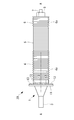
- a therapeutic ultrasonic transducer 10 is a transducer main body (hereinafter simply referred to as “main body”) 1 composed of a bolt-clamped Langevin type (BLT) transducer. And a heat radiating tube 2 for housing the main body 1.
- Reference numeral 14 denotes an electrically insulating outer cylinder that covers the outside of the therapeutic ultrasonic transducer 10.
- the main body 1 includes a horn 3, a first metal body 4, a multilayer body 5 composed of a plurality of piezoelectric elements, and a second metal body 6 in order along the longitudinal axis A from the front end side. . Furthermore, the main body 1 includes a bolt 7 and a nut 8 for fastening the first metal body 4, the laminated body 5 and the second metal body 6 together.
- the piezoelectric element is a plate-like member made of a piezoelectric material such as PZT (titanium zircoate) and is polarized in the thickness direction.
- the laminated body 5 is formed by laminating a plurality of piezoelectric elements in the longitudinal axis A direction so that the polarization directions are alternately reversed.
- the first metal body 4 and the second metal body 6 are columnar members made of an alloy or ceramics (for example, duralumin) whose main component is aluminum.
- a large number of heat radiating grooves 4a, 6a extending in the circumferential direction are formed on the outer peripheral surfaces of the metal bodies 4, 6 at intervals in the longitudinal axis A direction. The surface areas of the metal bodies 4 and 6 are increased by the heat radiating grooves 4a and 6a, and the heat radiation from the metal bodies 4 and 6 is promoted.
- the horn 3 and the bolt 7 are a single member made of a metal having high ultrasonic propagation efficiency and high strength.
- the horn 3 and the bolt 7 are preferably made of a 64 titanium alloy (ASTM standard B348 Grade 5).
- the horn 3 has a substantially conical shape that tapers toward the tip.
- the bolt 7 extends straight along the longitudinal axis A from the base end face of the horn 3 toward the base end side.
- the first metal body 4, the laminated body 5, and the second metal body 6 are formed with bolt holes 9 that penetrate along the longitudinal axis A and into which the bolts 7 are inserted.
- the nut 8 is fastened to the tip end portion of the bolt 7 protruding from the base end surface of the second metal body 6, whereby the laminate 5 is firmly secured from both sides by the first metal body 4 and the second metal body 6. It is tightened to.
- the nut 8 may be omitted, and the second metal body 6 may also serve as the nut 8 by having a female screw that is fastened to the bolt 7.
- the laminate 5 When high frequency power from a high frequency power source (not shown) is applied to the laminate 5, the laminate 5 generates longitudinal vibration in the direction of the longitudinal axis A, and the generated longitudinal vibration is transmitted to the horn 3 via the bolt 7, The tip of the horn 3 vibrates in the direction of the longitudinal axis A. At this time, the longitudinal vibration is amplified while it is transmitted from the proximal end of the horn 3 to the distal end, whereby a vibration having a large amplitude is obtained at the distal end of the horn 3.
- the frequency of the high-frequency power is selected from the range of 20 kHz or more and 100 kHz or less so that the distal end, the intermediate position, and the proximal end of the main body 1 are antinodes of longitudinal vibration.
- arrows N1 and N2 indicate nodes of longitudinal vibration.
- the main body 1 further includes an annular flange portion 11 made of a metal having high thermal conductivity and protruding outward in the radial direction at or near the position of the node N1 on the distal end side. That is, the attachment position of the flange portion 11 to the main body 1 in the longitudinal axis A direction is a position where the vibration speed is zero.
- the vibration speed ratio V1 / V2 is preferably 0.05 or more and 0.3 or less.
- the horn 3 When the vibration speed ratio V1 / V2 is larger than 0.3, the horn 3 is connected to the metal body 4 at a position where the vibration speed is high, thereby causing longitudinal vibration in the original longitudinal axis A direction such as displacement vibration. There is a possibility that vibration other than vibration is generated and heat is easily generated, and the heat radiation performance by the heat radiating pipe 2 described later cannot be sufficiently obtained.
- the boundary surface B between different types of metals is arranged at the node N1, the strength may be insufficient. Therefore, it is preferable to arrange the boundary surface B between the horn 3 and the metal body 4 at a position slightly separated from the node N1 where the vibration speed ratio V1 / V2 is 0.05 or more.
- the heat radiating tube 2 is a cylindrical member made of a metal having high thermal conductivity, and houses the main body 1 in a state in which the tip portion of the horn 3 protrudes from the opening at the tip.
- a large number of radiating fins 2 a extending in the circumferential direction are arranged on the outer peripheral surface of the radiating tube 2 at intervals in the longitudinal axis A direction.
- the heat radiating tube 2 is fixed to the outer peripheral surface of the flange portion 11.
- the therapeutic ultrasonic transducer 10 is mounted on an ultrasonic treatment apparatus that performs treatments such as tissue crushing and dissolution by applying ultrasonic vibration to tissue in a living body.
- high frequency power having a frequency in the range of 20 kHz to 100 kHz
- the laminate 5 generates longitudinal vibration in the longitudinal axis A direction, and the tip of the horn 3 Vibrates ultrasonically. Accordingly, by bringing the tip of the horn 3 that vibrates ultrasonically into contact with the affected part, treatments such as crushing and dissolving the affected part can be performed.
- the heat generated in the main body 1 is released to the outside of the heat radiating pipe 2 by the heat radiating grooves 4a and 6a provided in the metal bodies 4 and 6 and the heat radiating pipe 2 provided outside the main body 1, and further, the outer cylinder 14 is discharged to the outside. Thereby, overheating of the main body 1 is suppressed.
- the amount of heat generation is maximized at the positions of the nodes N1 and N2 where the distortion amount is maximum.
- the heat radiating pipe 2 Since the heat radiating pipe 2 is connected to the position of the node N1 of the main body 1 through the flange portion 11, the heat of the main body 1 is released through the heat radiating pipe 2 with high efficiency. Therefore, even when the high frequency power supplied to the laminate 5 is increased to increase the treatment amplitude by increasing the vibration amplitude at the tip of the horn 3, the therapeutic ultrasonic transducer 10 operates without overheating. There is an advantage that it can continue and can continue to exhibit high treatment performance.
- the conventional BLT vibrator generally uses titanium as the metal body, but the therapeutic ultrasonic vibrator 10 according to the present embodiment is made of aluminum having much higher thermal conductivity than titanium.
- Metal bodies 4 and 6 are used. Therefore, there is an advantage that the heat generated in the laminated body 5 can be more efficiently released through the metal body 4 and the heat radiating pipe 2 and the entire length of the main body 1 can be shortened.
- a plurality of radiating fins 6 b extending in the direction of the longitudinal axis A may be provided at intervals on the base end surface of the second metal body 6.
- the radiation fins 6 b are arranged in the circumferential direction with the longitudinal axis A as the center.
- the heat radiating fins 6b can be further improved without affecting the treatment operation of the therapeutic ultrasonic transducer 10.
- the main body 1 and the heat radiating pipe 2 are connected via the flange portion 11 at the node N1 on the distal end side.
- the main body 1 and the heat radiating tube 2 may be connected at the node N ⁇ b> 2 on the proximal end side.
- the node N2 is located in the stacked body 5. Therefore, the metal plate 12 sandwiched between the two piezoelectric elements is further provided.
- the metal plate 12 has a diameter larger than that of the piezoelectric element, and the peripheral portion of the metal plate 12 protrudes from the outer peripheral surface of the stacked body 5 in a flange shape in the radial direction.
- the heat radiating tube 2 is connected and fixed to the peripheral portion or the outer peripheral surface of the metal plate 12. Even if it does in this way, the heat dissipation effect similar to the structure shown by FIG. 1A and FIG. 1B can be acquired.
- a therapeutic ultrasonic transducer 20 according to a second embodiment of the present invention will be described with reference to FIGS. 5A to 7.
- the therapeutic ultrasonic transducer 20 according to the present embodiment is different from the therapeutic ultrasonic transducer 10 according to the first embodiment in that a Peltier element 13 is provided instead of the heat radiating tube 2. Therefore, in the present embodiment, the Peltier element 13 will be mainly described, and the same reference numerals will be given to the same components as those in the first embodiment, and the description thereof will be omitted.
- the therapeutic ultrasonic transducer 20 includes a metal plate 12 as shown in FIGS. 5A and 5B.
- the metal plate 12 is the same as the metal plate 12 shown in FIG.
- a plurality of Peltier elements 13 are disposed on an annular peripheral portion (flange portion) 12a of the metal plate 12 that protrudes in a flange shape in the radial direction from the outer peripheral surface of the laminated body 5, and the heat absorption surface of the metal plate 12 It fixes with the adhesive along with the circumferential direction so that it may contact.
- Each Peltier element 13 absorbs heat from the laminated body 5 through the metal plate 12 and supplies heat from the heat dissipation surface opposite to the heat absorption surface when current is supplied through an electric wire (not shown). ing.
- the heat generated in the main body 1 by the supply of the high-frequency power to the laminate 5 is absorbed by the Peltier element 13, and from the heat dissipation surface of the Peltier element 13. It is discharged and further discharged to the outside of the outer cylinder 14. Thereby, overheating of the main body 1 is suppressed.
- the Peltier element 13 is connected via the metal plate 12 to the position of the node N2 where the amount of heat generation is maximum in the main body 1, the heat of the main body 1 is released by the Peltier element 13 with high efficiency.
- the therapeutic ultrasonic transducer 20 operates without overheating. There is an advantage that it can continue and can continue to exhibit high treatment performance. Since other effects are the same as those of the first embodiment, description thereof is omitted.
- the Peltier element 13 may be provided also on the base end face of the second metal body 6.
- FIG. 6 shows a second metal body 6 that also serves as a nut, and a Peltier element 13 is fixed to a flat base end face of the second metal body 6.
- the Peltier element 13 is connected to the position of the node N2 on the base end side of the main body 1 via the metal plate 12, but instead of or in addition to this, FIG. As shown in FIG. 4, the Peltier element 13 may be connected to the position of the node N1 on the distal end side of the main body 1. In this case, the Peltier element 13 may be fixed to the surface of the flange portion 11 described above. Moreover, you may use suitably combining the thermal radiation pipe
- the shapes of the heat radiating grooves 4a and 6a and the heat radiating fins 2a can be appropriately changed.
- the heat radiating grooves 4a and 6a may be formed in the longitudinal axis A direction at intervals in the circumferential direction.
- the heat radiating fins 2a may be formed in the direction of the longitudinal axis A with an interval in the circumferential direction.
- Vibrator body Heat radiation pipe (heat radiation means) 2a Radiation fin 3 Horn 4, 6 Metal bodies 4a, 6a Radiation groove 5 Laminated body b Radiation fin 7 Bolt 8 Nut 9 Bolt hole 10, 20 Therapeutic ultrasonic transducer 11 Flange portion 12 Metal plate 12a Peripheral portion (flange portion) 13 Peltier element (heat dissipation means)
Landscapes
- Health & Medical Sciences (AREA)
- Life Sciences & Earth Sciences (AREA)
- Engineering & Computer Science (AREA)
- General Health & Medical Sciences (AREA)
- Public Health (AREA)
- Veterinary Medicine (AREA)
- Nuclear Medicine, Radiotherapy & Molecular Imaging (AREA)
- Biomedical Technology (AREA)
- Animal Behavior & Ethology (AREA)
- Surgery (AREA)
- Radiology & Medical Imaging (AREA)
- Medical Informatics (AREA)
- Molecular Biology (AREA)
- Heart & Thoracic Surgery (AREA)
- Dentistry (AREA)
- Mechanical Engineering (AREA)
- Surgical Instruments (AREA)
- Apparatuses For Generation Of Mechanical Vibrations (AREA)
Abstract
本発明の治療用超音波振動子(10)は、長手軸に沿って順に、第1の金属体(4)と、複数の圧電素子を分極方向が交互に逆方向となるように長手軸方向に積層してなる積層体(5)と、第2の金属体(6)とを有し、金属体(4,6)および積層体(5)をボルト(7)によって一体に締結してなる振動子本体(1)と、該振動子本体(1)の、超音波振動の節となる位置またはその近傍に接続された放熱手段(2)とを備え、20kHz以上100kHz以下の周波数の超音波振動を発生する。
Description
本発明は、治療用超音波振動子に関し、特に、超音波処置具に搭載されるボルト締めランジュバン型の治療用超音波振動子に関するものである。
従来、超音波処置具用の超音波振動子として、ボルト締めランジュバン型(BLT)振動子が使用されている(例えば、特許文献1,2参照。)。BLT振動子は、圧電素子を、アルミ合金やチタン合金のような高剛性の一対の金属体の間に挟み、圧電素子と一対の金属体とをボルトで強固に締結したものである。このような振動子は、強力な超音波振動を発生することができる。
超音波処置具の処置性能は、超音波振動子が発生する超音波振動の強さに依存する。しかし、超音波振動を増強するために超音波振動子に供給する電力を増大すると、超音波振動子の発熱量が増大する。そこで、超音波振動子からの放熱を促進する手段を備えた超音波処置具が知られている(例えば、特許文献3参照。)。特許文献3の超音波処置具は、超音波振動子を内蔵するケースの外側表面に放熱フィンを設けることによって、超音波振動子からケースに伝達された熱の放出を図っている。
骨や軟骨、石灰化組織のような硬い組織の処置する場合、特に強力な超音波振動が必要とされ、超音波振動子への供給電力を増大する必要がある。このような使用においては、超音波振動子の発熱量が特許文献3の放熱フィンによる放熱性能を超えてしまい、特許文献3の放熱フィンでは超音波振動子の過熱を抑制することができないという問題がある。超音波振動子が一度過熱してしまうと、超音波振動子の温度が正常範囲に下がるまで処置を一時停止しなければならず、全体の処置時間が長くなるという不都合がある。
本発明は、上述した事情に鑑みてなされたものであって、過熱を効果的に抑制し、高い処置性能を発揮し続けることができる治療用超音波振動子を提供することを目的とする。
上記目的を達成するため、本発明は以下の手段を提供する。
本発明は、20kHz以上100kHz以下の周波数の超音波振動を発生する治療用超音波振動子であって、先端側から長手軸に沿って順に、第1の金属体と、複数の圧電素子を分極方向が交互に逆方向となるように前記長手軸方向に積層してなる積層体と、第2の金属体とを有し、前記第1の金属体、前記積層体および前記第2の金属体をボルトによって一体に締結してなる振動子本体と、該振動子本体の、前記超音波振動の節となる位置またはその近傍に接続され、前記振動子本体の熱を該振動子本体の外部へ放出する放熱手段とを備える治療用超音波振動子を提供する。
本発明は、20kHz以上100kHz以下の周波数の超音波振動を発生する治療用超音波振動子であって、先端側から長手軸に沿って順に、第1の金属体と、複数の圧電素子を分極方向が交互に逆方向となるように前記長手軸方向に積層してなる積層体と、第2の金属体とを有し、前記第1の金属体、前記積層体および前記第2の金属体をボルトによって一体に締結してなる振動子本体と、該振動子本体の、前記超音波振動の節となる位置またはその近傍に接続され、前記振動子本体の熱を該振動子本体の外部へ放出する放熱手段とを備える治療用超音波振動子を提供する。
本発明によれば、圧電素子に高周波電力が供給されることによって振動子本体が発生した超音波振動を、振動子本体から直接または他の部材を介して組織に与えることによって、組織に対して粉砕や溶解等の処置を行うことができる。
この場合に、振動子本体のうち、超音波振動による歪み量が最大となり、発熱量が最大となる節の位置に接続された放熱手段によって、振動子本体の熱が高効率で放出されるので、振動子本体の過熱が効果的に抑制される。したがって、圧電素子に大きな高周波電力が供給された場合に、振動子本体は、過熱することなく高い処置性能を発揮し続けることができる。
この場合に、振動子本体のうち、超音波振動による歪み量が最大となり、発熱量が最大となる節の位置に接続された放熱手段によって、振動子本体の熱が高効率で放出されるので、振動子本体の過熱が効果的に抑制される。したがって、圧電素子に大きな高周波電力が供給された場合に、振動子本体は、過熱することなく高い処置性能を発揮し続けることができる。
上記発明においては、前記振動子本体が、前記第1の金属体の先端側に、該第1の金属体と一体に接続されたホーンを有し、前記第1の金属体と前記ホーンとの前記長手軸方向の接続位置は、前記超音波振動の腹の位置における振動速度に対する振動速度の比が0.05以上0.3以下となる位置であることが好ましい。
このようにすることで、比較的脆弱なホーンと第1の金属体との境界面を、大きな応力が発生する節の位置からずれた位置に配置しつつ、ホーンの、長手軸方向の途中位置に位置する節からの良好な放熱効果を得ることができる。
このようにすることで、比較的脆弱なホーンと第1の金属体との境界面を、大きな応力が発生する節の位置からずれた位置に配置しつつ、ホーンの、長手軸方向の途中位置に位置する節からの良好な放熱効果を得ることができる。
上記発明においては、前記放熱手段が、前記振動子本体を前記長手軸方向に収容し、その外周面に半径方向外方に突出する複数の放熱フィンを有する筒状の放熱管を備えていてもよい。
このようにすることで、振動子本体の外周面を覆う大面積の放熱管によって、全体の径寸法をほとんど増加することなく、高い放熱性能を得ることができる。
このようにすることで、振動子本体の外周面を覆う大面積の放熱管によって、全体の径寸法をほとんど増加することなく、高い放熱性能を得ることができる。
上記発明においては、前記振動子本体が、前記節となる位置またはその近傍に、半径方向外方に突出するフランジ部を備え、前記放熱手段が、前記フランジ部に固定されたペルチェ素子を備えていてもよい。
このようにすることで、ペルチェ素子によって振動子本体から能動的に吸熱することによって、高い放熱性能を得ることができる。
このようにすることで、ペルチェ素子によって振動子本体から能動的に吸熱することによって、高い放熱性能を得ることができる。
上記発明においては、前記第1の金属体および前記第2の金属体が、その外周面に形成された複数の放熱溝を有していてもよい。
上記発明においては、前記第2の金属体が、その基端面に、前記長手軸方向に延びる複数の放熱フィンを備えていてもよい。
このようにすることで、節の位置のみならず、金属体の外表面からも効率的に放熱されるので、放熱性能をさらに向上することができる。
上記発明においては、前記第2の金属体が、その基端面に、前記長手軸方向に延びる複数の放熱フィンを備えていてもよい。
このようにすることで、節の位置のみならず、金属体の外表面からも効率的に放熱されるので、放熱性能をさらに向上することができる。
本発明によれば、過熱を効果的に抑制し、高い処置性能を発揮し続けることができるという効果を奏する。
(第1の実施形態)
以下に、本発明の第1の実施形態に係る治療用超音波振動子10について図1Aから図4を参照して説明する。
本実施形態に係る治療用超音波振動子10は、図1Aおよび図1Bに示されるように、ボルト締めランジュバン型(BLT)振動子からなる振動子本体(以下、単に「本体」という。)1と、該本体1を収容する放熱管2とを備えている。符号14は、治療用超音波振動子10の外側を被覆する電気絶縁性の外筒である。
以下に、本発明の第1の実施形態に係る治療用超音波振動子10について図1Aから図4を参照して説明する。
本実施形態に係る治療用超音波振動子10は、図1Aおよび図1Bに示されるように、ボルト締めランジュバン型(BLT)振動子からなる振動子本体(以下、単に「本体」という。)1と、該本体1を収容する放熱管2とを備えている。符号14は、治療用超音波振動子10の外側を被覆する電気絶縁性の外筒である。
本体1は、先端側から長手軸Aに沿って順に、ホーン3と、第1の金属体4と、複数枚の圧電素子からなる積層体5と、第2の金属体6とを備えている。さらに、本体1は、第1の金属体4、積層体5および第2の金属体6を一体に締結するための、ボルト7とナット8とを備えている。
圧電素子は、PZT(チタンジルコ酸塩)のような圧電材料からなる板状の部材であって、厚さ方向に分極している。積層体5は、複数枚の圧電素子が、分極方向が交互に逆方向になるように長手軸A方向に積層されてなる。
第1の金属体4および第2の金属体6は、アルミニウムを主成分とする合金またはセラミックス(例えば、ジュラルミン)からなる柱状の部材である。金属体4,6の外周面には、周方向に延びる多数の放熱溝4a,6aが長手軸A方向に間隔を空けて形成されている。放熱溝4a,6aによって各金属体4,6の表面積が増大し、金属体4,6からの放熱が促進されるようになっている。
第1の金属体4および第2の金属体6は、アルミニウムを主成分とする合金またはセラミックス(例えば、ジュラルミン)からなる柱状の部材である。金属体4,6の外周面には、周方向に延びる多数の放熱溝4a,6aが長手軸A方向に間隔を空けて形成されている。放熱溝4a,6aによって各金属体4,6の表面積が増大し、金属体4,6からの放熱が促進されるようになっている。
ホーン3およびボルト7は、高い超音波伝播効率と高い強度とを有する金属からなる単一の部材である。ホーン3およびボルト7は、好ましくは、64チタン合金(ASTM規格のB348 Grade5)からなる。ホーン3は、先端に向かって先細となる略円錐状である。ボルト7は、ホーン3の基端面から基端側へ向かって長手軸Aに沿って真っ直ぐに延びている。
第1の金属体4、積層体5および第2の金属体6には、長手軸Aに沿って貫通し、ボルト7が挿入されるボルト穴9が形成されている。ナット8は、第2の金属体6の基端面から突出するボルト7の先端部分に締結され、これによって、積層体5が第1の金属体4と第2の金属体6とによって両側から強固に締め付けられている。なお、ナット8を省略し、第2の金属体6が、ボルト7と締結する雌ねじを有することによってナット8を兼ねていてもよい。
図示しない高周波電源からの高周波電力が積層体5に印加されると、積層体5が長手軸A方向の縦振動を発生し、発生された縦振動がボルト7を介してホーン3に伝達され、ホーン3の先端が長手軸A方向に振動する。このときに、縦振動が、ホーン3の基端から先端へ伝達する間に増幅されることによって、ホーン3の先端において大きな振幅の振動が得られる。ここで、高周波電力の周波数は、図2Aおよび図2Bに示されるように、本体1の先端、中間位置および基端が縦振動の腹となるように、20kHz以上100kHz以下の範囲内から選択される。図2Aにおいて、矢印N1,N2が縦振動の節を示している。
本体1はさらに、先端側の節N1の位置またはその近傍に、半径方向外方に突出し、高い熱伝導性を有する金属からなる環状のフランジ部11を備えている。すなわち、フランジ部11の、本体1への長手軸A方向の取り付け位置は、振動速度が0となる位置である。
金属体4と、フランジ部11を有するホーン3との境界面Bでの縦振動の振動速度をV1とし、腹の位置での縦振動の振動速度をV2としたときに、振動速度比V1/V2は、0.05以上0.3以下であることが好ましい。振動速度比V1/V2が0.3よりも大きい場合には、ホーン3が、振動速度の速い位置において金属体4に接続されることによって、ズレ振動などの、本来の長手軸A方向の縦振動以外の振動が発生して発熱し易くなり、後述する放熱管2による放熱性能を十分に得られない可能性がある。一方、互いに異なる種類の金属同士の境界面Bを節N1に配置した場合には、強度不足になり得る。そのため、ホーン3と金属体4との境界面Bは、節N1から若干離れた、振動速度比V1/V2が0.05以上となる位置に配することが好ましい。
金属体4と、フランジ部11を有するホーン3との境界面Bでの縦振動の振動速度をV1とし、腹の位置での縦振動の振動速度をV2としたときに、振動速度比V1/V2は、0.05以上0.3以下であることが好ましい。振動速度比V1/V2が0.3よりも大きい場合には、ホーン3が、振動速度の速い位置において金属体4に接続されることによって、ズレ振動などの、本来の長手軸A方向の縦振動以外の振動が発生して発熱し易くなり、後述する放熱管2による放熱性能を十分に得られない可能性がある。一方、互いに異なる種類の金属同士の境界面Bを節N1に配置した場合には、強度不足になり得る。そのため、ホーン3と金属体4との境界面Bは、節N1から若干離れた、振動速度比V1/V2が0.05以上となる位置に配することが好ましい。
放熱管2は、高い熱伝導性を有する金属からなる筒状の部材であり、その先端の開口部からホーン3の先端部分を突出させた状態で本体1を収容している。放熱管2の外周面には、周方向に延びる多数の放熱フィン2aが長手軸A方向に間隔を空けて配列して設けられている。放熱管2は、フランジ部11の外周面に固定されている。
次に、このように構成された治療用超音波振動子10の作用について説明する。
本実施形態に係る治療用超音波振動子10は、生体内の組織に超音波振動を与えることによって組織の粉砕や溶解等の処置を行う超音波処置装置に搭載されるものである。超音波処置装置が備える高周波電源から、20kHz以上100kHz以下の範囲の周波数の高周波電力が積層体5に供給されると、積層体5が長手軸A方向の縦振動を発生し、ホーン3の先端が超音波振動する。したがって、超音波振動するホーン3の先端を患部に接触させることによって、患部の粉砕や溶解等の処置を行うことができる。
本実施形態に係る治療用超音波振動子10は、生体内の組織に超音波振動を与えることによって組織の粉砕や溶解等の処置を行う超音波処置装置に搭載されるものである。超音波処置装置が備える高周波電源から、20kHz以上100kHz以下の範囲の周波数の高周波電力が積層体5に供給されると、積層体5が長手軸A方向の縦振動を発生し、ホーン3の先端が超音波振動する。したがって、超音波振動するホーン3の先端を患部に接触させることによって、患部の粉砕や溶解等の処置を行うことができる。
この場合に、本実施形態によれば、積層体5に供給された高周波電力のうち、大部分は機械的振動に変化されるが、一部は熱に変換される。本体1において生じた熱は、金属体4,6に設けられた放熱溝4a,6aと本体1の外側に設けられた放熱管2とによって、該放熱管2の外部に放出され、さらに外筒14の外部に放出される。これにより、本体1の過熱が抑制される。特に、本体1のうち、歪み量が最大となる節N1,N2の位置において発熱量が最大となる。放熱管2は、フランジ部11を介して本体1の節N1の位置に連結されているので、本体1の熱が高効率で放熱管2を介して放出される。したがって、ホーン3の先端の振動振幅を増大して処置性能を高めるために、積層体5に供給する高周波電力を増大した場合にも、治療用超音波振動子10は、過熱することなく作動し続けることができ、高い処置性能を発揮し続けることができることができるという利点がある。
さらに、従来のBLT振動子は一般に、金属体としてチタン製を使用しているが、本実施形態に係る治療用超音波振動子10は、チタンよりもはるかに高い熱伝導率を有するアルミニウム製の金属体4,6を使用している。したがって、積層体5において発生した熱を、金属体4および放熱管2を介してさらに効率的に放出することができ、本体1全体の全長を短くすることができるという利点がある。
本実施形態においては、図3Aおよび図3Bに示されるように、第2の金属体6の基端面に、長手軸A方向に延びる複数の放熱フィン6bが間隔を空けて設けられていてもよい。図3Aおよび図3Bの例では、放熱フィン6bは、長手軸Aを中心とする周方向に配列して設けられている。
本体1のうち、組織に対して仕事を行うのはホーン3の先端部分のみである。そこで、本体1の基端に放熱フィン6bを設けることによって、治療用超音波振動子10の処置動作に影響を与えることなく、治療用超音波振動子10の放熱性能をさらに向上することができる。
本体1のうち、組織に対して仕事を行うのはホーン3の先端部分のみである。そこで、本体1の基端に放熱フィン6bを設けることによって、治療用超音波振動子10の処置動作に影響を与えることなく、治療用超音波振動子10の放熱性能をさらに向上することができる。
本実施形態においては、縦振動の2つの節N1,N2のうち、先端側の節N1において本体1と放熱管2とをフランジ部11を介して接続することとしたが、これに代えて、またはこれに加えて、図4に示されるように、基端側の節N2において本体1と放熱管2とを接続してもよい。
この場合、節N2は積層体5に位置する。したがって、2枚の圧電素子の間に挟まれた金属板12がさらに設けられる。金属板12は圧電素子よりも大径であり、金属板12の周縁部分は、積層体5の外周面から半径方向にフランジ状に突出している。放熱管2は、金属板12の周縁部分または外周面に連結固定される。
このようにしても、図1Aおよび図1Bに示される構成と同様の放熱効果を得ることができる。
この場合、節N2は積層体5に位置する。したがって、2枚の圧電素子の間に挟まれた金属板12がさらに設けられる。金属板12は圧電素子よりも大径であり、金属板12の周縁部分は、積層体5の外周面から半径方向にフランジ状に突出している。放熱管2は、金属板12の周縁部分または外周面に連結固定される。
このようにしても、図1Aおよび図1Bに示される構成と同様の放熱効果を得ることができる。
(第2の実施形態)
次に、本発明の第2の実施形態に係る治療用超音波振動子20について図5Aから図7を参照して説明する。
本実施形態に係る治療用超音波振動子20は、放熱管2に代えて、ペルチェ素子13を備えている点において、第1の実施形態に係る治療用超音波振動子10と異なっている。したがって、本実施形態においては、ペルチェ素子13について主に説明し、その他の第1の実施形態と共通する構成については、同一の符号を付して説明を省略する。
次に、本発明の第2の実施形態に係る治療用超音波振動子20について図5Aから図7を参照して説明する。
本実施形態に係る治療用超音波振動子20は、放熱管2に代えて、ペルチェ素子13を備えている点において、第1の実施形態に係る治療用超音波振動子10と異なっている。したがって、本実施形態においては、ペルチェ素子13について主に説明し、その他の第1の実施形態と共通する構成については、同一の符号を付して説明を省略する。
治療用超音波振動子20は、図5Aおよび図5Bに示されるように、金属板12を備えている。金属板12は、図4に示される金属板12と同様である。金属板12の、積層体5の外周面から半径方向にフランジ状に突出する環状の周縁部分(フランジ部)12aには、複数個のペルチェ素子13が、その吸熱面が金属板12の表面と接触するように、周方向に並んで接着剤によって固定されている。各ペルチェ素子13は、図示しない電線を介して電流が供給されることによって、金属板12を介して積層体5から熱を吸収し、吸熱面と対向する放熱面から熱を放出するようになっている。
このように構成された治療用超音波振動子20によれば、積層体5への高周波電力の供給によって本体1において生じた熱は、ペルチェ素子13によって吸収され、該ペルチェ素子13の放熱面から放出され、さらに外筒14の外部に放出される。これにより、本体1の過熱が抑制される。特に、本体1のうち、発熱量が最大となる節N2の位置にペルチェ素子13が金属板12を介して接続されているので、本体1の熱が高効率でペルチェ素子13によって放出される。したがって、ホーン3の先端の振動振幅を増大して処置性能を高めるために、積層体5に供給する高周波電力を増大した場合にも、治療用超音波振動子20は、過熱することなく作動し続けることができ、高い処置性能を発揮し続けることができるという利点がある。その他の効果は、第1の実施形態と同様であるので、説明を省略する。
本実施形態においては、図6に示されるように、第2の金属体6の基端面にもペルチェ素子13が設けられていてもよい。図6には、ナットを兼ねた第2の金属体6が示されており、第2の金属体6の平坦な基端面にペルチェ素子13が固定されている。このようにすることで、治療用超音波振動子20の処置動作に影響を与えることなく、治療用超音波振動子20の放熱性能をさらに向上することができる。
本実施形態においては、ペルチェ素子13を、本体1の基端側の節N2の位置に、金属板12を介して接続することとしたが、これに代えて、またはこれに加えて、図7に示されるように、本体1の先端側の節N1の位置に、ペルチェ素子13を接続してもよい。この場合、上述したフランジ部11の表面にペルチェ素子13を固定すればよい。
また、第1の実施形態において説明した放熱管2と、第2の実施形態において説明したペルチェ素子13とを、適宜組み合わせて用いてもよい。
また、第1の実施形態において説明した放熱管2と、第2の実施形態において説明したペルチェ素子13とを、適宜組み合わせて用いてもよい。
第1および第2の実施形態においては、放熱溝4a,6aおよび放熱フィン2aの形状は、適宜変更可能である。例えば、図8に示されるように、放熱溝4a,6aが、周方向に間隔を空けて長手軸A方向に形成されていてもよい。同様に、放熱フィン2aも、周方向に間隔を空けて長手軸A方向に形成されていてもよい。
1 振動子本体
2 放熱管(放熱手段)
2a 放熱フィン
3 ホーン
4,6 金属体
4a,6a 放熱溝
5 積層体
b 放熱フィン
7 ボルト
8 ナット
9 ボルト穴
10,20 治療用超音波振動子
11 フランジ部
12 金属板
12a 周縁部分(フランジ部)
13 ペルチェ素子(放熱手段)
2 放熱管(放熱手段)
2a 放熱フィン
3 ホーン
4,6 金属体
4a,6a 放熱溝
5 積層体
b 放熱フィン
7 ボルト
8 ナット
9 ボルト穴
10,20 治療用超音波振動子
11 フランジ部
12 金属板
12a 周縁部分(フランジ部)
13 ペルチェ素子(放熱手段)
Claims (6)
- 20kHz以上100kHz以下の周波数の超音波振動を発生する治療用超音波振動子であって、
先端側から長手軸に沿って順に、第1の金属体と、複数の圧電素子を分極方向が交互に逆方向となるように前記長手軸方向に積層してなる積層体と、第2の金属体とを有し、前記第1の金属体、前記積層体および前記第2の金属体をボルトによって一体に締結してなる振動子本体と、
該振動子本体の、前記超音波振動の節となる位置またはその近傍に接続され、前記振動子本体の熱を該振動子本体の外部へ放出する放熱手段とを備える治療用超音波振動子。 - 前記振動子本体が、前記第1の金属体の先端側に、該第1の金属体と一体に接続されたホーンを有し、
前記第1の金属体と前記ホーンとの前記長手軸方向の接続位置は、前記超音波振動の腹の位置における振動速度に対する振動速度の比が0.05以上0.3以下となる位置である請求項1に記載の治療用超音波振動子。 - 前記放熱手段が、前記振動子本体を前記長手軸方向に収容し、その外周面に半径方向外方に突出する複数の放熱フィンを有する筒状の放熱管を備える請求項1または請求項2に記載の治療用超音波振動子。
- 前記振動子本体が、前記節となる位置またはその近傍に、半径方向外方に突出するフランジ部を備え、
前記放熱手段が、前記フランジ部に固定されたペルチェ素子を備える請求項1から請求項3のいずれかに記載の治療用超音波振動子。 - 前記第1の金属体および前記第2の金属体が、その外周面に形成された複数の放熱溝を有する請求項1から請求項4のいずれかに記載の治療用超音波振動子。
- 前記第2の金属体が、その基端面に、前記長手軸方向に延びる複数の放熱フィンを備える請求項1から請求項5のいずれかに記載の治療用超音波振動子。
Priority Applications (3)
| Application Number | Priority Date | Filing Date | Title |
|---|---|---|---|
| EP15822038.4A EP3170467A4 (en) | 2014-07-18 | 2015-06-22 | Ultrasonic vibrator for medical treatment |
| CN201580014012.2A CN106102622A (zh) | 2014-07-18 | 2015-06-22 | 治疗用超声波振子 |
| US15/271,661 US20170007855A1 (en) | 2014-07-18 | 2016-09-21 | Thereapeutic ultrasonic transducer |
Applications Claiming Priority (2)
| Application Number | Priority Date | Filing Date | Title |
|---|---|---|---|
| JP2014147803A JP5963811B2 (ja) | 2014-07-18 | 2014-07-18 | 治療用超音波振動子 |
| JP2014-147803 | 2014-07-18 |
Related Child Applications (1)
| Application Number | Title | Priority Date | Filing Date |
|---|---|---|---|
| US15/271,661 Continuation US20170007855A1 (en) | 2014-07-18 | 2016-09-21 | Thereapeutic ultrasonic transducer |
Publications (1)
| Publication Number | Publication Date |
|---|---|
| WO2016009788A1 true WO2016009788A1 (ja) | 2016-01-21 |
Family
ID=55078289
Family Applications (1)
| Application Number | Title | Priority Date | Filing Date |
|---|---|---|---|
| PCT/JP2015/067901 WO2016009788A1 (ja) | 2014-07-18 | 2015-06-22 | 治療用超音波振動子 |
Country Status (5)
| Country | Link |
|---|---|
| US (1) | US20170007855A1 (ja) |
| EP (1) | EP3170467A4 (ja) |
| JP (1) | JP5963811B2 (ja) |
| CN (1) | CN106102622A (ja) |
| WO (1) | WO2016009788A1 (ja) |
Cited By (3)
| Publication number | Priority date | Publication date | Assignee | Title |
|---|---|---|---|---|
| JP2019537455A (ja) * | 2016-11-16 | 2019-12-26 | インテグラ ライフサイエンシーズ エヌアール アイルランド リミテッド | 超音波外科手術ハンドピース |
| US20210059698A1 (en) * | 2017-11-10 | 2021-03-04 | C. R. Bard, Inc. | Heat sinks for catheters, and systems and methods thereof |
| US12076388B2 (en) | 2017-11-30 | 2024-09-03 | Aramis Biotechnologies Inc. | Modified norovirus VP1 proteins and VLPS comprising modified norovirus VP1 proteins |
Families Citing this family (19)
| Publication number | Priority date | Publication date | Assignee | Title |
|---|---|---|---|---|
| US8182501B2 (en) | 2004-02-27 | 2012-05-22 | Ethicon Endo-Surgery, Inc. | Ultrasonic surgical shears and method for sealing a blood vessel using same |
| US20070191713A1 (en) | 2005-10-14 | 2007-08-16 | Eichmann Stephen E | Ultrasonic device for cutting and coagulating |
| US7621930B2 (en) | 2006-01-20 | 2009-11-24 | Ethicon Endo-Surgery, Inc. | Ultrasound medical instrument having a medical ultrasonic blade |
| US8523889B2 (en) | 2007-07-27 | 2013-09-03 | Ethicon Endo-Surgery, Inc. | Ultrasonic end effectors with increased active length |
| US8808319B2 (en) | 2007-07-27 | 2014-08-19 | Ethicon Endo-Surgery, Inc. | Surgical instruments |
| US8430898B2 (en) | 2007-07-31 | 2013-04-30 | Ethicon Endo-Surgery, Inc. | Ultrasonic surgical instruments |
| US9044261B2 (en) | 2007-07-31 | 2015-06-02 | Ethicon Endo-Surgery, Inc. | Temperature controlled ultrasonic surgical instruments |
| US8512365B2 (en) | 2007-07-31 | 2013-08-20 | Ethicon Endo-Surgery, Inc. | Surgical instruments |
| US10010339B2 (en) | 2007-11-30 | 2018-07-03 | Ethicon Llc | Ultrasonic surgical blades |
| US8951272B2 (en) | 2010-02-11 | 2015-02-10 | Ethicon Endo-Surgery, Inc. | Seal arrangements for ultrasonically powered surgical instruments |
| US9820768B2 (en) | 2012-06-29 | 2017-11-21 | Ethicon Llc | Ultrasonic surgical instruments with control mechanisms |
| US10357303B2 (en) | 2015-06-30 | 2019-07-23 | Ethicon Llc | Translatable outer tube for sealing using shielded lap chole dissector |
| WO2017109917A1 (ja) | 2015-12-24 | 2017-06-29 | オリンパス株式会社 | 超音波振動子 |
| US10245064B2 (en) | 2016-07-12 | 2019-04-02 | Ethicon Llc | Ultrasonic surgical instrument with piezoelectric central lumen transducer |
| USD847990S1 (en) | 2016-08-16 | 2019-05-07 | Ethicon Llc | Surgical instrument |
| US10779847B2 (en) | 2016-08-25 | 2020-09-22 | Ethicon Llc | Ultrasonic transducer to waveguide joining |
| WO2018070044A1 (ja) | 2016-10-14 | 2018-04-19 | オリンパス株式会社 | 振動伝達体、超音波トランスデューサ構造体及び医療機器 |
| CN111570244A (zh) * | 2020-05-06 | 2020-08-25 | 盈甲医疗器械制造(上海)有限公司 | 一种超声外科器械的超声换能器及其超声外科器械 |
| WO2022269971A1 (ja) * | 2021-06-23 | 2022-12-29 | オリンパス株式会社 | 超音波処置具 |
Citations (7)
| Publication number | Priority date | Publication date | Assignee | Title |
|---|---|---|---|---|
| JPS62227343A (ja) * | 1986-03-28 | 1987-10-06 | オリンパス光学工業株式会社 | 超音波処置装置 |
| JPH0194841A (ja) * | 1987-10-08 | 1989-04-13 | Olympus Optical Co Ltd | 超音波処置具 |
| JPH0199547A (ja) * | 1987-10-13 | 1989-04-18 | Olympus Optical Co Ltd | 超音波処置装置 |
| JPH03151954A (ja) * | 1989-11-07 | 1991-06-28 | Olympus Optical Co Ltd | 超音波治療装置 |
| JPH03155855A (ja) * | 1989-11-14 | 1991-07-03 | Olympus Optical Co Ltd | 超音波治療装置 |
| JP2001321388A (ja) * | 2000-05-17 | 2001-11-20 | Aloka Co Ltd | 超音波手術器 |
| JP2012531260A (ja) * | 2009-06-24 | 2012-12-10 | エシコン・エンド−サージェリィ・インコーポレイテッド | 超音波外科用器具 |
Family Cites Families (13)
| Publication number | Priority date | Publication date | Assignee | Title |
|---|---|---|---|---|
| US3689783A (en) * | 1971-03-11 | 1972-09-05 | David A Williams | Ultrasonic transducer with half-wave separator between piezoelectric crystal means |
| US5076276A (en) * | 1989-11-01 | 1991-12-31 | Olympus Optical Co., Ltd. | Ultrasound type treatment apparatus |
| US5221282A (en) * | 1991-05-29 | 1993-06-22 | Sonokinetics Group | Tapered tip ultrasonic aspirator |
| US5843109A (en) * | 1996-05-29 | 1998-12-01 | Allergan | Ultrasonic handpiece with multiple piezoelectric elements and heat dissipator |
| US6013048A (en) * | 1997-11-07 | 2000-01-11 | Mentor Corporation | Ultrasonic assisted liposuction system |
| US6278218B1 (en) * | 1999-04-15 | 2001-08-21 | Ethicon Endo-Surgery, Inc. | Apparatus and method for tuning ultrasonic transducers |
| EP1591073A4 (en) * | 2003-01-31 | 2010-11-17 | Hitachi Medical Corp | ULTRASONIC PROBE AND ULTRASONIC DEVICE |
| US7828754B2 (en) * | 2004-06-21 | 2010-11-09 | Hiroshi Furuhata | Ultrasonic cerebral infarction therapeutic apparatus |
| NL1026492C2 (nl) * | 2004-06-24 | 2005-12-28 | Pan Consult B V | Inrichting voor het met behulp van ultrageluid bestralen van een doelgebied in een menselijk of dierlijk lichaam. |
| DE602005011660D1 (de) * | 2004-10-27 | 2009-01-22 | Toshiba Kk | Ultraschallsonde und Ultraschallgerät |
| US8808319B2 (en) * | 2007-07-27 | 2014-08-19 | Ethicon Endo-Surgery, Inc. | Surgical instruments |
| US20110196438A1 (en) * | 2010-02-10 | 2011-08-11 | Lukas Mnozil | Therapy device and method for treating underlying tissue using electrical and acoustic energies |
| CN102470008B (zh) * | 2010-03-31 | 2015-04-08 | 奥林巴斯医疗株式会社 | 医疗装置 |
-
2014
- 2014-07-18 JP JP2014147803A patent/JP5963811B2/ja active Active
-
2015
- 2015-06-22 CN CN201580014012.2A patent/CN106102622A/zh active Pending
- 2015-06-22 WO PCT/JP2015/067901 patent/WO2016009788A1/ja active Application Filing
- 2015-06-22 EP EP15822038.4A patent/EP3170467A4/en not_active Withdrawn
-
2016
- 2016-09-21 US US15/271,661 patent/US20170007855A1/en not_active Abandoned
Patent Citations (7)
| Publication number | Priority date | Publication date | Assignee | Title |
|---|---|---|---|---|
| JPS62227343A (ja) * | 1986-03-28 | 1987-10-06 | オリンパス光学工業株式会社 | 超音波処置装置 |
| JPH0194841A (ja) * | 1987-10-08 | 1989-04-13 | Olympus Optical Co Ltd | 超音波処置具 |
| JPH0199547A (ja) * | 1987-10-13 | 1989-04-18 | Olympus Optical Co Ltd | 超音波処置装置 |
| JPH03151954A (ja) * | 1989-11-07 | 1991-06-28 | Olympus Optical Co Ltd | 超音波治療装置 |
| JPH03155855A (ja) * | 1989-11-14 | 1991-07-03 | Olympus Optical Co Ltd | 超音波治療装置 |
| JP2001321388A (ja) * | 2000-05-17 | 2001-11-20 | Aloka Co Ltd | 超音波手術器 |
| JP2012531260A (ja) * | 2009-06-24 | 2012-12-10 | エシコン・エンド−サージェリィ・インコーポレイテッド | 超音波外科用器具 |
Non-Patent Citations (1)
| Title |
|---|
| See also references of EP3170467A4 * |
Cited By (8)
| Publication number | Priority date | Publication date | Assignee | Title |
|---|---|---|---|---|
| JP2019537455A (ja) * | 2016-11-16 | 2019-12-26 | インテグラ ライフサイエンシーズ エヌアール アイルランド リミテッド | 超音波外科手術ハンドピース |
| JP7030789B2 (ja) | 2016-11-16 | 2022-03-07 | インテグラ ライフサイエンシーズ エンタープライジーズ, エルエルエルピー | 超音波外科手術ハンドピース |
| JP2022044736A (ja) * | 2016-11-16 | 2022-03-17 | インテグラ ライフサイエンシーズ エンタープライジーズ, エルエルエルピー | 超音波外科手術ハンドピース |
| US11284915B2 (en) | 2016-11-16 | 2022-03-29 | Integra Lifesciences Enterprises, Lllp | Ultrasonic surgical handpiece having a thermal diffuser |
| US20210059698A1 (en) * | 2017-11-10 | 2021-03-04 | C. R. Bard, Inc. | Heat sinks for catheters, and systems and methods thereof |
| US11707288B2 (en) * | 2017-11-10 | 2023-07-25 | C.R. Bard, Inc. | Heat sinks for catheters, and systems and methods thereof |
| US20230270458A1 (en) * | 2017-11-10 | 2023-08-31 | C.R. Bard, Inc. | Heat Sinks For Catheters, And Systems And Methods Thereof |
| US12076388B2 (en) | 2017-11-30 | 2024-09-03 | Aramis Biotechnologies Inc. | Modified norovirus VP1 proteins and VLPS comprising modified norovirus VP1 proteins |
Also Published As
| Publication number | Publication date |
|---|---|
| CN106102622A (zh) | 2016-11-09 |
| EP3170467A1 (en) | 2017-05-24 |
| JP2016022136A (ja) | 2016-02-08 |
| JP5963811B2 (ja) | 2016-08-03 |
| EP3170467A4 (en) | 2018-03-21 |
| US20170007855A1 (en) | 2017-01-12 |
Similar Documents
| Publication | Publication Date | Title |
|---|---|---|
| WO2016009788A1 (ja) | 治療用超音波振動子 | |
| JP2016022136A5 (ja) | ||
| JP6326275B2 (ja) | 超音波振動子及び超音波医療装置 | |
| JP4838781B2 (ja) | 超音波振動子及びその製造方法 | |
| US8232705B2 (en) | Thermal transfer and acoustic matching layers for ultrasound transducer | |
| JP2002542005A (ja) | 圧縮圧力の伝達を改良した超音波トランスデューサ | |
| JP6454715B2 (ja) | 超音波接合装置 | |
| JP6091712B1 (ja) | 超音波振動子の製造方法および超音波振動子 | |
| US11383271B2 (en) | Ultrasound transducer | |
| US20100087758A1 (en) | Laminated ultrasonic waveguides fabricated from sheet stock | |
| CN103341241B (zh) | 一种高强度聚焦超声换能器阵列 | |
| CN101142619A (zh) | 用于在液体中产生超声的超声棒式振荡器 | |
| JP2010089007A (ja) | 超音波加工装置 | |
| CN101758017A (zh) | 全方位超声波辐射器 | |
| RU2332266C1 (ru) | Ультразвуковая колебательная система | |
| JP4118728B2 (ja) | 超音波トランスデューサ | |
| JP4529313B2 (ja) | 超音波発生装置 | |
| CN104350277B (zh) | 用于产生气流的装置和布置 | |
| JP5149345B2 (ja) | 超音波振動子 | |
| JP2014144147A (ja) | 超音波振動デバイスおよび超音波医療装置 | |
| JP4827170B2 (ja) | ボルト締めランジュバン型振動子 | |
| JP4419874B2 (ja) | 超音波美容装置 | |
| JP3772601B2 (ja) | 超音波発生装置 | |
| JP7261432B1 (ja) | 超音波放射ユニット | |
| JP2014213324A (ja) | 超音波溶接装置 |
Legal Events
| Date | Code | Title | Description |
|---|---|---|---|
| 121 | Ep: the epo has been informed by wipo that ep was designated in this application |
Ref document number: 15822038 Country of ref document: EP Kind code of ref document: A1 |
|
| NENP | Non-entry into the national phase |
Ref country code: DE |
|
| REEP | Request for entry into the european phase |
Ref document number: 2015822038 Country of ref document: EP |
|
| WWE | Wipo information: entry into national phase |
Ref document number: 2015822038 Country of ref document: EP |