WO2016009788A1 - Vibreur ultrasonore pour traitement médical - Google Patents
Vibreur ultrasonore pour traitement médical Download PDFInfo
- Publication number
- WO2016009788A1 WO2016009788A1 PCT/JP2015/067901 JP2015067901W WO2016009788A1 WO 2016009788 A1 WO2016009788 A1 WO 2016009788A1 JP 2015067901 W JP2015067901 W JP 2015067901W WO 2016009788 A1 WO2016009788 A1 WO 2016009788A1
- Authority
- WO
- WIPO (PCT)
- Prior art keywords
- ultrasonic transducer
- main body
- metal body
- heat radiating
- longitudinal axis
- Prior art date
Links
Images


Classifications
-
- A—HUMAN NECESSITIES
- A61—MEDICAL OR VETERINARY SCIENCE; HYGIENE
- A61N—ELECTROTHERAPY; MAGNETOTHERAPY; RADIATION THERAPY; ULTRASOUND THERAPY
- A61N7/00—Ultrasound therapy
-
- A—HUMAN NECESSITIES
- A61—MEDICAL OR VETERINARY SCIENCE; HYGIENE
- A61B—DIAGNOSIS; SURGERY; IDENTIFICATION
- A61B17/00—Surgical instruments, devices or methods, e.g. tourniquets
- A61B17/32—Surgical cutting instruments
- A61B17/320068—Surgical cutting instruments using mechanical vibrations, e.g. ultrasonic
- A61B2017/320089—Surgical cutting instruments using mechanical vibrations, e.g. ultrasonic node location
Definitions
- the present invention relates to a therapeutic ultrasonic transducer, and more particularly to a bolted Langevin type therapeutic ultrasonic transducer mounted on an ultrasonic treatment instrument.
- BLT Langevin type
- the BLT vibrator is obtained by sandwiching a piezoelectric element between a pair of highly rigid metal bodies such as an aluminum alloy or a titanium alloy, and firmly fastening the piezoelectric element and the pair of metal bodies with bolts. Such a vibrator can generate strong ultrasonic vibrations.
- the treatment performance of the ultrasonic treatment instrument depends on the intensity of ultrasonic vibration generated by the ultrasonic transducer.
- an ultrasonic treatment instrument having means for promoting heat dissipation from the ultrasonic transducer is known (for example, see Patent Document 3).
- the ultrasonic treatment instrument of Patent Document 3 aims to release heat transferred from the ultrasonic transducer to the case by providing a heat radiating fin on the outer surface of the case containing the ultrasonic transducer.
- the present invention has been made in view of the above-described circumstances, and an object thereof is to provide a therapeutic ultrasonic transducer that can effectively suppress overheating and continue to exhibit high treatment performance.
- the present invention is a therapeutic ultrasonic transducer that generates ultrasonic vibrations having a frequency of 20 kHz to 100 kHz, and polarizes a first metal body and a plurality of piezoelectric elements in order along the longitudinal axis from the distal end side.
- a laminated body formed by laminating in the longitudinal axis direction so that directions are alternately reversed; and a second metal body, the first metal body, the laminated body, and the second metal body.
- a therapeutic ultrasonic transducer comprising a heat radiating means for discharging is provided.
- the ultrasonic vibration generated by the vibrator main body by supplying high-frequency power to the piezoelectric element is applied to the tissue directly from the vibrator main body or via another member to the tissue. Treatments such as crushing and dissolution can be performed.
- the heat of the vibrator body is released with high efficiency by the heat radiating means connected to the position of the node where the amount of heat generation is maximized.
- the overheating of the vibrator body is effectively suppressed. Therefore, when a large high-frequency power is supplied to the piezoelectric element, the vibrator body can continue to exhibit high treatment performance without overheating.
- the vibrator main body has a horn integrally connected to the first metal body on the tip side of the first metal body, and the first metal body and the horn
- the connection position in the longitudinal axis direction is preferably a position where the ratio of the vibration speed to the vibration speed at the antinode position of the ultrasonic vibration is 0.05 or more and 0.3 or less.
- the heat radiating means may include a cylindrical heat radiating tube that houses the vibrator main body in the longitudinal axis direction and has a plurality of heat radiating fins protruding radially outward on an outer peripheral surface thereof. Good. By doing in this way, a high heat dissipation performance can be obtained with a large-area heat radiating tube that covers the outer peripheral surface of the vibrator body, with almost no increase in the overall diameter.
- the vibrator main body includes a flange portion protruding radially outward at or near the position to be the node, and the heat radiating means includes a Peltier element fixed to the flange portion. May be. By doing so, high heat dissipation performance can be obtained by actively absorbing heat from the vibrator body by the Peltier element.
- the said 1st metal body and the said 2nd metal body may have several heat dissipation groove formed in the outer peripheral surface.
- the said 2nd metal body may be provided with the several radiation fin extended in the said longitudinal axis direction at the base end surface.
- FIG. 1B is a rear view of the ultrasonic transducer of FIG. 1A viewed from the proximal end side in the longitudinal axis direction. It is a figure which shows the position of the node in the longitudinal vibration of the ultrasonic transducer
- FIG. 1B is a rear view of the ultrasonic transducer of FIG. 1A viewed from the proximal end side in the longitudinal axis direction. It is a figure which shows the position of the node in the longitudinal vibration of the ultrasonic transducer
- FIG. 3B is a rear view of the ultrasonic transducer of FIG. 3A viewed from the base end side in the longitudinal axis direction. It is a side view which shows another modification of the ultrasonic transducer
- FIG. 5B is a rear view of the ultrasonic transducer of FIG. 5A viewed from the proximal end side in the longitudinal axis direction. It is a side view which shows the modification of the ultrasonic transducer
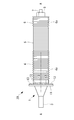
- a therapeutic ultrasonic transducer 10 is a transducer main body (hereinafter simply referred to as “main body”) 1 composed of a bolt-clamped Langevin type (BLT) transducer. And a heat radiating tube 2 for housing the main body 1.
- Reference numeral 14 denotes an electrically insulating outer cylinder that covers the outside of the therapeutic ultrasonic transducer 10.
- the main body 1 includes a horn 3, a first metal body 4, a multilayer body 5 composed of a plurality of piezoelectric elements, and a second metal body 6 in order along the longitudinal axis A from the front end side. . Furthermore, the main body 1 includes a bolt 7 and a nut 8 for fastening the first metal body 4, the laminated body 5 and the second metal body 6 together.
- the piezoelectric element is a plate-like member made of a piezoelectric material such as PZT (titanium zircoate) and is polarized in the thickness direction.
- the laminated body 5 is formed by laminating a plurality of piezoelectric elements in the longitudinal axis A direction so that the polarization directions are alternately reversed.
- the first metal body 4 and the second metal body 6 are columnar members made of an alloy or ceramics (for example, duralumin) whose main component is aluminum.
- a large number of heat radiating grooves 4a, 6a extending in the circumferential direction are formed on the outer peripheral surfaces of the metal bodies 4, 6 at intervals in the longitudinal axis A direction. The surface areas of the metal bodies 4 and 6 are increased by the heat radiating grooves 4a and 6a, and the heat radiation from the metal bodies 4 and 6 is promoted.
- the horn 3 and the bolt 7 are a single member made of a metal having high ultrasonic propagation efficiency and high strength.
- the horn 3 and the bolt 7 are preferably made of a 64 titanium alloy (ASTM standard B348 Grade 5).
- the horn 3 has a substantially conical shape that tapers toward the tip.
- the bolt 7 extends straight along the longitudinal axis A from the base end face of the horn 3 toward the base end side.
- the first metal body 4, the laminated body 5, and the second metal body 6 are formed with bolt holes 9 that penetrate along the longitudinal axis A and into which the bolts 7 are inserted.
- the nut 8 is fastened to the tip end portion of the bolt 7 protruding from the base end surface of the second metal body 6, whereby the laminate 5 is firmly secured from both sides by the first metal body 4 and the second metal body 6. It is tightened to.
- the nut 8 may be omitted, and the second metal body 6 may also serve as the nut 8 by having a female screw that is fastened to the bolt 7.
- the laminate 5 When high frequency power from a high frequency power source (not shown) is applied to the laminate 5, the laminate 5 generates longitudinal vibration in the direction of the longitudinal axis A, and the generated longitudinal vibration is transmitted to the horn 3 via the bolt 7, The tip of the horn 3 vibrates in the direction of the longitudinal axis A. At this time, the longitudinal vibration is amplified while it is transmitted from the proximal end of the horn 3 to the distal end, whereby a vibration having a large amplitude is obtained at the distal end of the horn 3.
- the frequency of the high-frequency power is selected from the range of 20 kHz or more and 100 kHz or less so that the distal end, the intermediate position, and the proximal end of the main body 1 are antinodes of longitudinal vibration.
- arrows N1 and N2 indicate nodes of longitudinal vibration.
- the main body 1 further includes an annular flange portion 11 made of a metal having high thermal conductivity and protruding outward in the radial direction at or near the position of the node N1 on the distal end side. That is, the attachment position of the flange portion 11 to the main body 1 in the longitudinal axis A direction is a position where the vibration speed is zero.
- the vibration speed ratio V1 / V2 is preferably 0.05 or more and 0.3 or less.
- the horn 3 When the vibration speed ratio V1 / V2 is larger than 0.3, the horn 3 is connected to the metal body 4 at a position where the vibration speed is high, thereby causing longitudinal vibration in the original longitudinal axis A direction such as displacement vibration. There is a possibility that vibration other than vibration is generated and heat is easily generated, and the heat radiation performance by the heat radiating pipe 2 described later cannot be sufficiently obtained.
- the boundary surface B between different types of metals is arranged at the node N1, the strength may be insufficient. Therefore, it is preferable to arrange the boundary surface B between the horn 3 and the metal body 4 at a position slightly separated from the node N1 where the vibration speed ratio V1 / V2 is 0.05 or more.
- the heat radiating tube 2 is a cylindrical member made of a metal having high thermal conductivity, and houses the main body 1 in a state in which the tip portion of the horn 3 protrudes from the opening at the tip.
- a large number of radiating fins 2 a extending in the circumferential direction are arranged on the outer peripheral surface of the radiating tube 2 at intervals in the longitudinal axis A direction.
- the heat radiating tube 2 is fixed to the outer peripheral surface of the flange portion 11.
- the therapeutic ultrasonic transducer 10 is mounted on an ultrasonic treatment apparatus that performs treatments such as tissue crushing and dissolution by applying ultrasonic vibration to tissue in a living body.
- high frequency power having a frequency in the range of 20 kHz to 100 kHz
- the laminate 5 generates longitudinal vibration in the longitudinal axis A direction, and the tip of the horn 3 Vibrates ultrasonically. Accordingly, by bringing the tip of the horn 3 that vibrates ultrasonically into contact with the affected part, treatments such as crushing and dissolving the affected part can be performed.
- the heat generated in the main body 1 is released to the outside of the heat radiating pipe 2 by the heat radiating grooves 4a and 6a provided in the metal bodies 4 and 6 and the heat radiating pipe 2 provided outside the main body 1, and further, the outer cylinder 14 is discharged to the outside. Thereby, overheating of the main body 1 is suppressed.
- the amount of heat generation is maximized at the positions of the nodes N1 and N2 where the distortion amount is maximum.
- the heat radiating pipe 2 Since the heat radiating pipe 2 is connected to the position of the node N1 of the main body 1 through the flange portion 11, the heat of the main body 1 is released through the heat radiating pipe 2 with high efficiency. Therefore, even when the high frequency power supplied to the laminate 5 is increased to increase the treatment amplitude by increasing the vibration amplitude at the tip of the horn 3, the therapeutic ultrasonic transducer 10 operates without overheating. There is an advantage that it can continue and can continue to exhibit high treatment performance.
- the conventional BLT vibrator generally uses titanium as the metal body, but the therapeutic ultrasonic vibrator 10 according to the present embodiment is made of aluminum having much higher thermal conductivity than titanium.
- Metal bodies 4 and 6 are used. Therefore, there is an advantage that the heat generated in the laminated body 5 can be more efficiently released through the metal body 4 and the heat radiating pipe 2 and the entire length of the main body 1 can be shortened.
- a plurality of radiating fins 6 b extending in the direction of the longitudinal axis A may be provided at intervals on the base end surface of the second metal body 6.
- the radiation fins 6 b are arranged in the circumferential direction with the longitudinal axis A as the center.
- the heat radiating fins 6b can be further improved without affecting the treatment operation of the therapeutic ultrasonic transducer 10.
- the main body 1 and the heat radiating pipe 2 are connected via the flange portion 11 at the node N1 on the distal end side.
- the main body 1 and the heat radiating tube 2 may be connected at the node N ⁇ b> 2 on the proximal end side.
- the node N2 is located in the stacked body 5. Therefore, the metal plate 12 sandwiched between the two piezoelectric elements is further provided.
- the metal plate 12 has a diameter larger than that of the piezoelectric element, and the peripheral portion of the metal plate 12 protrudes from the outer peripheral surface of the stacked body 5 in a flange shape in the radial direction.
- the heat radiating tube 2 is connected and fixed to the peripheral portion or the outer peripheral surface of the metal plate 12. Even if it does in this way, the heat dissipation effect similar to the structure shown by FIG. 1A and FIG. 1B can be acquired.
- a therapeutic ultrasonic transducer 20 according to a second embodiment of the present invention will be described with reference to FIGS. 5A to 7.
- the therapeutic ultrasonic transducer 20 according to the present embodiment is different from the therapeutic ultrasonic transducer 10 according to the first embodiment in that a Peltier element 13 is provided instead of the heat radiating tube 2. Therefore, in the present embodiment, the Peltier element 13 will be mainly described, and the same reference numerals will be given to the same components as those in the first embodiment, and the description thereof will be omitted.
- the therapeutic ultrasonic transducer 20 includes a metal plate 12 as shown in FIGS. 5A and 5B.
- the metal plate 12 is the same as the metal plate 12 shown in FIG.
- a plurality of Peltier elements 13 are disposed on an annular peripheral portion (flange portion) 12a of the metal plate 12 that protrudes in a flange shape in the radial direction from the outer peripheral surface of the laminated body 5, and the heat absorption surface of the metal plate 12 It fixes with the adhesive along with the circumferential direction so that it may contact.
- Each Peltier element 13 absorbs heat from the laminated body 5 through the metal plate 12 and supplies heat from the heat dissipation surface opposite to the heat absorption surface when current is supplied through an electric wire (not shown). ing.
- the heat generated in the main body 1 by the supply of the high-frequency power to the laminate 5 is absorbed by the Peltier element 13, and from the heat dissipation surface of the Peltier element 13. It is discharged and further discharged to the outside of the outer cylinder 14. Thereby, overheating of the main body 1 is suppressed.
- the Peltier element 13 is connected via the metal plate 12 to the position of the node N2 where the amount of heat generation is maximum in the main body 1, the heat of the main body 1 is released by the Peltier element 13 with high efficiency.
- the therapeutic ultrasonic transducer 20 operates without overheating. There is an advantage that it can continue and can continue to exhibit high treatment performance. Since other effects are the same as those of the first embodiment, description thereof is omitted.
- the Peltier element 13 may be provided also on the base end face of the second metal body 6.
- FIG. 6 shows a second metal body 6 that also serves as a nut, and a Peltier element 13 is fixed to a flat base end face of the second metal body 6.
- the Peltier element 13 is connected to the position of the node N2 on the base end side of the main body 1 via the metal plate 12, but instead of or in addition to this, FIG. As shown in FIG. 4, the Peltier element 13 may be connected to the position of the node N1 on the distal end side of the main body 1. In this case, the Peltier element 13 may be fixed to the surface of the flange portion 11 described above. Moreover, you may use suitably combining the thermal radiation pipe
- the shapes of the heat radiating grooves 4a and 6a and the heat radiating fins 2a can be appropriately changed.
- the heat radiating grooves 4a and 6a may be formed in the longitudinal axis A direction at intervals in the circumferential direction.
- the heat radiating fins 2a may be formed in the direction of the longitudinal axis A with an interval in the circumferential direction.
- Vibrator body Heat radiation pipe (heat radiation means) 2a Radiation fin 3 Horn 4, 6 Metal bodies 4a, 6a Radiation groove 5 Laminated body b Radiation fin 7 Bolt 8 Nut 9 Bolt hole 10, 20 Therapeutic ultrasonic transducer 11 Flange portion 12 Metal plate 12a Peripheral portion (flange portion) 13 Peltier element (heat dissipation means)
Landscapes
- Health & Medical Sciences (AREA)
- Life Sciences & Earth Sciences (AREA)
- Engineering & Computer Science (AREA)
- General Health & Medical Sciences (AREA)
- Public Health (AREA)
- Veterinary Medicine (AREA)
- Nuclear Medicine, Radiotherapy & Molecular Imaging (AREA)
- Biomedical Technology (AREA)
- Animal Behavior & Ethology (AREA)
- Surgery (AREA)
- Radiology & Medical Imaging (AREA)
- Medical Informatics (AREA)
- Molecular Biology (AREA)
- Heart & Thoracic Surgery (AREA)
- Dentistry (AREA)
- Mechanical Engineering (AREA)
- Surgical Instruments (AREA)
- Apparatuses For Generation Of Mechanical Vibrations (AREA)
Abstract
L'invention concerne un vibreur ultrasonore pour un traitement médical (10) présentant, dans l'ordre suivant le long de l'axe longitudinal, les éléments suivants : un premier corps métallique (4) ; un corps stratifié (5) dans lequel de multiples éléments piézoélectriques sont stratifiés dans la direction axiale longitudinale de telle sorte que les directions de polarisation correspondantes sont réglées pour être des directions opposées en alternance ; et un deuxième corps métallique (6). Le vibreur ultrasonore est en outre pourvu : d'un corps d'oscillateur (1) formé par la fixation en une seule pièce des corps métalliques (4, 6) et du corps stratifié (5) à l'aide d'un boulon ; et d'un moyen de dissipation thermique (2) relié à un emplacement, sur le corps d'oscillateur (1), qui sert de noeud pour les vibrations ultrasonores, ou dans le voisinage d'un tel emplacement. Les vibrations ultrasonores sont générées à une fréquence de 20 à 100 kHz inclus.
Priority Applications (3)
| Application Number | Priority Date | Filing Date | Title |
|---|---|---|---|
| CN201580014012.2A CN106102622A (zh) | 2014-07-18 | 2015-06-22 | 治疗用超声波振子 |
| EP15822038.4A EP3170467A4 (fr) | 2014-07-18 | 2015-06-22 | Vibreur ultrasonore pour traitement médical |
| US15/271,661 US20170007855A1 (en) | 2014-07-18 | 2016-09-21 | Thereapeutic ultrasonic transducer |
Applications Claiming Priority (2)
| Application Number | Priority Date | Filing Date | Title |
|---|---|---|---|
| JP2014-147803 | 2014-07-18 | ||
| JP2014147803A JP5963811B2 (ja) | 2014-07-18 | 2014-07-18 | 治療用超音波振動子 |
Related Child Applications (1)
| Application Number | Title | Priority Date | Filing Date |
|---|---|---|---|
| US15/271,661 Continuation US20170007855A1 (en) | 2014-07-18 | 2016-09-21 | Thereapeutic ultrasonic transducer |
Publications (1)
| Publication Number | Publication Date |
|---|---|
| WO2016009788A1 true WO2016009788A1 (fr) | 2016-01-21 |
Family
ID=55078289
Family Applications (1)
| Application Number | Title | Priority Date | Filing Date |
|---|---|---|---|
| PCT/JP2015/067901 WO2016009788A1 (fr) | 2014-07-18 | 2015-06-22 | Vibreur ultrasonore pour traitement médical |
Country Status (5)
| Country | Link |
|---|---|
| US (1) | US20170007855A1 (fr) |
| EP (1) | EP3170467A4 (fr) |
| JP (1) | JP5963811B2 (fr) |
| CN (1) | CN106102622A (fr) |
| WO (1) | WO2016009788A1 (fr) |
Cited By (2)
| Publication number | Priority date | Publication date | Assignee | Title |
|---|---|---|---|---|
| JP2019537455A (ja) * | 2016-11-16 | 2019-12-26 | インテグラ ライフサイエンシーズ エヌアール アイルランド リミテッド | 超音波外科手術ハンドピース |
| US20210059698A1 (en) * | 2017-11-10 | 2021-03-04 | C. R. Bard, Inc. | Heat sinks for catheters, and systems and methods thereof |
Families Citing this family (16)
| Publication number | Priority date | Publication date | Assignee | Title |
|---|---|---|---|---|
| US8182501B2 (en) | 2004-02-27 | 2012-05-22 | Ethicon Endo-Surgery, Inc. | Ultrasonic surgical shears and method for sealing a blood vessel using same |
| US20070191713A1 (en) | 2005-10-14 | 2007-08-16 | Eichmann Stephen E | Ultrasonic device for cutting and coagulating |
| US8808319B2 (en) | 2007-07-27 | 2014-08-19 | Ethicon Endo-Surgery, Inc. | Surgical instruments |
| US8523889B2 (en) | 2007-07-27 | 2013-09-03 | Ethicon Endo-Surgery, Inc. | Ultrasonic end effectors with increased active length |
| US8430898B2 (en) | 2007-07-31 | 2013-04-30 | Ethicon Endo-Surgery, Inc. | Ultrasonic surgical instruments |
| US8512365B2 (en) | 2007-07-31 | 2013-08-20 | Ethicon Endo-Surgery, Inc. | Surgical instruments |
| US10010339B2 (en) | 2007-11-30 | 2018-07-03 | Ethicon Llc | Ultrasonic surgical blades |
| US8951272B2 (en) | 2010-02-11 | 2015-02-10 | Ethicon Endo-Surgery, Inc. | Seal arrangements for ultrasonically powered surgical instruments |
| US9820768B2 (en) | 2012-06-29 | 2017-11-21 | Ethicon Llc | Ultrasonic surgical instruments with control mechanisms |
| US10357303B2 (en) | 2015-06-30 | 2019-07-23 | Ethicon Llc | Translatable outer tube for sealing using shielded lap chole dissector |
| JP6261833B2 (ja) | 2015-12-24 | 2018-01-17 | オリンパス株式会社 | 超音波振動子、超音波処置具、および超音波治療装置 |
| US10245064B2 (en) | 2016-07-12 | 2019-04-02 | Ethicon Llc | Ultrasonic surgical instrument with piezoelectric central lumen transducer |
| US10736649B2 (en) | 2016-08-25 | 2020-08-11 | Ethicon Llc | Electrical and thermal connections for ultrasonic transducer |
| WO2018070044A1 (fr) | 2016-10-14 | 2018-04-19 | オリンパス株式会社 | Corps de transmission de vibrations, structure de transducteur ultrasonique, et instrument médical |
| CN111570244A (zh) * | 2020-05-06 | 2020-08-25 | 盈甲医疗器械制造(上海)有限公司 | 一种超声外科器械的超声换能器及其超声外科器械 |
| JPWO2022269971A1 (fr) * | 2021-06-23 | 2022-12-29 |
Citations (7)
| Publication number | Priority date | Publication date | Assignee | Title |
|---|---|---|---|---|
| JPS62227343A (ja) * | 1986-03-28 | 1987-10-06 | オリンパス光学工業株式会社 | 超音波処置装置 |
| JPH0194841A (ja) * | 1987-10-08 | 1989-04-13 | Olympus Optical Co Ltd | 超音波処置具 |
| JPH0199547A (ja) * | 1987-10-13 | 1989-04-18 | Olympus Optical Co Ltd | 超音波処置装置 |
| JPH03151954A (ja) * | 1989-11-07 | 1991-06-28 | Olympus Optical Co Ltd | 超音波治療装置 |
| JPH03155855A (ja) * | 1989-11-14 | 1991-07-03 | Olympus Optical Co Ltd | 超音波治療装置 |
| JP2001321388A (ja) * | 2000-05-17 | 2001-11-20 | Aloka Co Ltd | 超音波手術器 |
| JP2012531260A (ja) * | 2009-06-24 | 2012-12-10 | エシコン・エンド−サージェリィ・インコーポレイテッド | 超音波外科用器具 |
Family Cites Families (13)
| Publication number | Priority date | Publication date | Assignee | Title |
|---|---|---|---|---|
| US3689783A (en) * | 1971-03-11 | 1972-09-05 | David A Williams | Ultrasonic transducer with half-wave separator between piezoelectric crystal means |
| US5076276A (en) * | 1989-11-01 | 1991-12-31 | Olympus Optical Co., Ltd. | Ultrasound type treatment apparatus |
| US5221282A (en) * | 1991-05-29 | 1993-06-22 | Sonokinetics Group | Tapered tip ultrasonic aspirator |
| US5843109A (en) * | 1996-05-29 | 1998-12-01 | Allergan | Ultrasonic handpiece with multiple piezoelectric elements and heat dissipator |
| US6013048A (en) * | 1997-11-07 | 2000-01-11 | Mentor Corporation | Ultrasonic assisted liposuction system |
| US6278218B1 (en) * | 1999-04-15 | 2001-08-21 | Ethicon Endo-Surgery, Inc. | Apparatus and method for tuning ultrasonic transducers |
| WO2004066856A1 (fr) * | 2003-01-31 | 2004-08-12 | Hitachi Medical Corporation | Sonde ultrasonore et dispositif ultrasonore |
| US7828754B2 (en) * | 2004-06-21 | 2010-11-09 | Hiroshi Furuhata | Ultrasonic cerebral infarction therapeutic apparatus |
| NL1026492C2 (nl) * | 2004-06-24 | 2005-12-28 | Pan Consult B V | Inrichting voor het met behulp van ultrageluid bestralen van een doelgebied in een menselijk of dierlijk lichaam. |
| EP1792571B1 (fr) * | 2004-10-27 | 2008-12-10 | Kabushiki Kaisha Toshiba | Sonde ultrasonique et appareil de diagnostic ultrasonique |
| US8808319B2 (en) * | 2007-07-27 | 2014-08-19 | Ethicon Endo-Surgery, Inc. | Surgical instruments |
| US20110196438A1 (en) * | 2010-02-10 | 2011-08-11 | Lukas Mnozil | Therapy device and method for treating underlying tissue using electrical and acoustic energies |
| WO2011121827A1 (fr) * | 2010-03-31 | 2011-10-06 | オリンパスメディカルシステムズ株式会社 | Système médical et outil de traitement chirurgical |
-
2014
- 2014-07-18 JP JP2014147803A patent/JP5963811B2/ja active Active
-
2015
- 2015-06-22 WO PCT/JP2015/067901 patent/WO2016009788A1/fr active Application Filing
- 2015-06-22 CN CN201580014012.2A patent/CN106102622A/zh active Pending
- 2015-06-22 EP EP15822038.4A patent/EP3170467A4/fr not_active Withdrawn
-
2016
- 2016-09-21 US US15/271,661 patent/US20170007855A1/en not_active Abandoned
Patent Citations (7)
| Publication number | Priority date | Publication date | Assignee | Title |
|---|---|---|---|---|
| JPS62227343A (ja) * | 1986-03-28 | 1987-10-06 | オリンパス光学工業株式会社 | 超音波処置装置 |
| JPH0194841A (ja) * | 1987-10-08 | 1989-04-13 | Olympus Optical Co Ltd | 超音波処置具 |
| JPH0199547A (ja) * | 1987-10-13 | 1989-04-18 | Olympus Optical Co Ltd | 超音波処置装置 |
| JPH03151954A (ja) * | 1989-11-07 | 1991-06-28 | Olympus Optical Co Ltd | 超音波治療装置 |
| JPH03155855A (ja) * | 1989-11-14 | 1991-07-03 | Olympus Optical Co Ltd | 超音波治療装置 |
| JP2001321388A (ja) * | 2000-05-17 | 2001-11-20 | Aloka Co Ltd | 超音波手術器 |
| JP2012531260A (ja) * | 2009-06-24 | 2012-12-10 | エシコン・エンド−サージェリィ・インコーポレイテッド | 超音波外科用器具 |
Non-Patent Citations (1)
| Title |
|---|
| See also references of EP3170467A4 * |
Cited By (6)
| Publication number | Priority date | Publication date | Assignee | Title |
|---|---|---|---|---|
| JP2019537455A (ja) * | 2016-11-16 | 2019-12-26 | インテグラ ライフサイエンシーズ エヌアール アイルランド リミテッド | 超音波外科手術ハンドピース |
| JP7030789B2 (ja) | 2016-11-16 | 2022-03-07 | インテグラ ライフサイエンシーズ エンタープライジーズ, エルエルエルピー | 超音波外科手術ハンドピース |
| JP2022044736A (ja) * | 2016-11-16 | 2022-03-17 | インテグラ ライフサイエンシーズ エンタープライジーズ, エルエルエルピー | 超音波外科手術ハンドピース |
| US11284915B2 (en) | 2016-11-16 | 2022-03-29 | Integra Lifesciences Enterprises, Lllp | Ultrasonic surgical handpiece having a thermal diffuser |
| US20210059698A1 (en) * | 2017-11-10 | 2021-03-04 | C. R. Bard, Inc. | Heat sinks for catheters, and systems and methods thereof |
| US11707288B2 (en) * | 2017-11-10 | 2023-07-25 | C.R. Bard, Inc. | Heat sinks for catheters, and systems and methods thereof |
Also Published As
| Publication number | Publication date |
|---|---|
| EP3170467A4 (fr) | 2018-03-21 |
| US20170007855A1 (en) | 2017-01-12 |
| JP5963811B2 (ja) | 2016-08-03 |
| EP3170467A1 (fr) | 2017-05-24 |
| JP2016022136A (ja) | 2016-02-08 |
| CN106102622A (zh) | 2016-11-09 |
Similar Documents
| Publication | Publication Date | Title |
|---|---|---|
| WO2016009788A1 (fr) | Vibreur ultrasonore pour traitement médical | |
| US8836200B2 (en) | Torsional mode ultrasonic generator | |
| US7405510B2 (en) | Thermally enhanced piezoelectric element | |
| JP6326275B2 (ja) | 超音波振動子及び超音波医療装置 | |
| JP2016022136A5 (fr) | ||
| US8232705B2 (en) | Thermal transfer and acoustic matching layers for ultrasound transducer | |
| US8446071B2 (en) | Thermally enhanced ultrasound transducer system | |
| JP2002542005A (ja) | 圧縮圧力の伝達を改良した超音波トランスデューサ | |
| JP2009071439A (ja) | 超音波振動子及びその製造方法 | |
| JP6091712B1 (ja) | 超音波振動子の製造方法および超音波振動子 | |
| US20070052323A1 (en) | Thermally enhanced piezoelectric composite system and method | |
| WO2016031660A1 (fr) | Dispositif de soudage par ultrasons | |
| JP6261833B2 (ja) | 超音波振動子、超音波処置具、および超音波治療装置 | |
| US20100087758A1 (en) | Laminated ultrasonic waveguides fabricated from sheet stock | |
| JP2010089007A (ja) | 超音波加工装置 | |
| RU2332266C1 (ru) | Ультразвуковая колебательная система | |
| JP4118728B2 (ja) | 超音波トランスデューサ | |
| US10060422B2 (en) | Device and arrangement for generating a flow of air | |
| JP5149345B2 (ja) | 超音波振動子 | |
| JP4827170B2 (ja) | ボルト締めランジュバン型振動子 | |
| JP4529313B2 (ja) | 超音波発生装置 | |
| JP4419874B2 (ja) | 超音波美容装置 | |
| JP2014144147A (ja) | 超音波振動デバイスおよび超音波医療装置 | |
| TWI376246B (en) | Hand-held transducer for low-frequency ultrasonic waves | |
| JP2006319404A (ja) | 超音波トランスデューサ |
Legal Events
| Date | Code | Title | Description |
|---|---|---|---|
| 121 | Ep: the epo has been informed by wipo that ep was designated in this application |
Ref document number: 15822038 Country of ref document: EP Kind code of ref document: A1 |
|
| NENP | Non-entry into the national phase |
Ref country code: DE |
|
| REEP | Request for entry into the european phase |
Ref document number: 2015822038 Country of ref document: EP |
|
| WWE | Wipo information: entry into national phase |
Ref document number: 2015822038 Country of ref document: EP |