WO2016006668A1 - 管状体及びその製造方法 - Google Patents
管状体及びその製造方法 Download PDFInfo
- Publication number
- WO2016006668A1 WO2016006668A1 PCT/JP2015/069805 JP2015069805W WO2016006668A1 WO 2016006668 A1 WO2016006668 A1 WO 2016006668A1 JP 2015069805 W JP2015069805 W JP 2015069805W WO 2016006668 A1 WO2016006668 A1 WO 2016006668A1
- Authority
- WO
- WIPO (PCT)
- Prior art keywords
- ceramic
- tubular body
- layer
- cvd
- sic
- Prior art date
- Legal status (The legal status is an assumption and is not a legal conclusion. Google has not performed a legal analysis and makes no representation as to the accuracy of the status listed.)
- Ceased
Links
Images


Classifications
-
- B—PERFORMING OPERATIONS; TRANSPORTING
- B32—LAYERED PRODUCTS
- B32B—LAYERED PRODUCTS, i.e. PRODUCTS BUILT-UP OF STRATA OF FLAT OR NON-FLAT, e.g. CELLULAR OR HONEYCOMB, FORM
- B32B1/00—Layered products having a non-planar shape
- B32B1/08—Tubular products
-
- B—PERFORMING OPERATIONS; TRANSPORTING
- B32—LAYERED PRODUCTS
- B32B—LAYERED PRODUCTS, i.e. PRODUCTS BUILT-UP OF STRATA OF FLAT OR NON-FLAT, e.g. CELLULAR OR HONEYCOMB, FORM
- B32B18/00—Layered products essentially comprising ceramics, e.g. refractory products
-
- B—PERFORMING OPERATIONS; TRANSPORTING
- B32—LAYERED PRODUCTS
- B32B—LAYERED PRODUCTS, i.e. PRODUCTS BUILT-UP OF STRATA OF FLAT OR NON-FLAT, e.g. CELLULAR OR HONEYCOMB, FORM
- B32B5/00—Layered products characterised by the non- homogeneity or physical structure, i.e. comprising a fibrous, filamentary, particulate or foam layer; Layered products characterised by having a layer differing constitutionally or physically in different parts
- B32B5/02—Layered products characterised by the non- homogeneity or physical structure, i.e. comprising a fibrous, filamentary, particulate or foam layer; Layered products characterised by having a layer differing constitutionally or physically in different parts characterised by structural features of a fibrous or filamentary layer
-
- B—PERFORMING OPERATIONS; TRANSPORTING
- B32—LAYERED PRODUCTS
- B32B—LAYERED PRODUCTS, i.e. PRODUCTS BUILT-UP OF STRATA OF FLAT OR NON-FLAT, e.g. CELLULAR OR HONEYCOMB, FORM
- B32B5/00—Layered products characterised by the non- homogeneity or physical structure, i.e. comprising a fibrous, filamentary, particulate or foam layer; Layered products characterised by having a layer differing constitutionally or physically in different parts
- B32B5/02—Layered products characterised by the non- homogeneity or physical structure, i.e. comprising a fibrous, filamentary, particulate or foam layer; Layered products characterised by having a layer differing constitutionally or physically in different parts characterised by structural features of a fibrous or filamentary layer
- B32B5/08—Layered products characterised by the non- homogeneity or physical structure, i.e. comprising a fibrous, filamentary, particulate or foam layer; Layered products characterised by having a layer differing constitutionally or physically in different parts characterised by structural features of a fibrous or filamentary layer the fibres or filaments of a layer being of different substances, e.g. conjugate fibres, mixture of different fibres
-
- C—CHEMISTRY; METALLURGY
- C04—CEMENTS; CONCRETE; ARTIFICIAL STONE; CERAMICS; REFRACTORIES
- C04B—LIME, MAGNESIA; SLAG; CEMENTS; COMPOSITIONS THEREOF, e.g. MORTARS, CONCRETE OR LIKE BUILDING MATERIALS; ARTIFICIAL STONE; CERAMICS; REFRACTORIES; TREATMENT OF NATURAL STONE
- C04B41/00—After-treatment of mortars, concrete, artificial stone or ceramics; Treatment of natural stone
- C04B41/80—After-treatment of mortars, concrete, artificial stone or ceramics; Treatment of natural stone of only ceramics
- C04B41/81—Coating or impregnation
- C04B41/85—Coating or impregnation with inorganic materials
- C04B41/87—Ceramics
-
- G—PHYSICS
- G21—NUCLEAR PHYSICS; NUCLEAR ENGINEERING
- G21C—NUCLEAR REACTORS
- G21C3/00—Reactor fuel elements and their assemblies; Selection of substances for use as reactor fuel elements
- G21C3/02—Fuel elements
- G21C3/04—Constructional details
- G21C3/06—Casings; Jackets
-
- G—PHYSICS
- G21—NUCLEAR PHYSICS; NUCLEAR ENGINEERING
- G21C—NUCLEAR REACTORS
- G21C3/00—Reactor fuel elements and their assemblies; Selection of substances for use as reactor fuel elements
- G21C3/30—Assemblies of a number of fuel elements in the form of a rigid unit
-
- Y—GENERAL TAGGING OF NEW TECHNOLOGICAL DEVELOPMENTS; GENERAL TAGGING OF CROSS-SECTIONAL TECHNOLOGIES SPANNING OVER SEVERAL SECTIONS OF THE IPC; TECHNICAL SUBJECTS COVERED BY FORMER USPC CROSS-REFERENCE ART COLLECTIONS [XRACs] AND DIGESTS
- Y02—TECHNOLOGIES OR APPLICATIONS FOR MITIGATION OR ADAPTATION AGAINST CLIMATE CHANGE
- Y02E—REDUCTION OF GREENHOUSE GAS [GHG] EMISSIONS, RELATED TO ENERGY GENERATION, TRANSMISSION OR DISTRIBUTION
- Y02E30/00—Energy generation of nuclear origin
- Y02E30/30—Nuclear fission reactors
Definitions
- the present invention relates to a tubular body made of a ceramic / ceramic composite material and a manufacturing method thereof.
- a tubular body made of a SiC / SiC composite material has high-strength SiC fibers as an aggregate, and SiC mainly forms a matrix. Since SiC is a material having heat resistance and oxidation resistance, it has a feature that it can be used in an oxidizing atmosphere in which a C / C composite (carbon fiber reinforced carbon composite material) cannot be used.
- Patent Document 1 discloses a SiC fiber reinforced SiC composite material (SiC / SiC) as a sleeve (tubular body) having excellent heat resistance, strength, and precision workability even under severe conditions such as radiation irradiation. There is described a cylindrical SiC sleeve made of the above, characterized in that the porosity is 40% or less and the thickness is 5 mm or less.
- the tubular body made of the SiC fiber-reinforced SiC composite material (SiC / SiC composite material) described above uses SiC fiber having a high elastic modulus.
- Ceramic fibers such as SiC fibers have heat resistance and high strength, so there are features that can be used even under harsh conditions such as irradiation, but ceramic fibers have a high elastic modulus unlike organic fibers, There is a problem that it is easily broken by bending and is easy to fluff. For this reason, it is difficult to obtain a ceramic / ceramic composite so that the braided body is woven and the fibers are not broken.
- a ceramic / ceramic composite material using ceramic fibers as a braided body which has few defects due to fiber breakage during production, and has a high-performance tubular body having high strength and heat resistance, and It is an object to provide a manufacturing method thereof.
- the tubular body of the present invention for solving the above-mentioned problems is a CVD method for covering the surface of the base material, which includes a base material composed of a cylindrical braided body made of ceramic fibers and a ceramic fired body layer filled between the ceramic fibers. And a ceramic layer.
- a base material composed of a cylindrical braid body made of ceramic fibers and a ceramic fired body layer filled between the ceramic fibers, and a CVD ceramic layer covering the surface of the base material. Therefore, a ceramic / ceramic composite material can be formed and a tough tubular body can be obtained. Further, since the ceramic fired body layer is filled between the ceramic fibers, the ceramic fired body layer is thin when the ceramic fibers are woven even if the braid has a thin portion such as a weave. Since the portion is intensively filled, a tubular body having a smooth surface with a thin thickness and no weak portion can be obtained.
- the ceramic fired body layer can fix the fibers before being put in the CVD furnace, when heated in the CVD furnace, the fibers are not easily broken due to a difference in thermal expansion or the like, and can be made difficult to generate fuzz.
- a CVD ceramic layer can be reliably deposited. Furthermore, since it has a dense CVD ceramic layer, it is possible to obtain a highly impervious and high strength tubular body.
- the tubular body of the present invention is preferably in the following manner.
- the ceramic fiber is a SiC fiber.
- a tubular body having high strength and high heat resistance can be obtained by using it as a ceramic fiber of the tubular body.
- the CVD ceramic layer is a CVD-SiC layer.
- a tubular body having high strength and high heat resistance can be obtained by using it as a CVD-SiC layer of the tubular body.
- the ceramic fired body layer is a SiC fired body layer.
- the SiC fired body layer has heat resistance and high strength, a tubular body having high strength and high heat resistance can be obtained by using it as a ceramic fired body layer of a tubular body.
- the braided body is made by weaving strands of the ceramic fibers.
- Ceramic fibers can be bent flexibly and prevented from fuzzing by using in the form of a strand in which a plurality of thin fibers are bundled. Further, since the ceramic fibers can be rearranged, the cross-sectional shape of the strand can be freely changed. By transforming the strand into a thin band shape, the texture can be prevented from becoming too large, and a smooth surface tubular body can be obtained.
- the braided body has a void in the weave.
- the tubular body of the present invention has a gap in the braid of the braided body, so that the bending of the ceramic fiber in contact with the weave can be moderated, the bending stress applied to the ceramic fiber can be reduced, and no fluffing occurs. A strong tubular body can be obtained.
- the diameter of the inscribed circle of the gap is 0.1 to 5 mm.
- the tubular body of the present invention when the inscribed circle of the void of the braid of the braided body constituting the tubular body is 0.1 mm or more, the bending of the fiber in contact with the weave can be made gentle. The bending stress applied to the fiber can be reduced, and a high-strength tubular body free from fluff can be obtained. Since the tubular body of the present invention can reduce the undulation of the surface of the tubular body caused by the weave when the inscribed circle of the void of the weave of the braided body constituting the tubular body is 5 mm or less, the ceramic By filling the fired body layer, it is possible to obtain a tubular body having a smooth surface without a thin portion having a small thickness.
- the ceramic fired body layer contains aggregate.
- the tubular body of the present invention can efficiently fill the ceramic fired body layer into the recesses of the braided body by including the aggregate in the ceramic fired body layer. This is because by containing an aggregate in the ceramic fired body layer, shrinkage during production can be kept small, and the ability to eliminate the dent is great. Therefore, a smooth surface tubular body can be obtained.
- the tubular body is for nuclear power.
- the tubular body of the present invention is composed of a ceramic / ceramic composite material, has heat resistance, and has high strength. Therefore, the tubular body should be suitably used for nuclear power such as a channel box for storing nuclear fuel. Can do.
- the method for manufacturing a tubular body of the present invention for solving the above problems includes a weaving step of weaving ceramic fibers and manufacturing a tubular braided body, and applying a ceramic precursor to the braided body, followed by firing.
- the base material manufacturing process which seals the texture of the braided body by the above, and the CVD process of covering the base material with a CVD ceramic layer and manufacturing a tubular body.
- the braided body is coated with a ceramic precursor and then fired.
- a base material manufacturing process for sealing the weave Therefore, before the CVD ceramic layer is formed in the CVD process, even if there is a thin portion such as a texture, the ceramic precursor is concentrated in the thin portion, and the texture of the braided body is Since sealing is performed, a tubular body having a smooth surface can be produced. Furthermore, since the ceramic fired body layer can fix the fibers before being put in the CVD furnace, when heated in the CVD furnace, the fibers are not easily broken due to a difference in thermal expansion or the like, and can be made difficult to generate fuzz. A CVD ceramic layer can be reliably deposited.
- the ceramic fiber is a SiC fiber.
- a tubular body having high strength and high heat resistance can be produced by using it as a ceramic fiber of the tubular body.
- the CVD process is a SiC CVD process.
- a high strength and high heat resistance tubular body can be produced by chemical vapor deposition (CVD) of SiC.
- the ceramic precursor is a SiC precursor.
- the SiC fired body layer has heat resistance and high strength
- a tubular body having high strength and high heat resistance can be obtained by firing the SiC precursor and using it as a ceramic fired body layer of a tubular body. .
- the braided body is made by weaving strands of the ceramic fibers.
- Ceramic fibers can be bent flexibly and prevented from fuzzing by using in the form of a strand in which a plurality of thin fibers are bundled. Further, since the ceramic fibers can be rearranged, the cross-sectional shape of the strand can be freely changed. By transforming the strand into a thin band shape, the texture can be prevented from becoming too large, and a smooth surface tubular body can be obtained.
- the braid has a void in the weave.
- the bending of the ceramic fiber in contact with the weave can be made gentle by producing the braid with a void in the weave of the braided body, and the bending stress applied to the ceramic fiber is reduced.
- a small and high-strength tubular body can be produced.
- the diameter of the inscribed circle of the gap is 0.1 to 5 mm.
- the method for manufacturing a tubular body according to the present invention when the inscribed circle of the void of the braid of the braided body constituting the tubular body is 0.1 mm or more, the method of bending the fiber in contact with the weave can be moderated. Therefore, the bending stress applied to the ceramic fiber can be reduced, and a high-strength tubular body can be manufactured.
- the tubular body manufacturing method of the present invention can reduce the undulation of the surface of the tubular body caused by the weave when the inscribed circle of the void of the weave of the braided body constituting the tubular body is 5 mm or less. Therefore, by filling the ceramic fired body layer, a tubular body having a smooth surface without a thin and weak portion can be produced.
- the ceramic precursor contains an aggregate.
- the ceramic fired body layer can be efficiently filled into the recesses of the braided body by including the aggregate in the ceramic fired body layer. This is because by containing an aggregate in the ceramic fired body layer, shrinkage during production can be kept small, and the ability to eliminate the dent is great. Therefore, a smooth surface tubular body can be obtained.
- the tubular body is for nuclear power.
- the tubular body obtained from the present invention is composed of a ceramic / ceramic composite material, has heat resistance, and has high strength, so that it is suitably used for nuclear power such as a channel box for storing nuclear fuel. can do.
- a base material composed of a cylindrical braid body made of ceramic fibers and a ceramic fired body layer filled between the ceramic fibers, and a CVD ceramic layer covering the surface of the base material. Therefore, a ceramic / ceramic composite material can be formed and a tough tubular body can be obtained. Further, since the ceramic fired body layer is filled between the ceramic fibers, the ceramic fired body layer is thin when the ceramic fibers are woven even if the braid has a thin portion such as a weave. Since the portion is intensively filled, a tubular body having a smooth surface with a thin thickness and no weak portion can be obtained.
- the ceramic fired body layer can fix the fibers before being put in the CVD furnace, when heated in the CVD furnace, the fibers are not easily broken due to a difference in thermal expansion or the like, and can be made difficult to generate fuzz.
- a CVD ceramic layer can be reliably deposited. Furthermore, since it has a dense CVD ceramic layer, it is possible to obtain a highly impervious and high strength tubular body.
- the braided body is coated with a ceramic precursor and then fired.
- a base material manufacturing process for sealing the weave Therefore, before the CVD ceramic layer is formed in the CVD process, even if there is a thin portion such as a texture, the ceramic precursor is concentrated in the thin portion, and the texture of the braided body is Since sealing is performed, a tubular body having a smooth surface can be produced. Furthermore, since the ceramic fired body layer can fix the fibers before being put in the CVD furnace, when heated in the CVD furnace, the fibers are not easily broken due to a difference in thermal expansion or the like, and can be made difficult to generate fuzz. A CVD ceramic layer can be reliably deposited. Furthermore, since it has the CVD process which coat
- FIG. 1 shows a process flow of Example 1 of the present invention.
- FIG. 2 shows a cross section of the tubular body of Example 1 of the present invention, with the top of the figure showing the outside of the tubular body and the bottom of the figure showing the inside of the tubular body.
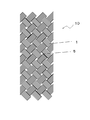
- FIG. 3 is a front view of the braided body stage according to the first embodiment of the present invention, and the longitudinal direction is the vertical direction of the drawing.
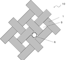
- FIG. 4 is an enlarged view of the weave at the braided body stage according to the first embodiment of the present invention. An inscribed circle is shown in the gap.
- FIG. 5 is a drawing showing an external appearance photograph of Example 1 of the present invention.
- the weave refers to a space between fibers of a fabric.
- the fiber is a bundle (strand), it shows between strands.
- the voids constitute the texture.
- the CVD ceramic layer refers to a ceramic layer formed by a CVD method.
- the tubular body of the present invention comprises a base material composed of a cylindrical braid made of ceramic fibers and a ceramic fired body layer filled between the ceramic fibers, and a CVD ceramic layer covering the surface of the base material.
- the tubular braided body of the present invention is a string made by combining yarns, and is a hollow string because it is woven in a tubular shape.
- a woven fabric in which warp yarns and weft yarns obliquely intersect each other is formed.
- the CVD ceramic layer may be formed on either the inside or the outside of the tubular body, but is preferably formed on both the inside and the outside. A tubular body with higher strength can be obtained by being formed on both sides.
- the ceramic fiber of the tubular body of the present invention is not particularly limited, and examples thereof include SiC fiber, TaC fiber, WC fiber, carbon fiber, TaN fiber, and titanium silicon carbide fiber.
- the ceramic fired body of the tubular body of the present invention is not particularly limited as long as it is a ceramic obtained by firing.
- a ceramic fired body obtained by firing a ceramic precursor made of resin, or a ceramic sintered body fired by adding a sintering aid to ceramic powder may be used.
- the ceramic precursor include polycarbosilane, polyorganoborosilazane, polymetalloxane, polyborosiloxane, and polycarbosilazane.
- SiC from polycarbosilane SiNBC ceramic from polyorganoborosilazane
- Oxide ceramic from polymetalloxane B-Si-CN ceramic from polyorganoborosilazane
- Polycarbosilazane makes it possible to obtain Si—CN—ceramics.
- the CVD ceramic layer of the tubular body of the present invention covers the surface of a base material composed of a cylindrical braided body made of ceramic fibers and a ceramic fired body layer filled between the ceramic fibers. Since the CVD ceramic layer is formed by chemical vapor deposition, it becomes a dense and high-strength film. According to the tubular body of the present invention, a base material composed of a cylindrical braid body made of ceramic fibers and a ceramic fired body layer filled between the ceramic fibers, and a CVD ceramic layer covering the surface of the base material. Therefore, a ceramic / ceramic composite material can be formed and a tough tubular body can be obtained.
- the ceramic fired body layer is filled between the ceramic fibers, the ceramic fired body layer is thin when the ceramic fibers are woven even if the braid has a thin portion such as a weave. Since the portion is intensively filled, a tubular body having a smooth surface with a thin thickness and no weak portion can be obtained. Furthermore, since the ceramic fired body layer can fix the fibers before being put in the CVD furnace, when heated in the CVD furnace, the fibers are not easily broken due to a difference in thermal expansion or the like, and can be made difficult to generate fuzz. A CVD ceramic layer can be reliably deposited.
- the ceramic fiber of the tubular body of the present invention is preferably a SiC fiber.
- a tubular body having high strength and high heat resistance can be obtained by using it as a ceramic fiber of the tubular body.
- the ceramic fiber of the tubular body of the present invention may have a fiber coating layer having a composition different from that of the ceramic fiber on the surface.
- the fiber coating layer include pyrolytic carbon and BN. Even if the ceramic fibers are coated in advance, they can be coated after the weaving process. Since the fiber coating layer is formed at the interface between the ceramic fired body layer and the ceramic fiber, the stress can be dispersed so that cracks extending from the ceramic fired body layer or the CVD ceramic layer are not transmitted to the SiC fiber. For this reason, a high intensity
- the CVD ceramic layer of the tubular body of the present invention is preferably a CVD-SiC layer.
- a tubular body having high strength and high heat resistance can be obtained by using it as a CVD-SiC layer of the tubular body.
- the ceramic fired body layer of the tubular body of the present invention is a SiC fired body layer.
- the SiC fired body layer has heat resistance and high strength, a tubular body having high strength and high heat resistance can be obtained by using it as a ceramic fired body layer of a tubular body.
- the ceramic fiber of the tubular body of the present invention preferably has a fiber diameter of 5 to 20 ⁇ m.
- the fiber diameter of the SiC fiber is 5 ⁇ m or more, the influence of defects such as minute scratches generated on the fiber surface can be reduced, and it can be made difficult to break.
- the fiber diameter of the SiC fiber is 20 ⁇ m or less, it is possible to suppress the tension generated on the outer surface on the side extending along with the bending, and to make it difficult to break.
- the braided cord body of the present invention is preferably formed by weaving the strands of the ceramic fibers.
- the ceramic fiber can be flexibly bent by using a plurality of fine fibers in the form of a bundle in which a plurality of thin fibers are bundled, and the occurrence of fuzz can be prevented. Further, since the ceramic fibers can be rearranged, the cross-sectional shape of the strand can be freely changed. By transforming the strand into a thin band shape, the texture can be prevented from becoming too large, and a smooth surface tubular body can be obtained.
- the number of ceramic fibers constituting the strand is preferably 100 to 10,000. When the number of ceramic fibers constituting the strand is 100 or more, the ceramic fibers can be easily rearranged when the strand is bent, and can be easily deformed into a thin band shape that is not easily subjected to bending stress.
- the ceramic fibers constituting the strand When the number of ceramic fibers constituting the strand is 10,000 or less, the ceramic fibers can be easily rearranged when the strand is bent, and can be easily deformed into a thin band shape that is not easily subjected to bending stress.
- the braided body of the tubular body of the present invention preferably has voids in the weave.
- the tubular body of the present invention has a gap in the weave of the braided body, so that the distance between the ceramic fibers can be widened and the bending of the ceramic fibers in contact with the weave can be made gentle, and the bending stress applied to the ceramic fibers can be reduced.
- a high-strength tubular body that can be reduced in size and has no fluff can be obtained.
- the diameter of the inscribed circle of the void of the weave of the tubular braided body of the present invention is preferably 0.1 to 5 mm.
- the tubular body of the present invention when the inscribed circle of the void of the braid of the braided body constituting the tubular body is 0.1 mm or more, the spacing between the ceramic fibers is widened, and the bending of the fibers in contact with the weave is moderated. Therefore, the bending stress applied to the ceramic fiber can be reduced, and a high-strength tubular body free from fluff can be obtained.
- the tubular body of the present invention can reduce the undulation of the surface of the tubular body caused by the weave when the inscribed circle of the void of the weave of the braided body constituting the tubular body is 5 mm or less, the ceramic By filling the fired body layer, it is possible to obtain a tubular body having a smooth surface with a thin thickness and no weak portions.
- a more desirable range of the diameter of the inscribed circle in the voids of the weave of the tubular braided body of the present invention is 0.2 to 2 mm.
- the tubular body of the present invention when the inscribed circle of the void of the braid of the braided body constituting the tubular body is 0.2 mm or more, the spacing between the ceramic fibers is further widened, and the bending of the fibers in contact with the weave is moderated. Therefore, the bending stress applied to the ceramic fiber can be reduced, and a high-strength tubular body free from fuzz can be obtained.
- the tubular body of the present invention can further reduce the undulation of the surface of the tubular body due to the texture when the inscribed circle of the void of the texture of the braided body constituting the tubular body is 2 mm or less, By filling the ceramic fired body layer, it is possible to obtain a tubular body having a smooth surface with a small thickness and no weak portions.
- the ceramic fired body layer of the tubular body of the present invention preferably contains aggregate.
- the ceramic fired body layer can be efficiently filled into the depressions of the braided body by including the aggregate in the ceramic fired body layer. This is because by containing an aggregate in the ceramic fired body layer, shrinkage during production can be kept small, and the ability to eliminate the dent is great. Therefore, a smooth surface tubular body can be obtained.
- the aggregate include ceramic particles. Specific examples include SiC, WC, zirconia, magnesia, alumina, silica, cordierite and the like, and are not particularly limited.
- the tubular body of the present invention is preferably for nuclear power.
- the tubular body of the present invention is composed of a ceramic / ceramic composite material, has heat resistance, and has high strength, so that it is suitable for nuclear power such as a fuel cladding tube and a channel box for storing nuclear fuel. Can be used.
- the method for manufacturing a tubular body of the present invention for solving the above problems includes a weaving step of weaving ceramic fibers and manufacturing a tubular braided body, and applying a ceramic precursor to the braided body, followed by firing.
- the base material manufacturing process which seals the texture of the braided body by the above, and the CVD process of covering the base material with a CVD ceramic layer and manufacturing a tubular body.
- the braided body in the method for producing a tubular body of the present invention is a string made by combining yarns, and is a hollow string because it is woven into a tubular shape.
- a woven fabric in which warp yarns and weft yarns obliquely intersect each other is formed.
- the ceramic fiber of the tubular body of this invention For example, SiC fiber, TaC fiber, WC fiber, carbon fiber, TaN fiber, titanium silicon carbide fiber, etc. are mentioned.
- the ceramic fired body in the method for producing a tubular body of the present invention is not particularly limited as long as it is a ceramic obtained by firing.
- a ceramic fired body obtained by firing a ceramic precursor made of resin, or a ceramic sintered body fired by adding a sintering aid to ceramic powder may be used.
- the ceramic precursor examples include polycarbosilane, polyorganoborosilazane, polymetalloxane, polyborosiloxane, and polycarbosilazane.
- SiC from polycarbosilane
- SiNBC from polyorganoborosilazane
- Oxide ceramic from polymetalloxane
- B-Si-CN ceramic from polyorganoborosilazane
- Polycarbosilazane Makes it possible to obtain Si—CN—ceramics.
- the CVD ceramic layer covers the surface of a base material composed of a cylindrical braid body made of ceramic fibers and a ceramic fired body layer filling between the ceramic fibers. Since the CVD ceramic layer is formed by chemical vapor deposition, it becomes a dense and high-strength film.
- the braided body is coated with a ceramic precursor and then fired.
- a base material manufacturing process for sealing the weave Therefore, before the CVD ceramic layer is formed in the CVD process, even if there is a thin portion such as a texture, the ceramic precursor is concentrated in the thin portion, and the texture of the braided body is Since sealing is performed, a tubular body having a smooth surface can be produced. Furthermore, since the ceramic fired body layer can fix the fibers before being put in the CVD furnace, when heated in the CVD furnace, the fibers are not easily broken due to a difference in thermal expansion or the like, and can be made difficult to generate fuzz. A CVD ceramic layer can be reliably deposited.
- Calcination can be performed at 800 to 2000 ° C., for example.
- the ceramic fiber in the method for producing a tubular body of the present invention is preferably a SiC fiber.
- a tubular body having high strength and high heat resistance can be produced by using it as a ceramic fiber of the tubular body.
- the ceramic fiber of the method for producing a tubular body of the present invention may have a fiber coating layer having a composition different from that of the ceramic fiber on the surface.
- the fiber coating layer include pyrolytic carbon and BN. Even if the ceramic fibers are coated in advance, they can be coated after the weaving process. Since the fiber coating layer is formed at the interface between the ceramic fired body layer and the ceramic fiber, the stress can be dispersed so that cracks extending from the ceramic fired body layer or the CVD ceramic layer are not transmitted to the SiC fiber. For this reason, a high intensity
- the CVD step of the tubular body manufacturing method of the present invention is preferably a SiC CVD step.
- a high strength and high heat resistance tubular body can be produced by chemical vapor deposition (CVD) of SiC.
- the ceramic precursor of the method for producing a tubular body of the present invention is preferably a SiC precursor.
- the SiC fired body layer obtained by firing the SiC precursor has heat resistance and high strength. Therefore, by firing the SiC precursor and using it as a ceramic fired body layer of a tubular body, high strength and heat resistance are obtained. Can be obtained.
- the SiC precursor is an organic silicon resin such as polycarbosilane.
- the ceramic fiber of the method for producing a tubular body of the present invention preferably has a fiber diameter of 5 to 20 ⁇ m.
- the fiber diameter of the SiC fiber is 5 ⁇ m or more, the influence of defects such as minute scratches generated on the fiber surface can be reduced, and it can be made difficult to break.
- the fiber diameter of the SiC fiber is 20 ⁇ m or less, it is possible to suppress the tension generated on the outer surface on the side extending along with the bending, and to make it difficult to break.
- the braided body of the tubular body manufacturing method of the present invention is preferably formed by weaving strands of ceramic fibers.
- Ceramic fibers can be bent flexibly and prevented from fuzzing by using in the form of a strand in which a plurality of thin fibers are bundled. Further, since the ceramic fibers can be rearranged, the cross-sectional shape of the strand can be freely changed. By transforming the strand into a thin band shape, the texture can be prevented from becoming too large, and a smooth surface tubular body can be obtained.
- the number of ceramic fibers constituting the strand is preferably 100 to 10,000.
- the ceramic fibers can be easily rearranged when the strand is bent, and can be easily deformed into a thin band shape in which bending stress is not easily affected.
- the number of ceramic fibers constituting the strand is 10,000 or less, the ceramic fibers can be easily rearranged when the strand is bent, and can be easily deformed into a thin band shape that is not easily subjected to bending stress.
- the braided body of the method for producing a tubular body of the present invention preferably has voids in the texture.
- the bending of the ceramic fiber in contact with the weave can be made gentle by producing the braid with a void in the weave of the braided body, and the bending stress applied to the ceramic fiber is reduced.
- a small and high-strength tubular body can be produced.
- the diameter of the inscribed circle of the void in the method for producing a tubular body of the present invention is preferably 0.1 to 5 mm.
- the method for manufacturing a tubular body according to the present invention when the inscribed circle of the void of the braid of the braided body constituting the tubular body is 0.1 mm or more, the method of bending the fiber in contact with the weave can be moderated. Therefore, the bending stress applied to the ceramic fiber can be reduced, and a high-strength tubular body can be manufactured.
- the tubular body manufacturing method of the present invention can reduce the undulation of the surface of the tubular body caused by the weave when the inscribed circle of the void of the weave of the braided body constituting the tubular body is 5 mm or less. Therefore, by filling the ceramic fired body layer, it is possible to produce a tubular body having a smooth surface without a thin portion having a thin thickness.
- a more desirable range of the diameter of the inscribed circle in the voids of the weave of the tubular braided body of the present invention is 0.2 to 2 mm.
- the tubular body of the present invention when the inscribed circle of the void of the braid of the braided body constituting the tubular body is 0.2 mm or more, the spacing between the ceramic fibers is further widened, and the bending of the fibers in contact with the weave is moderated. Therefore, the bending stress applied to the ceramic fiber can be reduced, and a high-strength tubular body free from fuzz can be obtained.
- the tubular body of the present invention can further reduce the undulation of the surface of the tubular body due to the texture when the inscribed circle of the void of the texture of the braided body constituting the tubular body is 2 mm or less, By filling the ceramic fired body layer, it is possible to obtain a tubular body having a smooth surface with a small thickness and no weak portions.
- the ceramic precursor of the method for producing a tubular body of the present invention preferably contains an aggregate.
- the ceramic fired body layer can be efficiently filled into the recesses of the braided body by including the aggregate in the ceramic fired body layer. This is because by containing an aggregate in the ceramic fired body layer, shrinkage during production can be kept small, and the ability to eliminate the dent is great. Therefore, a smooth surface tubular body can be obtained.
- the aggregate include ceramic particles. Specific examples include SiC, WC, zirconia, magnesia, alumina, silica, cordierite and the like, and are not particularly limited.
- the tubular body of the present invention is preferably for nuclear power.
- the tubular body of the present invention is composed of a ceramic / ceramic composite material, has heat resistance, and has high strength, so that it is suitable for nuclear power such as a fuel cladding tube and a channel box for storing nuclear fuel. Can be used.
- FIG. 1 shows a process flow of Example 1 of the present invention.
- FIG. 2 shows a cross section of the tubular body of Example 1 of the present invention, with the top of the figure showing the outside of the tubular body and the bottom of the figure showing the inside of the tubular body.
- FIG. 3 is a front view of the braided body stage according to the first embodiment of the present invention, and the longitudinal direction is the vertical direction of the drawing.
- FIG. 4 is an enlarged view of the weave at the braided body stage according to the first embodiment of the present invention. An inscribed circle is shown in the gap.
- FIG. 5 is a drawing showing an external appearance photograph of Example 1 of the present invention.
- the ceramic fiber 1 was a SiC fiber.
- the ceramic fiber was used in the form of a strand in which 1600 SiC fibers “Tyranno SA3” manufactured by Ube Industries, Ltd. having a fiber diameter of 7.5 ⁇ m were bundled.
- a braided body having an inner diameter of 10 mm and a length of 400 mm was obtained from 64 strands using a braiding apparatus.
- FIG. 1 (b) A round bar made of graphite having a diameter of 10 mm was inserted into the braid obtained, and polycarbosilane as a ceramic precursor was applied. Furthermore, after baking with a round bar made of graphite at 1200 ° C., the round bar of graphite was extracted to obtain a substrate. The obtained ceramic fired body layer 2 is SiC.
- FIG. 1 (c) The obtained base material was put in a CVD furnace, and silane gas and methane were introduced as source gases to form a CVD ceramic layer.
- the CVD ceramic layer is a CVD-SiC layer because silane gas and methane are used as source gases.
- the film forming temperature of CVD is 1200 ° C.
- FIG. 2 shows a cross section of the tubular body 100 according to the first embodiment of the present invention, and the upper side of the figure shows the outside of the tubular body 100 and the lower side of the figure shows the inside of the tubular body 100.
- FIG. 3 is a front view of the tubular body 100 according to the first embodiment of the present invention, and the longitudinal direction is the vertical direction of the drawing.
- FIG. 4 is an enlarged view of the weave of the braided body 10 constituting the tubular body 100 according to the first embodiment of the present invention.
- the texture has a gap 5, and an inscribed circle 6 is shown in the gap 5.
- FIG. 5 is a drawing showing an external appearance photograph of Example 1 of the present invention.
- FIG. 2 is a cross-sectional view taken along one strand of the braided body 10 constituting the tubular body 100.
- the braided body 10 has its strands alternately woven so as to form a plain weave when unfolded. Where the strands intersect, the strands are bent and swapped up and down.
- FIG. 3 is a front view of the braid body stage. Woven with 32 right-hand strands and 32 left-hand strands. There are voids 5 in the weaves where the strands intersect. An explanatory view of the inscribed circle 6 of the gap is shown in FIG. The diameter of the inscribed circle 6 of the gap 5 in the braided body 10 is 0.5 mm.
- FIG. 5 is a drawing showing an appearance photograph of the obtained tubular body 100.
- the outer diameter of the tubular body 100 was ⁇ 11 mm, and the inner diameter was ⁇ 10 mm.
- the obtained tubular body 100 made of the SiC / SiC composite material has no fuzz and has a smooth surface, and the entire surface of the tubular body is covered with a CVD-SiC layer.
- the tubular body of the present invention can be used in various shapes such as a thin long rectangular tube and a thin long cylinder used as a fuel assembly material for nuclear applications.
Landscapes
- Engineering & Computer Science (AREA)
- Chemical & Material Sciences (AREA)
- Physics & Mathematics (AREA)
- Ceramic Engineering (AREA)
- Plasma & Fusion (AREA)
- High Energy & Nuclear Physics (AREA)
- General Engineering & Computer Science (AREA)
- Mechanical Engineering (AREA)
- Inorganic Chemistry (AREA)
- Materials Engineering (AREA)
- Structural Engineering (AREA)
- Organic Chemistry (AREA)
- Laminated Bodies (AREA)
- Braiding, Manufacturing Of Bobbin-Net Or Lace, And Manufacturing Of Nets By Knotting (AREA)
- Ceramic Products (AREA)
Abstract
セラミック繊維を組紐体として用いたセラミック/セラミック複合材であって、製造時の繊維の折れによる欠陥が少なく、高強度で耐熱性を有する高性能な管状体及びその製造方法を提供する。管状体(100)は、セラミック繊維(1)からなる筒状の組紐体(10)とセラミック繊維(1)間を充填するセラミック焼成体層(2)とからなる基材と、基材の表面を覆うCVDセラミック層(3)とからなる。管状体(100)の製造方法は、セラミック繊維(1)を製織し、筒状の組紐体(10)を製造する製織工程と、組紐体(10)にセラミック前駆体を塗布した後、焼成することにより組紐体(10)の織目を封止する基材製造工程と、基材にCVDセラミック層(3)を被覆し管状体(100)を製造するCVD工程と、からなる。
Description
本発明は、セラミック/セラミック複合材からなる管状体及びその製造方法に関する。
SiC/SiC複合材からなる管状体は、高強度のSiC繊維を骨材とし、主にSiCがマトリックスを構成する。SiCは、耐熱性を有するとともに耐酸化性のある素材であるので、C/Cコンポジット(炭素繊維強化炭素複合材)が使用できない酸化雰囲気下で使用できる特徴がある。
特許文献1には、放射線照射等の過酷な条件下においても、耐熱性、強度性および精密加工性に優れるという特性を有するスリーブ(管状体)として、SiC繊維強化SiC複合材料(SiC/SiC)からなる円筒状薄肉スリーブであって、気孔率が40%以下で、かつ、肉厚が5mm以下であることを特徴とする円筒状SiC複合材料スリーブが記載されている。
しかしながら、前記記載のSiC繊維強化SiC複合材料(SiC/SiC複合材)からなる管状体は、弾性率の高いSiC繊維を用いている。SiC繊維などのセラミック繊維は、耐熱性を備え、高強度であることから、放射線照射等の過酷な条件下などでも使用できる特徴はあるものの、セラミック繊維は有機繊維とは異なり弾性率が高く、曲げにより簡単に折れる、毛羽立ちし易いといった問題がある。このため、組紐体を製織し繊維が折れないようセラミック/セラミック複合材を得ることは困難である。
本発明では、前記課題を鑑み、セラミック繊維を組紐体として用いたセラミック/セラミック複合材であって、製造時の繊維の折れによる欠陥が少なく、高強度で耐熱性を有する高性能な管状体及びその製造方法を提供すること目的とする。
本発明では、前記課題を鑑み、セラミック繊維を組紐体として用いたセラミック/セラミック複合材であって、製造時の繊維の折れによる欠陥が少なく、高強度で耐熱性を有する高性能な管状体及びその製造方法を提供すること目的とする。
≪管状体≫
前記課題を解決するための本発明の管状体は、セラミック繊維からなる筒状の組紐体と前記セラミック繊維間を充填するセラミック焼成体層とからなる基材と、前記基材の表面を覆うCVDセラミック層と、からなる。
前記課題を解決するための本発明の管状体は、セラミック繊維からなる筒状の組紐体と前記セラミック繊維間を充填するセラミック焼成体層とからなる基材と、前記基材の表面を覆うCVDセラミック層と、からなる。
本発明の管状体によれば、セラミック繊維からなる筒状の組紐体と前記セラミック繊維間を充填するセラミック焼成体層とからなる基材と、前記基材の表面を覆うCVDセラミック層と、からなるので、セラミック/セラミック複合材を構成し、強靱な管状体を得ることができる。
また、前記セラミック繊維間を充填するセラミック焼成体層を有しているので、セラミック繊維が製織される際、組紐体に織目など厚さが薄い部分があっても、セラミック焼成体層が薄い部分に集中的に充填されるので、肉厚が薄く弱い部分のない平滑な表面の管状体が得られる。さらにCVD炉に入れられる前に、セラミック焼成体層が繊維どうしを固定することができるのでCVD炉内で加熱した際に熱膨張差などにより繊維が折れにくく、毛羽立ちを発生しにくくすることができ、確実にCVDセラミック層を沈着させることができる。
さらに、緻密体であるCVDセラミック層を有しているので、不浸透性が高く高強度の管状体を得ることができる。
また、前記セラミック繊維間を充填するセラミック焼成体層を有しているので、セラミック繊維が製織される際、組紐体に織目など厚さが薄い部分があっても、セラミック焼成体層が薄い部分に集中的に充填されるので、肉厚が薄く弱い部分のない平滑な表面の管状体が得られる。さらにCVD炉に入れられる前に、セラミック焼成体層が繊維どうしを固定することができるのでCVD炉内で加熱した際に熱膨張差などにより繊維が折れにくく、毛羽立ちを発生しにくくすることができ、確実にCVDセラミック層を沈着させることができる。
さらに、緻密体であるCVDセラミック層を有しているので、不浸透性が高く高強度の管状体を得ることができる。
本発明の管状体は、以下の態様であることが好ましい。
(A-1)前記セラミック繊維は、SiC繊維である。
(A-1)前記セラミック繊維は、SiC繊維である。
SiC繊維は、耐熱性を備え、高強度であるので、管状体のセラミック繊維として使用することにより、高強度で耐熱性の高い管状体を得ることができる。
(A-2)前記CVDセラミック層は、CVD-SiC層である。
CVD法で得られた被膜は、耐熱性を備え、高強度であるので、管状体のCVD-SiC層として使用することにより、高強度で耐熱性の高い管状体を得ることができる。
(A-3)前記セラミック焼成体層は、SiC焼成体層である。
SiC焼成体層は、耐熱性を備え、高強度であるので、管状体のセラミック焼成体層として使用することにより、高強度で耐熱性の高い管状体を得ることができる。
(A-4)前記組紐体は、前記セラミック繊維のストランドが製織されてなる。
セラミック繊維は、細い繊維を複数束ねたストランドの形態で使用することにより、しなやかに曲げることができ、毛羽立ちの発生を防ぐことができる。さらに、セラミック繊維は再配列することができるのでストランドの断面形状が自由に変化できる。ストランドは、厚さの薄いバンド状に変形することにより、織目が大きくなりすぎることを防ぐことができ、平滑な表面の管状体を得ることができる。
(A-5)前記組紐体は、織目に空隙を有することを特徴とする。
本発明の管状体は、組紐体の織目に空隙を有することにより、織目に接するセラミック繊維の曲がり方を緩やかにすることができ、セラミック繊維にかかる曲げ応力を小さくでき、毛羽立ちのない高強度の管状体を得ることができる。
(A-6)前記空隙の内接円の直径は、0.1~5mmである。
本発明の管状体は、管状体を構成する組紐体の織目の空隙の内接円が0.1mm以上であると、織目に接する繊維の曲がり方を緩やかにすることができるので、セラミック繊維にかかる曲げ応力を小さくでき、毛羽立ちのない高強度の管状体を得ることができる。
本発明の管状体は、管状体を構成する組紐体の織目の空隙の内接円が5mm以下であると、織目に起因する管状体の表面の起伏を小さくすることができるので、セラミック焼成体層が充填されることにより、肉厚が薄い弱い部分のない平滑な表面の管状体を得ることができる。
本発明の管状体は、管状体を構成する組紐体の織目の空隙の内接円が5mm以下であると、織目に起因する管状体の表面の起伏を小さくすることができるので、セラミック焼成体層が充填されることにより、肉厚が薄い弱い部分のない平滑な表面の管状体を得ることができる。
(A-7)前記セラミック焼成体層は、骨材を含有する。
本発明の管状体は、セラミック焼成体層に、骨材を含有することにより、組紐体の有する凹みに効率良くセラミック焼成体層を充填することができる。これは、セラミック焼成体層に骨材を含有することにより、製造時の収縮を小さく抑えることができ、凹みを解消する能力が大きいからである。このため、平滑な表面の管状体を得ることができる。
(A-8)前記管状体は、原子力用である。
本発明の管状体は、セラミック/セラミック複合材で構成され、耐熱性を有している上に、高い強度を備えているので、原子力燃料を収納するチャンネルボックスなど原子力用として好適に利用することができる。
本発明の管状体は、セラミック/セラミック複合材で構成され、耐熱性を有している上に、高い強度を備えているので、原子力燃料を収納するチャンネルボックスなど原子力用として好適に利用することができる。
≪管状体の製造方法≫
前記課題を解決するための本発明の管状体の製造方法は、セラミック繊維を製織し、筒状の組紐体を製造する製織工程と、前記組紐体にセラミック前駆体を塗布した後、焼成することにより前記組紐体の織目を封止する基材製造工程と、基材にCVDセラミック層を被覆し管状体を製造するCVD工程と、からなる。
前記課題を解決するための本発明の管状体の製造方法は、セラミック繊維を製織し、筒状の組紐体を製造する製織工程と、前記組紐体にセラミック前駆体を塗布した後、焼成することにより前記組紐体の織目を封止する基材製造工程と、基材にCVDセラミック層を被覆し管状体を製造するCVD工程と、からなる。
本発明の管状体の製造方法によれば、セラミック繊維を製織し、筒状の組紐体を製造する製織工程の後に、前記組紐体にセラミック前駆体を塗布した後、焼成することにより前記組紐体の織目を封止する基材製造工程を有している。このため、CVD工程でCVDセラミック層が形成される前に、織目などの厚さが薄い部分があっても、セラミック前駆体が薄い部分に集中的に充填され、前記組紐体の織目を封止するので、平滑な表面の管状体を製造することができる。さらにCVD炉に入れられる前に、セラミック焼成体層が繊維どうしを固定することができるのでCVD炉内で加熱した際に熱膨張差などにより繊維が折れにくく、毛羽立ちを発生しにくくすることができ、確実にCVDセラミック層を沈着させることができる。
さらに、緻密体であるCVDセラミック層を被覆するCVD工程を有しているので、不浸透性が高く高強度の管状体を製造することができる。
(B-1)前記セラミック繊維は、SiC繊維である。
SiC繊維は、耐熱性を備え、高強度であるので、管状体のセラミック繊維として使用することにより、高強度で耐熱性の高い管状体を製造することができる。
(B-2)前記CVD工程は、SiCのCVD工程である。
CVD法で得られた被膜は、耐熱性を備え、高強度であるので、SiCを化学気相成長(CVD)させることにより、高強度で耐熱性の高い管状体を製造することができる。
(B-3)前記セラミック前駆体は、SiC前駆体である。
SiC焼成体層は、耐熱性を備え、高強度であるので、SiC前駆体を焼成し管状体のセラミック焼成体層として使用することにより、高強度で耐熱性の高い管状体を得ることができる。
(B-4)前記組紐体は、前記セラミック繊維のストランドが製織されてなる。
セラミック繊維は、細い繊維を複数束ねたストランドの形態で使用することにより、しなやかに曲げることができ、毛羽立ちの発生を防ぐことができる。さらに、セラミック繊維は再配列することができるのでストランドの断面形状が自由に変化できる。ストランドは、厚さの薄いバンド状に変形することにより、織目が大きくなりすぎることを防ぐことができ、平滑な表面の管状体を得ることができる。
(B-5)前記組紐体は、前記織目に空隙を有する。
本発明の管状体の製造方法では、組紐体の織目に空隙を有するように製造することにより、織目に接するセラミック繊維の曲がり方を緩やかにすることができ、セラミック繊維にかかる曲げ応力を小さくでき高強度の管状体を製造することができる。
(B-6)前記空隙の内接円の直径は、0.1~5mmである。
本発明の管状体の製造方法は、管状体を構成する組紐体の織目の空隙の内接円が0.1mm以上であると、織目に接する繊維の曲がり方を緩やかにすることができるので、セラミック繊維にかかる曲げ応力を小さくでき高強度の管状体を製造することができる。
本発明の管状体の製造方法は、管状体を構成する組紐体の織目の空隙の内接円が5mm以下であると、織目に起因する管状体の表面の起伏を小さくすることができるので、セラミック焼成体層が充填されることにより、薄く弱い部分のない平滑な表面の管状体を製造することができる。
(B-7)前記セラミック前駆体は骨材を含有する。
本発明の管状体の製造方法は、セラミック焼成体層に、骨材を含有することにより、組紐体の有する凹みに効率良くセラミック焼成体層を充填することができる。これは、セラミック焼成体層に骨材を含有することにより、製造時の収縮を小さく抑えることができ、凹みを解消する能力が大きいからである。このため、平滑な表面の管状体を得ることができる。
(B-8)前記管状体は、原子力用である。
本発明から得られる管状体は、セラミック/セラミック複合材で構成され、耐熱性を有している上に、高い強度を備えているので、原子力燃料を収納するチャンネルボックスなど原子力用として好適に利用することができる。
本発明から得られる管状体は、セラミック/セラミック複合材で構成され、耐熱性を有している上に、高い強度を備えているので、原子力燃料を収納するチャンネルボックスなど原子力用として好適に利用することができる。
本発明の管状体によれば、セラミック繊維からなる筒状の組紐体と前記セラミック繊維間を充填するセラミック焼成体層とからなる基材と、前記基材の表面を覆うCVDセラミック層と、からなるので、セラミック/セラミック複合材を構成し、強靱な管状体を得ることができる。
また、前記セラミック繊維間を充填するセラミック焼成体層を有しているので、セラミック繊維が製織される際、組紐体に織目など厚さが薄い部分があっても、セラミック焼成体層が薄い部分に集中的に充填されるので、肉厚が薄く弱い部分のない平滑な表面の管状体が得られる。さらにCVD炉に入れられる前に、セラミック焼成体層が繊維どうしを固定することができるのでCVD炉内で加熱した際に熱膨張差などにより繊維が折れにくく、毛羽立ちを発生しにくくすることができ、確実にCVDセラミック層を沈着させることができる。
さらに、緻密体であるCVDセラミック層を有しているので、不浸透性が高く高強度の管状体を得ることができる。
また、前記セラミック繊維間を充填するセラミック焼成体層を有しているので、セラミック繊維が製織される際、組紐体に織目など厚さが薄い部分があっても、セラミック焼成体層が薄い部分に集中的に充填されるので、肉厚が薄く弱い部分のない平滑な表面の管状体が得られる。さらにCVD炉に入れられる前に、セラミック焼成体層が繊維どうしを固定することができるのでCVD炉内で加熱した際に熱膨張差などにより繊維が折れにくく、毛羽立ちを発生しにくくすることができ、確実にCVDセラミック層を沈着させることができる。
さらに、緻密体であるCVDセラミック層を有しているので、不浸透性が高く高強度の管状体を得ることができる。
本発明の管状体の製造方法によれば、セラミック繊維を製織し、筒状の組紐体を製造する製織工程の後に、前記組紐体にセラミック前駆体を塗布した後、焼成することにより前記組紐体の織目を封止する基材製造工程を有している。このため、CVD工程でCVDセラミック層が形成される前に、織目などの厚さが薄い部分があっても、セラミック前駆体が薄い部分に集中的に充填され、前記組紐体の織目を封止するので、平滑な表面の管状体を製造することができる。さらにCVD炉に入れられる前に、セラミック焼成体層が繊維どうしを固定することができるのでCVD炉内で加熱した際に熱膨張差などにより繊維が折れにくく、毛羽立ちを発生しにくくすることができ、確実にCVDセラミック層を沈着させることができる。
さらに、緻密体であるCVDセラミック層を被覆するCVD工程を有しているので、不浸透性が高く高強度の管状体を製造することができる。
さらに、緻密体であるCVDセラミック層を被覆するCVD工程を有しているので、不浸透性が高く高強度の管状体を製造することができる。
本明細書において、織目とは、織物の繊維と繊維の間をしめす。繊維が束(ストランド)になっている場合には、ストランドとストランドとの間を示す。織目に空隙を有する場合には、その空隙が織目を構成する。
本明細書において、CVDセラミック層とは、CVD法により形成されたセラミック層を示す。
本明細書において、CVDセラミック層とは、CVD法により形成されたセラミック層を示す。
≪管状体≫
本発明の管状体は、セラミック繊維からなる筒状の組紐体と前記セラミック繊維間を充填するセラミック焼成体層とからなる基材と、前記基材の表面を覆うCVDセラミック層と、からなる。
本発明の管状体は、セラミック繊維からなる筒状の組紐体と前記セラミック繊維間を充填するセラミック焼成体層とからなる基材と、前記基材の表面を覆うCVDセラミック層と、からなる。
本発明の管状体の組紐体とは、糸を組み合わせて作った紐であり、管状に製織されているので中空の紐となる。組紐体の中手方向に切れ目を入れて展開すると、例えば縦糸、緯糸がそれぞれ斜めに交差した織布となる。
CVDセラミック層は、管状体の内側及び外側のいずれに形成されていてもよいが、内側及び外側の両側に形成されていることが望ましい。両側に形成されていることでより高強度な管状体を得ることができる。
CVDセラミック層は、管状体の内側及び外側のいずれに形成されていてもよいが、内側及び外側の両側に形成されていることが望ましい。両側に形成されていることでより高強度な管状体を得ることができる。
本発明の管状体のセラミック繊維とは、特に限定されないが例えば、SiC繊維、TaC繊維、WC繊維、炭素繊維、TaN繊維、チタンシリコンカーバイド繊維などが挙げられる。
本発明の管状体のセラミック焼成体とは、焼成されて得られたセラミックであれば良く特に限定されない。例えば、樹脂からなるセラミック前駆体を焼成して得られたセラミック焼成体、セラミックの粉末に焼結助剤を加え焼成したセラミックの焼結体でも良い。
セラミック前駆体としては、ポリカルボシラン、ポリオルガノボロシラザン、ポリメタロキサン、ポリボロシロキサン、ポリカルボシラザンなどが挙げられる。焼成することによりポリカルボシランからはSiC、ポリオルガノボロシラザンからはSiNBCセラミック、ポリメタロキサンからは酸化物系セラミック、ポリオルガノボロシラザンからは、B-Si-C-N系セラミック、ポリカルボシラザンからはSi-C-N系セラミックが得られる。
セラミック前駆体としては、ポリカルボシラン、ポリオルガノボロシラザン、ポリメタロキサン、ポリボロシロキサン、ポリカルボシラザンなどが挙げられる。焼成することによりポリカルボシランからはSiC、ポリオルガノボロシラザンからはSiNBCセラミック、ポリメタロキサンからは酸化物系セラミック、ポリオルガノボロシラザンからは、B-Si-C-N系セラミック、ポリカルボシラザンからはSi-C-N系セラミックが得られる。
本発明の管状体のCVDセラミック層は、セラミック繊維からなる筒状の組紐体とセラミック繊維間を充填するセラミック焼成体層とからなる基材の表面を覆う。CVDセラミック層は、化学気相成長法で形成されるので、緻密で高強度な被膜となる。
本発明の管状体によれば、セラミック繊維からなる筒状の組紐体と前記セラミック繊維間を充填するセラミック焼成体層とからなる基材と、前記基材の表面を覆うCVDセラミック層と、からなるので、セラミック/セラミック複合材を構成し、強靱な管状体を得ることができる。
また、前記セラミック繊維間を充填するセラミック焼成体層を有しているので、セラミック繊維が製織される際、組紐体に織目など厚さが薄い部分があっても、セラミック焼成体層が薄い部分に集中的に充填されるので、肉厚が薄く弱い部分のない平滑な表面の管状体が得られる。さらにCVD炉に入れられる前に、セラミック焼成体層が繊維どうしを固定することができるのでCVD炉内で加熱した際に熱膨張差などにより繊維が折れにくく、毛羽立ちを発生しにくくすることができ、確実にCVDセラミック層を沈着させることができる。
本発明の管状体によれば、セラミック繊維からなる筒状の組紐体と前記セラミック繊維間を充填するセラミック焼成体層とからなる基材と、前記基材の表面を覆うCVDセラミック層と、からなるので、セラミック/セラミック複合材を構成し、強靱な管状体を得ることができる。
また、前記セラミック繊維間を充填するセラミック焼成体層を有しているので、セラミック繊維が製織される際、組紐体に織目など厚さが薄い部分があっても、セラミック焼成体層が薄い部分に集中的に充填されるので、肉厚が薄く弱い部分のない平滑な表面の管状体が得られる。さらにCVD炉に入れられる前に、セラミック焼成体層が繊維どうしを固定することができるのでCVD炉内で加熱した際に熱膨張差などにより繊維が折れにくく、毛羽立ちを発生しにくくすることができ、確実にCVDセラミック層を沈着させることができる。
さらに、緻密体であるCVDセラミック層を有しているので、不浸透性が高く高強度の管状体を得ることができる。
本発明の管状体のセラミック繊維は、SiC繊維であることが好ましい。
SiC繊維は、耐熱性を備え、高強度であるので、管状体のセラミック繊維として使用することにより、高強度で耐熱性の高い管状体を得ることができる。
本発明の管状体のセラミック繊維は、表面にセラミック繊維と組成の異なる繊維被覆層を有していても良い。繊維被覆層としては、熱分解炭素、BNなどが挙げられる。あらかじめセラミック繊維に被覆しておいても、製織工程後に被覆することもできる。繊維被覆層はセラミック焼成体層とセラミック繊維との界面に形成されるので、セラミック焼成体層あるいはCVDセラミック層から伸展するクラックをSiC繊維に伝達しないように応力を分散することができる。このため、高強度の管状体を得ることができる。
本発明の管状体のCVDセラミック層は、CVD-SiC層であることが好ましい。
CVD法で得られた被膜は、耐熱性を備え、高強度であるので、管状体のCVD-SiC層として使用することにより、高強度で耐熱性の高い管状体を得ることができる。
本発明の管状体のセラミック焼成体層は、SiC焼成体層である。
SiC焼成体層は、耐熱性を備え、高強度であるので、管状体のセラミック焼成体層として使用することにより、高強度で耐熱性の高い管状体を得ることができる。
本発明の管状体のセラミック繊維は繊維直径が5~20μmであることが好ましい。
SiC繊維の繊維直径が5μm以上であると繊維表面に発生する微少な傷などの欠陥の影響を小さくすることができ、折れにくくすることができる。SiC繊維の繊維直径が20μm以下であると、曲げに伴って延びる側の外表面に発生する張力を抑制することができ、折れにくくすることができる。
SiC繊維の繊維直径が5μm以上であると繊維表面に発生する微少な傷などの欠陥の影響を小さくすることができ、折れにくくすることができる。SiC繊維の繊維直径が20μm以下であると、曲げに伴って延びる側の外表面に発生する張力を抑制することができ、折れにくくすることができる。
本発明の管状体の組紐体は、前記セラミック繊維のストランドが製織されてなることが好ましい。
セラミック繊維は、細い繊維を複数束ねたストランドの形態で使用することにより、しなやかに曲げることができ、毛羽立ちの発生を防ぐことができる。さらに、セラミック繊維は再配列することができるのでストランドの断面形状が自由に変化できる。ストランドは、厚さの薄いバンド状に変形することにより、織目が大きくなりすぎることを防ぐことができ、平滑な表面の管状体を得ることができる。
ストランドを構成するセラミック繊維の数は100~10000本であることが好ましい。ストランドを構成するセラミック繊維の数が100本以上であると、ストランドを曲げた際にセラミック繊維が自由に再配列しやすく、曲げ応力のかかりにくい薄いバンド状に容易に変形することができる。
ストランドを構成するセラミック繊維の数は100~10000本であることが好ましい。ストランドを構成するセラミック繊維の数が100本以上であると、ストランドを曲げた際にセラミック繊維が自由に再配列しやすく、曲げ応力のかかりにくい薄いバンド状に容易に変形することができる。
ストランドを構成するセラミック繊維の数が10000本以下であると、ストランドを曲げた際にセラミック繊維が自由に再配列しやすく、曲げ応力のかかりにくい薄いバンド状に容易に変形することができる。
本発明の管状体の組紐体は、織目に空隙を有することが好ましい。
本発明の管状体は、組紐体の織目に空隙を有することにより、セラミック繊維どうしの間隔を広げ織目に接するセラミック繊維の曲がり方を緩やかにすることができ、セラミック繊維にかかる曲げ応力を小さくでき、毛羽立ちのない高強度の管状体を得ることができる。
本発明の管状体の組紐体の織目の空隙の内接円の直径は、0.1~5mmであることが好ましい。
本発明の管状体は、管状体を構成する組紐体の織目の空隙の内接円が0.1mm以上であると、セラミック繊維どうしの間隔を広げ織目に接する繊維の曲がり方を緩やかにすることができるので、セラミック繊維にかかる曲げ応力を小さくでき、毛羽立ちのない高強度の管状体を得ることができる。
本発明の管状体は、管状体を構成する組紐体の織目の空隙の内接円が5mm以下であると、織目に起因する管状体の表面の起伏を小さくすることができるので、セラミック焼成体層が充填されることにより、肉厚が薄く弱い部分のない平滑な表面の管状体を得ることができる。
本発明の管状体は、管状体を構成する組紐体の織目の空隙の内接円が5mm以下であると、織目に起因する管状体の表面の起伏を小さくすることができるので、セラミック焼成体層が充填されることにより、肉厚が薄く弱い部分のない平滑な表面の管状体を得ることができる。
本発明の管状体の組紐体の織目の空隙の内接円の直径のさらに望ましい範囲は、0.2~2mmである。
本発明の管状体は、管状体を構成する組紐体の織目の空隙の内接円が0.2mm以上であると、セラミック繊維どうしの間隔をさらに広げ織目に接する繊維の曲がり方を緩やかにすることができるので、セラミック繊維にかかる曲げ応力を小さくでき、毛羽立ちのない高強度の管状体を得ることができる。
本発明の管状体は、管状体を構成する組紐体の織目の空隙の内接円が2mm以下であると、織目に起因する管状体の表面の起伏をさらに小さくすることができるので、セラミック焼成体層が充填されることにより、肉厚が薄く弱い部分のない平滑な表面の管状体を得ることができる。
本発明の管状体は、管状体を構成する組紐体の織目の空隙の内接円が2mm以下であると、織目に起因する管状体の表面の起伏をさらに小さくすることができるので、セラミック焼成体層が充填されることにより、肉厚が薄く弱い部分のない平滑な表面の管状体を得ることができる。
本発明の管状体のセラミック焼成体層は、骨材を含有することが好ましい。
本発明の管状体は、セラミック焼成体層に、骨材を含有することにより、組紐体の有する凹みに効率良くセラミック焼成体層を充填することができる。これは、セラミック焼成体層に骨材を含有することにより、製造時の収縮を小さく抑えることができ、凹みを解消する能力が大きいからである。このため、平滑な表面の管状体を得ることができる。
骨材としては、セラミックの粒子などが挙げられる。具体的には、SiC、WC、ジルコニア、マグネシア、アルミナ、シリカ、コージェライトなどが挙げられ特に限定されない。
骨材としては、セラミックの粒子などが挙げられる。具体的には、SiC、WC、ジルコニア、マグネシア、アルミナ、シリカ、コージェライトなどが挙げられ特に限定されない。
本発明の管状体は、原子力用であることが好ましい。
本発明の管状体は、セラミック/セラミック複合材で構成され、耐熱性を有している上に、高い強度を備えているので、原子力燃料を収納する燃料被覆管、チャンネルボックスなど原子力用として好適に利用することができる。このような管状体を用いることにより、炉内が高温に曝されても、冷却水との反応を抑え、水素ガスの発生を防止することができる。
本発明の管状体は、セラミック/セラミック複合材で構成され、耐熱性を有している上に、高い強度を備えているので、原子力燃料を収納する燃料被覆管、チャンネルボックスなど原子力用として好適に利用することができる。このような管状体を用いることにより、炉内が高温に曝されても、冷却水との反応を抑え、水素ガスの発生を防止することができる。
≪管状体の製造方法≫
前記課題を解決するための本発明の管状体の製造方法は、セラミック繊維を製織し、筒状の組紐体を製造する製織工程と、前記組紐体にセラミック前駆体を塗布した後、焼成することにより前記組紐体の織目を封止する基材製造工程と、基材にCVDセラミック層を被覆し管状体を製造するCVD工程と、からなる。
前記課題を解決するための本発明の管状体の製造方法は、セラミック繊維を製織し、筒状の組紐体を製造する製織工程と、前記組紐体にセラミック前駆体を塗布した後、焼成することにより前記組紐体の織目を封止する基材製造工程と、基材にCVDセラミック層を被覆し管状体を製造するCVD工程と、からなる。
本発明の管状体の製造方法の組紐体とは、糸を組み合わせて作った紐であり、管状に製織されているので中空の紐となる。組紐体の中手方向に切れ目を入れて展開すると、例えば縦糸、緯糸がそれぞれ斜めに交差した織布となる。
本発明の管状体のセラミック繊維とは、特に限定されないが例えば、SiC繊維、TaC繊維、WC繊維、炭素繊維、TaN繊維、チタンシリコンカーバイド繊維などが挙げられる。
本発明の管状体のセラミック繊維とは、特に限定されないが例えば、SiC繊維、TaC繊維、WC繊維、炭素繊維、TaN繊維、チタンシリコンカーバイド繊維などが挙げられる。
本発明の管状体の製造方法のセラミック焼成体とは、焼成されて得られたセラミックであれば良く特に限定されない。例えば、樹脂からなるセラミック前駆体を焼成して得られたセラミック焼成体、セラミックの粉末に焼結助剤を加え焼成したセラミックの焼結体でも良い。
セラミック前駆体としては、ポリカルボシラン、ポリオルガノボロシラザン、ポリメタロキサン、ポリボロシロキサン、ポリカルボシラザンなどが挙げられる。焼成することによりポリカルボシランからはSiC、ポリオルガノボロシラザンからはSiNBCセラミック、ポリメタロキサンからは酸化物系セラミック、ポリオルガノボロシラザンからは、B-Si-C-N系セラミック、ポリカルボシラザンからはSi-C-N系セラミックが得られる。
本発明の管状体の製造方法のCVD工程では、CVDセラミック層がセラミック繊維からなる筒状の組紐体とセラミック繊維間を充填するセラミック焼成体層とからなる基材の表面を覆う。CVDセラミック層は、化学気相成長法で形成されるので、緻密で高強度な被膜となる。
本発明の管状体の製造方法のCVD工程では、CVDセラミック層がセラミック繊維からなる筒状の組紐体とセラミック繊維間を充填するセラミック焼成体層とからなる基材の表面を覆う。CVDセラミック層は、化学気相成長法で形成されるので、緻密で高強度な被膜となる。
本発明の管状体の製造方法によれば、セラミック繊維を製織し、筒状の組紐体を製造する製織工程の後に、前記組紐体にセラミック前駆体を塗布した後、焼成することにより前記組紐体の織目を封止する基材製造工程を有している。このため、CVD工程でCVDセラミック層が形成される前に、織目などの厚さが薄い部分があっても、セラミック前駆体が薄い部分に集中的に充填され、前記組紐体の織目を封止するので、平滑な表面の管状体を製造することができる。さらにCVD炉に入れられる前に、セラミック焼成体層が繊維どうしを固定することができるのでCVD炉内で加熱した際に熱膨張差などにより繊維が折れにくく、毛羽立ちを発生しにくくすることができ、確実にCVDセラミック層を沈着させることができる。
さらに、緻密体であるCVDセラミック層を被覆するCVD工程を有しているので、不浸透性が高く高強度の管状体を製造することができる。
焼成は、例えば800~2000℃で処理することができる。
本発明の管状体の製造方法のセラミック繊維は、SiC繊維であることが好ましい。
SiC繊維は、耐熱性を備え、高強度であるので、管状体のセラミック繊維として使用することにより、高強度で耐熱性の高い管状体を製造することができる。
本発明の管状体の製造方法のセラミック繊維は、表面にセラミック繊維と組成の異なる繊維被覆層を有していても良い。繊維被覆層としては、熱分解炭素、BNなどが挙げられる。あらかじめセラミック繊維に被覆しておいても、製織工程後に被覆することもできる。繊維被覆層はセラミック焼成体層とセラミック繊維との界面に形成されるので、セラミック焼成体層あるいはCVDセラミック層から伸展するクラックをSiC繊維に伝達しないように応力を分散することができる。このため、高強度の管状体を得ることができる。
本発明の管状体の製造方法のCVD工程は、SiCのCVD工程であることが好ましい。
CVD法で得られた被膜は、耐熱性を備え、高強度であるので、SiCを化学気相成長(CVD)させることにより、高強度で耐熱性の高い管状体を製造することができる。
本発明の管状体の製造方法のセラミック前駆体は、SiC前駆体であることが好ましい。
SiC前駆体を焼成して得られるSiC焼成体層は、耐熱性を備え、高強度であるので、SiC前駆体を焼成し管状体のセラミック焼成体層として使用することにより、高強度で耐熱性の高い管状体を得ることができる。SiC前駆体は、例えばポリカルボシランなどの有機珪素樹脂である。
本発明の管状体製造方法のセラミック繊維は繊維直径が5~20μmであることが好ましい。
SiC繊維の繊維直径が5μm以上であると繊維表面に発生する微少な傷などの欠陥の影響を小さくすることができ、折れにくくすることができる。SiC繊維の繊維直径が20μm以下であると、曲げに伴って延びる側の外表面に発生する張力を抑制することができ、折れにくくすることができる。
SiC繊維の繊維直径が5μm以上であると繊維表面に発生する微少な傷などの欠陥の影響を小さくすることができ、折れにくくすることができる。SiC繊維の繊維直径が20μm以下であると、曲げに伴って延びる側の外表面に発生する張力を抑制することができ、折れにくくすることができる。
本発明の管状体の製造方法の組紐体は、セラミック繊維のストランドが製織されてなることが好ましい。
セラミック繊維は、細い繊維を複数束ねたストランドの形態で使用することにより、しなやかに曲げることができ、毛羽立ちの発生を防ぐことができる。さらに、セラミック繊維は再配列することができるのでストランドの断面形状が自由に変化できる。ストランドは、厚さの薄いバンド状に変形することにより、織目が大きくなりすぎることを防ぐことができ、平滑な表面の管状体を得ることができる。
ストランドを構成するセラミック繊維の数は100~10000本であることが好ましい。ストランドを構成するセラミック繊維の数が100本以上であると、ストランドを曲げた際にセラミック繊維が自由に再配列しやすく、曲げ応力の係りにくい薄いバンド状に容易に変形することができる。
ストランドを構成するセラミック繊維の数が10000本以下であると、ストランドを曲げた際にセラミック繊維が自由に再配列しやすく、曲げ応力のかかりにくい薄いバンド状に容易に変形することができる。
ストランドを構成するセラミック繊維の数が10000本以下であると、ストランドを曲げた際にセラミック繊維が自由に再配列しやすく、曲げ応力のかかりにくい薄いバンド状に容易に変形することができる。
本発明の管状体の製造方法の組紐体は、織目に空隙を有することが好ましい。
本発明の管状体の製造方法では、組紐体の織目に空隙を有するように製造することにより、織目に接するセラミック繊維の曲がり方を緩やかにすることができ、セラミック繊維にかかる曲げ応力を小さくでき高強度の管状体を製造することができる。
本発明の管状体の製造方法の空隙の内接円の直径は、0.1~5mmであることが好ましい。
本発明の管状体の製造方法は、管状体を構成する組紐体の織目の空隙の内接円が0.1mm以上であると、織目に接する繊維の曲がり方を緩やかにすることができるので、セラミック繊維にかかる曲げ応力を小さくでき高強度の管状体を製造することができる。
本発明の管状体の製造方法は、管状体を構成する組紐体の織目の空隙の内接円が5mm以下であると、織目に起因する管状体の表面の起伏を小さくすることができるので、セラミック焼成体層が充填されることにより、肉厚が薄い弱い部分のない平滑な表面の管状体を製造することができる。
本発明の管状体の製造方法は、管状体を構成する組紐体の織目の空隙の内接円が5mm以下であると、織目に起因する管状体の表面の起伏を小さくすることができるので、セラミック焼成体層が充填されることにより、肉厚が薄い弱い部分のない平滑な表面の管状体を製造することができる。
本発明の管状体の組紐体の織目の空隙の内接円の直径のさらに望ましい範囲は、0.2~2mmである。
本発明の管状体は、管状体を構成する組紐体の織目の空隙の内接円が0.2mm以上であると、セラミック繊維どうしの間隔をさらに広げ織目に接する繊維の曲がり方を緩やかにすることができるので、セラミック繊維にかかる曲げ応力を小さくでき、毛羽立ちのない高強度の管状体を得ることができる。
本発明の管状体は、管状体を構成する組紐体の織目の空隙の内接円が2mm以下であると、織目に起因する管状体の表面の起伏をさらに小さくすることができるので、セラミック焼成体層が充填されることにより、肉厚が薄く弱い部分のない平滑な表面の管状体を得ることができる。
本発明の管状体は、管状体を構成する組紐体の織目の空隙の内接円が2mm以下であると、織目に起因する管状体の表面の起伏をさらに小さくすることができるので、セラミック焼成体層が充填されることにより、肉厚が薄く弱い部分のない平滑な表面の管状体を得ることができる。
本発明の管状体の製造方法のセラミック前駆体は骨材を含有することが好ましい。
本発明の管状体の製造方法は、セラミック焼成体層に、骨材を含有することにより、組紐体の有する凹みに効率良くセラミック焼成体層を充填することができる。これは、セラミック焼成体層に骨材を含有することにより、製造時の収縮を小さく抑えることができ、凹みを解消する能力が大きいからである。このため、平滑な表面の管状体を得ることができる。
骨材としては、セラミックの粒子などが挙げられる。具体的には、SiC、WC、ジルコニア、マグネシア、アルミナ、シリカ、コージェライトなどが挙げられ特に限定されない。
骨材としては、セラミックの粒子などが挙げられる。具体的には、SiC、WC、ジルコニア、マグネシア、アルミナ、シリカ、コージェライトなどが挙げられ特に限定されない。
本発明の管状体は、原子力用であることが好ましい。
本発明の管状体は、セラミック/セラミック複合材で構成され、耐熱性を有している上に、高い強度を備えているので、原子力燃料を収納する燃料被覆管、チャンネルボックスなど原子力用として好適に利用することができる。このような管状体を用いることにより、炉内が高温に曝されても、冷却水との反応を抑え、水素ガスの発生を防止することができる。
本発明の管状体は、セラミック/セラミック複合材で構成され、耐熱性を有している上に、高い強度を備えているので、原子力燃料を収納する燃料被覆管、チャンネルボックスなど原子力用として好適に利用することができる。このような管状体を用いることにより、炉内が高温に曝されても、冷却水との反応を抑え、水素ガスの発生を防止することができる。
以下本発明の実施例について図を用いて説明する。図1は、本発明の実施例1の工程フローを示す。図2は、本発明の実施例1の管状体の断面を示し、図の上が管状体の外側、図の下が管状体の内側を示す。図3は、本発明の実施例1の組紐体段階の正面図であり、長手方向が図の上下方向である。図4は、本発明の実施例1の組紐体段階の織目の拡大図である。空隙には、内接円が図示されている。図5は、本発明の実施例1の外観写真を表す図面である。
本発明の管状体及びその製造方法について、実施例1を用いて順に説明する。
<製織工程>図1(a)
セラミック繊維1はSiC繊維を用いた。セラミック繊維は、繊維直径7.5μmの宇部興産株式会社製SiC繊維「チラノSA3」を1600本束ねたストランドの形態で使用した。64本のストランドを、ブレーディング装置を用い、内径φ10mm、長さ400mmの組紐体を得た。
セラミック繊維1はSiC繊維を用いた。セラミック繊維は、繊維直径7.5μmの宇部興産株式会社製SiC繊維「チラノSA3」を1600本束ねたストランドの形態で使用した。64本のストランドを、ブレーディング装置を用い、内径φ10mm、長さ400mmの組紐体を得た。
<基材製造工程>図1(b)
得られた組紐体に、φ10mmの黒鉛製の丸棒を挿入し、セラミック前駆体であるポリカルボシランを塗布した。さらに黒鉛製の丸棒とともに1200℃で焼成したのち、黒鉛の丸棒を抜き取り、基材を得た。得られたセラミック焼成体層2は、SiCである。
得られた組紐体に、φ10mmの黒鉛製の丸棒を挿入し、セラミック前駆体であるポリカルボシランを塗布した。さらに黒鉛製の丸棒とともに1200℃で焼成したのち、黒鉛の丸棒を抜き取り、基材を得た。得られたセラミック焼成体層2は、SiCである。
<CVD工程>図1(c)
得られた基材をCVD炉に入れ、シランガス及びメタンを原料ガスとして導入し、CVDセラミック層を形成した。CVDセラミック層はシランガス及びメタンを原料ガスとしたので、CVD-SiC層である。CVDの成膜温度は、1200℃である。
以上の工程により、セラミック繊維1がSiC繊維、セラミック焼成体層2がSiC焼成体層、CVDセラミック層3がCVD-SiC層である断面が円形の管状体が得られた。
得られた基材をCVD炉に入れ、シランガス及びメタンを原料ガスとして導入し、CVDセラミック層を形成した。CVDセラミック層はシランガス及びメタンを原料ガスとしたので、CVD-SiC層である。CVDの成膜温度は、1200℃である。
以上の工程により、セラミック繊維1がSiC繊維、セラミック焼成体層2がSiC焼成体層、CVDセラミック層3がCVD-SiC層である断面が円形の管状体が得られた。
次に得られた管状体100について説明する。図2は、本発明の実施例1の管状体100の断面を示し、図の上が管状体100の外側、図の下が管状体100の内側を示す。図3は、本発明の実施例1の管状体100の正面図であり、長手方向が図の上下方向である。図4は、本発明の実施例1の管状体100を構成する組紐体10の織目の拡大図である。織目には空隙5を有し、空隙5には、内接円6が図示されている。図5は、本発明の実施例1の外観写真を表す図面である。
図2は、管状体100を構成する組紐体10のある1本のストランドに沿って切断した断面図である。組紐体10は、展開すると平織りとなるようにストランドが交互に織られている。ストランドが交差する箇所では、ストランドは曲げられ上下に入れ替わっている。
図3は、組紐体段階の正面図である。右回りストランド32本、左周りのストランド32本により製織されている。ストランドの交差する織目には、空隙5を有している。
空隙の内接円6の説明図を、図4に示す。組紐体10における空隙5の内接円6の直径は0.5mmである。図5は得られた管状体100の外観写真を表す図面である。管状体100の外径はφ11mm、内径はφ10mmであった。得られたSiC/SiC複合材よりなる管状体100は、毛羽立ちはなく、平滑な表面が得られ管状体の表面全体がCVD-SiC層により覆われている。
図3は、組紐体段階の正面図である。右回りストランド32本、左周りのストランド32本により製織されている。ストランドの交差する織目には、空隙5を有している。
空隙の内接円6の説明図を、図4に示す。組紐体10における空隙5の内接円6の直径は0.5mmである。図5は得られた管状体100の外観写真を表す図面である。管状体100の外径はφ11mm、内径はφ10mmであった。得られたSiC/SiC複合材よりなる管状体100は、毛羽立ちはなく、平滑な表面が得られ管状体の表面全体がCVD-SiC層により覆われている。
<性能評価>
得られた実施例1の管状体を100mmの長さに切断し1200℃に加熱し、水中投下したが、クラック、割れは発生しなかった。
得られた実施例1の管状体を100mmの長さに切断し1200℃に加熱し、水中投下したが、クラック、割れは発生しなかった。
<比較例>
SiC粉末を原料とし、押出成形、焼結して得たSiC焼結体を用い、同様に水中投下試験を実施した。長さ150mm、内径10mm外径φ12mmのSiCパイプを同様に1200℃に加熱し、水中に透過したところ、バラバラに割れた。
比較例1のSiC焼結体よりなる管状体と、実施例1のSiC/SiC複合材よりなる管状体とを比較し、本発明によれば高強度の管状体を得ることができることが確認された。
SiC粉末を原料とし、押出成形、焼結して得たSiC焼結体を用い、同様に水中投下試験を実施した。長さ150mm、内径10mm外径φ12mmのSiCパイプを同様に1200℃に加熱し、水中に透過したところ、バラバラに割れた。
比較例1のSiC焼結体よりなる管状体と、実施例1のSiC/SiC複合材よりなる管状体とを比較し、本発明によれば高強度の管状体を得ることができることが確認された。
本出願は、2014年7月9日出願の日本国特許出願(特願2014-141329)に基づくものであり、それらの内容はここに参照として取り込まれる。
本発明の管状体は、原子力用途の燃料集合体材料にとして用いられる薄肉長尺角筒、薄肉長尺円筒などの様々な形状にも利用することができる。
1 セラミック繊維
2 セラミック焼成体層
3 CVDセラミック層
5 空隙
6 内接円
10 組紐体
100 管状体
2 セラミック焼成体層
3 CVDセラミック層
5 空隙
6 内接円
10 組紐体
100 管状体
Claims (18)
- セラミック繊維からなる筒状の組紐体と前記セラミック繊維間を充填するセラミック焼成体層とからなる基材と、
前記基材の表面を覆うCVDセラミック層と、
からなることを特徴とする管状体。 - 前記セラミック繊維は、SiC繊維であることを特徴とする請求項1に記載の管状体。
- 前記CVDセラミック層は、CVD-SiC層であることを特徴とする請求項1または請求項2に記載の管状体。
- 前記セラミック焼成体層は、SiC焼成体層であることを特徴とする請求項1~請求項3のうちのいずれか1項に記載の管状体。
- 前記組紐体は、前記セラミック繊維のストランドが製織されてなることを特徴とする請求項1~請求項4のうちのいずれか1項に記載の管状体。
- 前記組紐体は、織目に空隙を有することを特徴とする請求項1~請求項5のうちのいずれか1項に記載の管状体。
- 前記空隙の内接円の直径は、0.1~5mmであることを特徴とする請求項6に記載の管状体。
- 前記セラミック焼成体層は、骨材を含有することを特徴とする請求項1~請求項7のうちのいずれか1項に記載の管状体。
- 前記管状体は、原子力用であることを特徴とする請求項1~請求項8のうちのいずれか1項に記載の管状体。
- セラミック繊維を製織し、筒状の組紐体を製造する製織工程と、
前記組紐体にセラミック前駆体を塗布した後、焼成することにより前記組紐体の織目を封止する基材製造工程と、
基材にCVDセラミック層を被覆し管状体を製造するCVD工程と、
からなることを特徴とする管状体の製造方法。 - 前記セラミック繊維は、SiC繊維であることを特徴とする請求項10に記載の管状体の製造方法。
- 前記CVD工程は、SiCのCVD工程であることを特徴とする請求項10または請求項11に記載の管状体の製造方法。
- 前記セラミック前駆体は、SiC前駆体であることを特徴とする請求項10~請求項12のうちのいずれか1項に記載の管状体の製造方法。
- 前記組紐体は、前記セラミック繊維のストランドが製織されてなることを特徴とする請求項10~請求項13のうちのいずれか1項に記載の管状体の製造方法。
- 前記組紐体は、前記織目に空隙を有することを特徴とする請求項10~請求項14のうちのいずれか1項に記載の管状体の製造方法。
- 前記空隙の内接円の直径は、0.1~5mmであることを特徴とする請求項15に記載の管状体の製造方法。
- 前記セラミック前駆体は骨材を含有することを特徴とする請求項10~請求項16のうちのいずれか1項に記載の管状体の製造方法。
- 前記管状体は、原子力用であることを特徴とする請求項10~請求項17のうちのいずれか1項に記載の管状体の製造方法。
Applications Claiming Priority (2)
| Application Number | Priority Date | Filing Date | Title |
|---|---|---|---|
| JP2014-141329 | 2014-07-09 | ||
| JP2014141329A JP6490915B2 (ja) | 2014-07-09 | 2014-07-09 | 管状体及びその製造方法 |
Publications (1)
| Publication Number | Publication Date |
|---|---|
| WO2016006668A1 true WO2016006668A1 (ja) | 2016-01-14 |
Family
ID=55064296
Family Applications (1)
| Application Number | Title | Priority Date | Filing Date |
|---|---|---|---|
| PCT/JP2015/069805 Ceased WO2016006668A1 (ja) | 2014-07-09 | 2015-07-09 | 管状体及びその製造方法 |
Country Status (2)
| Country | Link |
|---|---|
| JP (1) | JP6490915B2 (ja) |
| WO (1) | WO2016006668A1 (ja) |
Cited By (1)
| Publication number | Priority date | Publication date | Assignee | Title |
|---|---|---|---|---|
| WO2016076354A1 (ja) * | 2014-11-11 | 2016-05-19 | イビデン株式会社 | 流体用整流部材 |
Families Citing this family (3)
| Publication number | Priority date | Publication date | Assignee | Title |
|---|---|---|---|---|
| US10446276B2 (en) * | 2016-06-21 | 2019-10-15 | Westinghouse Electric Company Llc | Method of manufacturing a SiC composite fuel cladding with inner Zr alloy liner |
| JP6975594B2 (ja) * | 2017-09-19 | 2021-12-01 | 三菱重工業株式会社 | 耐せん断高耐熱性無機繊維結合型セラミックス製のロッド形状部品及びその製造方法 |
| JP6868601B2 (ja) | 2018-11-01 | 2021-05-12 | 株式会社フェローテックマテリアルテクノロジーズ | SiC繊維を内包する管状体およびその製造方法 |
Citations (3)
| Publication number | Priority date | Publication date | Assignee | Title |
|---|---|---|---|---|
| US5182077A (en) * | 1991-04-15 | 1993-01-26 | Gamma Engineering Corporation | Water cooled nuclear reactor and fuel elements therefor |
| JP2008501977A (ja) * | 2004-06-07 | 2008-01-24 | ウエスチングハウス・エレクトリック・カンパニー・エルエルシー | 原子力発電所における燃料格納容器障壁等に使用される多層セラミックチューブ |
| JP2013210372A (ja) * | 2013-04-26 | 2013-10-10 | Ibiden Co Ltd | 核燃料被覆管及びその製造方法 |
-
2014
- 2014-07-09 JP JP2014141329A patent/JP6490915B2/ja active Active
-
2015
- 2015-07-09 WO PCT/JP2015/069805 patent/WO2016006668A1/ja not_active Ceased
Patent Citations (3)
| Publication number | Priority date | Publication date | Assignee | Title |
|---|---|---|---|---|
| US5182077A (en) * | 1991-04-15 | 1993-01-26 | Gamma Engineering Corporation | Water cooled nuclear reactor and fuel elements therefor |
| JP2008501977A (ja) * | 2004-06-07 | 2008-01-24 | ウエスチングハウス・エレクトリック・カンパニー・エルエルシー | 原子力発電所における燃料格納容器障壁等に使用される多層セラミックチューブ |
| JP2013210372A (ja) * | 2013-04-26 | 2013-10-10 | Ibiden Co Ltd | 核燃料被覆管及びその製造方法 |
Non-Patent Citations (2)
| Title |
|---|
| FEINROTH, HERBERT ET AL.: "Progress in Developing an Impermeable, High Temperature Ceramic Composite for Advanced Reactor Clad And Structual Applications", ICAPP'02: 2002 INTERNATIONAL CONGRESS ON ADVANCES IN NUCLEAR POWER PLANTS, June 2002 (2002-06-01), ISBN: 0-89448-663-2 * |
| LORRETTE C. ET AL.: "PROGRESS IN DEVELOPING SIC/SIC COMPOSITEMATERIALS FOR ADVANCED NUCLEAR REACTORS", 18TH INTERNATIONAL CONFERENCE ON COMPOSITE MATERIALS, INTERNATIONAL COMMITTEE ON COMPOSITE MATERIALS, August 2011 (2011-08-01), Retrieved from the Internet <URL:http://www.iccm-central.org/Proceedings/IccMl8proceedings/data/2.%200ral%20Presentation/Aug25%28Thursday%29/Th05%20Carbon%20and%20Ceramic%20Matrix%20Composites/Th05-4-IF2017.pdf> * |
Cited By (1)
| Publication number | Priority date | Publication date | Assignee | Title |
|---|---|---|---|---|
| WO2016076354A1 (ja) * | 2014-11-11 | 2016-05-19 | イビデン株式会社 | 流体用整流部材 |
Also Published As
| Publication number | Publication date |
|---|---|
| JP6490915B2 (ja) | 2019-03-27 |
| JP2016016603A (ja) | 2016-02-01 |
Similar Documents
| Publication | Publication Date | Title |
|---|---|---|
| JP5696174B2 (ja) | 核燃料被覆管及びその製造方法 | |
| KR101089971B1 (ko) | 관형체 및 그 제조 방법 | |
| JP6490915B2 (ja) | 管状体及びその製造方法 | |
| RU2617298C2 (ru) | Волокнистая армирующая структура для изделия из композитного материала, имеющего участок уменьшенной толщины | |
| JP5539386B2 (ja) | セラミック繊維の処理方法 | |
| WO2016093360A1 (ja) | 炭化ケイ素繊維強化炭化ケイ素複合材料 | |
| JP6334293B2 (ja) | 管状体 | |
| JP6334292B2 (ja) | 管状体の製造方法 | |
| CN108863418A (zh) | 长纤维增强碳化硅构件、其制造方法及核反应堆结构构件 | |
| KR101623914B1 (ko) | 균일한 미세구조를 가지는 탄화규소 섬유강화 탄화규소 복합체(SiCf/SiC)의 제조방법 | |
| JP2003252694A (ja) | SiC繊維複合化SiC複合材料 | |
| JP6460808B2 (ja) | 管状体 | |
| JP2017024923A (ja) | セラミック複合材 | |
| JP2018095508A (ja) | SiC繊維強化SiC複合材料の製造方法 | |
| WO2015016072A1 (ja) | セラミック複合材料及びセラミック複合材料の製造方法 | |
| JP6719333B2 (ja) | 長繊維強化炭化ケイ素部材、および、その製造方法 | |
| JP7343360B2 (ja) | セラミック複合材及びその製造方法 | |
| JP6122728B2 (ja) | SiC繊維強化SiC複合材料及びSiC繊維強化SiC複合材料の製造方法 | |
| JP2017145181A (ja) | SiC/SiC複合材料の製造方法 | |
| JP4616442B2 (ja) | 耐酸化保護層を有する炭素質材料およびその製造方法 | |
| CN109996774A (zh) | 包含铝掺杂氮化硼的中间相层的复合材料部件 | |
| JP5870652B2 (ja) | 被膜付きセラミックス基複合材料およびその製造方法 | |
| JP2021129835A (ja) | 固定具 |
Legal Events
| Date | Code | Title | Description |
|---|---|---|---|
| 121 | Ep: the epo has been informed by wipo that ep was designated in this application |
Ref document number: 15819537 Country of ref document: EP Kind code of ref document: A1 |
|
| NENP | Non-entry into the national phase |
Ref country code: DE |
|
| 122 | Ep: pct application non-entry in european phase |
Ref document number: 15819537 Country of ref document: EP Kind code of ref document: A1 |