WO2016006417A1 - 送り装置及びそれを用いた加工装置 - Google Patents
送り装置及びそれを用いた加工装置 Download PDFInfo
- Publication number
- WO2016006417A1 WO2016006417A1 PCT/JP2015/067763 JP2015067763W WO2016006417A1 WO 2016006417 A1 WO2016006417 A1 WO 2016006417A1 JP 2015067763 W JP2015067763 W JP 2015067763W WO 2016006417 A1 WO2016006417 A1 WO 2016006417A1
- Authority
- WO
- WIPO (PCT)
- Prior art keywords
- workpiece
- processing
- switching valve
- sensor
- supply passage
- Prior art date
- Legal status (The legal status is an assumption and is not a legal conclusion. Google has not performed a legal analysis and makes no representation as to the accuracy of the status listed.)
- Ceased
Links
Images


Classifications
-
- A—HUMAN NECESSITIES
- A47—FURNITURE; DOMESTIC ARTICLES OR APPLIANCES; COFFEE MILLS; SPICE MILLS; SUCTION CLEANERS IN GENERAL
- A47J—KITCHEN EQUIPMENT; COFFEE MILLS; SPICE MILLS; APPARATUS FOR MAKING BEVERAGES
- A47J43/00—Implements for preparing or holding food, not provided for in other groups of this subclass
- A47J43/04—Machines for domestic use not covered elsewhere, e.g. for grinding, mixing, stirring, kneading, emulsifying, whipping or beating foodstuffs, e.g. power-driven
- A47J43/07—Parts or details, e.g. mixing tools, whipping tools
-
- A—HUMAN NECESSITIES
- A47—FURNITURE; DOMESTIC ARTICLES OR APPLIANCES; COFFEE MILLS; SPICE MILLS; SUCTION CLEANERS IN GENERAL
- A47J—KITCHEN EQUIPMENT; COFFEE MILLS; SPICE MILLS; APPARATUS FOR MAKING BEVERAGES
- A47J43/00—Implements for preparing or holding food, not provided for in other groups of this subclass
- A47J43/20—Shapes for preparing foodstuffs, e.g. meat-patty moulding devices, pudding moulds
-
- B—PERFORMING OPERATIONS; TRANSPORTING
- B26—HAND CUTTING TOOLS; CUTTING; SEVERING
- B26D—CUTTING; DETAILS COMMON TO MACHINES FOR PERFORATING, PUNCHING, CUTTING-OUT, STAMPING-OUT OR SEVERING
- B26D3/00—Cutting work characterised by the nature of the cut made; Apparatus therefor
- B26D3/28—Splitting layers from work; Mutually separating layers by cutting
-
- B—PERFORMING OPERATIONS; TRANSPORTING
- B26—HAND CUTTING TOOLS; CUTTING; SEVERING
- B26D—CUTTING; DETAILS COMMON TO MACHINES FOR PERFORATING, PUNCHING, CUTTING-OUT, STAMPING-OUT OR SEVERING
- B26D7/00—Details of apparatus for cutting, cutting-out, stamping-out, punching, perforating, or severing by means other than cutting
- B26D7/06—Arrangements for feeding or delivering work of other than sheet, web, or filamentary form
Definitions
- the present invention relates to a feeding device and a processing device using the same.
- JP 2009-172683A discloses a slicer that cuts block meat formed into a predetermined shape into a predetermined thickness.
- a screw rod that is rotationally driven by a servo motor moves a pusher to feed block meat, and the fed block meat is cut by a rotating blade.
- the slicer described in JP2009-172683A feeds block meat using a servo motor. Therefore, feedback control is generally executed based on the position of the pusher detected by a potentiometer, an encoder, or the like in order to accurately cut the block meat into a predetermined thickness.
- An object of the present invention is to provide a feeding device that can accurately feed a workpiece with a simple configuration.
- a feed device that feeds a workpiece by a predetermined amount, a water pressure source that supplies compressed working water, and a pressure chamber that is supplied with working water from the water pressure source through a supply passage. And a piston rod that is pushed out together with the piston by the working water supplied to the pressure chamber, and is provided in the supply passage, and provided in the supply passage, for a time corresponding to the feed amount of the workpiece. And a switching valve that switches the supply passage to an open state and switches to a closed state when the time has elapsed.
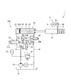
- FIG. 1 is a configuration diagram of a feeding device and a processing device using the same according to an embodiment of the present invention.
- FIG. 2 is a diagram illustrating a state in which the blade portion has reached the processing start position of the workpiece.
- FIG. 3 is a diagram illustrating a state in which the blade portion has passed the processing end position of the workpiece.
- a configuration of a feeding device 100 according to an embodiment of the present invention and a processing device 1 using the same will be described.
- a case will be described in which a block meat 9 having a constant cross-sectional area is used as a workpiece, and the machining performed by the machining apparatus 1 is cutting the block meat 9.
- the processing apparatus 1 uses the feeding apparatus 100 to intermittently cut the block meat 9 into the same thickness.
- the processing apparatus 1 includes a feeding device 100 that intermittently feeds the block meat 9 by a predetermined amount, a rotating cutter 2 as a processing mechanism that cuts the block meat 9 sent by the feeding device 100 at a constant period, and a rotating cutter 2.
- the first sensor 5 (see FIGS. 2 and 3) for detecting that the cutting of the block meat 9 is started, and the second sensor 6 (FIG. 2) for detecting that the rotary cutter 2 has finished cutting the block meat 9. And FIG. 3).
- the rotary cutter 2 includes a blade portion 3 that rotates at a constant speed to cut the block meat 9 and an electric motor 4 that rotationally drives the blade portion 3.
- the rotary cutter 2 cuts the block meat 9 fed out by a cylinder 20 described later of the feeding device 100 at a constant cycle.
- the blade portion 3 has an arcuate cutting portion 3 a formed so as to protrude toward the block meat 9.
- the blade portion 3 rotates at a constant speed around the rotation shaft 3b.
- the blade part 3 cuts the block meat 9 vertically.
- the electric motor 4 has a rotating shaft 4a connected to the rotating shaft 3b of the blade portion 3 as shown in FIG.
- the electric motor 4 generates sufficient torque so that the rotation speed does not change even when the blade 3 cuts the block meat 9.
- the first sensor 5 is provided facing the processing start position of the block meat 9 as shown in FIGS.
- the first sensor 5 is a non-contact sensor that detects that the blade portion 3 reaches the block meat 9.
- the second sensor 6 is provided facing the processing end position of the block meat 9.
- the second sensor 6 is a non-contact sensor that detects that the blade portion 3 has passed the block meat 9.
- the first sensor 5 and the second sensor 6 are, for example, optical proximity sensors that can detect that the blade portion 3 is located in a detectable region.
- machining start position is the position of the blade portion 3 where the cutting of the block meat 9 is started (see FIG. 2).
- processing end position is the position of the blade portion 3 that has completely passed through the cut block meat 9 (see FIG. 3). Further, “cutting is completed” means that the blade portion 3 has completely passed through the cut block meat 9.
- the processing device 1 is based on an electrical signal output from the first sensor 5 and an electrical signal output from the second sensor 6, and will be described later, a first switching valve 31, a second switching valve 32, and a third switching valve. 33 and a controller (not shown) for controlling the opening and closing of the fourth switching valve 34.
- a controller not shown for controlling the opening and closing of the fourth switching valve 34.
- an opening / closing mechanism for mechanically opening and closing the first switching valve 31, the second switching valve 32, the third switching valve 33, and the fourth switching valve 34 is provided so as to synchronize with the operation of the rotary cutter 2. Also good.
- the feeding device 100 includes a water pressure pump 10 as a water pressure source for supplying compressed working water, and a cylinder 20 that expands and contracts by working water supplied from the water pressure pump 10 through a supply passage 12.
- the water pressure pump 10 sucks and discharges the working water stored in the tank 13.
- the hydraulic pump 10 is rotationally driven at a constant speed by the electric motor 11.
- the cylinder 20 includes a piston side chamber 21 as a pressure chamber to which working water discharged from the hydraulic pump 10 is supplied, a piston rod 24 pushed out together with the piston 23 by the working water supplied to the piston side chamber 21, and a piston rod 24. And a rod side chamber 22 to be inserted.
- the cylinder 20 sends out the block meat 9 by the piston rod 24 withdrawing.
- a seal member 23 a is provided on the outer periphery of the piston 23. Therefore, the working water in the piston side chamber 21 is prevented from leaking into the rod side chamber 22 from between the outer periphery of the piston 23 and the inner periphery of the cylinder 20.
- the feeding device 100 is configured such that the first switching valve 31 serving as a switching valve that switches the supply passage 12 to an open state for a time corresponding to the feed amount of the block meat 9 and the first switching valve 31 are simultaneously switched to the opened state.
- a second switching valve 32 that is switched to the open state, and a third switching valve 33 and a fourth switching valve 34 that are switched to the open state when the piston rod 24 is returned into the cylinder 20 are provided.
- the first switching valve 31 is provided in the supply passage 12. In the normal state, the first switching valve 31 is maintained in the closed state by the biasing force of the return spring 31b. When a control current is supplied to the solenoid 31a, the urging force of the solenoid 31a overcomes the urging force of the return spring 31b and the first switching valve 31 is switched to the open state.
- the first switching valve 31 switches the supply passage 12 to the closed state while the rotary cutter 2 is cutting the block meat 9 in accordance with the electrical signals from the first sensor 5 and the second sensor 6, and the rotary cutter 2 However, the supply passage 12 is switched to the open state only while the block meat 9 is not cut.
- a control current is supplied to the solenoid 31a only after the second sensor 6 no longer detects the blade 3 until the first sensor 5 detects the blade 3.
- the first switching valve 31 is provided in the supply passage 12 only for the time from when the second sensor 6 detects the end of processing of the block meat 9 until the first sensor 5 detects the start of processing of the block meat 9. Switch to the open state.
- the second switching valve 32 is provided in the return passage 14 that communicates the rod side chamber 22 of the cylinder 20 and the tank 13. In the normal state, the second switching valve 32 is maintained in the closed state by the urging force of the return spring 32b. When the control current is supplied to the solenoid 32a, the urging force of the solenoid 32a overcomes the urging force of the return spring 32b and the second switching valve 32 is switched to the open state. The second switching valve 32 is switched to the open state only while the first switching valve 31 is switched to the open state.
- the third switching valve 33 and the fourth switching valve 34 are switched to the open state when the piston rod 24 enters the cylinder after the block meat 9 has been cut.
- the third switching valve 33 and the fourth switching valve 34 are always kept closed during the operation of cutting the block meat 9.
- both the first switching valve 31 and the second switching valve 32 are switched to the closed state.
- the third switching valve 33 is provided in the first cross passage 17 that connects the rod side chamber 22 of the cylinder 20 and the supply passage 12.
- the first cross passage 17 is connected to the supply passage 12 upstream of the first switching valve 31.
- the third switching valve 33 is kept closed by the urging force of the return spring 33b.
- the fourth switching valve 34 is provided in the second cross passage 18 that connects the piston side chamber 21 of the cylinder 20 and the return passage 14.
- the second cross passage 18 is connected to the return passage 14 downstream of the second switching valve 32.
- the fourth switching valve 34 is kept closed by the urging force of the return spring 34b.
- the feeding device 100 includes an accumulator 15 that absorbs pulsation of working water discharged from the hydraulic pump 10 and a relief valve 16 that maintains the pressure of working water in the supply passage 12 at a set pressure or less.
- the block meat 9 is set in advance at the tip of the piston rod 24. At this time, the tip end of the block meat 9 is in contact with the blade portion 3 or at a position away from the blade portion 3.
- the controller switches to the solenoid 31 a of the first switching valve 31.
- a control current is supplied.
- the first switching valve 31 is switched to an open state by the urging force of the solenoid 31a and allows the flow of working water in the supply passage 12.
- the second switching valve 32 is similarly switched to the open state.
- the working water discharged from the hydraulic pump 10 is supplied to the piston-side chamber 21 of the cylinder 20, and the piston 23 moves by the amount of the working water.
- the piston rod 24 is retracted from the cylinder 20, and the block meat 9 is sent out by a fixed amount by the piston rod 24.
- the control current is not supplied from the controller to the solenoid 31a of the first switching valve 31.
- the first switching valve 31 is switched to the closed state by the urging force of the return spring 31b, and the flow of the working water in the supply passage 12 is blocked.
- the second switching valve 32 is similarly switched to the closed state.
- the cross-sectional area A [m 2 ] of the piston 23 is constant.
- the movement amount ⁇ x [m] of the piston 23 is the same as the displacement amount when the piston rod 24 expands and contracts. Therefore, the displacement amount [m] when the piston rod 24 expands and contracts changes only by the time ⁇ t [s] if the flow rate Q p [m 3 / s] of the working water discharged from the hydraulic pump 10 is constant. To do. Accordingly, when the rotary cutter 2 rotates at a constant period, the time ⁇ t [s] is constant, and therefore the displacement amount [m] of the piston rod 24 in each period is constant.
- the block meat 9 When the block meat 9 is intermittently sent out by a predetermined amount and reaches a position where it can be cut by the blade portion 3, the block meat 9 is cut to a predetermined thickness by the blade portion 3 while the movement is stopped. In this way, the block meat 9 is fed out while the first switching valve 31 is switched to the open state, and is predetermined by the blade portion 3 while the first switching valve 31 is switched to the closed state and stopped moving. Is cut into thickness.
- the block meat 9 is intermittently cut to the same thickness.
- the working water has a larger volume modulus of elasticity than other working fluids such as working oil, bubbles are hardly mixed, and there is almost no change in viscosity due to temperature. Therefore, by using the working water, the block meat 9 can be sent out by a predetermined amount corresponding to the flow rate of the working water more accurately than when other working fluid is used. Therefore, since it is not necessary to perform feedback control by using the working water, it is possible to feed the block meat 9 accurately with a simple configuration and cut it intermittently to the same thickness. As described above, the feeding device 100 can perform control with high repeatability without performing feedback control.
- the block meat 9 can be intermittently cut to the same thickness only by opening / closing control of the first switching valve 31, so there is no possibility of occurrence of overshoot or vibration. Therefore, it is easy to operate in synchronization with other devices.
- the piston rod 24 is returned into the cylinder 20 by the operation of the operator. Specifically, the first switching valve 31 and the second switching valve 32 are switched to the closed state, and the third switching valve 33 and the fourth switching valve 34 are switched to the open state. As a result, the working water discharged from the hydraulic pump 10 is supplied to the rod side chamber 22 of the cylinder 20, and the working water in the piston side chamber 21 is returned to the tank 13. Therefore, since the piston rod 24 enters the cylinder 20, a new block meat 9 can be set at the tip of the piston rod 24.
- the working water with a constant flow rate is supplied to the piston side chamber 21 according to the time when the first switching valve 31 is switched to the open state, and the piston rod 24 intermittently pushes out the block meat 9. Since the hydraulic water has a larger bulk modulus than other hydraulic fluids such as hydraulic fluid, the block meat 9 is sent out by a predetermined amount according to the flow rate of the hydraulic water more accurately than when other hydraulic fluids are used. be able to. Therefore, since it is not necessary to perform feedback control by using working water, it is possible to feed the block meat 9 accurately with a simple configuration and cut it intermittently to the same thickness.
- the controller may control the opening and closing of the first switching valve 31 based on an output signal from a stroke sensor (not shown) that detects the stroke amount of the piston rod 24 or the like.
- the controller may control the opening and closing of the first switching valve 31 based on an output signal from a rotation angle sensor (not shown) that detects the rotation angle of the electric motor 4 that rotates the blade portion 3.
- the rotary cutter 2 is used.
- a cutter that reciprocates up and down with respect to the workpiece may be used.
- a pair of sensors or a sensor and a timer may be used.
Landscapes
- Engineering & Computer Science (AREA)
- Mechanical Engineering (AREA)
- Food Science & Technology (AREA)
- Life Sciences & Earth Sciences (AREA)
- Forests & Forestry (AREA)
- Details Of Cutting Devices (AREA)
- Food-Manufacturing Devices (AREA)
- Crushing And Pulverization Processes (AREA)
Abstract
送り装置(100)は、圧縮された作動水を供給する水圧源(10)と、水圧源(10)から供給通路(12)を通じて作動水が供給される圧力室(21)と、圧力室(21)に供給される作動水によってピストン(23)とともに押し出されるピストンロッド(23)と、を有し、被加工物(9)を送り出すシリンダ(20)と、被加工物(9)の送り量に応じた時間だけ供給通路(12)を開状態に切り換え当該時間が経過すると閉状態に切り換える切換弁(31)と、を備える。
Description
本発明は、送り装置及びそれを用いた加工装置に関するものである。
従来から、食品などの被加工物を連続して同一の厚さに切断する加工装置が用いられている。
JP2009-172683Aには、所定形状に成形されたブロック肉を所定の厚さに切断するスライサが開示されている。このスライサでは、サーボモータにて回転駆動されるネジロッドがプッシャーを移動させることによってブロック肉を送り出し、送り出された厚さのブロック肉を回転する刃物によって切断している。
JP2009-172683Aに記載のスライサは、サーボモータを用いてブロック肉を送り出すものである。そのため、ブロック肉を正確に所定の厚さに切断するために、ポテンショメータやエンコーダなどによって検出したプッシャーの位置に基づいてフィードバック制御が実行されるのが一般的である。
本発明は、簡素な構成で正確に被加工物を送り出すことが可能な送り装置を提供することを目的とする。
本発明のある態様によれば、被加工物を所定量だけ送り出す送り装置であって、圧縮された作動水を供給する水圧源と、前記水圧源から供給通路を通じて作動水が供給される圧力室と、当該圧力室に供給される作動水によってピストンとともに押し出されるピストンロッドと、を有し、被加工物を送り出すシリンダと、前記供給通路に設けられ、被加工物の送り量に応じた時間だけ前記供給通路を開状態に切り換え当該時間が経過すると閉状態に切り換える切換弁と、を備えることを特徴とする。
以下、図面を参照して、本発明の実施の形態について説明する。
まず、図1から図3を参照して、本発明の実施の形態に係る送り装置100及びそれを用いた加工装置1の構成について説明する。本実施の形態では、被加工物として断面積が一定のブロック肉9が用いられ、加工装置1が実行する加工がブロック肉9の切断である場合について説明する。
加工装置1は、送り装置100を用いてブロック肉9を間歇的に同一の厚さに切断するものである。加工装置1は、ブロック肉9を間歇的に所定量ずつ送り出す送り装置100と、送り装置100によって送り出されたブロック肉9を一定の周期で切断する加工機構としての回転カッタ2と、回転カッタ2がブロック肉9の切断を開始することを検出する第一センサ5(図2及び図3参照)と、回転カッタ2がブロック肉9の切断を終了したことを検出する第二センサ6(図2及び図3参照)と、を備える。
回転カッタ2は、一定の速度で回転してブロック肉9を切断する刃部3と、刃部3を回転駆動する電動モータ4と、を備える。回転カッタ2は、送り装置100の後述するシリンダ20によって送り出されたブロック肉9を一定の周期で切断する。
刃部3は、図2及び図3に示すように、ブロック肉9に向かって凸に形成される円弧状の切断部3aを有する。刃部3は、回転軸3bを中心に一定の速度で回転する。刃部3は、ブロック肉9を垂直に切断する。
電動モータ4は、図1に示すように、刃部3の回転軸3bに連結される回転軸4aを有する。電動モータ4は、刃部3がブロック肉9を切断しても回転速度が変わらない程度の充分なトルクを発生する。
第一センサ5は、図2及び図3に示すように、ブロック肉9の加工開始位置に臨んで設けられる。第一センサ5は、刃部3がブロック肉9に差し掛かることを検出する非接触センサである。第二センサ6は、ブロック肉9の加工終了位置に臨んで設けられる。第二センサ6は、刃部3がブロック肉9を通過したことを検出する非接触センサである。第一センサ5及び第二センサ6は、例えば、検出可能な領域に刃部3が位置していることを検出可能な光学式の近接センサである。
ここで、「加工開始位置」とは、ブロック肉9の切断を開始する刃部3の位置(図2参照)である。「加工終了位置」とは、切断したブロック肉9を完全に通過した刃部3の位置(図3参照)である。また、「切断が終了した」とは、切断したブロック肉9を刃部3が完全に通過したことをいう。
また、加工装置1は、第一センサ5から出力される電気信号と第二センサ6から出力される電気信号とに基づいて後述する第一切換弁31,第二切換弁32,第三切換弁33,及び第四切換弁34を開閉制御するコントローラ(図示省略)を備える。コントローラに代えて、回転カッタ2の動作と同期するように第一切換弁31,第二切換弁32,第三切換弁33,及び第四切換弁34を機械的に開閉する開閉機構を設けてもよい。
次に、送り装置100の構成について説明する。
送り装置100は、圧縮された作動水を供給する水圧源としての水圧ポンプ10と、水圧ポンプ10から供給通路12を通じて供給される作動水によって伸縮するシリンダ20と、を備える。
水圧ポンプ10は、タンク13に溜められた作動水を吸い込んで吐出する。水圧ポンプ10は、電動モータ11によって一定の速度に回転駆動される。
シリンダ20は、水圧ポンプ10から吐出される作動水が供給される圧力室としてのピストン側室21と、ピストン側室21に供給される作動水によってピストン23とともに押し出されるピストンロッド24と、ピストンロッド24が挿通するロッド側室22と、を有する。シリンダ20は、ピストン側室21に作動水が供給されると、ピストンロッド24が退出することによってブロック肉9を送り出す。
ピストン23の外周には、シール部材23aが設けられる。よって、ピストン側室21内の作動水がピストン23の外周とシリンダ20の内周との間からロッド側室22に漏れることが防止される。
送り装置100は、ブロック肉9の送り量に応じた時間だけ供給通路12を開状態に切り換える切換弁としての第一切換弁31と、第一切換弁31が開状態に切り換えられたときに同時に開状態に切り換えられる第二切換弁32と、ピストンロッド24をシリンダ20内に戻すときに開状態に切り換えられる第三切換弁33及び第四切換弁34と、を備える。
第一切換弁31は、供給通路12に設けられる。第一切換弁31は、通常の状態では、戻しばね31bの付勢力によって閉状態に維持される。第一切換弁31は、ソレノイド31aに制御電流が供給されると、ソレノイド31aの付勢力が戻しばね31bの付勢力に打ち勝って開状態に切り換えられる。第一切換弁31は、第一センサ5及び第二センサ6からの電気信号に応じて、回転カッタ2がブロック肉9を切断している間は供給通路12を閉状態に切り換え、回転カッタ2がブロック肉9を切断していない間だけ供給通路12を開状態に切り換える。
具体的には、ソレノイド31aには、第二センサ6が刃部3を検出しなくなったときから、第一センサ5が刃部3を検出するまでの間だけ制御電流が供給される。このように、第一切換弁31は、第二センサ6がブロック肉9の加工の終了を検出してから第一センサ5がブロック肉9の加工の開始を検出するまでの時間だけ供給通路12を開状態に切り換える。
第二切換弁32は、シリンダ20のロッド側室22とタンク13とを連通する戻り通路14に設けられる。第二切換弁32は、通常の状態では、戻しばね32bの付勢力によって閉状態に維持される。第二切換弁32は、ソレノイド32aに制御電流が供給されると、ソレノイド32aの付勢力が戻しばね32bの付勢力に打ち勝って開状態に切り換えられる。第二切換弁32は、第一切換弁31が開状態に切り換えられている間だけ開状態に切り換えられる。
第三切換弁33及び第四切換弁34は、ブロック肉9の切断が終了した後に、ピストンロッド24をシリンダ内に進入させる際に開状態に切り換えられる。第三切換弁33及び第四切換弁34は、ブロック肉9を切断する動作中には常に閉状態に維持される。第三切換弁33及び第四切換弁34が開状態に切り換えられるときには、第一切換弁31及び第二切換弁32はともに閉状態に切り換えられる。
第三切換弁33は、シリンダ20のロッド側室22と供給通路12とを連通する第一クロス通路17に設けられる。第一クロス通路17は、第一切換弁31よりも上流の供給通路12に接続される。第三切換弁33は、通常の状態では、戻しばね33bの付勢力によって閉状態に維持される。第三切換弁33は、ソレノイド33aに制御電流が供給されると、ソレノイド33aの付勢力が戻しばね33bの付勢力に打ち勝って開状態に切り換えられる。
第四切換弁34は、シリンダ20のピストン側室21と戻り通路14とを連通する第二クロス通路18に設けられる。第二クロス通路18は、第二切換弁32よりも下流の戻り通路14に接続される。第四切換弁34は、通常の状態では、戻しばね34bの付勢力によって閉状態に維持される。第四切換弁34は、ソレノイド34aに制御電流が供給されると、ソレノイド34aの付勢力が戻しばね34bの付勢力に打ち勝って開状態に切り換えられる。
また、送り装置100は、水圧ポンプ10から吐出される作動水の脈動を吸収するアキュムレータ15と、供給通路12内の作動水の圧力をセット圧以下に維持するリリーフ弁16と、を備える。
次に、送り装置100及び加工装置1の動作について説明する。
まず、加工装置1の運転を開始する前に、予めブロック肉9をピストンロッド24の先端にセットする。このとき、ブロック肉9の先端は刃部3に当接しているか、又は刃部3から離れた位置にあるようにする。
オペレータの操作によって加工装置1の運転が開始されると、電動モータ11によって水圧ポンプ10が回転駆動されるとともに、電動モータ4によって刃部3が回転駆動される。
刃部3が回転して、ブロック肉9の加工終了位置を刃部3が通過したこと(図3に示す状態)を第二センサ6が検出すると、コントローラから第一切換弁31のソレノイド31aに制御電流が供給される。第一切換弁31は、ソレノイド31aの付勢力によって開状態に切り換えられ、供給通路12の作動水の流れを許容する。このとき、第二切換弁32も同様に開状態に切り換えられる。
そして、水圧ポンプ10から吐出された作動水がシリンダ20のピストン側室21に供給されて、作動水の流量の分だけピストン23が移動する。これにより、シリンダ20からピストンロッド24が退出し、ピストンロッド24によってブロック肉9が一定量だけ送り出される。
ブロック肉9の加工開始位置に刃部3が差し掛かったこと(図2に示す状態)を第一センサ5が検出すると、コントローラから第一切換弁31のソレノイド31aに制御電流が供給されなくなる。第一切換弁31は、戻しばね31bの付勢力によって閉状態に切り換えられ、供給通路12の作動水の流れが遮断される。このとき、第二切換弁32も同様に閉状態に切り換えられる。
これにより、ピストン側室21への作動水の供給が停止され、ピストン23の移動が停止する。よって、ピストンロッド24の退出が停止し、ピストンロッド24によって押し出されたブロック肉9も停止する。
第二センサ6が刃部3を検出しなくなったときから第一センサ5が刃部3を検出するまでの時間をΔt[s]とし、ピストン23の断面積をA[m2]とし、水圧ポンプ10から吐出される作動水の流量をQp[m3/s]としたとき、ピストン23の移動量Δx[m]は、(1)式によって演算される。

ブロック肉9が間歇的に所定量ずつ送り出されて、刃部3によって切断可能な位置に到達すると、ブロック肉9は、移動を停止した状態で刃部3によって所定の厚さに切断される。このように、ブロック肉9は、第一切換弁31が開状態に切り換えられている間に送り出され、第一切換弁31が閉状態に切り換えられて移動を停止した状態で刃部3によって所定の厚さに切断される。
これらの動作を繰り返すことで、ブロック肉9は、間歇的に同一の厚さに切断される。ここで、作動水は作動油などの他の作動液と比較して体積弾性係数が大きく、気泡が混入しにくく、温度による粘性変化が殆どない。そのため、作動水を用いることで、他の作動液を用いた場合よりも正確に、作動水の流量に応じた所定量だけブロック肉9を送り出すことができる。したがって、作動水を用いることで、フィードバック制御を行う必要がなくなるため、簡素な構成で正確にブロック肉9を送り出して、間歇的に同一の厚さに切断することが可能である。このように、送り装置100では、フィードバック制御を行わなくても、繰り返し精度の高い制御を行うことができる。
また、一般に、フィードバック制御では、比例ゲイン等のパラメータの設定によっては、オーバーシュートや振動が発生し、調整しにくい場合がある。これに対して、加工装置1では、第一切換弁31の開閉制御だけでブロック肉9を間歇的に同一の厚さに切断することができるため、オーバーシュートや振動の発生のおそれはない。よって、他の機器と同期して動作させることが容易である。
ブロック肉9の切断が終了すると、オペレータの操作によって、ピストンロッド24がシリンダ20内に戻される。具体的には、第一切換弁31及び第二切換弁32が閉状態に切り換えられ、第三切換弁33及び第四切換弁34が開状態に切り換えられる。これにより、水圧ポンプ10から吐出された作動水がシリンダ20のロッド側室22に供給されて、ピストン側室21内の作動水がタンク13に還流される。よって、ピストンロッド24はシリンダ20内に進入するため、新たなブロック肉9をピストンロッド24の先端にセットすることが可能となる。
以上の実施の形態によれば、以下に示す効果を奏する。
第一切換弁31が開状態に切り換えられる時間に応じて一定の流量の作動水がピストン側室21に供給されて、ピストンロッド24が間歇的にブロック肉9を押し出す。作動水は作動油などの他の作動液と比較して体積弾性係数が大きいため、他の作動液を用いた場合よりも正確に、作動水の流量に応じた所定量ずつブロック肉9を送り出すことができる。したがって、作動水を用いることでフィードバック制御を行う必要がなくなるため、簡素な構成で正確にブロック肉9を送り出して、間歇的に同一の厚さに切断することが可能である。
以上、本発明の実施形態について説明したが、上記実施形態は本発明の適用例の一部を示したに過ぎず、本発明の技術的範囲を上記実施形態の具体的構成に限定する趣旨ではない。
例えば、上述した実施の形態では、回転カッタ2の刃部3の動作を第一センサ5と第二センサ6とによって検出している。これに代えて、ピストンロッド24のストローク量を検出するストロークセンサ(図示省略)等からの出力信号に基づいてコントローラが第一切換弁31を開閉制御するようにしてもよい。また、刃部3を回転させる電動モータ4の回転角を検出する回転角センサ(図示省略)等からの出力信号に基づいてコントローラが第一切換弁31を開閉制御するようにしてもよい。
また、回転カッタ2の刃部3の動作を第一センサ5と第二センサ6とによって検出する構成に代えて、第一センサ5と第二センサ6とのいずれか一方とタイマーとによって刃部3の動作を検出してもよい。この場合、例えば、第二センサ6が刃部3の通過を検出すると、コントローラが第一切換弁31を開状態に切り換え、所定の時間が経過したことをタイマーが計測すると、コントローラが第一切換弁31を閉状態に切り換えることが可能である。
また、上述した実施の形態では、回転カッタ2が用いられるが、これに代えて、被加工物に対して上下に往復動するカッタを用いてもよい。この場合には、単一のセンサによってカッタの位置を検出することで、加工の開始と終了との両方を検出することが可能である。なお、回転カッタ2を用いる場合と同様に、一対のセンサを用いたり、センサとタイマーとを用いたりしてもよい。
本願は2014年7月8日に日本国特許庁に出願された特願2014-140604に基づく優先権を主張し、この出願の全ての内容は参照により本明細書に組み込まれる。
Claims (5)
- 被加工物を所定量だけ送り出す送り装置であって、
圧縮された作動水を供給する水圧源と、
前記水圧源から供給通路を通じて作動水が供給される圧力室と、当該圧力室に供給される作動水によってピストンとともに押し出されるピストンロッドと、を有し、被加工物を送り出すシリンダと、
前記供給通路に設けられ、被加工物の送り量に応じた時間だけ前記供給通路を開状態に切り換え当該時間が経過すると閉状態に切り換える切換弁と、を備える送り装置。 - 請求項1に記載の送り装置を用いて被加工物を間歇的に加工する加工装置であって、
前記シリンダによって送り出された被加工物を一定の周期で加工する加工機構を備え、
前記切換弁は、前記加工機構が被加工物を加工している間は前記供給通路を閉状態に切り換え、前記加工機構が被加工物を加工していない間は前記供給通路を開状態に切り換える加工装置。 - 請求項2に記載の加工装置であって、
前記加工機構が被加工物の加工を開始することを検出する第一センサと、
前記加工機構が被加工物の加工を終了したことを検出する第二センサと、を更に備え、
前記切換弁は、前記第二センサが被加工物の加工の終了を検出してから前記第一センサが被加工物の加工の開始を検出するまでの時間だけ前記供給通路を開状態に切り換える加工装置。 - 請求項2に記載の加工装置であって、
前記加工機構は、少なくとも一定の速度で回転して被加工物を切断する刃部を有する加工装置。 - 請求項3に記載の加工装置であって、
前記加工機構は、少なくとも一定の速度で回転して被加工物を切断する刃部を有し、
前記第一センサは、被加工物の加工開始位置に臨んで設けられて前記刃部が被加工物に差し掛かることを検出し、
前記第二センサは、被加工物の加工終了位置に臨んで設けられて前記刃部が被加工物を通過したことを検出する加工装置。
Applications Claiming Priority (2)
| Application Number | Priority Date | Filing Date | Title |
|---|---|---|---|
| JP2014140604A JP2016016478A (ja) | 2014-07-08 | 2014-07-08 | 送り装置及びそれを用いた加工装置 |
| JP2014-140604 | 2014-07-08 |
Publications (1)
| Publication Number | Publication Date |
|---|---|
| WO2016006417A1 true WO2016006417A1 (ja) | 2016-01-14 |
Family
ID=55064056
Family Applications (1)
| Application Number | Title | Priority Date | Filing Date |
|---|---|---|---|
| PCT/JP2015/067763 Ceased WO2016006417A1 (ja) | 2014-07-08 | 2015-06-19 | 送り装置及びそれを用いた加工装置 |
Country Status (2)
| Country | Link |
|---|---|
| JP (1) | JP2016016478A (ja) |
| WO (1) | WO2016006417A1 (ja) |
Citations (4)
| Publication number | Priority date | Publication date | Assignee | Title |
|---|---|---|---|---|
| JPS584393A (ja) * | 1982-06-17 | 1983-01-11 | 三菱電機株式会社 | 無接点ロ−タリリミツトスイツチ |
| JPS58152890U (ja) * | 1982-04-08 | 1983-10-13 | 宮岡 博 | ソ−セ−ジ用ねり肉充填機 |
| JPS61146497A (ja) * | 1984-12-17 | 1986-07-04 | 株式会社 エフ・ケイ・プラニング | 筋,繊維等を有する切断し難い材料を同分量づつに分離する方法および装置 |
| JP2010247291A (ja) * | 2009-04-17 | 2010-11-04 | Asahi Machinery Ltd | 平盤打抜き装置 |
Family Cites Families (5)
| Publication number | Priority date | Publication date | Assignee | Title |
|---|---|---|---|---|
| JPS4712392U (ja) * | 1971-03-11 | 1972-10-13 | ||
| JPH075933A (ja) * | 1993-05-31 | 1995-01-10 | Toyooki Kogyo Co Ltd | 液圧制御装置 |
| JP2607791Y2 (ja) * | 1993-06-18 | 2002-07-08 | カヤバ工業株式会社 | シリンダの油圧制御回路 |
| JP4087351B2 (ja) * | 2004-04-19 | 2008-05-21 | 株式会社カワサキプレシジョンマシナリ | 軟水化装置を備える水圧駆動ユニット |
| JP2008157402A (ja) * | 2006-12-26 | 2008-07-10 | Nabtesco Corp | 水圧式シリンダ装置 |
-
2014
- 2014-07-08 JP JP2014140604A patent/JP2016016478A/ja active Pending
-
2015
- 2015-06-19 WO PCT/JP2015/067763 patent/WO2016006417A1/ja not_active Ceased
Patent Citations (4)
| Publication number | Priority date | Publication date | Assignee | Title |
|---|---|---|---|---|
| JPS58152890U (ja) * | 1982-04-08 | 1983-10-13 | 宮岡 博 | ソ−セ−ジ用ねり肉充填機 |
| JPS584393A (ja) * | 1982-06-17 | 1983-01-11 | 三菱電機株式会社 | 無接点ロ−タリリミツトスイツチ |
| JPS61146497A (ja) * | 1984-12-17 | 1986-07-04 | 株式会社 エフ・ケイ・プラニング | 筋,繊維等を有する切断し難い材料を同分量づつに分離する方法および装置 |
| JP2010247291A (ja) * | 2009-04-17 | 2010-11-04 | Asahi Machinery Ltd | 平盤打抜き装置 |
Also Published As
| Publication number | Publication date |
|---|---|
| JP2016016478A (ja) | 2016-02-01 |
Similar Documents
| Publication | Publication Date | Title |
|---|---|---|
| US20080072721A1 (en) | Wire cutting machine and method of cutting wire segments from an advancing strand of wire | |
| EP4537961A3 (en) | Control device | |
| CN114222860B (zh) | 用于装置的状态监控的方法和装置 | |
| JP5392947B2 (ja) | 巻線体の巻線の切断装置 | |
| CN106164300A (zh) | 用于切割兽皮和类似物的机器用的切割装置 | |
| KR101887491B1 (ko) | 유압식 이송속도 제어 장치 | |
| US9193088B2 (en) | Cutting fluid ejection apparatus | |
| JPWO2019150790A1 (ja) | 吐出装置、および給液方法 | |
| JP6779053B2 (ja) | ダイアフラムポンプ | |
| CN111151664A (zh) | 压机 | |
| WO2016006417A1 (ja) | 送り装置及びそれを用いた加工装置 | |
| SI3012075T1 (en) | A method for running a water jet cutting unit and a water jet cutting machine | |
| CN102725540B (zh) | 用于驱动液压传动装置的方法和液压传动装置 | |
| KR20150136689A (ko) | 젤라틴 캡슐 성형기의 약액 공급장치 | |
| JP6003707B2 (ja) | 塗布装置 | |
| TWI749178B (zh) | 位置控制裝置、油壓驅動裝置 | |
| CN107920555B (zh) | 用于冰淇淋机的切割装置和用于切割冰淇淋的方法 | |
| JP2002147405A (ja) | 液圧駆動装置 | |
| JP2013223903A (ja) | 切削加工方法および切削加工装置 | |
| JP4823832B2 (ja) | 型締装置及び型締装置の制御方法 | |
| JP5448228B2 (ja) | ワークの切断装置 | |
| KR20150122528A (ko) | 유압작동식 리니어 엑츄에이터 제어장치 | |
| US11407155B2 (en) | Fluid feeding system and molding system | |
| JP5137182B2 (ja) | 断裁装置 | |
| EP2121227A1 (en) | Fluid distributor apparatus and punching method |
Legal Events
| Date | Code | Title | Description |
|---|---|---|---|
| 121 | Ep: the epo has been informed by wipo that ep was designated in this application |
Ref document number: 15818365 Country of ref document: EP Kind code of ref document: A1 |
|
| NENP | Non-entry into the national phase |
Ref country code: DE |
|
| 122 | Ep: pct application non-entry in european phase |
Ref document number: 15818365 Country of ref document: EP Kind code of ref document: A1 |