WO2016006289A1 - 吸収性物品に係る個別包装品の連結品の製造方法、及び製造装置 - Google Patents
吸収性物品に係る個別包装品の連結品の製造方法、及び製造装置 Download PDFInfo
- Publication number
- WO2016006289A1 WO2016006289A1 PCT/JP2015/060375 JP2015060375W WO2016006289A1 WO 2016006289 A1 WO2016006289 A1 WO 2016006289A1 JP 2015060375 W JP2015060375 W JP 2015060375W WO 2016006289 A1 WO2016006289 A1 WO 2016006289A1
- Authority
- WO
- WIPO (PCT)
- Prior art keywords
- sealing
- continuous sheet
- absorbent article
- individually packaged
- target portion
- Prior art date
- Legal status (The legal status is an assumption and is not a legal conclusion. Google has not performed a legal analysis and makes no representation as to the accuracy of the status listed.)
- Ceased
Links
Images


Classifications
-
- A—HUMAN NECESSITIES
- A61—MEDICAL OR VETERINARY SCIENCE; HYGIENE
- A61F—FILTERS IMPLANTABLE INTO BLOOD VESSELS; PROSTHESES; DEVICES PROVIDING PATENCY TO, OR PREVENTING COLLAPSING OF, TUBULAR STRUCTURES OF THE BODY, e.g. STENTS; ORTHOPAEDIC, NURSING OR CONTRACEPTIVE DEVICES; FOMENTATION; TREATMENT OR PROTECTION OF EYES OR EARS; BANDAGES, DRESSINGS OR ABSORBENT PADS; FIRST-AID KITS
- A61F13/00—Bandages or dressings; Absorbent pads
- A61F13/15—Absorbent pads, e.g. sanitary towels, swabs or tampons for external or internal application to the body; Supporting or fastening means therefor; Tampon applicators
- A61F13/45—Absorbent pads, e.g. sanitary towels, swabs or tampons for external or internal application to the body; Supporting or fastening means therefor; Tampon applicators characterised by the shape
- A61F13/47—Sanitary towels, incontinence pads or napkins
- A61F13/472—Sanitary towels, incontinence pads or napkins specially adapted for female use
-
- A—HUMAN NECESSITIES
- A61—MEDICAL OR VETERINARY SCIENCE; HYGIENE
- A61F—FILTERS IMPLANTABLE INTO BLOOD VESSELS; PROSTHESES; DEVICES PROVIDING PATENCY TO, OR PREVENTING COLLAPSING OF, TUBULAR STRUCTURES OF THE BODY, e.g. STENTS; ORTHOPAEDIC, NURSING OR CONTRACEPTIVE DEVICES; FOMENTATION; TREATMENT OR PROTECTION OF EYES OR EARS; BANDAGES, DRESSINGS OR ABSORBENT PADS; FIRST-AID KITS
- A61F13/00—Bandages or dressings; Absorbent pads
- A61F13/15—Absorbent pads, e.g. sanitary towels, swabs or tampons for external or internal application to the body; Supporting or fastening means therefor; Tampon applicators
- A61F13/45—Absorbent pads, e.g. sanitary towels, swabs or tampons for external or internal application to the body; Supporting or fastening means therefor; Tampon applicators characterised by the shape
- A61F13/49—Absorbent pads, e.g. sanitary towels, swabs or tampons for external or internal application to the body; Supporting or fastening means therefor; Tampon applicators characterised by the shape specially adapted to be worn around the waist, e.g. diapers or nappies
-
- B—PERFORMING OPERATIONS; TRANSPORTING
- B65—CONVEYING; PACKING; STORING; HANDLING THIN OR FILAMENTARY MATERIAL
- B65B—MACHINES, APPARATUS OR DEVICES FOR, OR METHODS OF, PACKAGING ARTICLES OR MATERIALS; UNPACKING
- B65B51/00—Devices for, or methods of, sealing or securing package folds or closures; Devices for gathering or twisting wrappers, or necks of bags
- B65B51/10—Applying or generating heat or pressure or combinations thereof
- B65B51/26—Devices specially adapted for producing transverse or longitudinal seams in webs or tubes
- B65B51/28—Rollers for producing longitudinal and transverse seams simultaneously
-
- B—PERFORMING OPERATIONS; TRANSPORTING
- B65—CONVEYING; PACKING; STORING; HANDLING THIN OR FILAMENTARY MATERIAL
- B65B—MACHINES, APPARATUS OR DEVICES FOR, OR METHODS OF, PACKAGING ARTICLES OR MATERIALS; UNPACKING
- B65B9/00—Enclosing successive articles, or quantities of material, e.g. liquids or semiliquids, in flat, folded, or tubular webs of flexible sheet material; Subdividing filled flexible tubes to form packages
- B65B9/06—Enclosing successive articles, or quantities of material, in a longitudinally-folded web, or in a web folded into a tube about the articles or quantities of material placed upon it
- B65B9/067—Enclosing successive articles, or quantities of material, in a longitudinally-folded web, or in a web folded into a tube about the articles or quantities of material placed upon it the web advancing continuously
Definitions
- the present invention relates to a manufacturing method and a manufacturing apparatus for a linked product of individually packaged products related to absorbent articles such as disposable diapers.
- absorbent articles such as disposable diapers are sold as a pack of a predetermined number of 10 pieces or the like.
- sales form that resembles selling off. That is, individual wrapping products in which diapers are individually packaged are displayed at the store in the form of linked products in which, for example, only 10 diapers are linked in a row. And at the time of purchase, the necessary number of individual packaged items are separated from the connected items and purchased by the perforated perforations formed in advance in each portion between the individual packaged items in the ten connected items. .
- each part between the diapers in the cylindrical continuous sheet is pressed by the end sealer in the thickness direction intersecting both the transport direction and the width direction. Then, it is welded while being closed, thereby forming a sealing portion at that portion. And with formation of the said sealing part, each part between the sealing parts in a continuous sheet becomes a bag part, respectively, and each diaper will be in the state accommodated individually in the corresponding bag part.
- the diaper 1 generally has a certain size in the thickness direction. Therefore, in order to form the above-described sealing portion, when the portions 12ab between the diapers 1, 1 of the cylindrical continuous sheet 12aa are welded while being pressed and closed in the thickness direction by the end sealers 151a, 151b. In addition, since the portion 12ab is pushed in the thickness direction, a tension F along the conveying direction is generated in the portion 12ab. The tension F becomes a resistance force F that inhibits the portion 12ab from closing. Therefore, when the tension F is large, the welding strength of the sealing portion formed in the portion 12ab may be reduced.
- This invention is made
- the objective is individual by welding the part between the absorbent articles in the continuous sheet
- the main invention for achieving the above object is: A method of manufacturing a linked product of individually packaged products in which a plurality of individually packaged products in which absorbent articles are individually accommodated are arranged in an alignment direction, In a state where a plurality of absorbent articles arranged in the alignment direction are accommodated inside a continuous sheet for packaging that is conveyed with the alignment direction as the conveyance direction, the absorbent article and the continuous sheet are combined together. Transporting in the transport direction; Of the cylindrical continuous sheet transported in the transport direction, a sealing target portion between the absorbent articles adjacent in the transport direction is a first pressing member in a crossing direction intersecting the transport direction.
- An apparatus for manufacturing a linked product of individually packaged products in which a plurality of individually packaged products each containing an absorbent article are arranged in the alignment direction, In a state where a plurality of absorbent articles arranged in the alignment direction are accommodated inside a continuous sheet for packaging that is conveyed with the alignment direction as the conveyance direction, the absorbent article and the continuous sheet are combined together.
- a device for conveying in the conveying direction Of the cylindrical continuous sheet transported in the transport direction, a sealing target portion between the absorbent articles adjacent in the transport direction is a first pressing member in a crossing direction intersecting the transport direction.
- a device that closes at least a part of the sealing target portion by pressing with, While transporting the continuous sheet in a state where at least a part of the sealing target portion is closed in the transport direction, the sealing target portion is pressed in the intersecting direction with a second pressing member and welded.
- the welding strength of the sealed portion can be prevented.
- FIG. 2A is a schematic top view of the connected product 11a of the individually packaged products 11, 11,...
- FIG. 2B is a view taken along the line BB in FIG. 2A
- FIG. It is an arrow view.
- FIG. 4 is a schematic side view of a separation device 60.
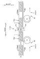
- FIG. 6A is a schematic plan view of the welding pattern PT51 for the temporary sealing process S51
- FIG. 6B is a schematic plan view of the welding pattern PT55 for the main sealing process S55.
- FIG. 6 is a schematic cross-sectional view for explaining that the trouble of breakage of the packaging sheet 12aa can be effectively prevented if the transport speed value V12aaad on the downstream side of the temporary device 51 is made smaller than the transport speed value V12aau on the upstream side.
- FIG. 8A is a schematic side view of the device 110 for folding the diaper 1 provided in the upstream portion of the packaging line, and FIG. 8B is a view taken along the line BB in FIG. 8A.
- a method of manufacturing a linked product of individually packaged products in which a plurality of individually packaged products in which absorbent articles are individually accommodated are arranged in an alignment direction In a state where a plurality of absorbent articles arranged in the alignment direction are accommodated inside a continuous sheet for packaging that is conveyed with the alignment direction as the conveyance direction, the absorbent article and the continuous sheet are combined together. Transporting in the transport direction; Of the cylindrical continuous sheet transported in the transport direction, a sealing target portion between the absorbent articles adjacent in the transport direction is a first pressing member in a crossing direction intersecting the transport direction.
- the sealing target portion in the cylindrical continuous sheet in which the absorbent article is accommodated inside is described above with the first pressing member. Are pressed in the crossing direction, and at least a part of the portion to be sealed is closed. Then, after that, the portion to be sealed whose at least part is closed is pressed and welded in the same crossing direction by the second pressing member, thereby forming a sealing portion in the portion. Therefore, before pressing with the second pressing member, the portion to be sealed is already in a substantially closed state, and thereby, in the transport direction that can occur in the portion to be sealed when pressed with the second pressing member.
- a method of manufacturing a linked product of individually packaged products relating to such an absorbent article In the closed state, at least a part of the sealing target portion is formed by pressing the sealing target portion with the first pressing member to form a welded portion on the sealing target portion. It is desirable to fix to a closed state.
- the manufacturing method of the connected product of the individually packaged product relating to such an absorbent article in the above-described closed state, by forming the welded portion in the sealing target portion, Fix at least some of them closed. Therefore, in forming the sealing portion to be performed thereafter, the sealing target portion fixed at least partially closed is welded by the second pressing member, so that the welding strength of the sealing portion is reduced. Can be effectively prevented.
- the total value of the area of the welded portion formed in the sealing target portion in the closed state is the area of the welded portion formed in the sealing target portion in forming the sealing portion. It is desirable to make it smaller than the total value.
- the total value of the area of the welded portion formed in the closed state is formed as the sealing portion.
- the area is smaller than the total area of the welded portions formed. Therefore, damage such as thermal damage due to the former welded portion that serves to fix at least a part of the sealing target portion in a closed state may adversely affect the strength of the latter welded portion that serves to form the sealed portion. Can be effectively prevented. And thereby, the welding strength of the sealing part formed generally based on the latter welding part can be raised.
- a method of manufacturing a linked product of individually packaged products relating to such an absorbent article In the closed state, the weld portion formed in the sealing target portion is formed with a first weld pattern, In forming the sealing portion, the weld portion formed in the portion to be sealed is formed with a second weld pattern, The size of the first welding pattern in the transport direction is preferably smaller than the size of the second welding pattern in the transport direction.
- the size of the first welding pattern in the transport direction is smaller than the size of the second welding pattern in the transport direction. Therefore, the welding part of the first welding pattern that serves to fix the sealing target part in a closed state protrudes from the welding part of the second welding pattern that serves to form the sealing part, so that the appearance of the sealing part is improved. Can be effectively prevented from becoming worse.
- a method of manufacturing a linked product of individually packaged products relating to such an absorbent article In the closed state, it is desirable that the welded portion is formed in a discontinuous pattern in the width direction of the continuous sheet.
- the welded portion formed in the sealing target portion in the closed state is formed in a discontinuous pattern in the width direction. ing. Therefore, an unwelded portion that is not welded exists between the welded portions adjacent in the width direction in the portion to be sealed. Therefore, even after the above-mentioned closed state, the air in the storage space of the absorbent article that the continuous sheet forms between the portions to be sealed is promptly passed through the unwelded portion. Can be removed. Therefore, it is not necessary to forcibly press the cylindrical continuous sheet or the like to forcibly release the air in the cylindrical continuous sheet before the closed state.
- a method of manufacturing a linked product of individually packaged products relating to such an absorbent article The closed state is performed by a pressing device arranged at a predetermined position in the transport direction,
- the conveying speed value (m / min) for receiving the continuous sheet from the pressing apparatus and conveying it downstream in the conveying direction is more than the conveying speed value (m / min) for feeding the continuous sheet to the pressing apparatus. Small is desirable.
- the continuous sheet breakage trouble that may occur when the latter conveyance speed value is equal to or greater than the former conveyance speed value is avoided. Can be prevented. Details are as follows. First, at a position upstream of the pressing device in the conveying direction, the continuous sheet is cylindrical, but when passing through the device, the cylindrical continuous sheet is crossed at the sealing target portion. Since it is pressed in the direction to be in a substantially closed state, the length of the continuous sheet in the conveyance direction is substantially reduced by that amount.
- the tension of the continuous sheet is the same as the shortening of the continuous sheet.
- the continuous sheet may be broken depending on the amount of increase.
- the conveyance speed value on the downstream side of the apparatus is made smaller than the conveyance speed value on the upstream side of the apparatus. Therefore, the increase in the tension of the sheet that can occur due to the shortening of the conveying direction of the continuous sheet can be alleviated, and thereby the trouble of breaking the sheet can be effectively prevented.
- a method of manufacturing a linked product of individually packaged products relating to such an absorbent article Fold the absorbent article in half so that the length of the absorbent article in the transport direction is shorter at the position upstream of the transport direction than the position where the transport is performed, In the transporting, the absorbent article and the continuous sheet are transported together in the transport direction in a state where the absorbent article in a folded state is accommodated inside the cylindrical continuous sheet. It is desirable that
- the absorbent article is folded in half and the length in the transport direction is shortened. Therefore, the length of the absorbent article in the conveyance direction of the individual packaged product can be shortened, thereby reducing the amount of the continuous sheet for packaging and reducing the manufacturing cost.
- the absorbent article is folded in half as described above, the dimensional difference in the intersecting direction increases in both the portion where the absorbent article is accommodated in the continuous sheet and the portion to be sealed. Then, the above-described tension that can be generated when the sealing target portion is pressed in the crossing direction becomes larger, and a decrease in the welding strength of the sealing portion can be promoted. Therefore, in the case of such a double fold, it is possible to more effectively enjoy the above-described operational effects exhibited by the present manufacturing method, that is, the operational effects of preventing a decrease in welding strength.
- the continuous sheet is preferably a single layer film made of polyethylene resin.
- the continuous sheet is a single layer film made of polyethylene resin
- the manufacturing cost of the connected product of the individually packaged product can be reduced.
- the polyethylene single-layer film has low strength due to its low cost. Therefore, if excessive tension acts in the conveying direction during welding, etc., there is a risk of breakage.
- the second pressing is performed to weld the portion to be sealed. It is possible to reduce the tension in the transport direction that may occur when the part to be sealed is pressed with a member. Therefore, when such a polyethylene single-layer film is used for a packaging sheet, the effects of the present production method can be enjoyed effectively.
- a method of manufacturing a linked product of individually packaged products relating to such an absorbent article At a position on the upstream side in the transport direction from the position where the transport is performed, Transporting a plurality of the absorbent articles arranged in the alignment direction with the alignment direction as the transport direction; Merging the absorbent article conveyed in the conveyance direction with the continuous sheet for packaging conveyed along the conveyance direction; Accommodating the absorbent article inward of the cylindrical continuous sheet by bending the continuous sheet that is merged and conveyed together with the absorbent article into a tubular shape by bending the continuous sheet in the width direction; It is desirable to do it.
- the manufacturing method of the connected product of the individually packaged product according to such an absorbent article in the state where the absorbent article aligned along the transport direction is accommodated inside the continuous sheet for cylindrical packaging, The continuous sheet and the absorbent article can be conveyed together in the conveyance direction.
- An apparatus for manufacturing a linked product of individually packaged products in which a plurality of individually packaged products each containing an absorbent article are arranged in the alignment direction, In a state where a plurality of absorbent articles arranged in the alignment direction are accommodated inside a continuous sheet for packaging that is conveyed with the alignment direction as the conveyance direction, the absorbent article and the continuous sheet are combined together.
- a device for conveying in the conveying direction Of the cylindrical continuous sheet transported in the transport direction, a sealing target portion between the absorbent articles adjacent in the transport direction is a first pressing member in a crossing direction intersecting the transport direction.
- a device that closes at least a part of the sealing target portion by pressing with, While transporting the continuous sheet in a state where at least a part of the sealing target portion is closed in the transport direction, the sealing target portion is pressed in the intersecting direction with a second pressing member and welded.
- it is an apparatus which forms the sealing part in the said sealing object part, It is a manufacturing apparatus of the connection goods of the individual packaging goods which concern on the absorbent article characterized by the above-mentioned.
- connection goods 11a of the individual package goods 11,11 ... which concern on the disposable diaper 1 as an example of an absorbent article.
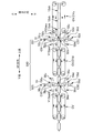
- FIG. 2A is a schematic top view of such a connected article 11a
- FIG. 2B is a view taken along the line BB in FIG. 2A
- FIG. 2C is a view taken along the line CC in FIG. 2A.
- 2A and 2C are partially enlarged views.
- FIG. 2A shows a so-called ten-line product in which ten individual packages 11, 11,...
- the connected product 11a in FIG. 2A is long and flexible with a length corresponding to, for example, 10 diapers 1, 1... Corresponding to the number of stations, and a length corresponding to, for example, 10 stations.
- Packaging sheet 12a On the packaging sheet 12a, ten diapers 1, 1,... Are placed in a line with the longitudinal direction of the packaging sheet 12a as the alignment direction in a state of being spaced apart from each other. Moreover, each edge part 12ae and 12ae of the width direction of the packaging sheet 12a are piled up on each diaper 1, and the packaging sheet 12a was made into the cylinder shape, and each these edge parts 12ae and 12ae heat By being welded with a seal, the shape of the packaging sheet 12a is fixed in a cylindrical shape.
- each of the portions 12ab between the diapers 1 and 1 in the cylindrical packaging sheet 12a (hereinafter also referred to as a sealing target portion 12ab) is subjected to welding treatment by heat sealing.
- Sealing portions 12as and 12as are formed. That is, as shown in the enlarged view of FIG. 2C, the surface portions 12abs1 and 12abs1 facing each other in the inner peripheral surface 12abs of the sealing target portion 12ab are welded in contact with each other. Stop portions 12as, 12as are formed.
- each diaper 1 is separately accommodated in the bag-shaped space divided by the said sealing part 12as, and, thereby, the connection goods 11a of the individual package goods 11,11 ... are substantially formed. As shown in the enlarged view of FIG.
- each sealing target portion 12ab has not only a pair of sealing portions 12as and 12as but also a perforation at a position between the sealing portions 12as and 12as.
- the perforated portion 12ac is also formed. And it can be separated for each individual packaged article 11 at the perforated part 12ac.
- a layer film is used.
- the diaper 1 packaged individually is a so-called pants-type diaper.
- the diaper 1 has an abdominal side portion disposed on the wearer's belly side, a crotch portion disposed on the wearer's crotch, and a back side portion disposed on the wearer's back side.
- the abdomen and the dorsal part can be separated by welding or the like at each end in the width direction while the abdomen and dorsal part are overlapped.
- the diaper 1 is a pants type having a waist opening and a pair of leg openings.
- the target of individual packaging is not limited to the pants-type diaper 1.
- an unfolded diaper that is, a type of diaper in which the front side and the rear side are connected using a fastening tape may be used, a sanitary napkin, or a diaper attached to the side of the skin. It may be a urine collecting pad.
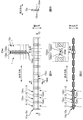
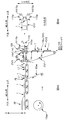
- FIG. 3 shows a schematic side view of the packaging line.
- the packaging line includes a wrapping step S30, a center sealing step S40, a sealing step S50, and a separating step S60 along the conveyance direction.
- the diaper 1 to be packaged and the continuous sheet 12aa of the packaging sheet 12a are sequentially arranged in the above steps S30, S40, S50, When passing through S60, corresponding processes are performed in the respective steps S30, S40,..., And finally the connected product 11a of the individually packaged products 11, 11.
- conveyance of the diaper 1 and packaging sheet 12aa between said process S30, S40, S50, S60 is performed with suitable conveyance apparatus CV.
- a suction belt conveyor having a suction holding function on a belt surface serving as a mounting surface a belt conveyor having a conveying path for diapers 1 between endless belts arranged in pairs above and below, or A conveyance roller etc. can be illustrated.
- Both the wrapping step S30 and the center sealing step S40 correspond to “conveying”, and a temporary sealing process described later in the sealing step S50.
- S51 and the main sealing process S55 correspond to “to close” and “to form a sealing portion”, respectively.
- the transport direction is also referred to as “MD direction”, and the direction orthogonal to the MD direction is also referred to as “CD direction”.
- the continuous direction of the packaging sheet 12aa is along the MD direction
- the width direction of the packaging sheet 12aa is along the CD direction.
- the longitudinal direction of the connection goods 11a of the individual packaged goods 11,11 ... manufactured is along MD direction
- the width direction of the connection goods 11a is along CD direction
- the connection goods The thickness direction of 11a is orthogonal to both the MD direction and the CD direction.
- each diaper 1 is wrapped in a cylindrical shape with the wrapping sheet 12aa.
- the packaging sheet 12aa is fed out from the packaging sheet roll 12aaar supported by an appropriate reel device 31, and is continuously conveyed in the MD direction.
- the packaging sheet 12aa joins each diaper 1 conveyed in a line along the MD direction separately from a production line (not shown) of the diaper 1 at a predetermined joining position Pj in the MD direction.
- the wrapping sheet 12aa joins from below with respect to the transport path of the diaper 1, whereby each diaper 1 is placed on the upper surface of the wrapping sheet 12aa, and thereafter the diaper 1 and the wrapping sheet 12aa. Are transported together.
- a wrapping guide plate 34 is provided in the step S30.
- the guide plate 34 bends the packaging sheet 12aa in the CD direction, and diapers each end 12aae, 12aae in the CD direction of the sheet 12aa. 1, the wrapping sheet 12aa is formed in a cylindrical shape and encloses the diaper 1.
- the end portions 12aae and 12aae of the overlapped packaging sheet 12aa are welded together, and the shape of the packaging sheet 12aa is fixed in a cylindrical shape.
- This welding process is performed by the heat seal device 40.
- the heat seal device 40 includes a heating unit 42 heated to a predetermined temperature.
- packaging sheet 12aa of the state which wrapped the diaper 1 in the cylinder shape passes the position of the heating part 42, the said heating part 42 is each end part 12aae and 12aae of the laminated
- the end portions 12aae and 12aae are heated and melted by contacting from above, and the end portions 12aae and 12aae are welded together. And thereby, the shape of packaging sheet 12aa is fixed to a cylinder shape.
- a pair of sealing portions 12as and 12as are formed in a sealing target portion 12ab which is a portion 12ab between the diapers 1 and 1 of the cylindrical packaging sheet 12aa.
- each diaper 1 is individually accommodated in the packaging sheet 12aa, that is, a continuous body 11aa of the individually packaged product 11 is generated.
- a perforated perforated portion 12ac is also formed at a position between the pair of sealing portions 12as and 12as in the sealing target portion 12ab. And thereby, the individually packaged goods 11 and 11 adjacent to MD direction are made into the state which can be separated easily. Details of the sealing step S50 will be described later.
- the downstream portion of the continuum 11aa of the packaged product 11 is separated by the target station number, thereby generating the connected product 11a of the packaged product 11 having the target station number.
- the separation process is performed by the separation device 60. That is, the separation device 60 is a cutting target specified corresponding to the target number of stations to be manufactured, such as ten, from among the plurality of perforated portions 12ac, 12ac. Only the perforated portion 12ac is cut, and the connected product 11a formed by connecting the individual packaged products 11, 11... And this is sent downstream as a final product.
- FIG. 4 is a schematic side view of the separating device 60.
- the separating device 60 has a pair of nip roll mechanisms 62 and 64 arranged side by side in the MD direction.
- Each nip roll mechanism 62, 64 has a pair of upper and lower nip rolls 62u, 62d, 64u, 64d that are driven and rotated about rotation axes C62, C64 along the CD direction.
- the upstream nip roll mechanism 62 positioned on the upstream side is a pair of upper and lower parts that are driven and rotated so as to send the continuum 11aa downstream in the MD direction while slightly sandwiching the continuum 11aa from both sides in the thickness direction on the outer peripheral surface.
- the downstream nip roll mechanism 64 having the nip rolls 62u and 62d and located downstream of the upstream nip roll mechanism 62 also includes the continuum 11aa slightly sandwiched between the outer peripheral surfaces from both sides in the thickness direction. Has a pair of upper and lower nip rolls 64u and 64d that are driven to rotate so as to be fed downstream in the MD direction.
- the nip rolls 62u, 62d, 64u, 64d of the upstream nip roll mechanism 62 and the downstream nip roll mechanism 64 are driven and rotated by a servo motor (not shown) as a drive source, and the peripheral speed values V62, V64. Is controlled so as to be substantially equal to the conveyance speed value V11aa of the continuous body 11aa.
- the peripheral speed value V62 of the upstream nip roll mechanism 62 is set to V1 as a steady speed value
- the peripheral speed value V64 of the downstream nip roll mechanism 64 is The steady speed value is set to V1 to 1.06V1.
- the controller of the separation device 60 detects that the perforated portion 12ac has reached between the upstream nip roll mechanism 62 and the downstream nip roll mechanism 64, the peripheral speed value V64 of the downstream nip roll mechanism 64 is detected. Only one of these is instantaneously increased from the steady speed value, and operates so as to immediately return to the steady speed value after the speed increase.
- the continuum 11aa is instantaneously pulled in the MD direction at a position between the upstream nip roll mechanism 62 and the downstream nip roll mechanism 64, and at this time, the perforated portion 12ac positioned therebetween is Selectively disconnected.
- the connected product 11a having the individual packaged products 11, 11,... For the target number of stations is separated from the continuous body 11aa. Note that the separated connected product 11a is transported to a shipping process or the like by the downstream transport device CV.
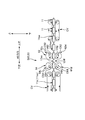
- FIG. 5 is an enlarged schematic side view showing the sealing step S50.
- the sealing process is performed twice. That is, first, the temporary sealing process S51 is performed, and then the main sealing process S55 is performed.
- the role of the temporary sealing process S51 is to press the sealing target portion 12ab with the first pressing members 52u and 52d in the thickness direction (vertical direction) which is an intersecting direction intersecting both the MD direction and the CD direction. Thus, at least a part of the sealing target portion 12ab is closed.
- the sealing target portion 12ab is already in a substantially closed state at the time before the main sealing process S55, and therefore in the thickness direction (corresponding to the crossing direction) in the main sealing process S55.
- the resistance force F due to the tension F along the MD direction that can occur in the sealing target portion 12ab that is, it is possible to effectively prevent the resistance force F hindering the closing from being increased, and as a result, a pair of seals formed in the sealing target portion 12ab in the sealing process S55. It is possible to effectively prevent a decrease in the welding strength of the portions 12as and 12as.
- “to make at least a part of the sealing target portion 12ab in a closed state” means “to make at least a part of the sealing target portion 12ab in the CD direction closed” More specifically, at least a part of the surface portions 12abs1 and 12abs1 facing each other in the inner circumferential surface 12abs of the sealing target portion 12ab are in contact with each other (see the enlarged view of FIG. 2C). ).
- the temporary sealing process S51 and the main sealing process S55 will be described.
- both the temporary sealing process S51 and the main sealing process S55 are performed by heat sealing devices 51 and 55 having substantially the same structure. And these two heat seal apparatuses 51 and 55 are arrange
- the heat sealing device 51 for the temporary sealing process S51 is referred to as a “temporary device 51”
- the device 55 is referred to as “this device 55”.
- the pair of sealing portions 12as1 and 12as1 formed on the sealing target portion 12ab by the temporary device 51 is referred to as “temporary sealing portion 12as1”, and is formed on the sealing target portion 12ab by the device 55.
- the pair of sealing portions 12as2 and 12as2 is referred to as “main sealing portion 12as2”.
- the main sealing portion 12as2 is substantially the same as the above-described sealing portion 12as, that is, a regular sealing portion 12as.
- Both the temporary device 51 and the present device 55 have a pair of upper and lower rolls 51u, 51d, 55u, 55d that are driven and rotated around rotation axes C51, C55 along the CD direction.
- the process parts 52u and 52d for forming temporary sealing part 12as1 and 12as1 are provided in the outer peripheral surface of each upper and lower roll 51u and 51d of the temporary apparatus 51, respectively. That is, in the heated processing portion 52u of the upper roll 51u, a plurality of protrusions t1, t1,... Are arranged in the welding pattern PT51 (FIG. 6A) for the temporary sealing portion 12as1, and the lower roll 51d is processed.
- the portion 52d is provided with a receiving surface for receiving the protrusions t1, t1,.
- processing portions 56u and 56d for forming the main sealing portions 12as2 and 12as2 are provided on the outer peripheral surfaces of the upper and lower rolls 55u and 55d of the apparatus 55, respectively. That is, in the heated processing portion 56u of the upper roll 55u, a plurality of protrusions t2, t2,... Are arranged in the welding pattern PT55 (FIG. 6B) for the main sealing portion 12as2, and the lower roll 55d is processed.
- the part 56d is provided with a receiving surface for receiving the protrusions t2, t2,.
- the rolls 51u, 51d, 55u, and 55d of the temporary device 51 and the main device 55 are driven and rotated in conjunction with the conveying operation of the packaging sheet 12aa by a servo motor (not shown) as a drive source. Therefore, when the sealing target portion 12ab of the packaging sheet 12aa passes through the gap between the upper and lower rolls 51u and 51d of the temporary device 51, the upper processing portion 52u and the lower processing portion 52d as the first pressing member are formed.
- a plurality of welded portions m1, m1,... As a pair of temporary sealing portions 12as1, 12as1 are welded to the sealing target portion 12ab. It is formed of PT51 (FIG. 6A).
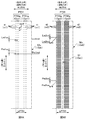
- FIG. 6A is a schematic plan view of the welding pattern PT51 for the temporary sealing process S51
- FIG. 6B is a schematic plan view of the welding pattern PT55 for the main sealing process S55.
- the former is also referred to as “temporary pattern PT51”, and the latter is also referred to as “main pattern PT55”.
- the temporary pattern PT51 (corresponding to the first welding pattern) has two rectangular patterns PT51a and PT51a arranged in the MD direction. And each rectangular pattern PT51a and PT51a are in charge of formation of welding part m1, m1, ... of each pair of each temporary sealing part 12as1, 12as1.
- this pattern PT55 (corresponding to the second welding pattern) also has two rectangular patterns PT55a and PT55a arranged in the MD direction (rotating direction), and each rectangular pattern PT55a and PT55a has a pair of each. In charge of forming the welded portions m2, m2,... Of the main sealing portions 12as2, 12as2.
- each of the two rectangular patterns PT51a and PT51a belonging to the temporary pattern PT51 and the two rectangular patterns PT55a and PT55a belonging to the present pattern PT55 are a plurality of welded portions m1.
- M1... (M2, m2...) Are arranged in a lattice pattern along the CD direction and the MD direction (rotation direction), respectively, and the bottom surfaces of the welded portions m1, m1.
- the shape of each is a square of the same shape and the same size.
- the rectangular patterns PT51a and PT51a of the temporary pattern PT51 are markedly more than the rectangular patterns PT55a and PT55a of the main pattern PT55. Small. In other words, the ratio of the total area of the welded portions m1, m1,... (M2, m2,%) Occupying the unit area of the sealing target portion 12ab is such that each rectangular pattern PT51a, PT51a of the temporary pattern PT51 has this pattern. It is much smaller than the rectangular patterns PT55a and PT55a of PT55. Therefore, the total value of the areas of the welded parts m1, m1,...
- the temporary pattern PT51 is much smaller than the total value of the areas of the welded parts m2, m2,. Thus, it is effective that damage such as thermal damage due to the temporary sealing portion 12as1 that serves to fix the sealing target portion 12ab in a substantially closed state adversely affects the welding strength on the main sealing portion 12as2. Can be prevented. As a result, it is possible to prevent a decrease in the welding strength of the main sealing portion 12as2 as a whole.
- the temporary pattern PT51 is set to the welded portions m2, m2,. It may be set to 1/2 to 1/2 of the total area, more preferably 1/8 to 1/10, and in this example, it is set to 1.88.
- the setting of the pressing forces P51 and P55 is realized by a known pressing force applying mechanism (not shown) such as a hydraulic cylinder or an air cylinder.
- the temporary device 51 and the present device 55 each have a frame-shaped housing member (not shown) on both sides in the CD direction, and each of the upper rolls 51u (55u) is provided on the inner peripheral side of each housing member.
- the end portion and each end portion of the lower roll 51d (55d) are accommodated side by side in the vertical direction, which is the thickness direction.
- a hydraulic cylinder or an air cylinder as a pressing force application mechanism is interposed between each housing member and each end portion of the lower roll 51d (55d), for example. 55d) is movably supported in the thickness direction.
- the processing unit 52 u (56 u) of the upper roll 51 u (55 u) is heated for both the temporary device 51 and the main device 55.
- 55u) is realized by incorporating a heating element (not shown) such as an electric heater.
- the heating temperature of the upper processing portion 52u (56u) is determined according to the material of the packaging sheet 12aa to be heated.
- the processing portion 52u, 56u is the same as the sheet 12aa is a single layer film of PE.
- the heating temperature is also set to an arbitrary value in the range of 120 ° C to 150 ° C.
- the heating temperature of the processing unit 53u of the temporary device 51 may be higher or lower than the heating temperature of the processing unit 56u of the present device 55. And if it is made like the latter, the damage of sealing object part 12ab in the above-mentioned temporary sealing process S51 can be reduced.
- the maximum values of the dimensions Lm1md and Lm2md in the MD direction of the welded portions m1 and m2 of the temporary pattern PT51 and the main pattern PT55 are, for example, in the range of 0.5 mm to 2.0 mm, respectively.
- the maximum values Lm1cd and Lm2cd of the dimension in the CD direction of the welded portions m1 and m2 are set to fall within a range of 0.5 mm to 2.0 mm, for example.
- the pitch Pm1md in the MD direction of the welded portion m1 in the rectangular pattern PT51a of the temporary pattern PT51 is set to fall within a range of, for example, 1.0 mm to 4.0 mm, and the pitch Pm1cd in the CD direction of the welded portion m1. Is set to fall within a range of 2.0 mm to 6.0 mm, for example.
- the pitch Pm2md in the MD direction of the welded portion m2 in the rectangular pattern PT55a of the present pattern PT55 is set to fall within a range of 1.0 mm to 3.0 mm, for example, and the pitch Pm2cd in the CD direction of the welded portion m2 Is set to fall within a range of, for example, 1.0 mm to 3.0 mm.
- the size LPT51 of the temporary pattern PT51 in the MD direction is made smaller than the size LPT55 of the main pattern PT55 in the MD direction. Therefore, the welded portions m1, m1,... Formed based on the temporary pattern PT51 so as to fix the sealing target portion 12ab in the substantially closed state are formed on the main pattern PT55 so as to form a pair of main sealed portions 12as2, 12as2. It is possible to effectively prevent the appearance of the pair of main sealing portions 12as2, 12as2 from deteriorating in the MD direction from the welded portions m2, m2,.
- the size LPT51 of the temporary pattern PT51 in the MD direction is set to fall within a range of 20 mm to 30 mm, for example, and the size LPT55 of the present pattern PT55 in the MD direction is set to be temporary. Taking care that the pattern PT51 is larger than the size LPT51, the pattern PT51 is set to fall within a range of 25 mm to 40 mm, for example.
- each of the rectangular patterns PT51a and PT51a related to the temporary pattern PT51 of FIG. 6A is a lattice pattern as described above, and thus is a discontinuous pattern in the CD direction. Therefore, the temporary sealing part 12as1 formed in the sealing target part 12ab has a plurality of welded parts m1, m1,... Formed discontinuously in the CD direction. That is, an unwelded portion mn1 that is not welded exists in the portion between the welded portions m1 and m1 adjacent in the CD direction in the sealing target portion 12ab.
- the air in the accommodation space of the diaper 1 in which the packaging sheet 12aa is partitioned between the sealing target portions 12ab and 12ab via the unwelded portion mn1. Can be quickly removed. That is, it is not necessary to forcibly press the cylindrical packaging sheet 12aa and remove air from the sheet 12aa before the temporary sealing process S51.
- the situation where the diaper 1 is pressed together with the portion 12ab and welded together can be effectively prevented.
- the packaging sheet 12aa is received from the temporary device 51 rather than the conveyance speed value V12aau (m / min) for sending the packaging sheet 12aa to the temporary device 51 (corresponding to the pressing device).
- the transport speed value V12aad (m / min) transported downstream in the MD direction is made smaller.
- the packaging sheet 12aa is cylindrical at a position upstream of the temporary device 51 in the MD direction, but when passing through the temporary device 51, the cylindrical packaging sheet 12aa is a portion to be sealed. Since the sheet 12ab is pressed in the thickness direction (vertical direction) to be substantially closed, the length of the packaging sheet 12aa in the MD direction is substantially shortened by the amount corresponding to the pressing amount LP.
- the conveyance speed value V12aaad of the packaging sheet 12aa on the downstream side of the temporary device 51 is set equal to or larger than the conveyance speed value V12aau on the upstream side of the apparatus 51, the shortening of the packaging sheet 12aa is performed. Only the tension of the packaging sheet 12aa increases, and the packaging sheet 12aa may break depending on the amount of increase.
- the transport speed value V12aaad on the downstream side of the temporary device 51 is set to be smaller than the transport speed value V12aau on the upstream side of the device 51, the above may occur due to shortening of the MD direction of the packaging sheet 12aa.
- the increase in the tension of the sheet 12aa can be mitigated, thereby effectively preventing the trouble of breakage of the sheet 12aa.
- the setting of the conveyance speed values V12aad and V12aau is such that the peripheral speed value VBd (m / min) of the endless belt Bd of the belt conveyor CVd located immediately downstream of the temporary device 51 is set immediately upstream of the temporary device 51. This can be done by making it smaller than the peripheral speed value VBu (m / min) of the endless belt Bu of the belt conveyor CVu located.
- an arbitrary value in the range of 0.7 to 0.9 can be exemplified as the ratio RV.
- the ratio RV is selected from the said range, in the packaging of the diaper 1 for children, the trouble of breakage of the packaging sheet 12aa can be surely prevented.
- FIG. 8B shows a schematic diagram of the apparatus 100 that performs folding in half. 8B is a view taken along arrow BB in FIG. 8A.
- the apparatus 100 has a transport path TR bent in the MD direction formed by a plurality of belt conveyors CV1, CV2, and CV3. That is, the transport path TR has an upstream transport path part TRu and a downstream transport path part TRd, and the downstream transport path part TRd has a predetermined inclination angle (on the downstream side of the upstream transport path part TRu). In the example of FIG. 8A, they are connected by 90 °).
- the apparatus 100 includes an impeller device 110 at a connection position Pb between the upstream transport path portion TRu and the downstream transport path portion TRd.
- It may be fixed to the state, or, like a needle punch, by pressing the sealing target portion 12ab with a plurality of needle-like members and penetrating through the portion 12ab, an engaging portion that engages mechanically is provided. It may be formed and the part 12ab may be fixed in a closed state. Furthermore, it is only necessary to be in a closed state, that is, it is not necessarily fixed in the closed state.
- the sealing target portion 12ab is pressed in the thickness direction orthogonal to both the MD direction and the CD direction to form the temporary sealing portion 12as1 and the main sealing portion 12as2.
- the pressing direction is not limited to this. That is, if it is a direction crossing the MD direction, the “pressing direction” can be used.
- the temporary sealing portion 12as1 and the main sealing portion 12as2 may be formed by pressing the sealing target portion 12ab in the CD direction.
- the temporary sealing portion 12as1 and the main sealing portion 12as2 may be formed by pressing in any direction between the thickness direction and the CD direction.
- the upper processed portion 52u as the first pressing member and the upper processed portion 56u as the second pressing member rotate around the rotation axes C51 and C55, respectively.
- the portion 12ab is pressed
- the present invention is not limited to this.
- the first pressing member or the second pressing member performs a so-called box motion
- the temporary sealing portion 12as1 and the main sealing portion 12as2 are pressed and formed on the sealing target portion 12ab continuously conveyed in the MD direction.
- the “box motion” means that the first or second pressing member moves downstream in the MD direction in conjunction with the conveyance of the sealing target portion 12ab while the pressing member moves the sealing target portion 12ab in the thickness direction.
- the operation of pressing the member to the sealing target portion 12ab while the pressing member reverses the moving operation in the MD direction to the upstream and returns to the start position of the moving operation to the downstream, Is repeatedly performed.
Landscapes
- Health & Medical Sciences (AREA)
- Engineering & Computer Science (AREA)
- Epidemiology (AREA)
- Life Sciences & Earth Sciences (AREA)
- Heart & Thoracic Surgery (AREA)
- Vascular Medicine (AREA)
- Biomedical Technology (AREA)
- Animal Behavior & Ethology (AREA)
- General Health & Medical Sciences (AREA)
- Public Health (AREA)
- Veterinary Medicine (AREA)
- Mechanical Engineering (AREA)
- Absorbent Articles And Supports Therefor (AREA)
- Containers And Plastic Fillers For Packaging (AREA)
- Package Closures (AREA)
Abstract
吸収性物品が個別収容されてなる複数の個別包装品が整列方向に並んでなる個別包装品の連結品の製造方法である。前記整列方向に並ぶ複数の吸収性物品を、前記整列方向を搬送方向として搬送される筒状の包装用の連続シートの内方に収容した状態で、前記吸収性物品と前記連続シートとを一緒に前記搬送方向に搬送することと、前記搬送方向に搬送される前記筒状の前記連続シートのうちで前記搬送方向に隣り合う前記吸収性物品同士の間の封止対象部分を、前記搬送方向と交差する交差方向に第1押圧部材で押圧することにより、前記封止対象部分のうちの少なくとも一部を閉じた状態にすることと、前記封止対象部分のうちの少なくとも一部が閉じた状態にされた前記連続シートを前記搬送方向に搬送しながら、前記封止対象部分を第2押圧部材で前記交差方向に押圧して溶着することにより、前記封止対象部分に封止部を形成することと、を有する。
Description
本発明は、使い捨ておむつ等の吸収性物品に係る個別包装品の連結品の製造方法、及び製造装置に関する。
従来、小売店では、使い捨ておむつ等の吸収性物品が、10個等の所定数を1パックとして袋詰めされて販売されている。しかし、国や地域によっては、切り売りに似た販売形態がとられることがある。すなわち、店頭には、おむつを個別包装してなる個別包装品が、例えば10個だけ一列に連結してなる連結品の形態で陳列されている。そして、購入時には、かかる10連の連結品において個別包装品同士の間の各部分に予め形成されたミシン目状の目打ち部で、連結品から個別包装品を必要数だけ切り離して購入している。
特許文献1には、このような個別包装品の連結品をピロー包装法で製造する装置が開示されている。すなわち、この製造装置には、搬送方向に並んだ状態で同方向に沿って複数のおむつが送り込まれる。そして、先ず、各おむつが包み込み装置を通過する際には、各おむつに包装用の連続シートが合流するとともに、同シートが幅方向に曲げられて同シートが筒状にされ、これにより、各おむつは同シートに包み込まれて収容される。次に、この筒状の連続シートに包み込まれて収容された各おむつがセンターシール装置を通過する際には、各おむつの上方で互いに重なり合う連続シートの幅方向の各端部に溶着処理がなされ、これにより、連続シートの形状は筒形に固定される。そして、その次のエンドシール装置を通過する際には、筒状の連続シートにおけるおむつ同士の間の各部分を、エンドシーラーで、搬送方向及び幅方向の両者と交差する厚さ方向に押圧して閉じながら溶着し、これにより当該部分に封止部が形成される。そして、当該封止部の形成に伴って連続シートにおける封止部同士の間の各部分はそれぞれ袋部となって、各おむつは対応する袋部に個別収容された状態になる。そして、最後のカッター装置を通過する際には、上記封止部が形成された上記の各部分に対して、3つに2つの割合で目打ち部が形成され、残りの3つに1つの割合で切断され、これにより、3つの個別包装品が目打ち部を介して連結されてなる所謂3連品の個別包装品の連結品が製造される。
しかしながら、図1の概略断面図に示すように、一般におむつ1は、厚さ方向にある程度の大きさを有している。そのため、上記の封止部を形成すべく、筒状の連続シート12aaのうちのおむつ1,1同士の間の部分12abをエンドシーラー151a,151bで厚さ方向に押圧して閉じながら溶着する際に、同部分12abを厚さ方向に押し込むので、当該部分12abには搬送方向に沿った張力Fが生じる。そして、かかる張力Fは、上記部分12abが閉じるのを阻害する抵抗力Fとなる。よって、当該張力Fが大きいと、同部分12abに形成される封止部の溶着強度の低下を招き得る。
また、上記のエンドシーラー151a,151bの押し込みの際には、下流側に連続する個別包装品11,11…を図らずも上流側に引き込むことから、上記の張力Fは、下流側に連続する個別包装品11,11…の数が多いほど大きくなると考えられる。そのため、かかる溶着強度の低下の問題は、個別包装品11,11…の連結品11aの製造において特に顕在化し易いものと考えられる。
本発明は、上記のような従来の問題に鑑みてなされたものであって、その目的は、筒状にされた包装用の連続シートにおける吸収性物品同士の間の部分を溶着することで個別包装品の封止部を形成する際に、当該封止部の溶着強度の低下を防ぐことにある。
上記目的を達成するための主たる発明は、
吸収性物品が個別収容されてなる複数の個別包装品が整列方向に並んでなる個別包装品の連結品の製造方法であって、
前記整列方向に並ぶ複数の吸収性物品を、前記整列方向を搬送方向として搬送される筒状の包装用の連続シートの内方に収容した状態で、前記吸収性物品と前記連続シートとを一緒に前記搬送方向に搬送することと、
前記搬送方向に搬送される前記筒状の前記連続シートのうちで前記搬送方向に隣り合う前記吸収性物品同士の間の封止対象部分を、前記搬送方向と交差する交差方向に第1押圧部材で押圧することにより、前記封止対象部分のうちの少なくとも一部を閉じた状態にすることと、
前記封止対象部分のうちの少なくとも一部が閉じた状態にされた前記連続シートを前記搬送方向に搬送しながら、前記封止対象部分を第2押圧部材で前記交差方向に押圧して溶着することにより、前記封止対象部分に封止部を形成することと、を有することを特徴とする吸収性物品に係る個別包装品の連結品の製造方法である。
また、
吸収性物品が個別収容されてなる複数の個別包装品が整列方向に並んでなる個別包装品の連結品の製造装置であって、
前記整列方向に並ぶ複数の吸収性物品を、前記整列方向を搬送方向として搬送される筒状の包装用の連続シートの内方に収容した状態で、前記吸収性物品と前記連続シートとを一緒に前記搬送方向に搬送する装置と、
前記搬送方向に搬送される前記筒状の前記連続シートのうちで前記搬送方向に隣り合う前記吸収性物品同士の間の封止対象部分を、前記搬送方向と交差する交差方向に第1押圧部材で押圧することにより、前記封止対象部分のうちの少なくとも一部を閉じた状態にする装置と、
前記封止対象部分のうちの少なくとも一部が閉じた状態にされた前記連続シートを前記搬送方向に搬送しながら、前記封止対象部分を第2押圧部材で前記交差方向に押圧して溶着することにより、前記封止対象部分に封止部を形成する装置と、を有することを特徴とする吸収性物品に係る個別包装品の連結品の製造装置である。
本発明の他の特徴については、本明細書及び添付図面の記載により明らかにする。
本発明によれば、筒状にされた包装用の連続シートにおける吸収性物品同士の間の部分を溶着することで個別包装品の封止部を形成する際に、当該封止部の溶着強度の低下を防ぐことができる。
本明細書及び添付図面の記載により、少なくとも以下の事項が明らかとなる。
吸収性物品が個別収容されてなる複数の個別包装品が整列方向に並んでなる個別包装品の連結品の製造方法であって、
前記整列方向に並ぶ複数の吸収性物品を、前記整列方向を搬送方向として搬送される筒状の包装用の連続シートの内方に収容した状態で、前記吸収性物品と前記連続シートとを一緒に前記搬送方向に搬送することと、
前記搬送方向に搬送される前記筒状の前記連続シートのうちで前記搬送方向に隣り合う前記吸収性物品同士の間の封止対象部分を、前記搬送方向と交差する交差方向に第1押圧部材で押圧することにより、前記封止対象部分のうちの少なくとも一部を閉じた状態にすることと、
前記封止対象部分のうちの少なくとも一部が閉じた状態にされた前記連続シートを前記搬送方向に搬送しながら、前記封止対象部分を第2押圧部材で前記交差方向に押圧して溶着することにより、前記封止対象部分に封止部を形成することと、を有することを特徴とする吸収性物品に係る個別包装品の連結品の製造方法である。
このような吸収性物品に係る個別包装品の連結品の製造方法によれば、先ず、内方に吸収性物品が収容された筒状の連続シートにおける封止対象部分を第1押圧部材で上記の交差方向に押圧して、封止対象部分のうちの少なくとも一部を閉じた状態にする。そして、しかる後に、当該少なくとも一部が閉じた状態にされた封止対象部分を第2押圧部材で同じく交差方向に押圧して溶着し、これにより、当該部分に封止部を形成する。よって、当該第2押圧部材で押圧する前に、既に封止対象部分は概ね閉じた状態にあって、これにより、同第2押圧部材で押圧する際に封止対象部分に生じ得る搬送方向の張力起因の抵抗力、すなわち封止対象部分が閉じるのを阻害する抵抗力を軽減することができる。そして、これにより、第2押圧部材で封止対象部分を確実に閉じた状態にしながら溶着を安定して行うことができて、その結果、封止部の溶着強度の低下を防ぐことができる。
かかる吸収性物品に係る個別包装品の連結品の製造方法であって、
前記閉じた状態にすることにおいては、前記第1押圧部材で前記封止対象部分を押圧して前記封止対象部分に溶着部を形成することによって、前記封止対象部分のうちの少なくとも一部を閉じた状態に固定するのが望ましい。
前記閉じた状態にすることにおいては、前記第1押圧部材で前記封止対象部分を押圧して前記封止対象部分に溶着部を形成することによって、前記封止対象部分のうちの少なくとも一部を閉じた状態に固定するのが望ましい。
このような吸収性物品に係る個別包装品の連結品の製造方法によれば、上記の閉じた状態にすることにおいては、封止対象部分に溶着部を形成することによって、封止対象部分のうちの少なくとも一部を閉じた状態に固定する。よって、その後になされる封止部を形成することにおいては、少なくとも一部が閉じた状態に固定された封止対象部分を第2押圧部材で溶着するため、封止部の溶着強度の低下を有効に防ぐことができる。
かかる吸収性物品に係る個別包装品の連結品の製造方法であって、
前記閉じた状態にすることにおいて前記封止対象部分に形成される前記溶着部の面積の合計値は、前記封止部を形成することにおいて前記封止対象部分に形成される溶着部の面積の合計値よりも小さくされているのが望ましい。
前記閉じた状態にすることにおいて前記封止対象部分に形成される前記溶着部の面積の合計値は、前記封止部を形成することにおいて前記封止対象部分に形成される溶着部の面積の合計値よりも小さくされているのが望ましい。
このような吸収性物品に係る個別包装品の連結品の製造方法によれば、上記の閉じた状態にすることにおいて形成される溶着部の面積の合計値を、上記の封止部を形成することにおいて形成される溶着部の面積の合計値よりも小さくしている。よって、封止対象部分のうちの少なくとも一部を閉じた状態に固定する役割の前者の溶着部による熱損傷等のダメージが、封止部を形成する役割の後者の溶着部に強度上の悪影響を及ぼすことを有効に防ぐことができる。そして、これにより、総じて後者の溶着部に基づき形成される封止部の溶着強度を高めることができる。
かかる吸収性物品に係る個別包装品の連結品の製造方法であって、
前記閉じた状態にすることにおいて前記封止対象部分に形成される前記溶着部は、第1溶着パターンで形成され、
前記封止部を形成することにおいて前記封止対象部分に形成される溶着部は、第2溶着パターンで形成され、
前記第1溶着パターンの前記搬送方向の大きさは、前記第2溶着パターンの前記搬送方向の大きさよりも小さいのが望ましい。
前記閉じた状態にすることにおいて前記封止対象部分に形成される前記溶着部は、第1溶着パターンで形成され、
前記封止部を形成することにおいて前記封止対象部分に形成される溶着部は、第2溶着パターンで形成され、
前記第1溶着パターンの前記搬送方向の大きさは、前記第2溶着パターンの前記搬送方向の大きさよりも小さいのが望ましい。
このような吸収性物品に係る個別包装品の連結品の製造方法によれば、第1溶着パターンの搬送方向の大きさは、第2溶着パターンの搬送方向の大きさよりも小さくされている。よって、封止対象部分を閉じた状態に固定する役割の第1溶着パターンの溶着部が、封止部を形成する役割の第2溶着パターンの溶着部からはみ出してしまって、封止部の見栄えが悪くなることを有効に防ぐことができる。
かかる吸収性物品に係る個別包装品の連結品の製造方法であって、
前記閉じた状態にすることにおいては、前記溶着部を、前記連続シートの幅方向に非連続なパターンで形成するのが望ましい。
前記閉じた状態にすることにおいては、前記溶着部を、前記連続シートの幅方向に非連続なパターンで形成するのが望ましい。
このような吸収性物品に係る個別包装品の連結品の製造方法によれば、閉じた状態にすることにおいて封止対象部分に形成される溶着部は、幅方向に非連続なパターンで形成されている。よって、当該封止対象部分において幅方向に隣り合う溶着部同士の間には、溶着されていない未溶着部分が存在している。そのため、上記の閉じた状態にすることの後の時点でも、当該未溶着部分を介して、連続シートが封止対象部分同士の間に区画形成する吸収性物品の収容空間内のエアーを速やかに抜くことができる。そのため、上記の閉じた状態にすることよりも前の時点で、強制的に筒状の連続シートを押圧等して当該筒状の連続シート内のエアーを抜かなくて済む。そして、これにより、当該強制的に押圧する際に起こり得る上記収容空間から封止対象部分への吸収性物品のはみ出しを有効に防ぐことができて、その結果、封止部の形成時に封止対象部分と一緒に吸収性物品が押圧されて溶着されてしまう事態たる所謂「製品噛み不良」を有効に防ぐことができる。
かかる吸収性物品に係る個別包装品の連結品の製造方法であって、
前記閉じた状態にすることは、前記搬送方向の所定位置に配された押圧装置によって行われ、
前記押圧装置へと前記連続シートを送り込む搬送速度値(m/分)よりも、前記押圧装置から前記連続シートを受け取って前記搬送方向の下流へ搬送する搬送速度値(m/分)の方が小さいのが望ましい。
前記閉じた状態にすることは、前記搬送方向の所定位置に配された押圧装置によって行われ、
前記押圧装置へと前記連続シートを送り込む搬送速度値(m/分)よりも、前記押圧装置から前記連続シートを受け取って前記搬送方向の下流へ搬送する搬送速度値(m/分)の方が小さいのが望ましい。
このような吸収性物品に係る個別包装品の連結品の製造方法によれば、後者の搬送速度値が前者の搬送速度値と同値或いはそれよりも大きい場合に起こり得る上記連続シートの破断トラブルを防ぐことができる。詳しくは次の通りである。
先ず、上記押圧装置よりも搬送方向の上流側の位置では、連続シートは筒状となっているが、同装置を通過する際には、筒状の連続シートは、封止対象部分において上記交差方向に押圧されて略閉じた状態にされるので、その分だけ実質的に連続シートの搬送方向の長さが短縮されている。そのため、この押圧装置の下流側における連続シートの搬送速度値を、仮に同装置の上流側の搬送速度値と同値或いはそれよりも大きくした場合には、連続シートの上記短縮分だけ連続シートの張力が増大し、その増大量によっては、連続シートが破断してしまう恐れがある。この点につき、上記の本製造方法によれば、同装置の下流側での搬送速度値を同装置の上流側での搬送速度値よりも小さくしている。よって、連続シートの搬送方向の短縮起因で起こり得る同シートの張力の増大を緩和することができて、これにより、同シートの破断トラブルを有効に防ぐことができる。
先ず、上記押圧装置よりも搬送方向の上流側の位置では、連続シートは筒状となっているが、同装置を通過する際には、筒状の連続シートは、封止対象部分において上記交差方向に押圧されて略閉じた状態にされるので、その分だけ実質的に連続シートの搬送方向の長さが短縮されている。そのため、この押圧装置の下流側における連続シートの搬送速度値を、仮に同装置の上流側の搬送速度値と同値或いはそれよりも大きくした場合には、連続シートの上記短縮分だけ連続シートの張力が増大し、その増大量によっては、連続シートが破断してしまう恐れがある。この点につき、上記の本製造方法によれば、同装置の下流側での搬送速度値を同装置の上流側での搬送速度値よりも小さくしている。よって、連続シートの搬送方向の短縮起因で起こり得る同シートの張力の増大を緩和することができて、これにより、同シートの破断トラブルを有効に防ぐことができる。
かかる吸収性物品に係る個別包装品の連結品の製造方法であって、
前記搬送することを行う位置よりも前記搬送方向の上流側の位置では、前記吸収性物品の前記搬送方向の長さが短くなるように前記吸収性物品を二つ折りし、
前記搬送することにおいては、二つ折り状態の前記吸収性物品が前記筒状の前記連続シートの内方に収容された状態で、前記吸収性物品と前記連続シートとが一緒に前記搬送方向に搬送されているのが望ましい。
前記搬送することを行う位置よりも前記搬送方向の上流側の位置では、前記吸収性物品の前記搬送方向の長さが短くなるように前記吸収性物品を二つ折りし、
前記搬送することにおいては、二つ折り状態の前記吸収性物品が前記筒状の前記連続シートの内方に収容された状態で、前記吸収性物品と前記連続シートとが一緒に前記搬送方向に搬送されているのが望ましい。
このような吸収性物品に係る個別包装品の連結品の製造方法によれば、吸収性物品は二つ折りされて搬送方向の長さが短くなっている。よって、吸収性物品の個別包装品の搬送方向の長さを短縮することができて、これにより、包装用の連続シートの使用量を減らせて、製造コストの削減を図れる。
また、上述のように吸収性物品を二つ折りにした場合には、連続シートにおいて吸収性物品が収容された部分と封止対象部分との両者で、上記交差方向の寸法差が拡大する。すると、封止対象部分を交差方向に押圧する際に生じ得る既述の張力がより大きくなって、封止部の溶着強度の低下を助長し得る。そのため、かかる二つ折りの場合に、本製造方法が奏する前述の作用効果、すなわち、溶着強度の低下の防止の作用効果をより効果的に享受することができる。
また、上述のように吸収性物品を二つ折りにした場合には、連続シートにおいて吸収性物品が収容された部分と封止対象部分との両者で、上記交差方向の寸法差が拡大する。すると、封止対象部分を交差方向に押圧する際に生じ得る既述の張力がより大きくなって、封止部の溶着強度の低下を助長し得る。そのため、かかる二つ折りの場合に、本製造方法が奏する前述の作用効果、すなわち、溶着強度の低下の防止の作用効果をより効果的に享受することができる。
かかる吸収性物品に係る個別包装品の連結品の製造方法であって、
前記連続シートはポリエチレン樹脂製の単層フィルムであるのが望ましい。
前記連続シートはポリエチレン樹脂製の単層フィルムであるのが望ましい。
このような吸収性物品に係る個別包装品の連結品の製造方法によれば、連続シートはポリエチレン樹脂製の単層フィルムなので、個別包装品の連結品の製造コストを低廉にすることができる。
また、かかるポリエチレン製の単層フィルムは低廉な分、強度が低い。そのため、溶着時等に搬送方向に過大な張力が作用すると、破断の恐れがあるが、この点につき、本製造方法によれば、既述のように封止対象部分を溶着すべく第2押圧部材で封止対象部分を押圧する際に生じ得る搬送方向の張力を軽減可能である。よって、かかるポリエチレン製の単層フィルムを包装用シートに用いた場合には、本製造方法の作用効果を効果的に享受することができる。
また、かかるポリエチレン製の単層フィルムは低廉な分、強度が低い。そのため、溶着時等に搬送方向に過大な張力が作用すると、破断の恐れがあるが、この点につき、本製造方法によれば、既述のように封止対象部分を溶着すべく第2押圧部材で封止対象部分を押圧する際に生じ得る搬送方向の張力を軽減可能である。よって、かかるポリエチレン製の単層フィルムを包装用シートに用いた場合には、本製造方法の作用効果を効果的に享受することができる。
かかる吸収性物品に係る個別包装品の連結品の製造方法であって、
前記搬送することを行う位置よりも前記搬送方向の上流側の位置では、
前記整列方向に並ぶ複数の前記吸収性物品を、前記整列方向を前記搬送方向として搬送することと、
前記搬送方向に搬送される前記吸収性物品に、前記搬送方向に沿って搬送される前記包装用の連続シートを合流させることと、
合流されて前記吸収性物品と一緒に搬送される前記連続シートを幅方向に曲げて筒状にすることにより、筒状の前記連続シートの内方に前記吸収性物品を収容することと、を行うのが望ましい。
前記搬送することを行う位置よりも前記搬送方向の上流側の位置では、
前記整列方向に並ぶ複数の前記吸収性物品を、前記整列方向を前記搬送方向として搬送することと、
前記搬送方向に搬送される前記吸収性物品に、前記搬送方向に沿って搬送される前記包装用の連続シートを合流させることと、
合流されて前記吸収性物品と一緒に搬送される前記連続シートを幅方向に曲げて筒状にすることにより、筒状の前記連続シートの内方に前記吸収性物品を収容することと、を行うのが望ましい。
このような吸収性物品に係る個別包装品の連結品の製造方法によれば、筒状の包装用の連続シートの内方に、搬送方向に沿って整列した吸収性物品を収容した状態で、当該連続シートと吸収性物品とを一緒に搬送方向に搬送することが可能となる。
また、
吸収性物品が個別収容されてなる複数の個別包装品が整列方向に並んでなる個別包装品の連結品の製造装置であって、
前記整列方向に並ぶ複数の吸収性物品を、前記整列方向を搬送方向として搬送される筒状の包装用の連続シートの内方に収容した状態で、前記吸収性物品と前記連続シートとを一緒に前記搬送方向に搬送する装置と、
前記搬送方向に搬送される前記筒状の前記連続シートのうちで前記搬送方向に隣り合う前記吸収性物品同士の間の封止対象部分を、前記搬送方向と交差する交差方向に第1押圧部材で押圧することにより、前記封止対象部分のうちの少なくとも一部を閉じた状態にする装置と、
前記封止対象部分のうちの少なくとも一部が閉じた状態にされた前記連続シートを前記搬送方向に搬送しながら、前記封止対象部分を第2押圧部材で前記交差方向に押圧して溶着することにより、前記封止対象部分に封止部を形成する装置と、を有することを特徴とする吸収性物品に係る個別包装品の連結品の製造装置である。
このような吸収性物品に係る個別包装品の連結品の製造装置によれば、前述の製造方法と同様の作用効果を奏することができる。
===本実施形態===
本実施形態の製造方法及び製造装置は、吸収性物品の一例としての使い捨ておむつ1に係る個別包装品11,11…の連結品11aを製造する。図2Aは、かかる連結品11aの概略上面図であり、図2Bは、図2A中のB-B矢視図であり、図2Cは、図2A中のC-C矢視図である。なお、図2A及び図2C中には、それぞれ一部拡大図を併記している。
本実施形態の製造方法及び製造装置は、吸収性物品の一例としての使い捨ておむつ1に係る個別包装品11,11…の連結品11aを製造する。図2Aは、かかる連結品11aの概略上面図であり、図2Bは、図2A中のB-B矢視図であり、図2Cは、図2A中のC-C矢視図である。なお、図2A及び図2C中には、それぞれ一部拡大図を併記している。
図2Aに示すように、個別包装品11,11…の連結品11aは、おむつ1を包装シート12で個別に包んでなる複数の個別包装品11,11…が一列の整列状態で連結されたものである。そして、図2Aには、複数の一例として10個の個別包装品11,11…が一列に連続してなる所謂10連品が示されている。
詳しくは、図2Aの連結品11aは、連数に対応する数たる例えば10個のおむつ1,1…と、連数に対応する長さたる例えば10連分の長さ寸法の長尺且つ柔軟な包装シート12aと、を有する。そして、この包装シート12a上には、10個のおむつ1,1…が互いの間に間隔をあけた状態で包装シート12aの長手方向を整列方向として一列に載置されている。また、包装シート12aの幅方向の各端部12ae,12ae同士は、各おむつ1の上方で重ね合わせられて包装シート12aが筒状にされた状態で、これら各端部12ae,12ae同士がヒートシールで溶着されることにより、包装シート12aの形状は筒状に固定されている。更に、筒状の包装シート12aにおけるおむつ1,1同士の間の各部分12ab(以下、封止対象部分12abとも言う)にも、ヒートシールで溶着処理が施されていて、これにより、一対の封止部12as,12asが形成されている。すなわち、図2Cの拡大図に示すように、封止対象部分12abの内周面12absのうちで互いに対向する面部分12abs1,12abs1同士が接触した状態で溶着されていて、これにより、一対の封止部12as,12asが形成されている。そして、当該封止部12asによって区画される袋状の空間に各おむつ1は個別収容されており、これにより、個別包装品11,11…の連結品11aがほぼ形成されている。なお、図2Aの拡大図に示すように、各封止対象部分12abには、当該一対の封止部12as,12asだけでなく、これら封止部12as,12as同士の間の位置にミシン目状の目打ち部12acも形成されている。そして、当該目打ち部12acにて、個別包装品11毎に切り離し可能となっている。
かかる包装シート12aの材料には、ポリエチレン(PE)やポリプロピレン(PP)等の樹脂繊維を主材とする不織布、或いはPEやPP等の樹脂フィルムが使用され、この例では、安価なPEの単層フィルムが使用されている。
また、この例では、個別包装されるおむつ1は、所謂パンツ型おむつである。詳しくは、同おむつ1は、着用者の腹側に配される腹側部と、着用者の股間に配される股下部と、着用者の背側に配される背側部と、を有する。そして、股下部で二つ折りされることにより、腹側部と背側部とが重ね合わせられた状態で、腹側部と背側部とを幅方向の各端部で溶着等により分離不能に連結しており、これにより、当該おむつ1は、胴回り開口部と一対の脚回り開口部とを有したパンツ型となっている。但し、個別包装の対象は、何等パンツ型のおむつ1に限らない。例えば、展開型おむつ、すなわちファスニングテープを用いて前側部と後側部とを連結して装着するタイプのおむつでも良いし、生理用ナプキンでも良いし、更には、おむつの肌側面に取り付けて使用される尿取りパッドでも良い。
<<<包装ラインについて>>>
このような個別包装品の連結品11aは、包装ラインで製造される。図3に包装ラインの概略側面図を示す。包装ラインは、搬送方向に沿って、包み込み工程S30と、センターシール工程S40と、封止工程S50と、切り離し工程S60と、を有する。そして、包装対象のおむつ1及び包装シート12aの連続シート12aa(「包装用の連続シート」に相当し、以下、単に包装シート12aaと言う)が、順次、上記の各工程S30,S40,S50,S60を通過する際に、各工程S30,S40…においてそれぞれ対応する処理がなされて、最終的に個別包装品11,11…の連結品11aが製造される。
このような個別包装品の連結品11aは、包装ラインで製造される。図3に包装ラインの概略側面図を示す。包装ラインは、搬送方向に沿って、包み込み工程S30と、センターシール工程S40と、封止工程S50と、切り離し工程S60と、を有する。そして、包装対象のおむつ1及び包装シート12aの連続シート12aa(「包装用の連続シート」に相当し、以下、単に包装シート12aaと言う)が、順次、上記の各工程S30,S40,S50,S60を通過する際に、各工程S30,S40…においてそれぞれ対応する処理がなされて、最終的に個別包装品11,11…の連結品11aが製造される。
なお、上記工程S30,S40,S50,S60同士の間のおむつ1及び包装シート12aaの搬送は、適宜な搬送装置CVで行われる。搬送装置CVとしては、例えば、載置面たるベルト面に吸着保持機能を有したサクションベルトコンベアや、上下に対で配された無端ベルト同士の間をおむつ1の搬送路とするベルトコンベア、あるいは搬送ローラー等を例示できる。
また、ここで請求項の用語との対応関係について述べると、上記の包み込み工程S30及びセンターシール工程S40の両者が、「搬送すること」に相当し、封止工程S50における後述の仮封止処理S51及び本封止処理S55が、それぞれ「閉じた状態にすること」及び「封止部を形成すること」に相当している。
以下、各工程S30,S40,S50,S60について説明するが、以下の説明では、搬送方向のことを「MD方向」とも言い、MD方向と直交する方向のことを「CD方向」とも言う。なお、包装シート12aaの連続方向は、MD方向に沿っており、また、同包装シート12aaの幅方向は、CD方向に沿っている。また、製造される個別包装品11,11…の連結品11aの長手方向は、MD方向に沿っているとともに、同連結品11aの幅方向は、CD方向に沿っており、更に、同連結品11aの厚さ方向は、MD方向及びCD方向の両方向と直交している。
最初の包み込み工程S30では、各おむつ1を包装シート12aaで筒状に包み込む。詳しくは、適宜なリール装置31に支持された包装シートロール12aarから、包装シート12aaが繰り出されて、MD方向に連続して搬送される。そして、同包装シート12aaは、別途おむつ1の製造ライン(不図示)からMD方向に沿って一列に並んで搬送される各おむつ1と、MD方向における所定の合流位置Pjで合流する。例えば、この例では、おむつ1の搬送経路に対して包装シート12aaは下方から合流し、これにより、包装シート12aaの上面に各おむつ1が載置されて、以降、おむつ1と包装シート12aaとは一緒に搬送される。
また、同工程S30には、包み込みガイドプレート34が設けられている。そして、当該ガイドプレート34の位置を包装シート12aaが通過する際に、同ガイドプレート34が、包装シート12aaをCD方向に曲げて、同シート12aaのCD方向の各端部12aae,12aae同士をおむつ1の上方にて重ね合わせ、これにより、包装シート12aaは筒状にされておむつ1を包み込んだ状態になる。
次のセンターシール工程S40では、重ね合わせられた包装シート12aaの各端部12aae,12aae同士を溶着し、包装シート12aaの形状を筒状に固定する。この溶着処理は、ヒートシール装置40によって行われる。ヒートシール装置40は、所定温度に加熱された加熱部42を有する。そして、筒状におむつ1を包んだ状態の包装シート12aaが、加熱部42の位置を通過する際に、当該加熱部42は、重ね合わせられた包装シート12aaの各端部12aae,12aae同士に例えば上方から当接してこれら端部12aae,12aaeを加熱溶融し、同端部12aae,12aae同士を溶着する。そして、これにより、包装シート12aaの形状は筒状に固定される。
次の封止工程S50では、筒状の包装シート12aaにおけるおむつ1,1同士の間の部分12abたる封止対象部分12abに一対の封止部12as,12asを形成する。そして、これにより、包装シート12aaに各おむつ1が個別収容された状態にされて、つまり、個別包装品11の連続体11aaが生成される。
なお、この封止工程S50では、同封止対象部分12abにおける当該一対の封止部12as,12as同士の間の位置にミシン目状の目打ち部12acも形成する。そして、これにより、MD方向に隣り合う個別包装品11,11同士が容易に切り離し可能な状態にされる。かかる封止工程S50の詳細については後述する。
なお、この封止工程S50では、同封止対象部分12abにおける当該一対の封止部12as,12as同士の間の位置にミシン目状の目打ち部12acも形成する。そして、これにより、MD方向に隣り合う個別包装品11,11同士が容易に切り離し可能な状態にされる。かかる封止工程S50の詳細については後述する。
次の切り離し工程S60では、包装品11の連続体11aaのうちの下流側の部分を、目標連数で切り離すことにより、目標連数の包装品11の連結品11aを生成する。切り離し処理は、切り離し装置60によってなされる。すなわち、当該切り離し装置60は、個別包装品11の連続体11aaが具備する複数の目打ち部12ac,12ac…のなかから、10連の如く製造すべき目標連数に対応して特定された切断対象の目打ち部12acのみを切断し、これにより、同連続体11aaから、目標連数の個別包装品11,11…が連結されてなる連結品11aを切り離す。そして、これを最終製品として下流へ送出する。
図4は、切り離し装置60の概略側面図である。切り離し装置60は、MD方向に並んで配置された一対のニップロール機構62,64を有している。各ニップロール機構62,64は、それぞれ、CD方向に沿った回転軸C62,C64回りに駆動回転する上下一対のニップロール62u,62d,64u,64dを有する。すなわち、上流側に位置する上流側ニップロール機構62は、連続体11aaを厚さ方向の両側から外周面で若干挟み込みつつ、同連続体11aaをMD方向の下流に送り出すように駆動回転する上下一対のニップロール62u,62dを有し、また、この上流側ニップロール機構62の下流側に位置する下流側ニップロール機構64も、連続体11aaを厚さ方向の両側から外周面で若干挟み込みつつ、同連続体11aaをMD方向の下流に送り出すように駆動回転する上下一対のニップロール64u,64dを有している。
そして、これら上流側ニップロール機構62及び下流側ニップロール機構64の各ニップロール62u,62d,64u,64dは、駆動源としてのサーボモータ(不図示)によって駆動回転されるとともに、各周速値V62,V64は、概ね連続体11aaの搬送速度値V11aaと揃うように制御されている。例えば、連続体11aaの搬送速度値をV1とした場合に、上流側ニップロール機構62の周速値V62は、定常速度値としてV1に設定されており、下流側ニップロール機構64の周速値V64は、定常速度値としてV1~1.06V1に設定されている。
但し、上流側ニップロール機構62と下流側ニップロール機構64との間に、切断対象の目打ち部12acが到達したことを、同切り離し装置60のコントローラが検知すると、下流側ニップロール機構64の周速値V64の方のみを瞬間的に定常速度値よりも増速し、当該増速後に即座に定常速度値に戻すように動作する。そして、これにより、連続体11aaは、上流側ニップロール機構62と下流側ニップロール機構64との間の位置で瞬間的にMD方向に引っ張られて、そのときに、当該間に位置する目打ち部12acが選択的に切断される。そして、これにより、連続体11aaから、目標連数分の個別包装品11,11…を有した連結品11aが切り離される。なお、切り離された連結品11aは、下流の搬送装置CVによって出荷工程等に搬送される。
<<<封止工程S50について>>>
図5は、封止工程S50を拡大して示す概略側面図である。封止工程S50では、封止処理を二回行っている。すなわち、先ず、仮封止処理S51を行い、しかる後に、本封止処理S55を行っている。ここで、仮封止処理S51の役割は、MD方向及びCD方向の両者と交差する交差方向たる厚さ方向(上下方向)に第1押圧部材52u,52dで封止対象部分12abを押圧して、これにより、同封止対象部分12abのうちの少なくとも一部を閉じた状態にすることである。そして、これにより、本封止処理S55の前の時点で、既に封止対象部分12abは概ね閉じた状態になっていることから、本封止処理S55において厚さ方向(交差方向に相当)に第2押圧部材56u,56dで封止対象部分12abを押圧して同封止対象部分12abを閉じる際に、当該封止対象部分12abに生じ得るMD方向に沿った張力F起因の抵抗力F(図1を参照)、すなわち、閉じるのを阻害する抵抗力Fが大きくなることを有効に防ぐことができて、その結果、本封止処理S55で封止対象部分12abに形成される一対の封止部12as,12asの溶着強度の低下を効果的に防止可能となる。
図5は、封止工程S50を拡大して示す概略側面図である。封止工程S50では、封止処理を二回行っている。すなわち、先ず、仮封止処理S51を行い、しかる後に、本封止処理S55を行っている。ここで、仮封止処理S51の役割は、MD方向及びCD方向の両者と交差する交差方向たる厚さ方向(上下方向)に第1押圧部材52u,52dで封止対象部分12abを押圧して、これにより、同封止対象部分12abのうちの少なくとも一部を閉じた状態にすることである。そして、これにより、本封止処理S55の前の時点で、既に封止対象部分12abは概ね閉じた状態になっていることから、本封止処理S55において厚さ方向(交差方向に相当)に第2押圧部材56u,56dで封止対象部分12abを押圧して同封止対象部分12abを閉じる際に、当該封止対象部分12abに生じ得るMD方向に沿った張力F起因の抵抗力F(図1を参照)、すなわち、閉じるのを阻害する抵抗力Fが大きくなることを有効に防ぐことができて、その結果、本封止処理S55で封止対象部分12abに形成される一対の封止部12as,12asの溶着強度の低下を効果的に防止可能となる。
ちなみに、「封止対象部分12abのうちの少なくとも一部を閉じた状態にする」というのは、「封止対象部分12abにおける少なくともCD方向の一部を閉じた状態にする」という意味であり、より詳しくは、封止対象部分12abの内周面12absのうちで互いに対向する面部分12abs1,12abs1同士の少なくともCD方向の一部を接触した状態にすることである(図2Cの拡大図を参照)。以下、仮封止処理S51及び本封止処理S55について説明する。
図5に示すように、仮封止処理S51及び本封止処理S55のどちらも概ね同構造のヒートシール装置51,55によって行われる。そして、これら二つのヒートシール装置51,55は、互いの間に搬送装置CVとしてのベルトコンベアCVを挟みつつ、MD方向に並んで配置されている。なお、以下では、仮封止処理S51用のヒートシール装置51のことを「仮装置51」と言い、同仮装置51よりもMD方向の下流側に位置する本封止処理S55用のヒートシール装置55のことを「本装置55」と言う。また、仮装置51により封止対象部分12abに形成される一対の各封止部12as1,12as1のことを「仮封止部12as1」と言い、本装置55により封止対象部分12abに形成される一対の各封止部12as2,12as2のことを「本封止部12as2」と言う。ちなみに、本封止部12as2は、実質的な意味で前述の封止部12asと同じであり、つまり、正規の封止部12asである。
仮装置51及び本装置55のどちらも、CD方向に沿った回転軸C51,C55回りに駆動回転する上下一対のロール51u,51d,55u,55dを有する。そして、仮装置51の上下の各ロール51u,51dの外周面には、それぞれ仮封止部12as1,12as1を形成するための加工部52u,52dが設けられている。すなわち、上ロール51uの加熱された加工部52uには、仮封止部12as1用の溶着パターンPT51(図6A)で複数の突部t1,t1…が配されているとともに、下ロール51dの加工部52dには、これら突部t1,t1…を受けるための受け面が設けられている。同様に、本装置55の上下の各ロール55u,55dの外周面には、それぞれ本封止部12as2,12as2を形成するための加工部56u,56dが設けられている。すなわち、上ロール55uの加熱された加工部56uには、本封止部12as2用の溶着パターンPT55(図6B)で複数の突部t2,t2…が配されているとともに、下ロール55dの加工部56dには、これら突部t2,t2…を受けるための受け面が設けられている。
そして、これら仮装置51及び本装置55の各ロール51u,51d,55u,55dは、駆動源としてのサーボモータ(不図示)によって包装シート12aaの搬送動作と連動して駆動回転される。よって、仮装置51の上下ロール51u,51d同士の間の間隙を包装シート12aaの封止対象部分12abが通過する際には、第1押圧部材としての上加工部52uと下加工部52dとが対向して同封止対象部分12abを押圧し、これにより、同封止対象部分12abには一対の仮封止部12as1,12as1として複数の溶着部m1,m1…が仮封止処理S51用の溶着パターンPT51で形成される(図6A)。同様に、本装置55の上下ロール55u,55d同士の間の間隙を包装シート12aaの封止対象部分12abが通過する際には、第2押圧部材としての上加工部56uと下加工部56dとが対向して同封止対象部分12abを押圧し、これにより、同封止対象部分12abには一対の本封止部12as2,12as2として複数の溶着部m2,m2…が本封止処理S55用の溶着パターンPT55で形成される(図6B)。
図6Aは、仮封止処理S51用の溶着パターンPT51の概略平面図であり、図6Bは、本封止処理S55用の溶着パターンPT55の概略平面図である。以下では、前者のことを「仮パターンPT51」とも言い、後者のことを「本パターンPT55」とも言う。
仮パターンPT51(第1溶着パターンに相当)は、二つの矩形パターンPT51a,PT51aをMD方向に並んで有している。そして、各矩形パターンPT51a,PT51aが、それぞれ一対の各仮封止部12as1,12as1の溶着部m1,m1…の形成を担当している。同様に、本パターンPT55(第2溶着パターンに相当)も、二つの矩形パターンPT55a,PT55aをMD方向(回転方向)に並んで有していて、各矩形パターンPT55a,PT55aが、それぞれ一対の各本封止部12as2,12as2の溶着部m2,m2…の形成を担当している。
そして、図6A及び図6Bに示すように、この例では、仮パターンPT51に属する二つの矩形パターンPT51a,PT51a及び本パターンPT55に属する二つの矩形パターンPT55a,PT55aの何れも、複数の溶着部m1,m1…(m2,m2…)がCD方向及びMD方向(回転方向)に沿ってそれぞれ一定ピッチで並ぶ格子パターンとされているとともに、各溶着部m1,m1…(m2,m2…)の底面の形状は、共に同形同寸の正方形とされている。
しかし、かかる溶着部m1,m1…(m2,m2…)の配置の分布密度については、仮パターンPT51の各矩形パターンPT51a,PT51aの方が、本パターンPT55の各矩形パターンPT55a,PT55aよりも格段に小さい。言い換えると、封止対象部分12abの単位面積に占める溶着部m1,m1…(m2,m2…)の面積の合計値の割合は、仮パターンPT51の各矩形パターンPT51a,PT51aの方が、本パターンPT55の各矩形パターンPT55a,PT55aよりも格段に小さい。
そのため、仮パターンPT51により形成される溶着部m1,m1…の面積の合計値は、本パターンPT55により形成される溶着部m2,m2…の面積の合計値よりも格段に小さくなっている。そして、これにより、封止対象部分12abを略閉じた状態に固定する役割の仮封止部12as1による熱損傷等のダメージが、本封止部12as2に溶着強度上の悪影響を及ぼすことを有効に防ぐことができる。その結果、総じて本封止部12as2の溶着強度の低下を防ぐことができる。ちなみに、この仮封止部12as1によるダメージを確実に軽減する観点からは、望ましくは、仮パターンPT51による溶着部m1,m1…の面積の合計値を、本パターンPT55による溶着部m2,m2…の面積の合計値の2分の1~20分の1にすると良く、更に望ましくは8分の1から10分の1にすると良く、この例では、7.88分の1にしている。
そのため、仮パターンPT51により形成される溶着部m1,m1…の面積の合計値は、本パターンPT55により形成される溶着部m2,m2…の面積の合計値よりも格段に小さくなっている。そして、これにより、封止対象部分12abを略閉じた状態に固定する役割の仮封止部12as1による熱損傷等のダメージが、本封止部12as2に溶着強度上の悪影響を及ぼすことを有効に防ぐことができる。その結果、総じて本封止部12as2の溶着強度の低下を防ぐことができる。ちなみに、この仮封止部12as1によるダメージを確実に軽減する観点からは、望ましくは、仮パターンPT51による溶着部m1,m1…の面積の合計値を、本パターンPT55による溶着部m2,m2…の面積の合計値の2分の1~20分の1にすると良く、更に望ましくは8分の1から10分の1にすると良く、この例では、7.88分の1にしている。
また、この図5の例では、仮装置51の加工部52u,52dが封止対象部分12abを押圧する際の押圧力P51(N)を、本装置55の加工部56u,56dが封止対象部分12abを押圧する際の押圧力P55(N)よりも小さくしているが、このことも、上記の仮封止処理S51でのダメージの軽減に有効に寄与している。
ここで、後者の押圧力P55を分母とした場合の前者の押圧力P51と後者の押圧力P55との好ましい比率RP(=P51/P55)としては、0.1~0.9の任意値を例示でき、より望ましくは、0.3~0.6を例示できる。また、かかる押圧力P51,P55の設定は、油圧シリンダーやエアシリンダー等の周知の押圧力付与機構(不図示)により実現される。詳しくは、仮装置51及び本装置55は、それぞれCD方向の両側に枠状のハウジング部材(不図示)を有し、各ハウジング部材の内周側には、それぞれ上ロール51u(55u)の各端部と下ロール51d(55d)の各端部とが厚さ方向たる上下方向に並んで収容されている。また、各ハウジング部材と、例えば下ロール51d(55d)の各端部との間には、押圧力付与機構としての油圧シリンダー又はエアシリンダーが介挿されており、同機構は、下ロール51d(55d)を上記厚さ方向に移動可能に支持している。そして、同機構の作動用流体としての作動油又は作動エアーの圧力値(Pa)を圧力調整弁等で調整することにより、上記の押圧力P51,P55の大きさ(N)を上記の比率RPに対応した値に設定可能である。
ここで、後者の押圧力P55を分母とした場合の前者の押圧力P51と後者の押圧力P55との好ましい比率RP(=P51/P55)としては、0.1~0.9の任意値を例示でき、より望ましくは、0.3~0.6を例示できる。また、かかる押圧力P51,P55の設定は、油圧シリンダーやエアシリンダー等の周知の押圧力付与機構(不図示)により実現される。詳しくは、仮装置51及び本装置55は、それぞれCD方向の両側に枠状のハウジング部材(不図示)を有し、各ハウジング部材の内周側には、それぞれ上ロール51u(55u)の各端部と下ロール51d(55d)の各端部とが厚さ方向たる上下方向に並んで収容されている。また、各ハウジング部材と、例えば下ロール51d(55d)の各端部との間には、押圧力付与機構としての油圧シリンダー又はエアシリンダーが介挿されており、同機構は、下ロール51d(55d)を上記厚さ方向に移動可能に支持している。そして、同機構の作動用流体としての作動油又は作動エアーの圧力値(Pa)を圧力調整弁等で調整することにより、上記の押圧力P51,P55の大きさ(N)を上記の比率RPに対応した値に設定可能である。
また、この図5の例では、仮装置51及び本装置55のどちらについても、上ロール51u(55u)の加工部52u(56u)が加熱されているが、かかる加熱は、例えば各ロール51u(55u)の内部に電気ヒータ等の発熱体(不図示)を内蔵することで実現されている。上加工部52u(56u)の加熱温度は、加熱対象の包装シート12aaの素材に応じて決まり、この例では、同シート12aaがPEの単層フィルムであることから、どちらの加工部52u,56uの加熱温度も、120℃~150℃の範囲の任意値に設定されている。なお、仮装置51の加工部53uの加熱温度を、本装置55の加工部56uの加熱温度より高くしても良いし、低くしても良い。そして、後者のようにすれば、上述の仮封止処理S51での封止対象部分12abのダメージを軽減することができる。
また、図6A及び図6Bの例では、仮パターンPT51及び本パターンPT55の各溶着部m1,m2のMD方向の寸法Lm1md,Lm2mdの最大値については、それぞれ例えば0.5mm~2.0mmの範囲に入るように設定され、同溶着部m1,m2のCD方向の寸法の最大値Lm1cd,Lm2cdについては、それぞれ例えば0.5mm~2.0mmの範囲に入るように設定されている。更に、仮パターンPT51の矩形パターンPT51aにおける溶着部m1のMD方向のピッチPm1mdについては、例えば1.0mm~4.0mmの範囲に入るように設定され、同溶着部m1のCD方向のピッチPm1cdについては、例えば2.0mm~6.0mmの範囲に入るように設定されている。また、本パターンPT55の矩形パターンPT55aにおける溶着部m2のMD方向のピッチPm2mdについては、例えば1.0mm~3.0mmの範囲に入るように設定され、同溶着部m2のCD方向のピッチPm2cdについては、例えば1.0mm~3.0mmの範囲に入るように設定されている。しかし、何等これに限らない。
また、この例では、図6A及び図6Bに示すように、仮パターンPT51のMD方向の大きさLPT51を、本パターンPT55のMD方向の大きさLPT55よりも小さくしている。よって、封止対象部分12abを略閉じた状態に固定すべく仮パターンPT51に基づいて形成される溶着部m1,m1…が、一対の本封止部12as2,12as2を形成すべく本パターンPT55に基づいて形成される溶着部m2,m2…からMD方向にはみ出してしまって、一対の本封止部12as2,12as2の見栄えが悪くなることを有効に防ぐことができる。
ちなみに、この例では、仮パターンPT51のMD方向の大きさLPT51については、例えば20mm~30mmの範囲に入るように設定されており、また、本パターンPT55のMD方向の大きさLPT55については、仮パターンPT51の大きさLPT51よりも大きくなるように注意しながら、例えば25mm~40mmの範囲に入るように設定されている。
更に、図6Aの仮パターンPT51に係る各矩形パターンPT51a,PT51aは、それぞれ、既述のような格子状パターンであることから、CD方向に非連続なパターンとなっている。よって、封止対象部分12abに形成される仮封止部12as1は、CD方向に非連続に形成された複数の溶着部m1,m1…を有している。つまり、封止対象部分12abにおいてCD方向に隣り合う溶着部m1,m1同士の間の部分には、溶着されていない未溶着部分mn1が存在している。そのため、上記の仮封止処理S51の後の時点でも、当該未溶着部分mn1を介して、包装シート12aaが封止対象部分12ab,12ab同士の間に区画形成するおむつ1の収容空間内のエアーを速やかに抜くことができる。つまり、上記の仮封止処理S51よりも前の時点で、強制的に筒状の包装シート12aaを押圧等して同シート12aa内のエアーを抜かなくて済む。そして、これにより、当該強制的に押圧する際に起こり得る上記収容空間から封止対象部分12abへのおむつ1のはみ出しを有効に防ぐことができて、結果、本封止処理S55時に封止対象部分12abと一緒におむつ1を押圧して一緒に溶着されてしまう事態を有効に防ぐことができる。
また、この例では、図5に示すように、仮装置51(押圧装置に相当)へと包装シート12aaを送り込む搬送速度値V12aau(m/分)よりも、仮装置51から包装シート12aaを受け取ってMD方向の下流へ搬送する搬送速度値V12aad(m/分)の方を小さくしている。そして、これにより、この大小関係がほぼ逆の場合に起こり得る不具合、すなわち、後者の搬送速度値V12aadが、前者の搬送速度値V12aauと同値或いはそれよりも大きい場合に起こり得る包装シート12aaの破断トラブルを有効に防いでいる。図7は、これを詳説するための図であって、仮封止処理S51を側方から見た概略断面図である。
先ず、仮装置51よりもMD方向の上流側の位置では、包装シート12aaは筒状となっているが、仮装置51を通過する際には、筒状の包装シート12aaは、封止対象部分12abにおいて厚さ方向(上下方向)に押圧されて略閉じた状態にされるので、押圧量LPに応じた分だけ実質的に包装シート12aaのMD方向の長さが短縮される。そのため、この仮装置51の下流側における包装シート12aaの搬送速度値V12aadを、同装置51の上流側の搬送速度値V12aauと同値或いはそれよりも大きくしてしまうと、包装シート12aaの上記短縮分だけ包装シート12aaの張力が増大し、その増大量によっては、包装シート12aaが破断に至る恐れがある。この点につき、仮装置51の下流側での搬送速度値V12aadを同装置51の上流側での搬送速度値V12aauよりも小さくしておけば、包装シート12aaのMD方向の短縮起因で起こり得る上記の張力の増大を緩和することができて、これにより、同シート12aaの破断トラブルを有効に防ぐことができる。
先ず、仮装置51よりもMD方向の上流側の位置では、包装シート12aaは筒状となっているが、仮装置51を通過する際には、筒状の包装シート12aaは、封止対象部分12abにおいて厚さ方向(上下方向)に押圧されて略閉じた状態にされるので、押圧量LPに応じた分だけ実質的に包装シート12aaのMD方向の長さが短縮される。そのため、この仮装置51の下流側における包装シート12aaの搬送速度値V12aadを、同装置51の上流側の搬送速度値V12aauと同値或いはそれよりも大きくしてしまうと、包装シート12aaの上記短縮分だけ包装シート12aaの張力が増大し、その増大量によっては、包装シート12aaが破断に至る恐れがある。この点につき、仮装置51の下流側での搬送速度値V12aadを同装置51の上流側での搬送速度値V12aauよりも小さくしておけば、包装シート12aaのMD方向の短縮起因で起こり得る上記の張力の増大を緩和することができて、これにより、同シート12aaの破断トラブルを有効に防ぐことができる。
ちなみに、このような搬送速度値V12aad,V12aauの設定は、仮装置51の直近下流に位置するベルトコンベアCVdの無端ベルトBdの周速値VBd(m/分)を、仮装置51の直近上流に位置するベルトコンベアCVuの無端ベルトBuの周速値VBu(m/分)よりも小さくすることにより行うことができる。
また、上流側の搬送速度値V12aauを分母とした場合の同搬送速度値V12aauと下流側の搬送速度値V12aadとの好ましい比率RV(=V12aad/V12aau)は、収容されるおむつ1の厚さ方向の寸法で変わり得るが、現行商品のこども用おむつであれば、上記比率RVとして、0.7~0.9の範囲の任意値を例示できる。そして、同比率RVを上記範囲から選択すれば、こども用おむつ1の包装において上記の包装シート12aaの破断トラブルを確実に防ぐことができる。
更に、上述したのと同様の理由で、図5の本装置55から包装シート12aaを受け取ってMD方向の下流へ搬送する搬送速度値V12aad2(m/分)の方を、上記の仮装置51の上流側の搬送速度値V12aauよりも小さくすると良く、更には、同搬送速度値V12aad2を、仮装置51と本装置55との間の上記搬送速度値V12aadよりも小さくすると良い。そして、このことも、上記の破断トラブルの防止に有効に寄与する。
ところで、前述していなかったが、この例では、図5の本装置55の上加工部56uには、封止対象部分12abにミシン目状の目打ち部12acを形成するための目打ち刃58(図5では不図示)が設けられている。詳しくは、図6Bに示すように、かかる目打ち刃58は、上加工部56uにおいて本パターンPT55が具備する二つの矩形パターンPT55a,PT55a同士の間に設けられている。そして、これにより、各矩形パターンPT55a,PT55aで封止対象部分12abに各本封止部12as2,12as2を形成する際には、封止対象部分12abにおける一対の本封止部12as2,12as2同士の間の部分に、目打ち部12acも形成される。
また、この例では、図5に示すように、仮装置51の上ロール51uには、回転方向に等ピッチで四つの上加工部52u,52u…が設けられており、これに対応させて、下ロール51dにも、回転方向に等ピッチで四つの下加工部52d,52d…が設けられている。よって、当該図5の例では、上ロール51u及び下ロール51dが4分の1回転する度に、一つの封止対象部分12abに対して一対の仮封止部12as1,12as1が形成される。同様に、本装置55の上ロール55uには、回転方向に等ピッチで四つの上加工部56u,56u…が設けられており、これに対応させて、下ロール55dにも、回転方向に等ピッチで四つの下加工部56d,56d…が設けられている。よって、上ロール55u及び下ロール55dが4分の1回転する度に、一つの封止対象部分12abに対して一対の本封止部12as2,12as2が形成される。但し、何等これに限らない。例えば、各ロール51u,51d,55u,55d当たりの加工部52u,52d,56u,56dの設置数を、四つ以外にしても良い。
更に、上述の実施形態では、パンツ型のおむつ1を一切折らずに包装シート12aaで包装することにより、個別包装品11,11…の連結品11aを製造していたが、何等これに限らない。例えば、おむつ1のMD方向の長さが短くなるようにMD方向に二つ折りしてから包装シート12aaで包装しても良い。そして、このようにすれば、おむつ1は二つ折りされてMD方向の長さが短くなっている。よって、おむつ1の個別包装品11のMD方向の長さを短縮することができて、これにより、包装シート12aaの使用量を減らせて、製造コストの削減を図れる。
図8Aは、その説明図であり、包装ラインにおける上流側の部分を拡大して示している。おむつ1の製造ラインからベルトコンベア等の搬送装置CVによって所定ピッチで搬送されるパンツ型のおむつ1は、包装シート12aとの合流位置Pjよりも上流側の位置において二つ折りされる。二つ折りされる前の時点では、パンツ型のおむつ1は、例えば、股下部1mがMD方向の下流側を向いた姿勢で搬送されている。また、MD方向に二つ折りされた後にあっては、二つ折りに係る折り線L1がMD方向の下流側を向いた姿勢でおむつ1は搬送され、そして、かかる二つ折り状態のまま包装シート12aaの合流位置Pjまで搬送される。なお、合流位置Pj以降の各工程S30,S40,S50,S60については、前述した内容と同じなので、その説明については省略する。
図8Bに、二つ折りを行う装置100の概略図を示す。なお、同図8Bは、図8A中のB-B矢視図である。図8Aに示すように、この装置100は、複数のベルトコンベアCV1,CV2,CV3によって形成されたMD方向に屈曲した搬送経路TRを有している。すなわち、当該搬送経路TRは、上流側搬送経路部分TRuと下流側搬送経路部分TRdとを有し、上流側搬送経路部分TRuの下流側には、下流側搬送経路部分TRdが所定の傾き角度(図8Aの例では90°)でもって接続されている。また、同装置100は、上流側搬送経路部分TRuと下流側搬送経路部分TRdとの接続位置Pbに、インペラ装置110を有している。インペラ装置110は、図8Bに示すようにCD方向の両側の位置に、それぞれ回転するインペラ110a,110aを有する。そして、図8A及び図8Bを参照してわかるように、各インペラ110aは、下流側搬送経路部分TRdに沿った平面内を偏心軸A110a回りに偏心回転している。また、その偏心回転動作は、おむつ1の搬送動作と連動していて、つまり一つのおむつ1が通過する度に1回転するようになっている。詳しくは、上流側搬送経路部分TRuに沿って搬送されるおむつ1が、接続位置Pbをおむつ1の全長の略半分だけ上流側搬送経路部分TRuに沿って通過したタイミングで、同おむつ1にインペラ110aが当たるように、同インペラ110aは回転する。すると、かかるインペラ110aによって、おむつ1のMD方向の略中央位置が選択的に下流側搬送経路部分TRdの方へと押し込まれて、これにより、おむつ1は略V字状に二つ折りされるとともに、その搬送方向は、下流側搬送経路部分TRdに沿った方向に変更される。そして、かかる二つ折りの状態で、包装シート12aaの合流位置Pjへと搬送される。
===その他の実施の形態===
以上、本発明の実施形態について説明したが、上記の実施形態は、本発明の理解を容易にするためのものであり、本発明を限定して解釈するためのものではない。また、本発明は、その趣旨を逸脱することなく、変更や改良され得るとともに、本発明にはその等価物が含まれるのはいうまでもない。例えば、以下に示すような変形が可能である。
以上、本発明の実施形態について説明したが、上記の実施形態は、本発明の理解を容易にするためのものであり、本発明を限定して解釈するためのものではない。また、本発明は、その趣旨を逸脱することなく、変更や改良され得るとともに、本発明にはその等価物が含まれるのはいうまでもない。例えば、以下に示すような変形が可能である。
上述の実施形態では、図6A及び図6Bに示すように、仮封止処理S51の仮パターンPT51が具備する二つの矩形パターンPT51a,PT51a、及び本封止処理S55の本パターンPT55が具備する二つの矩形パターンPT55a,PT55aの一例として格子状パターンを例示したが、何等これに限らない。例えば、所謂千鳥配置パターンでも良いし、これら以外のパターンでも良い。また、上述の実施形態では、突部t1,t2の頂面及び溶着部m1,m2の底面の平面形状の一例として正方形を例示したが、何等これに限らない。例えば円形でも良いし、長方形や三角形等といった正方形以外の多角形でも良い。更に言えば、溶着部m1(m2)の形状がMD方向に沿った線状であっても良く、その場合には、CD方向に複数の線状の溶着部m1,m1…(m2,m2…)が並んでなるストライプパターンに、仮パターンPT51の各矩形パターンPT51a,PT51a及び本パターンPT55の各矩形パターンPT55a,PT55aはなる。また、上述の実施形態では、図6Aの仮パターンPT51の突部t1の頂面の形状(或いは溶着部m1の底面の形状)と、図6Bの本パターンPT55の突部t2の頂面の形状(或いは溶着部m2の底面の形状)とを互いに同形としていたが、何等これに限らず、互いに相違させても良い。
上述の実施形態では、「閉じること」の一例としての仮封止処理S51では、仮封止部12as1,12as1を形成し、これにより、封止対象部分12abの一部を溶着していたが、何等これに限らない。すなわち、封止対象部分12abのうちの少なくとも一部を閉じた状態にすることができれば、本封止処理S55の前の時点で、同封止対象部分12abを溶着しなくても良い。例えば、非加熱の複数のエンボス突部を上記の突部t1に代えて上加工部52uに設け、かかるエンボス突部で封止対象部分12abを押圧することにより同部分12abを圧着して閉じた状態に固定しても良いし、或いは、ニードルパンチの如く、複数の針状部材で封止対象部分12abを押圧して同部分12abを貫通することにより、機械的に係合する係合部を形成して、同部分12abを閉じた状態に固定しても良い。更に言えば、閉じた状態になっていれば良く、つまり、必ずしも閉じた状態に固定されていなくても良い。
上述の実施形態では、筒状の包装シート12aaを一枚の連続シート12aaから形成していたが、何等これに限らない。例えば、複数枚の一例として二枚の連続シートから形成しても良い。詳しくは、この場合には、先ず、包み込み工程S30に相当する工程において、おむつ1を厚さ方向の一方から一枚目の連続シートで覆い、また、厚さ方向の他方から二枚目の連続シートで覆う。そして、次のセンターシール工程S40に相当する工程では、これら一枚目の連続シートと二枚目の連続シートとの両者を幅方向の各端部において溶着して、これにより、筒状の連続シート12aaが形成されることになる。
上述の実施形態では、図7に示すように、MD方向及びCD方向の両者と直交する厚さ方向に封止対象部分12abを押圧して、仮封止部12as1及び本封止部12as2を形成していたが、押圧する方向は、何等これに限らない。すなわち、MD方向と交差する方向であれば、上記の「押圧する方向」とすることができる。例えば、CD方向もMD方向と交差していることから、封止対象部分12abをCD方向に押圧することにより仮封止部12as1及び本封止部12as2を形成しても良い。更に言えば、厚さ方向とCD方向との間の任意の方向に押圧することにより、仮封止部12as1及び本封止部12as2を形成しても良い。
上述の実施形態では、封止工程S50において、第1押圧部材としての上加工部52u及び第2押圧部材としての上加工部56uが、それぞれ回転軸C51,C55回りに回転しながら、封止対象部分12abを押圧していたが、何等これに限らない。例えば、第1押圧部材又は第2押圧部材が、所謂ボックスモーションをすることによって、MD方向に連続搬送される封止対象部分12abに仮封止部12as1及び本封止部12as2を押圧形成しても良い。なお、「ボックスモーション」とは、封止対象部分12abの搬送と連動して第1又は第2押圧部材がMD方向の下流に移動しながら、同押圧部材が封止対象部分12abを厚さ方向に押圧する動作と、同押圧部材が封止対象部分12abから離れながら、同押圧部材がMD方向の移動動作を上流へと反転して前述の下流への移動動作の開始位置に戻る動作と、を繰り返し行うものである。
1 使い捨ておむつ(吸収性物品)、1m 股下部、
11 個別包装品、
11a 個別包装品の連結品、
11aa 個別包装品の連続体、
12 包装シート、
12a 包装シート、12ae 端部、
12aa 包装シートの連続シート(包装用の連続シート)、
12aae 端部、
12aar 包装シートロール、
12ab 封止対象部分、12abs 内周面、12abs1 面部分、
12ac 目打ち部、
12as 封止部、12as1 仮封止部、12as2 本封止部、
31 リール装置、34 包み込みガイドプレート、
40 ヒートシール装置、42 加熱部、
51 仮装置(押圧装置)、51u 上ロール、51d 下ロール、
52u 上加工部(第1押圧部材)、52d 下加工部(第1押圧部材)、
55 本装置、55u 上ロール、55d 下ロール、
56u 上加工部(第2押圧部材)、56d 下加工部(第2押圧部材)、
58 目打ち刃、
60 切り離し装置、
62 上流側ニップロール機構、62u ニップロール、62d ニップロール、
64 下流側ニップロール機構、64u ニップロール、64d ニップロール、
100 装置、110 インペラ装置、110a インペラ、
CV 搬送装置、
CV1 ベルトコンベア、CV2 ベルトコンベア、CV3 ベルトコンベア、
CVu ベルトコンベア、CVd ベルトコンベア、
TR 搬送経路、TRu 上流側搬送経路部分、TRd 下流側搬送経路部分、
Bu 無端ベルト、Bd 無端ベルト、
A110a 偏心軸、
L1 折り線、
Pj 合流位置、Pb 接続位置、
PT51 仮パターン(第1溶着パターン)、PT51a パターン、
PT55 本パターン(第2溶着パターン)、PT55a パターン、
m1 溶着部、mn1 未溶着部分、m2 溶着部、
t1 突部、t2 突部、
C51 回転軸、C55 回転軸。
C62 回転軸、C64 回転軸、
S30 包み込み工程、S40 センターシール工程、
S50 封止工程、S51 仮封止処理、S55 本封止処理、
S60 切り離し工程、
S30 包み込み工程、S40 センターシール工程、
S50 封止工程、S51 仮封止処理、S55 本封止処理、
S60 切り離し工程、
Claims (10)
- 吸収性物品が個別収容されてなる複数の個別包装品が整列方向に並んでなる個別包装品の連結品の製造方法であって、
前記整列方向に並ぶ複数の吸収性物品を、前記整列方向を搬送方向として搬送される筒状の包装用の連続シートの内方に収容した状態で、前記吸収性物品と前記連続シートとを一緒に前記搬送方向に搬送することと、
前記搬送方向に搬送される前記筒状の前記連続シートのうちで前記搬送方向に隣り合う前記吸収性物品同士の間の封止対象部分を、前記搬送方向と交差する交差方向に第1押圧部材で押圧することにより、前記封止対象部分のうちの少なくとも一部を閉じた状態にすることと、
前記封止対象部分のうちの少なくとも一部が閉じた状態にされた前記連続シートを前記搬送方向に搬送しながら、前記封止対象部分を第2押圧部材で前記交差方向に押圧して溶着することにより、前記封止対象部分に封止部を形成することと、を有することを特徴とする吸収性物品に係る個別包装品の連結品の製造方法。 - 請求項1に記載の吸収性物品に係る個別包装品の連結品の製造方法であって、
前記閉じた状態にすることにおいては、前記第1押圧部材で前記封止対象部分を押圧して前記封止対象部分に溶着部を形成することによって、前記封止対象部分のうちの少なくとも一部を閉じた状態に固定することを特徴とする吸収性物品に係る個別包装品の連結品の製造方法。 - 請求項2に記載の吸収性物品に係る個別包装品の連結品の製造方法であって、
前記閉じた状態にすることにおいて前記封止対象部分に形成される前記溶着部の面積の合計値は、前記封止部を形成することにおいて前記封止対象部分に形成される溶着部の面積の合計値よりも小さくされていることを特徴とする吸収性物品に係る個別包装品の連結品の製造方法。 - 請求項2又は3に記載の吸収性物品に係る個別包装品の連結品の製造方法であって、
前記閉じた状態にすることにおいて前記封止対象部分に形成される前記溶着部は、第1溶着パターンで形成され、
前記封止部を形成することにおいて前記封止対象部分に形成される溶着部は、第2溶着パターンで形成され、
前記第1溶着パターンの前記搬送方向の大きさは、前記第2溶着パターンの前記搬送方向の大きさよりも小さいことを特徴とする吸収性物品に係る個別包装品の連結品の製造方法。 - 請求項2乃至4の何れかに記載の吸収性物品に係る個別包装品の連結品の製造方法であって、
前記閉じた状態にすることにおいては、前記溶着部を、前記連続シートの幅方向に非連続なパターンで形成することを特徴とする吸収性物品に係る個別包装品の連結品の製造方法。 - 請求項1乃至5の何れかに記載の吸収性物品に係る個別包装品の連結品の製造方法であって、
前記閉じた状態にすることは、前記搬送方向の所定位置に配された押圧装置によって行われ、
前記押圧装置へと前記連続シートを送り込む搬送速度値(m/分)よりも、前記押圧装置から前記連続シートを受け取って前記搬送方向の下流へ搬送する搬送速度値(m/分)の方が小さいことを特徴とする吸収性物品に係る個別包装品の連結品の製造方法。 - 請求項1乃至6の何れかに記載の吸収性物品に係る個別包装品の連結品の製造方法であって、
前記搬送することを行う位置よりも前記搬送方向の上流側の位置では、前記吸収性物品の前記搬送方向の長さが短くなるように前記吸収性物品を二つ折りし、
前記搬送することにおいては、二つ折り状態の前記吸収性物品が前記筒状の前記連続シートの内方に収容された状態で、前記吸収性物品と前記連続シートとが一緒に前記搬送方向に搬送されていることを特徴とする吸収性物品に係る個別包装品の連結品の製造方法。 - 請求項1乃至7の何れかに記載の吸収性物品に係る個別包装品の連結品の製造方法であって、
前記連続シートはポリエチレン樹脂製の単層フィルムであることを特徴とする吸収性物品に係る個別包装品の連結品の製造方法。 - 請求項1乃至8の何れかに記載の吸収性物品に係る個別包装品の連結品の製造方法であって、
前記搬送することを行う位置よりも前記搬送方向の上流側の位置では、
前記整列方向に並ぶ複数の前記吸収性物品を、前記整列方向を前記搬送方向として搬送することと、
前記搬送方向に搬送される前記吸収性物品に、前記搬送方向に沿って搬送される前記包装用の連続シートを合流させることと、
合流されて前記吸収性物品と一緒に搬送される前記連続シートを幅方向に曲げて筒状にすることにより、筒状の前記連続シートの内方に前記吸収性物品を収容することと、を行うことを特徴とする吸収性物品に係る個別包装品の連結品の製造方法。 - 吸収性物品が個別収容されてなる複数の個別包装品が整列方向に並んでなる個別包装品の連結品の製造装置であって、
前記整列方向に並ぶ複数の吸収性物品を、前記整列方向を搬送方向として搬送される筒状の包装用の連続シートの内方に収容した状態で、前記吸収性物品と前記連続シートとを一緒に前記搬送方向に搬送する装置と、
前記搬送方向に搬送される前記筒状の前記連続シートのうちで前記搬送方向に隣り合う前記吸収性物品同士の間の封止対象部分を、前記搬送方向と交差する交差方向に第1押圧部材で押圧することにより、前記封止対象部分のうちの少なくとも一部を閉じた状態にする装置と、
前記封止対象部分のうちの少なくとも一部が閉じた状態にされた前記連続シートを前記搬送方向に搬送しながら、前記封止対象部分を第2押圧部材で前記交差方向に押圧して溶着することにより、前記封止対象部分に封止部を形成する装置と、を有することを特徴とする吸収性物品に係る個別包装品の連結品の製造装置。
Applications Claiming Priority (2)
| Application Number | Priority Date | Filing Date | Title |
|---|---|---|---|
| JP2014141151A JP5853062B2 (ja) | 2014-07-09 | 2014-07-09 | 吸収性物品に係る個別包装品の連結品の製造方法、及び製造装置 |
| JP2014-141151 | 2014-07-09 |
Publications (1)
| Publication Number | Publication Date |
|---|---|
| WO2016006289A1 true WO2016006289A1 (ja) | 2016-01-14 |
Family
ID=55063934
Family Applications (1)
| Application Number | Title | Priority Date | Filing Date |
|---|---|---|---|
| PCT/JP2015/060375 Ceased WO2016006289A1 (ja) | 2014-07-09 | 2015-04-01 | 吸収性物品に係る個別包装品の連結品の製造方法、及び製造装置 |
Country Status (2)
| Country | Link |
|---|---|
| JP (1) | JP5853062B2 (ja) |
| WO (1) | WO2016006289A1 (ja) |
Families Citing this family (1)
| Publication number | Priority date | Publication date | Assignee | Title |
|---|---|---|---|---|
| JP7596624B2 (ja) * | 2020-08-26 | 2024-12-10 | 大王製紙株式会社 | 個装吸収性物品、及び個装吸収性物品の製造方法 |
Citations (6)
| Publication number | Priority date | Publication date | Assignee | Title |
|---|---|---|---|---|
| JPH046010A (ja) * | 1990-04-19 | 1992-01-10 | Toa Kiko Kk | 包装機および製袋機 |
| JPH04173529A (ja) * | 1990-10-31 | 1992-06-22 | Nippon Seiki Co Ltd | ヒートシール装置 |
| JPH1095481A (ja) * | 1996-09-19 | 1998-04-14 | Kao Corp | 使い捨ておむつの個装構造 |
| JP2000255518A (ja) * | 1999-03-09 | 2000-09-19 | Zuiko Corp | ヒートシール方法および装置 |
| JP2012020791A (ja) * | 2011-09-26 | 2012-02-02 | Fuji Machinery Co Ltd | 横シール装置 |
| WO2014024672A1 (ja) * | 2012-08-08 | 2014-02-13 | ユニ・チャーム株式会社 | 吸収性物品に係る個別包装品の連結品の製造装置、及び製造方法 |
-
2014
- 2014-07-09 JP JP2014141151A patent/JP5853062B2/ja not_active Expired - Fee Related
-
2015
- 2015-04-01 WO PCT/JP2015/060375 patent/WO2016006289A1/ja not_active Ceased
Patent Citations (6)
| Publication number | Priority date | Publication date | Assignee | Title |
|---|---|---|---|---|
| JPH046010A (ja) * | 1990-04-19 | 1992-01-10 | Toa Kiko Kk | 包装機および製袋機 |
| JPH04173529A (ja) * | 1990-10-31 | 1992-06-22 | Nippon Seiki Co Ltd | ヒートシール装置 |
| JPH1095481A (ja) * | 1996-09-19 | 1998-04-14 | Kao Corp | 使い捨ておむつの個装構造 |
| JP2000255518A (ja) * | 1999-03-09 | 2000-09-19 | Zuiko Corp | ヒートシール方法および装置 |
| JP2012020791A (ja) * | 2011-09-26 | 2012-02-02 | Fuji Machinery Co Ltd | 横シール装置 |
| WO2014024672A1 (ja) * | 2012-08-08 | 2014-02-13 | ユニ・チャーム株式会社 | 吸収性物品に係る個別包装品の連結品の製造装置、及び製造方法 |
Also Published As
| Publication number | Publication date |
|---|---|
| JP5853062B2 (ja) | 2016-02-09 |
| JP2016016891A (ja) | 2016-02-01 |
Similar Documents
| Publication | Publication Date | Title |
|---|---|---|
| JP6949734B2 (ja) | 吸収性物品の製造方法、製造装置、及び吸収性物品 | |
| CN103930079B (zh) | 短裤型穿着用物品的制造方法 | |
| JP5498082B2 (ja) | ウエブ搬送装置 | |
| JP6975645B2 (ja) | 吸収性物品に係るシート状部材の製造方法、及び製造装置 | |
| JP5956081B2 (ja) | 基材を結合するための装置及び方法 | |
| JP5731617B2 (ja) | シート融着体の製造方法及びシート接合装置 | |
| JPWO2019054314A1 (ja) | 着用物品の製造装置および製造方法 | |
| JP5393133B2 (ja) | 吸収性物品の製造方法 | |
| JP5853062B2 (ja) | 吸収性物品に係る個別包装品の連結品の製造方法、及び製造装置 | |
| JPWO2016076224A1 (ja) | 着用物品の製造方法および製造装置 | |
| JP5851132B2 (ja) | 包装装置 | |
| WO2020241300A1 (ja) | 着用物品の製造方法 | |
| JP6711849B2 (ja) | 吸収性物品の製造方法 | |
| JP6026061B1 (ja) | 連結包装製品の製造方法 | |
| JP6026060B1 (ja) | 連結包装製品の製造方法 | |
| JP5830570B2 (ja) | 吸収性物品に係る複合シートの製造方法、及び製造装置 | |
| JP2021017270A (ja) | フィルム折れ線癖付装置及びフィルム折れ線癖付方法 | |
| JP2005119746A (ja) | 包装装置 | |
| JP6195302B2 (ja) | パンツ型吸収性物品 | |
| JP6073539B1 (ja) | 吸収性物品の製造方法 | |
| JP7379598B1 (ja) | パンツ型吸収性物品 | |
| JP2017100804A (ja) | 連結包装製品の製造方法 | |
| JP2019094117A (ja) | ピロー包装機 | |
| WO2025028481A1 (ja) | 吸収性物品の製造方法、及び、吸収性物品製造システム | |
| JP6022122B1 (ja) | 連結包装製品の製造方法 |
Legal Events
| Date | Code | Title | Description |
|---|---|---|---|
| 121 | Ep: the epo has been informed by wipo that ep was designated in this application |
Ref document number: 15819603 Country of ref document: EP Kind code of ref document: A1 |
|
| NENP | Non-entry into the national phase |
Ref country code: DE |
|
| WWE | Wipo information: entry into national phase |
Ref document number: IDP00201700259 Country of ref document: ID |
|
| 122 | Ep: pct application non-entry in european phase |
Ref document number: 15819603 Country of ref document: EP Kind code of ref document: A1 |