WO2016006259A1 - ゴムクローラ - Google Patents
ゴムクローラ Download PDFInfo
- Publication number
- WO2016006259A1 WO2016006259A1 PCT/JP2015/003508 JP2015003508W WO2016006259A1 WO 2016006259 A1 WO2016006259 A1 WO 2016006259A1 JP 2015003508 W JP2015003508 W JP 2015003508W WO 2016006259 A1 WO2016006259 A1 WO 2016006259A1
- Authority
- WO
- WIPO (PCT)
- Prior art keywords
- elastic body
- rubber film
- rubber
- width direction
- film
- Prior art date
- Legal status (The legal status is an assumption and is not a legal conclusion. Google has not performed a legal analysis and makes no representation as to the accuracy of the status listed.)
- Ceased
Links
Images


Classifications
-
- B—PERFORMING OPERATIONS; TRANSPORTING
- B62—LAND VEHICLES FOR TRAVELLING OTHERWISE THAN ON RAILS
- B62D—MOTOR VEHICLES; TRAILERS
- B62D55/00—Endless track vehicles
- B62D55/08—Endless track units; Parts thereof
- B62D55/18—Tracks
- B62D55/24—Tracks of continuously flexible type, e.g. rubber belts
- B62D55/253—Tracks of continuously flexible type, e.g. rubber belts having elements interconnected by one or more cables or like elements
Definitions
- the present invention relates to a rubber crawler.
- a lug is formed on the outer peripheral side of an endless elastic body, and a core metal arranged at a constant pitch is enclosed in the lug.
- a steel cord is embedded and a rubber film is provided for a sprocket hole located between the core bars (for example, Patent Document 1 and Patent Document 2).
- the sprocket teeth When the rubber crawler as described above travels, the sprocket teeth repeatedly engage with the sprocket holes. Depending on the position of the rubber film, the rubber film is It will be pushed and extended to the outer peripheral side.
- the crack When a crack occurs in the rubber film due to external factors such as when a foreign object pierces the rubber film or due to fatigue of the rubber film, the crack is caused by the elastic film being repeatedly pressed and stretched by the sprocket teeth. In particular, it tends to progress in the width direction of the elastic body. If the crack reaches the elastic body, the steel cord inside the elastic body may rust and cause cutting.
- An object of the present invention is to provide a rubber crawler that can suppress the progress of cracks of a rubber film to an elastic body.
- the rubber crawler according to the present invention includes a plurality of metal cores arranged on an endless elastic body having lugs on an outer peripheral side at a constant pitch along a circumferential direction of the elastic body, and the elastic body more than the core metal.
- a sprocket hole formed in the elastic body between the cored bars and receiving sprocket teeth, and the sprocket hole And the rubber film has a flat outer peripheral surface, and the rubber film has a thickness in the circumferential direction and the width direction of the elastic body.
- the outer portion of the rubber film in the circumferential direction and the width direction of the elastic body is larger than the central portion of the elastic body. According to the rubber crawler of the present invention, the progress of the crack of the rubber film to the elastic body can be suppressed.
- the film thickness of the rubber film is gradually increased from the central portion of the rubber film in the circumferential direction and the width direction of the elastic body toward the outer portion of the rubber film in the circumferential direction and the width direction of the elastic body. It is preferable. According to this, the progress of the crack of the rubber film to the elastic body can be more effectively suppressed.
- the film thickness of the rubber film gradually increases from the central part of the rubber film in the circumferential direction and the width direction of the elastic body toward the outer part of the rubber film in the circumferential direction and the width direction of the elastic body. It is preferable that In this case, the growth rate of the crack that progresses from the central portion of the rubber film toward the outer portion and thus toward the elastic body can be relatively reduced at the step portion.
- the film thickness of the rubber film is gradually increased along the spiral from the central part of the rubber film in the circumferential direction and the width direction of the elastic body toward the outer part of the rubber film in the circumferential direction and the width direction of the elastic body. It is preferable that it is increased. In this case, the progress of the crack of the rubber film to the elastic body can be further delayed.
- FIG. 1 is a partial section perspective view showing the rubber crawler concerning one embodiment of the present invention in the state wound around a sprocket. It is a top view which shows a part of rubber crawler of FIG. 1 from the inner peripheral side of an elastic body.
- FIG. 3 is a cross-sectional view of the rubber crawler in FIG. 2 taken along the line AA along the width direction of the elastic body.
- 4 (a) to 4 (d) are main part plan views showing different modified examples of the rubber film of the rubber crawler according to the embodiment of the present invention from the inner peripheral side of the elastic body.
- FIG. 7 (a) to 5 (d) are cross-sectional views of main parts along the width direction of the elastic body, showing different modifications of the rubber film of the rubber crawler according to the embodiment of the present invention. It is a figure for demonstrating the progress of the crack in a rubber film.
- Fig.7 (a) is a principal part top view which shows the other modification of the rubber film of the rubber crawler which concerns on one Embodiment of this invention from the inner peripheral side of an elastic body
- FIG.7 (b) is a figure. It is principal part sectional drawing which shows the rubber film of 7 (a) along the width direction of an elastic body.
- Fig.8 (a) is a principal part top view which shows the other modification of the rubber film of the rubber crawler which concerns on one Embodiment of this invention from the inner peripheral side of an elastic body
- FIG.8 (b) It is principal part sectional drawing along the width direction of an elastic body which shows the rubber film of Fig.8 (a).
- FIG. 1 is a partial cross-sectional perspective view showing a part of a rubber crawler 1 according to an embodiment.
- the rubber crawler 1 is wound around a sprocket 100 that transmits a rotational driving force to the rubber crawler 1.
- a roller wheel 102 is provided for guiding the rubber crawler 1 while supporting the load of the rubber crawler 1.
- the rubber crawler 1 has an elastic body 10 such as endless rubber, and the elastic body 10 has a plurality of lugs 2 acting on the road surface on the outer peripheral surface thereof.
- the lug 2 in the example of FIG. 1 has a shape that extends straight in the width direction WD of the elastic body 10 (and thus the width direction of the rubber crawler 1), but may have another shape.
- the elastic body 10 includes a plurality of core bars 5 arranged at a constant pitch along the circumferential direction CD of the elastic body 10 (and thus the circumferential direction of the rubber crawler 1), and the outer periphery of the elastic body 10 rather than the core bar 5.
- a plurality of reinforcing cords 6 arranged on the side are embedded.
- the core metal 5 extends in the width direction WD of the elastic body 10, and a pair of corner portions projecting from the central portion of the core metal 5 in the width direction WD of the elastic body 10 toward the inner peripheral side of the elastic body 10. 5a.
- the pair of corner portions 5a are separated from each other in the width direction WD of the elastic body 10.
- the corner portion 5a of the cored bar 5 and the covering portion of the elastic body 10 covering the corner portion 5a constitute a protruding portion 4 that protrudes toward the inner peripheral side of the elastic body 10.
- the corner 5a of the cored bar 5 may be exposed without being covered with the elastic body 10, and in this case, the protruding part 4 is constituted only by the corner 5a of the cored bar.
- the reinforcement cord 6 assists the smooth rotation of the rubber crawler 1 based on the driving force received from the sprocket 100 while restricting the extension of the elastic body 10 in the circumferential direction CD.
- Each of the plurality of reinforcing cords 6 extends along the circumferential direction CD of the elastic body 10 and is arranged along the width direction WD of the elastic body 10. An outer portion of the elastic body 10 in the width direction WD from 5a is enclosed.
- the material of the reinforcing cord 6 is steel in this example, but other materials such as organic fibers may be used.
- the rubber crawler 1 is formed on the inner peripheral surface of the elastic body 10 between the core bars 5 in the circumferential direction CD of the elastic body 10, and receives the teeth 101 of the sprocket 100.
- a rubber film 11 is further provided (see FIGS. 2 and 3).
- the sprocket hole 3 is configured as a recess that does not penetrate, and the bottom surface thereof is formed by the inner peripheral surface 11 b of the elastic body 10 in the rubber film 11.
- the rubber film 11 is formed integrally with the elastic body 10.
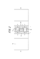
- 2 is a plan view showing a part of the rubber crawler 1 of FIG. 1 from the inner peripheral side of the elastic body 10.
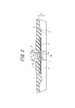
- FIG. 3 shows the rubber crawler 1 of FIG. 1 along the line AA in FIG.
- FIG. 2 is along the width direction WD of the elastic body 10 and passes through the center of the rubber film 11 in the circumferential direction CD of the elastic body 10.
- the projection region of the rubber film 11 in the width direction WD of the elastic body 10 and the projection region of the reinforcement cord 6 in the width direction WD of the elastic body 10 are mutually connected.
- the rubber film 11 may be disposed on the inner peripheral side or the outer peripheral side of the elastic body 10 with respect to the reinforcing cord 6.
- the sprocket 100 rotates while being guided by the protrusions 4 on both sides of the elastic body 10 in the width direction WD, while the teeth 101 of the sprocket 100 are partially By sequentially engaging with the sprocket holes 3, the rotational driving force is transmitted from the sprocket 100 to the rubber crawler 1.
- the rubber film 11 is repeatedly pressed and extended toward the outer peripheral side of the elastic body 10 by the teeth 101 of the sprocket 100.
- the surface 11a on the outer peripheral side of the elastic body 10 in the rubber film 11 is flat with no irregularities as shown in FIG. Since the surface 11a on the outer peripheral side of the elastic body 10 in the rubber film 11 is stretched more greatly by the teeth 101 of the sprocket 100 than the surface 11b on the inner peripheral side of the elastic body 10 in the rubber film 11, temporarily rubber When the outer peripheral surface 11a of the film 11 has irregularities, the base (root) of the irregularities is extended, so that cracks are likely to occur due to fatigue.
- the rubber crawler 1 is subjected to additional processing due to the irregularities provided on the surface of the mold for forming the rubber film 11.
- defects for example, poor appearance such as cracks in the rubber and rough skin on the rubber surface
- the surface 11a on the outer peripheral side of the elastic body 10 in the rubber film 11 is flattened, so that the crack in the rubber film 11 is caused as compared with the case where the outer peripheral surface 11a of the elastic film 10 in the rubber film 11 is uneven. Generation can be suppressed, and surface defects during production can be prevented.
- the inner peripheral surface 11b of the elastic body 10 in the rubber film 11 is recessed in a quadrangular pyramid shape.
- a quadrangular pyramid-shaped depression 11 d is formed on almost the entire inner peripheral surface 11 b of the elastic body 10 in the rubber film 11.
- a plurality of concentric rectangles drawn by broken lines on the rubber film 11 are contour lines. Due to the configuration of the outer peripheral side and inner peripheral side surfaces 11a and 11b of the elastic body 10 in the rubber film 11 as in this example, the film thickness T of the rubber film 11 is the rubber in the circumferential direction CD and the width direction WD of the elastic body 10.
- the outer portion of the rubber film 11 in the circumferential direction CD and the width direction WD of the elastic body 10 is made larger than the central portion of the film 11. More specifically, the film thickness T of the rubber film 11 is increased when viewed in all directions from the central portion of the rubber film 11 toward the outer portion.
- the “center portion of the rubber film 11 in the circumferential direction CD and the width direction WD of the elastic body 10” is a portion near the center of the rubber film 11 in the circumferential direction CD and the width direction WD of the elastic body 10.
- the “outer portion of the rubber film 11 in the circumferential direction CD and the width direction WD of the elastic body 10” is an annular portion (that is, an outer edge side portion) in the vicinity of the outer edge 11 c of the rubber film 11.
- the central portion of the rubber film 11 in the width direction WD ” are spaced apart in the circumferential direction CD and the width direction WD of the elastic body 10.
- the starting point of the crack of the rubber film 11 is higher than that of the outer portion. It tends to occur at the center. Further, when a crack occurs in the central portion of the rubber film 11, the crack growth rate from the central portion of the rubber film 11 toward the outer portion, and further toward the elastic body 10 around the rubber film 11 is determined. It can be lowered at least in the outer part. In this way, the progress of the crack of the rubber film 11 to the elastic body 10 is suppressed, the steel cord is prevented from being rusted and cut, and the life of the rubber crawler 1 can be extended.
- the inner peripheral surface 11b of the elastic film 10 in the rubber film 11 is a compressed portion.
- the film thickness T of the rubber film 11 is from the central portion of the rubber film 11 in the circumferential direction CD and the width direction WD of the elastic body 10 (more specifically, from approximately the center). ), Gradually increasing toward the outer portion of the rubber film 11 in the circumferential direction CD and the width direction WD of the elastic body 10 (more specifically, toward the outer edge 11c).
- “gradual increase” means that the rubber film 11 may be maintained constant in one or more portions on the way from the central portion toward the outer portion, but is not decreased. pointing.
- the film thickness T of the rubber film 11 is gradually increased from the central portion of the rubber film 11 toward the outer portion, so that the rubber film 11 extends from the central portion toward the outer portion, and as a result, the rubber film. Since the progress rate of the crack that progresses toward the elastic body 10 around 11 can be gradually reduced, the progress of the crack of the rubber film 11 to the elastic body 10 can be more effectively suppressed.
- the film thickness T of the rubber film 11 is changed from the central portion of the rubber film 11 in the circumferential direction CD and the width direction WD of the elastic body 10 (more specifically, From substantially the center), the elastic body 10 is continuously increased toward the outer portion of the rubber film 11 in the circumferential direction CD and the width direction WD (more specifically, toward the outer edge 11c).
- “continuously increasing” means that the rubber film 11 is constantly increased without being kept constant or decreased in the middle from the central portion toward the outer portion.
- the film thickness T of the rubber film 11 is from the central portion of the rubber film 11 in the circumferential direction CD and the width direction WD of the elastic body 10 (more specifically, from substantially the center). It is smoothly increased toward the outer portion of the rubber film 11 in the circumferential direction CD and the width direction WD (more specifically, toward the outer edge 11c).
- the configuration of the rubber film 11 is not limited to the example shown in FIGS. 2 and 3, and various modifications are possible as described below.
- the surface 11a on the outer peripheral side of the elastic body 10 in the rubber film 11 is flat, and the film thickness T of the rubber film 11 depends on the circumferential direction CD and the width direction of the elastic body 10. Assume that the outer portion of the rubber film 11 in the circumferential direction CD and the width direction WD of the elastic body 10 is larger than the central portion of the rubber film 11 in WD.
- the portion of the rubber film 11 having the minimum film thickness T is located at the approximate center of the rubber film 11 in the circumferential direction CD and the width direction WD of the elastic body 10.
- the portion of the rubber film 11 having the minimum film thickness T may be disposed at a position shifted from the approximate center of the rubber film 11 in the circumferential direction CD and the width direction WD of the elastic body 10.
- the portion of the rubber film 11 where the film thickness T is minimum can be further away from the outer edge 11c of the rubber film 11 as it is closer to the center of the rubber film 11 in the circumferential direction CD and the width direction WD of the elastic body 10. As a result, since it takes a long time for the crack to propagate to the outer edge 11c of the rubber film 11, it is preferable.
- a recess 11 d is formed on almost the entire inner peripheral surface 11 b of the elastic body 10 in the rubber film 11.
- the recess 11 d may be formed only on a part of the inner peripheral surface 11 b of the elastic body 10 in the rubber film 11.
- the shape of the recess 11d formed on the whole or a part of the inner peripheral surface 11b of the rubber film 11 is a cone other than the square pyramid as shown in the examples of FIGS. It may have an arbitrary shape such as a body (triangular pyramid, cone, etc.), a frustum (square pyramid, triangular frustum, truncated cone, etc.), or a curved surface (spherical surface, etc.).
- 4 (a) to 4 (d) are plan views showing rubber films 11 according to different modifications from the inner peripheral side of the elastic body 10, respectively.
- 5 (a) to 5 (d) are cross-sectional views along the width direction WD of the elastic body 10, showing the rubber films 11 according to different modifications.
- the film thickness T of the rubber film 11 may decrease at one or more portions on the way from the central portion to the outer portion of the rubber film 11.
- the inner peripheral surface 11b of the elastic body 10 in the rubber film 11 is configured in a substantially ripple shape.
- annular convex portions and concave portions are alternately provided substantially concentrically from the center side to the outer side of the rubber film 11, and the outer peripheral surface of the elastic body 10 in the rubber film 11.
- the height of the top of the convex portion with respect to 11a is gradually increased from the center side of the rubber film 11 in the circumferential direction CD and the width direction WD of the elastic body 10 toward the outside.
- the film thickness T of the rubber film 11 is a plurality of portions on the way from the central portion to the outer portion of the rubber film 11 (from the top of each convex portion to the concave portion).
- the total ie, when only the position of the vertex of each convex portion is viewed
- the overall shape of the recess 11d is a cone (square pyramid, triangular pyramid, cone, etc.), frustum (square pyramid, triangular pyramid).
- the shape may be any shape such as a table, a truncated cone, or the like, or a curved surface (such as a spherical surface).
- FIG. 4A shows an example in which a conical depression 11d is formed in a part of the inner peripheral surface 11b of the elastic body 10 in the rubber film 11 (a broken line on the rubber film 11).
- the concentric circles drawn in are contour lines).
- FIG. 5B shows an example in which a curved recess 11 d is formed on the inner peripheral surface 11 b of the elastic body 10 in the rubber film 11.
- the film thickness T of the rubber film 11 is different from the central portion of the rubber film 11 in the circumferential direction CD and the width direction WD of the elastic body 10 (more Specifically, from substantially the center) toward the outer portion of the rubber film 11 in the circumferential direction CD and the width direction WD of the elastic body 10 (more specifically, toward the outer edge 11c), continuously and smoothly. Has been increased.
- the recess 11d of the inner peripheral surface 11b of the elastic body 10 in the rubber film 11 may have one or more annular steps that are substantially concentric.
- the film thickness T of the rubber film 11 varies from the central portion of the rubber film 11 in the circumferential direction CD and the width direction WD of the elastic body 10 to the outer portion of the rubber film 11 in the circumferential direction CD and the width direction WD of the elastic body 10. It will be increased step by step.
- the overall shape of the recess 11d (that is, the shape when the edges of the steps of the recess 11d are smoothly connected) is a cone (square pyramid, triangular pyramid, cone, etc.), frustum (four
- the shape may be any shape such as a truncated pyramid, a triangular frustum, a truncated cone, or a curved surface (such as a spherical surface).
- the recess 11d of the inner peripheral surface 11b of the elastic body 10 in the rubber film 11 is formed in a substantially square frustum shape, and a plurality of concentric rectangles. It has a step.
- a plurality of concentric rectangles drawn with solid lines on the rubber film 11 indicate steps.
- the cross-sectional shape of the rubber film 11 is as shown in FIG.
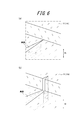
- FIG. 6 is a diagram for explaining the progress of a crack in the case where the recess 11d of the inner peripheral surface 11b of the rubber film 11 has a step as described above.
- FIG. 6A when the crack reaches a step while the crack progresses in one direction from the central portion of the rubber film 11 toward the outer portion, the thickness of the rubber film 11 becomes the step. Since the height increases, the energy required for crack growth increases. Further, since the step does not originally have a crack starting point, the crack progresses in the thickness direction TD of the elastic body 10 as shown in FIG. 6B. New energy is required for change. For these reasons, the crack growth rate is greatly reduced at the stepped portion.
- the progress rate of the crack which progresses from the central portion of the rubber film 11 toward the outer portion and thus toward the elastic body 10 around the rubber film 11, is increased. It can be gradually lowered as a whole while being relatively lowered at the portion.
- the bottom surface of the recess 11d of the inner peripheral surface 11b of the rubber film 11 gradually and spirally from the center side to the outer side of the rubber film 11 in the circumferential direction CD and the width direction WD of the elastic body 10.
- the shape may be such that the elastic body 10 faces the inner circumference side (continuously or stepwise). Thereby, the film thickness T of the rubber film 11 is changed from the central portion of the rubber film 11 in the circumferential direction CD and the width direction WD of the elastic body 10 to the outer portion of the rubber film 11 in the circumferential direction CD and the width direction WD of the elastic body 10.
- the bottom surface of the recess 11d has a circular spiral shape from the center side of the rubber film 11 in the circumferential direction CD and the width direction WD of the elastic body 10 toward the outside.
- the shape is such that it gradually (continuously) moves toward the inner peripheral side of the elastic body 10.
- the shape of the spiral is not limited to a circle as in the example of FIG. 4C, and may be an arbitrary shape such as a quadrangle (FIG. 4D) or a triangle.
- the spiral solid line drawn in FIG. 4C and FIG. 4D represents not a contour line but a step.
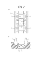
- FIG. 7A shows a rubber film 11 according to another modification
- FIG. 7B is a cross-sectional view of the rubber film 11 of FIG.
- a part of the inner peripheral surface 11 b of the elastic body 10 in the rubber film 11 is formed at the center of the rubber film 11 in the width direction WD of the elastic body 10.
- a recess 11 d that extends straight along the circumferential direction CD of the elastic body 10 is formed.
- the depression 11d of this example is formed in a substantially rectangular shape when viewed from the inner peripheral side of the elastic body 10.
- the edge part of both sides of circumferential direction CD of the hollow 11d of this example is just before reaching the outer edge 11c of the circumferential direction CD both sides of the rubber film 11 (that is, circumferential direction CD inside rather than the outer edge 11c of the circumferential direction CD both sides). ,positioned. Since the elastic body 10 is used while being wound around the sprocket 100 as shown in FIG. 1, the inner peripheral side portion of the rubber film 11 is repeatedly compressed in the circumferential direction CD of the elastic body 10. . For this reason, the crack generated in the rubber film 11 tends to progress more easily in the width direction WD of the elastic body 10 than in the circumferential direction CD of the elastic body 10. According to the example of FIG. 7A and FIG.
- the crack generation position can be the depression 11d or the vicinity thereof, and the crack once generated propagates outward in the width direction WD. Since it can suppress, the time required for a crack to progress to the outer edge 11c of both sides of the width direction WD in the rubber film 11 can be ensured long.
- the inner circumference gradually increases toward the bottom of the recess 11d toward the end of the recess 11d in the circumferential direction CD.
- a tapered surface 110d is formed so as to face the side.
- the film thickness T of the rubber film 11 gradually increases as it goes toward the end in the circumferential direction CD of the recess 11d at a portion having the tapered surface 110d.
- the depth of the recess 11d may be made constant over the entire length in the circumferential direction CD of the recess 11d without providing the tapered surface 110d on the bottom surface of the recess 11d.
- FIG. 8A shows a rubber film 11 according to still another modification
- FIG. 8B is a cross-sectional view of the rubber film 11 of FIG.
- the depression 11 d formed in a part of the inner peripheral surface 11 b of the elastic body 10 in the rubber film 11 is viewed from the inner peripheral side of the elastic body 10.
- the bottom surface of the recess 11d has a circumferential bottom surface portion 111d extending along the circumferential direction CD of the elastic body 10 at the center of the rubber film 11 in the width direction WD, and the width of the elastic body 10 from the circumferential bottom surface portion 111d.
- the length of the inclined bottom surface portion 112d along the circumferential direction CD of the elastic body 10 is gradually shortened toward the outside of the elastic body 10 in the width direction WD.
- the end portions on both sides in the circumferential direction CD of the recess 11d in this example are positioned in front of reaching the outer edges 11c on both sides in the circumferential direction CD of the rubber film 11 (that is, on the inner side in the circumferential direction CD than the outer edges 11c on both sides in the circumferential direction CD). is doing.
- the end portions on both sides in the width direction WD of the recess 11d of this example are also in front of reaching the outer edges 11c on both sides in the width direction WD of the rubber film 11 (that is, on the inner side in the width direction WD than the outer edges 11c on both sides in the width direction WD). ,positioned.
- the film thickness T of the rubber film 11 is the thinnest at the portion with the circumferential bottom surface portion 111d, and gradually increases toward the end of the recess 11d in the width direction WD at the portion with the inclined bottom surface portion 112d. Increase. According to the examples of FIGS.
- the crack generation position can be the circumferential bottom surface portion 111d where the film thickness T is the thinnest or the vicinity thereof, and the crack once generated However, since it can suppress that it progresses to the outer side of the width direction WD in the part with the inclination bottom face part 112d, it can ensure long time for a crack to advance to the outer edge 11c of the width direction WD both sides in the rubber film 11.
- the portion of the bottom surface of the recess 11d that is adjacent to both sides of the circumferential bottom surface portion 111d on both sides of the circumferential CD is the circumferential CD of the recess 11d.
- a tapered surface 110d is formed so as to gradually go to the inner peripheral side as it goes to the end.
- the thickness T of the rubber film 11 gradually increases as it goes toward the end in the circumferential direction CD of the recess 11d at a portion having the tapered surface 110d.
- portions of the bottom surface of the recess 11d adjacent to both sides of the inclined bottom surface portion 112d in the circumferential direction CD are gradually inclined toward the outside in the width direction WD of the elastic body 10 with a steeper inclination than the inclined bottom surface portion 112d.
- a tapered surface 113 d is formed toward the inner peripheral side of the elastic body 10.
- the film thickness T of the rubber film 11 gradually increases as it goes to the outside in the width direction WD of the elastic body 10 at a portion with the tapered surface 113d.
- the tapered surface 110d and / or the tapered surface 113d may not be provided on the bottom surface of the recess 11d.
- the rubber film 11 has a thickness direction TD of the elastic body 10 that does not contact the teeth 101 of the sprocket 100 when the teeth 101 of the sprocket 100 and the sprocket holes 3 engage with each other during the travel of the rubber crawler 1. It may be arranged at the position.
- the rubber crawler of the present invention can be used for a traveling device such as an agricultural machine (for example, a combine).
Landscapes
- Engineering & Computer Science (AREA)
- Chemical & Material Sciences (AREA)
- Combustion & Propulsion (AREA)
- Transportation (AREA)
- Mechanical Engineering (AREA)
Abstract
弾性体へのゴム膜の亀裂の進展を抑制し得る、ゴムクローラを提供する。本発明のゴムクローラ(1)は、スプロケット穴(3)に対して設けられたゴム膜(11)を備え、ゴム膜(11)における弾性体の外周側の面(11a)は、平坦であり、ゴム膜の膜厚(T)は、弾性体の周方向及び幅方向における該ゴム膜の中央部分よりも、弾性体の周方向及び幅方向における該ゴム膜の外側部分の方が、大きい。
Description
本発明は、ゴムクローラに関するものである。
農機具(例えばコンバイン)等の走行装置に用いられるゴムクローラとして、無端状の弾性体の外周側にラグが形成され、その内部に、一定のピッチをもって配置された芯金と、芯金を外囲いするスチールコードとが埋設され、芯金間に位置するスプロケット穴に対してゴム膜が設けられたものが、知られている(例えば、特許文献1、特許文献2)。スプロケット穴に対してゴム膜を設けることで、走行中に、スプロケット穴を通じて弾性体の内周側に土、砂利、小石等が侵入するのを防止できる。
上記のようなゴムクローラが走行する際には、スプロケットの歯がスプロケット穴と繰り返し係合するが、ゴム膜の配設位置に依っては、その度にゴム膜はスプロケットの歯によって弾性体の外周側へと押圧され伸ばされることとなる。ゴム膜に異物が刺さる場合等の外的要因や、ゴム膜の疲労によって、ゴム膜に亀裂が発生すると、その後もゴム膜がスプロケットの歯によって繰り返し押圧され伸ばされることにより、亀裂は、弾性体に向かって、特には、弾性体の幅方向に進展しやすくなる。亀裂が弾性体に達すると、弾性体内部のスチールコードの錆びひいては切断を引き起こすおそれがある。
本発明の目的は、弾性体へのゴム膜の亀裂の進展を抑制し得る、ゴムクローラを提供することにある。
本発明のゴムクローラは、外周側にラグを有する無端状の弾性体に、前記弾性体の周方向に沿って一定のピッチをもって配列された複数の芯金と、前記芯金よりも前記弾性体の外周側に配置された補強コードとが、埋設されている、ゴムクローラにおいて、前記芯金同士の間において前記弾性体に形成され、スプロケットの歯を受け入れる、スプロケット穴と、前記スプロケット穴に対して設けられたゴム膜と、を備え、前記ゴム膜における前記弾性体の外周側の面は、平坦であり、前記ゴム膜の膜厚は、前記弾性体の周方向及び幅方向における該ゴム膜の中央部分よりも、前記弾性体の周方向及び幅方向における該ゴム膜の外側部分の方が、大きいことを特徴とする。
本発明のゴムクローラによれば、弾性体へのゴム膜の亀裂の進展を抑制できる。
本発明のゴムクローラによれば、弾性体へのゴム膜の亀裂の進展を抑制できる。
前記ゴム膜の膜厚は、前記弾性体の周方向及び幅方向における該ゴム膜の中央部分から、前記弾性体の周方向及び幅方向における該ゴム膜の外側部分に向けて、徐々に増大されていることが好ましい。これによれば、弾性体へのゴム膜の亀裂の進展をより効果的に抑制できる。
前記ゴム膜の膜厚は、前記弾性体の周方向及び幅方向における該ゴム膜の中央部分から、前記弾性体の周方向及び幅方向における該ゴム膜の外側部分に向けて、段階的に増大されていると好適である。この場合、ゴム膜の上記中央部分から上記外側部分ひいては弾性体に向かって進展する亀裂の進展速度を、段の部分で比較的大きく低下させることができる。
前記ゴム膜の膜厚は、前記弾性体の周方向及び幅方向における該ゴム膜の中央部分から、前記弾性体の周方向及び幅方向における該ゴム膜の外側部分に向かう螺旋に沿って、徐々に増大されていると好適である。この場合、弾性体へのゴム膜の亀裂の進展を、さらに遅らせることができる。
本発明によれば、弾性体へのゴム膜の亀裂の進展を抑制し得る、ゴムクローラを提供することができる。
以下、本発明のゴムクローラの一実施形態を、図1~図3を参照して詳細に例示説明する。
図1は、一実施形態に係るゴムクローラ1の一部を示す、部分断面斜視図である。図1では、ゴムクローラ1が、ゴムクローラ1に回転駆動力を伝達するスプロケット100に巻き掛けられている。駆動輪となるスプロケット100と従動輪となるアイドラ(図示せず)との間には、ゴムクローラ1の荷重を支持しつつゴムクローラ1をガイドするための転輪102が、設けられている。
図1は、一実施形態に係るゴムクローラ1の一部を示す、部分断面斜視図である。図1では、ゴムクローラ1が、ゴムクローラ1に回転駆動力を伝達するスプロケット100に巻き掛けられている。駆動輪となるスプロケット100と従動輪となるアイドラ(図示せず)との間には、ゴムクローラ1の荷重を支持しつつゴムクローラ1をガイドするための転輪102が、設けられている。
ゴムクローラ1は、無端状のゴム等の弾性体10を有しており、弾性体10は、その外周面に、路面に作用する複数のラグ2を有している。図1の例におけるラグ2は、弾性体10の幅方向WD(ひいては、ゴムクローラ1の幅方向)にまっすぐ延在する形状からなるが、他の形状からなるものでもよい。弾性体10には、弾性体10の周方向CD(ひいては、ゴムクローラ1の周方向)に沿って一定のピッチをもって配列された複数の芯金5と、芯金5よりも弾性体10の外周側に配置された複数の補強コード6とが、埋設されている。
図1の例では、弾性体10の厚さ方向TD(ひいては、ゴムクローラ1の厚さ方向)へのラグ2の投影領域と、弾性体10の厚さ方向TDへの芯金5の投影領域とが、互いに重複している。
図1の例では、弾性体10の厚さ方向TD(ひいては、ゴムクローラ1の厚さ方向)へのラグ2の投影領域と、弾性体10の厚さ方向TDへの芯金5の投影領域とが、互いに重複している。
芯金5は、弾性体10の幅方向WDに延在しており、弾性体10の幅方向WDにおける芯金5の中央部分から弾性体10の内周側に向けて突出する一対の角部5aを有している。一対の角部5aは、弾性体10の幅方向WDに互いから離間されている。芯金5の角部5aと、角部5aを覆う弾性体10の被覆部分とで、弾性体10の内周側へ突出する突起部4を構成している。ただし、芯金5の角部5aは弾性体10により覆われずに露出していてもよく、その場合、芯金の角部5aのみで突起部4が構成される。
補強コード6は、弾性体10の周方向CDへの延びを規制しつつ、スプロケット100から受ける駆動力に基づくゴムクローラ1のスムーズな回転を補助する。複数の補強コード6は、それぞれ弾性体10の周方向CDに沿って延在するとともに、互いに弾性体10の幅方向WDに沿って配列されており、芯金5のうちの、一対の角部5aから弾性体10の幅方向WDの外側の部分を、外囲いしている。補強コード6の材料は、本例ではスチールであるが、有機繊維等の他の材料を用いてもよい。
ゴムクローラ1は、弾性体10の周方向CDにおける芯金5同士の間において弾性体10の内周面に形成され、スプロケット100の歯101を受け入れる、スプロケット穴3と、スプロケット穴3に対して設けられたゴム膜11とを、さらに備えている(図2及び図3参照)。スプロケット穴3は、貫通していない窪みとして構成されており、その底面は、ゴム膜11における弾性体10の内周側の面11bによって形成されている。ゴム膜11は、弾性体10と一体に形成されている。
なお、図2は、図1のゴムクローラ1の一部を、弾性体10の内周側から示す平面図であり、図3は、図1のゴムクローラ1を、図2のA-A線に沿う断面により示す図である。図2のA-A線は、弾性体10の幅方向WDに沿うとともに、弾性体10の周方向CDにおけるゴム膜11の中心を通っている。
なお、図2は、図1のゴムクローラ1の一部を、弾性体10の内周側から示す平面図であり、図3は、図1のゴムクローラ1を、図2のA-A線に沿う断面により示す図である。図2のA-A線は、弾性体10の幅方向WDに沿うとともに、弾性体10の周方向CDにおけるゴム膜11の中心を通っている。
図3の断面図に示すように、本例では、弾性体10の幅方向WDへのゴム膜11の投影領域と、弾性体10の幅方向WDへの補強コード6の投影領域とが、互いに重複している。しかし、ゴム膜11は、補強コード6よりも、弾性体10の内周側又は外周側に配置されていてもよい。
このように構成されたゴムクローラ1が走行する際、スプロケット100は、弾性体10の幅方向WDの両側で突起部4によってガイドされながら回転し、その間、スプロケット100の歯101が、一部のスプロケット穴3と順次係合することにより、スプロケット100からゴムクローラ1へと回転駆動力が伝達される。ゴムクローラ1の走行中、ゴム膜11は、スプロケット100の歯101によって、弾性体10の外周側へと繰り返し押圧され伸ばされる。
以下、本例におけるゴム膜11の構成について、図2の平面図及び図3の断面図を参照しながら、さらに詳細に説明する。
本実施形態において、ゴム膜11における弾性体10の外周側の面11aは、図3に示すように、凹凸が無く、平坦に形成されている。
ゴム膜11における弾性体10の外周側の面11aは、ゴム膜11における弾性体10の内周側の面11bと比べて、スプロケット100の歯101によってより大きく引き伸ばされることとなるので、仮にゴム膜11における外周側の面11aに凹凸がある場合、凹凸の基部(根本)が伸ばされる為、疲労により、亀裂が生じ易くなる。また、ゴム膜11における弾性体10の外周側の面11aに凹凸が設けられる場合、ゴムクローラ1の製造時において、ゴム膜11形成用の金型の表面に設けられた凹凸に起因して加硫時にゴムの流れが妨げられる結果、ゴム膜11における弾性体10の外周側の面11aに欠陥(例えば、ゴムの亀裂やゴム表面の肌荒れ等の外観不良)が現れやすい。
よって、ゴム膜11における弾性体10の外周側の面11aを平坦とすることにより、ゴム膜11における弾性体10の外周側の面11aに凹凸がある場合に比べて、ゴム膜11への亀裂の発生を抑制できるとともに、製造時での表面欠陥を防止できる。
一方、本実施形態において、ゴム膜11における弾性体10の内周側の面11bは、四角錐状に窪んでいる。言い換えれば、ゴム膜11における弾性体10の内周側の面11bのほぼ全体に、四角錐状の窪み11dが形成されている。なお、図2において、ゴム膜11上に破線で描かれた複数の同心の長方形は、等高線である。
本例のようなゴム膜11における弾性体10の外周側及び内周側の面11a、11bの構成により、ゴム膜11の膜厚Tは、弾性体10の周方向CD及び幅方向WDにおけるゴム膜11の中央部分よりも、弾性体10の周方向CD及び幅方向WDにおけるゴム膜11の外側部分の方が、大きくされている。より具体的に、ゴム膜11の膜厚Tは、ゴム膜11の該中央部分から該外側部分に向かう全ての方向で観たときに、増大されている。
なお、「弾性体10の周方向CD及び幅方向WDにおけるゴム膜11の中央部分」とは、弾性体10の周方向CD及び幅方向WDにおけるゴム膜11の中心近傍の部分である。「弾性体10の周方向CD及び幅方向WDにおけるゴム膜11の外側部分」とは、ゴム膜11の外縁11c近傍の環状部分(すなわち外縁側部分)であり、「弾性体10の周方向CD及び幅方向WDにおけるゴム膜11の中央部分」に対して弾性体10の周方向CD及び幅方向WDに離間した位置にある。
ゴム膜11の上記中央部分での膜厚Tよりも、ゴム膜11の上記外側部分での膜厚Tの方が、大きいことにより、ゴム膜11の亀裂の起点が、該外側部分よりも該中央部分で生じ易くなる。さらに、ゴム膜11の該中央部分に亀裂が生じた場合に、ゴム膜11の該中央部分から該外側部分に向かう、ひいてはゴム膜11の周りの弾性体10に向かう、亀裂の進展速度を、少なくとも該外側部分で、低下させることができる。このようにして、弾性体10へのゴム膜11の亀裂の進展を抑制し、スチールコードの錆びや切断を防止し、ひいてはゴムクローラ1の長寿命化が可能となる。
また、ゴム膜11における弾性体10の内周側の面11bは、ゴム膜11における弾性体10の外周側の面11aとは異なり、圧縮される部分であるため、本実施形態のようにゴム膜11の内周側に凹凸を設けることにより、圧縮によるゴムの歪みを低減でき、耐疲労性が向上するので、亀裂発生を効果的に抑制できる。
また、ゴム膜11における弾性体10の内周側の面11bは、ゴム膜11における弾性体10の外周側の面11aとは異なり、圧縮される部分であるため、本実施形態のようにゴム膜11の内周側に凹凸を設けることにより、圧縮によるゴムの歪みを低減でき、耐疲労性が向上するので、亀裂発生を効果的に抑制できる。
さらに、図2及び図3に示す例では、ゴム膜11の膜厚Tが、弾性体10の周方向CD及び幅方向WDにおけるゴム膜11の中央部分から(より具体的には、略中心から)、弾性体10の周方向CD及び幅方向WDにおけるゴム膜11の外側部分に向けて(より具体的には、外縁11cに向けて)、徐々に増大されている。
ここで、「徐々に増大」とは、ゴム膜11の上記中央部分から上記外側部分に向かう途中の1つ以上の部分で、一定に維持されてもよいが、減少されることはないことを指している。
ゴム膜11の膜厚Tが、ゴム膜11の該中央部分から該外側部分に向けて、徐々に増大されることにより、ゴム膜11の該中央部分から該外側部分に向かって、ひいてはゴム膜11の周りの弾性体10に向かって進展する、亀裂の進展速度を、徐々に低下させることができるので、弾性体10へのゴム膜11の亀裂の進展をより効果的に抑制できる。
ここで、「徐々に増大」とは、ゴム膜11の上記中央部分から上記外側部分に向かう途中の1つ以上の部分で、一定に維持されてもよいが、減少されることはないことを指している。
ゴム膜11の膜厚Tが、ゴム膜11の該中央部分から該外側部分に向けて、徐々に増大されることにより、ゴム膜11の該中央部分から該外側部分に向かって、ひいてはゴム膜11の周りの弾性体10に向かって進展する、亀裂の進展速度を、徐々に低下させることができるので、弾性体10へのゴム膜11の亀裂の進展をより効果的に抑制できる。
より具体的に、図2及び図3に示す例では、ゴム膜11の膜厚Tが、弾性体10の周方向CD及び幅方向WDにおけるゴム膜11の中央部分から(より具体的には、略中心から)、弾性体10の周方向CD及び幅方向WDにおけるゴム膜11の外側部分に向けて(より具体的には、外縁11cに向けて)、連続的に増大されている。
ここで、「連続的に増大」とは、ゴム膜11の上記中央部分から上記外側部分に向かう途中で、一定に維持されたり減少されたりすること無く、常に増大され続けることを指している。
さらに、この例では、ゴム膜11の膜厚Tが、弾性体10の周方向CD及び幅方向WDにおけるゴム膜11の中央部分から(より具体的には、略中心から)、弾性体10の周方向CD及び幅方向WDにおけるゴム膜11の外側部分に向けて(より具体的には、外縁11cに向けて)、滑らかに増大されている。
ここで、「連続的に増大」とは、ゴム膜11の上記中央部分から上記外側部分に向かう途中で、一定に維持されたり減少されたりすること無く、常に増大され続けることを指している。
さらに、この例では、ゴム膜11の膜厚Tが、弾性体10の周方向CD及び幅方向WDにおけるゴム膜11の中央部分から(より具体的には、略中心から)、弾性体10の周方向CD及び幅方向WDにおけるゴム膜11の外側部分に向けて(より具体的には、外縁11cに向けて)、滑らかに増大されている。
ゴム膜11の構成は、図2及び図3に示す例に限られず、以下に説明するように、様々な変形例が可能である。なお、以下に説明する各変形例でも、ゴム膜11における弾性体10の外周側の面11aは平坦であり、また、ゴム膜11の膜厚Tは、弾性体10の周方向CD及び幅方向WDにおけるゴム膜11の中央部分よりも、弾性体10の周方向CD及び幅方向WDにおけるゴム膜11の外側部分の方が、大きいものとする。
図2及び図3に示す例では、ゴム膜11のうち膜厚Tが最小となる部分が、弾性体10の周方向CD及び幅方向WDにおけるゴム膜11の略中心に位置している。しかし、ゴム膜11のうち膜厚Tが最小となる部分は、弾性体10の周方向CD及び幅方向WDにおけるゴム膜11の略中心からずれた位置に配置されていてもよい。ただし、ゴム膜11のうち膜厚Tが最小となる部分は、弾性体10の周方向CD及び幅方向WDにおけるゴム膜11の中心に近いほど、ゴム膜11の外縁11cから遠ざけることができ、ひいてはゴム膜11の外縁11cまで亀裂が進展するのにかかる時間を長く確保できるので、好適となる。
また、図2及び図3に示す例では、ゴム膜11における弾性体10の内周側の面11bのほぼ全体に、窪み11dが形成されている。しかし、ゴム膜11における弾性体10の内周側の面11bの一部のみに、窪み11dを形成してもよい。
ゴム膜11における弾性体10の内周側の面11bの全体又は一部に形成される窪み11dの形状は、図2及び図3の例のような四角錐の代わりに、四角錐以外の錐体(三角錐や円錐等)、錐台(四角錐台、三角錐台、円錐台等)、又は曲面(球面等)等、任意の形状としてもよい。
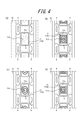
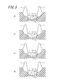
図4(a)~図4(d)は、それぞれ別々の変形例に係るゴム膜11を、弾性体10の内周側から示す、平面図である。図5(a)~図5(d)は、それぞれ別々の変形例に係るゴム膜11を示す、弾性体10の幅方向WDに沿う断面図である。
ゴム膜11の膜厚Tは、ゴム膜11の上記中央部分から上記外側部分に向かう途中の1つ以上の部分で、減少してもよい。例えば、図5(a)の断面図で示す例では、ゴム膜11における弾性体10の内周側の面11bが、略リプル状に構成されており、より具体的には、弾性体10の周方向CD及び幅方向WDにおけるゴム膜11の中心側から外側に向かって、環状の凸部及び凹部が略同心状に交互に設けられており、ゴム膜11における弾性体10の外周側の面11aに対する凸部の頂点の高さは、弾性体10の周方向CD及び幅方向WDにおけるゴム膜11の中心側から外側に向かって、徐々に増大されている。このような構成により、図5(a)の例では、ゴム膜11の膜厚Tが、ゴム膜11の上記中央部分から上記外側部分に向かう途中の複数の部分(各凸部の頂点から凹部の底までの部分)で減少するが、全体としては(すなわち、各凸部の頂点の位置だけを観た場合)、ゴム膜11の上記中央部分から上記外側部分に向けて、徐々に増大されている。この場合、窪み11dの全体的な形状(すなわち、各凸部の頂点だけを観た場合の形状)は、錐体(四角錐、三角錐、円錐等)、錐台(四角錐台、三角錐台、円錐台等)、又は曲面(球面等)等、任意の形状としてよい。
ゴム膜11の膜厚Tは、ゴム膜11の上記中央部分から上記外側部分に向かう途中の1つ以上の部分で、減少してもよい。例えば、図5(a)の断面図で示す例では、ゴム膜11における弾性体10の内周側の面11bが、略リプル状に構成されており、より具体的には、弾性体10の周方向CD及び幅方向WDにおけるゴム膜11の中心側から外側に向かって、環状の凸部及び凹部が略同心状に交互に設けられており、ゴム膜11における弾性体10の外周側の面11aに対する凸部の頂点の高さは、弾性体10の周方向CD及び幅方向WDにおけるゴム膜11の中心側から外側に向かって、徐々に増大されている。このような構成により、図5(a)の例では、ゴム膜11の膜厚Tが、ゴム膜11の上記中央部分から上記外側部分に向かう途中の複数の部分(各凸部の頂点から凹部の底までの部分)で減少するが、全体としては(すなわち、各凸部の頂点の位置だけを観た場合)、ゴム膜11の上記中央部分から上記外側部分に向けて、徐々に増大されている。この場合、窪み11dの全体的な形状(すなわち、各凸部の頂点だけを観た場合の形状)は、錐体(四角錐、三角錐、円錐等)、錐台(四角錐台、三角錐台、円錐台等)、又は曲面(球面等)等、任意の形状としてよい。
図4(a)の平面図は、ゴム膜11における弾性体10の内周側の面11bの一部に、円錐状の窪み11dが形成された例を示している(ゴム膜11上に破線で描かれた複数の同心円は、等高線である)。
一方、図5(b)の断面図は、ゴム膜11における弾性体10の内周側の面11bに、曲面状の窪み11dが形成された例を示している。
図4(a)の例及び図5(b)の例では、いずれも、ゴム膜11の膜厚Tが、弾性体10の周方向CD及び幅方向WDにおけるゴム膜11の中央部分から(より具体的には、略中心から)、弾性体10の周方向CD及び幅方向WDにおけるゴム膜11の外側部分に向けて(より具体的には、外縁11cに向けて)、連続的かつ滑らかに増大されている。
一方、図5(b)の断面図は、ゴム膜11における弾性体10の内周側の面11bに、曲面状の窪み11dが形成された例を示している。
図4(a)の例及び図5(b)の例では、いずれも、ゴム膜11の膜厚Tが、弾性体10の周方向CD及び幅方向WDにおけるゴム膜11の中央部分から(より具体的には、略中心から)、弾性体10の周方向CD及び幅方向WDにおけるゴム膜11の外側部分に向けて(より具体的には、外縁11cに向けて)、連続的かつ滑らかに増大されている。
ゴム膜11における弾性体10の内周側の面11bの窪み11dは、略同心の1つ以上の環状の段を有していてもよい。この場合、ゴム膜11の膜厚Tは、弾性体10の周方向CD及び幅方向WDにおけるゴム膜11の中央部分から、弾性体10の周方向CD及び幅方向WDにおけるゴム膜11の外側部分に向けて、段階的に増大することとなる。なお、窪み11dの全体的な形状(すなわち、窪み11dの各段の縁(エッジ)を滑らかにつなげたときの形状)は、錐体(四角錐、三角錐、円錐等)、錐台(四角錐台、三角錐台、円錐台等)、又は曲面(球面等)等、任意の形状としてよい。
例えば、図4(b)の平面図に示す例では、ゴム膜11における弾性体10の内周側の面11bの窪み11dが、略四角錐台状に形成されており、同心の複数の長方形状の段を有している。なお、図4(b)において、ゴム膜11上に実線で描かれた複数の同心の長方形は、段を示している。図4(b)の例の場合、ゴム膜11の断面形状は、図5(c)のようになる。
例えば、図4(b)の平面図に示す例では、ゴム膜11における弾性体10の内周側の面11bの窪み11dが、略四角錐台状に形成されており、同心の複数の長方形状の段を有している。なお、図4(b)において、ゴム膜11上に実線で描かれた複数の同心の長方形は、段を示している。図4(b)の例の場合、ゴム膜11の断面形状は、図5(c)のようになる。
図6は、ゴム膜11における弾性体10の内周側の面11bの窪み11dが上述したような段を有する場合における、亀裂の進展について説明するための図である。図6(a)に示すように、ゴム膜11の上記中央部分から上記外側部分に向けて亀裂がある一方向に進展する間、亀裂が段に到達すると、ゴム膜11の肉厚が段の高さ分増大するため、亀裂の進展に要するエネルギーが増大する。さらに、段には亀裂の起点がもともと無いため、亀裂は、図6(b)に示すように、弾性体10の厚さ方向TDに進展することとなるが、このような亀裂の進展方向の変化に要するエネルギーが新たに必要となる。このような理由から、亀裂の進展速度は、段の部分で大きく低下する。
したがって、窪み11dに段を設けることにより、ゴム膜11の上記中央部分から上記外側部分に向かって、ひいてはゴム膜11の周りの弾性体10に向かって進展する、亀裂の進展速度を、段の部分で比較的大きく低下させつつ、全体として徐々に低下させることができる。
したがって、窪み11dに段を設けることにより、ゴム膜11の上記中央部分から上記外側部分に向かって、ひいてはゴム膜11の周りの弾性体10に向かって進展する、亀裂の進展速度を、段の部分で比較的大きく低下させつつ、全体として徐々に低下させることができる。
ゴム膜11における弾性体10の内周側の面11bの窪み11dの底面は、弾性体10の周方向CD及び幅方向WDにおけるゴム膜11の中心側から外側に向かって、螺旋状に、徐々に(連続的又は段階的に)弾性体10の内周側に向かうような形状でもよい。これにより、ゴム膜11の膜厚Tは、弾性体10の周方向CD及び幅方向WDにおけるゴム膜11の中央部分から、弾性体10の周方向CD及び幅方向WDにおけるゴム膜11の外側部分に向かう、螺旋に沿って、徐々に(連続的又は段階的に)増大されることとなる。この場合、ゴム膜11の亀裂を、ゴム膜11の上記中央部分から上記外側部分ひいては弾性体10に向かって、螺旋状に進展させることができるので、亀裂の弾性体10までの進展をより遅らせることができる。
例えば、図4(c)の平面図に示す例では、窪み11dの底面が、弾性体10の周方向CD及び幅方向WDにおけるゴム膜11の中心側から外側に向かって、円形の螺旋状に、徐々に(連続的に)弾性体10の内周側に向かうような形状からなる。図4(c)の例における断面図は、図5(d)のようになる。
ただし、螺旋の形状は、図4(c)の例のような円形に限られず、四角形(図4(d))や三角形等、任意の形状とすることができる。
なお、図4(c)及び図4(d)に描かれた螺旋状の実線は、等高線ではなく、段を表している。
例えば、図4(c)の平面図に示す例では、窪み11dの底面が、弾性体10の周方向CD及び幅方向WDにおけるゴム膜11の中心側から外側に向かって、円形の螺旋状に、徐々に(連続的に)弾性体10の内周側に向かうような形状からなる。図4(c)の例における断面図は、図5(d)のようになる。
ただし、螺旋の形状は、図4(c)の例のような円形に限られず、四角形(図4(d))や三角形等、任意の形状とすることができる。
なお、図4(c)及び図4(d)に描かれた螺旋状の実線は、等高線ではなく、段を表している。
図7(a)の平面図は、さらに別の変形例に係るゴム膜11を示しており、図7(b)は、図7(a)のゴム膜11の断面図である。図7(a)及び図7(b)に示す例では、ゴム膜11における弾性体10の内周側の面11bの一部に、弾性体10の幅方向WDにおけるゴム膜11の中心で、弾性体10の周方向CDに沿ってまっすぐ延在する、窪み11dが形成されている。本例の窪み11dは、弾性体10の内周側から観たときに略長方形状に形成されている。また、本例の窪み11dの、周方向CDの両側の端部は、ゴム膜11の周方向CD両側の外縁11cに至る手前(すなわち周方向CD両側の外縁11cよりも周方向CD内側)に、位置している。
弾性体10は、図1に示すようにスプロケット100に巻き掛けられて使用されることから、ゴム膜11の内周側部分は、弾性体10の周方向CDに繰り返して圧縮されることとなる。このため、ゴム膜11に生じた亀裂は、弾性体10の周方向CDよりも弾性体10の幅方向WDに、進展しやすいという傾向がある。図7(a)及び図7(b)の例によれば、亀裂の発生位置を窪み11d又はその近傍とすることができ、また、いったん発生した亀裂が、幅方向WD外側に進展するのを抑制することが出来るため、ゴム膜11における幅方向WD両側の外縁11cまで亀裂が進展するのにかかる時間を、長く確保できる。
弾性体10は、図1に示すようにスプロケット100に巻き掛けられて使用されることから、ゴム膜11の内周側部分は、弾性体10の周方向CDに繰り返して圧縮されることとなる。このため、ゴム膜11に生じた亀裂は、弾性体10の周方向CDよりも弾性体10の幅方向WDに、進展しやすいという傾向がある。図7(a)及び図7(b)の例によれば、亀裂の発生位置を窪み11d又はその近傍とすることができ、また、いったん発生した亀裂が、幅方向WD外側に進展するのを抑制することが出来るため、ゴム膜11における幅方向WD両側の外縁11cまで亀裂が進展するのにかかる時間を、長く確保できる。
なお、図7(a)及び図7(b)の例では、窪み11dの周方向CD両側の端部において、窪み11dの底面に、窪み11dの周方向CDの端に向かうにつれて徐々に内周側に向かうような、テーパ面110dが形成されている。このため、ゴム膜11の膜厚Tは、テーパ面110dのある部分で、窪み11dの周方向CDの端に向かうにつれて徐々に増大する。ただし、窪み11dの底面にテーパ面110dを設けずに、窪み11dの周方向CDの全長にわたって、窪み11dの深さを一定にしてもよい。
図8(a)の平面図は、さらに別の変形例に係るゴム膜11を示しており、図8(b)は、図8(a)のゴム膜11の断面図である。図8(a)及び図8(b)に示す例では、ゴム膜11における弾性体10の内周側の面11bの一部に形成された窪み11dが、弾性体10の内周側から観たときに略ひし形状に形成されている。窪み11dの底面は、幅方向WDにおけるゴム膜11の中心で弾性体10の周方向CDに沿って延在する、周方向底面部111dを有するとともに、周方向底面部111dから弾性体10の幅方向WD外側に向かうにつれて徐々に弾性体10の内周側へ向かって傾斜する、傾斜底面部112dを有する。傾斜底面部112dの、弾性体10の周方向CDに沿う長さは、弾性体10の幅方向WD外側に向かうにつれて徐々に短くなるようにされている。本例の窪み11dの、周方向CDの両側の端部は、ゴム膜11の周方向CD両側の外縁11cに至る手前(すなわち周方向CD両側の外縁11cよりも周方向CD内側)に、位置している。また、本例の窪み11dの、幅方向WDの両側の端部も、ゴム膜11の幅方向WD両側の外縁11cに至る手前(すなわち幅方向WD両側の外縁11cよりも幅方向WD内側)に、位置している。この構成によれば、ゴム膜11の膜厚Tは、周方向底面部111dのある部分で最も薄くなり、傾斜底面部112dのある部分で、窪み11dの幅方向WDの端に向かうにつれて徐々に増大する。
図8(a)及び図8(b)の例によれば、亀裂の発生位置を、最も膜厚Tが薄くなる周方向底面部111d又はその近傍とすることができ、また、いったん発生した亀裂が、幅方向WD外側に進展するのを、傾斜底面部112dのある部分で抑制できるため、ゴム膜11における幅方向WD両側の外縁11cまで亀裂が進展するのにかかる時間を、長く確保できる。
図8(a)及び図8(b)の例によれば、亀裂の発生位置を、最も膜厚Tが薄くなる周方向底面部111d又はその近傍とすることができ、また、いったん発生した亀裂が、幅方向WD外側に進展するのを、傾斜底面部112dのある部分で抑制できるため、ゴム膜11における幅方向WD両側の外縁11cまで亀裂が進展するのにかかる時間を、長く確保できる。
なお、図8(a)及び図8(b)の例では、窪み11dの底面のうち、周方向底面部111dに対して周方向CD両側に隣接する部分には、窪み11dの周方向CDの端に向かうにつれて徐々に内周側に向かうような、テーパ面110dが形成されている。ゴム膜11の膜厚Tは、テーパ面110dのある部分で、窪み11dの周方向CDの端に向かうにつれて徐々に増大する。
また、窪み11dの底面のうち、傾斜底面部112dの周方向CDの両側に隣接する部分には、傾斜底面部112dよりも急な傾きで、弾性体10の幅方向WD外側に向かうにつれて徐々に弾性体10の内周側へ向かう、テーパ面113dが形成されている。ゴム膜11の膜厚Tは、テーパ面113dのある部分で、弾性体10の幅方向WD外側に向かうにつれて徐々に増大する。
ただし、窪み11dの底面には、上記テーパ面110d及び/又はテーパ面113dを設けなくてもよい。
また、窪み11dの底面のうち、傾斜底面部112dの周方向CDの両側に隣接する部分には、傾斜底面部112dよりも急な傾きで、弾性体10の幅方向WD外側に向かうにつれて徐々に弾性体10の内周側へ向かう、テーパ面113dが形成されている。ゴム膜11の膜厚Tは、テーパ面113dのある部分で、弾性体10の幅方向WD外側に向かうにつれて徐々に増大する。
ただし、窪み11dの底面には、上記テーパ面110d及び/又はテーパ面113dを設けなくてもよい。
なお、ゴム膜11は、ゴムクローラ1の走行中にスプロケット100の歯101とスプロケット穴3とが互いに係合する際に、スプロケット100の歯101に当たらないような弾性体10の厚さ方向TDの位置に、配置されてもよい。
本発明のゴムクローラは、農機具(例えばコンバイン)等の走行装置に利用することができる。
1:ゴムクローラ、 2:ラグ、 3:スプロケット穴、 4:突起部、 5:芯金、 5a:角部、 6:補強コード、 10:弾性体、 11:ゴム膜、 11a:ゴム膜における弾性体の外周側の面、 11b:ゴム膜における弾性体の内周側の面、 11c:弾性体の内周側から平面視したときのゴム膜の外縁、 11d:ゴム膜の窪み、 100:スプロケット、 101:スプロケットの歯、 102:転輪、 110d、113d:テーパ面、 111d:周方向底面部、 112d:傾斜底面部、 CD:弾性体の周方向、 TD:弾性体の厚さ方向、 WD:弾性体の幅方向
Claims (4)
- 無端状の弾性体に、前記弾性体の周方向に沿って一定のピッチをもって配列された複数の芯金と、前記芯金よりも前記弾性体の外周側に配置された補強コードとが、埋設されている、ゴムクローラにおいて、
前記芯金同士の間において前記弾性体に形成され、スプロケットの歯を受け入れる、スプロケット穴と、
前記スプロケット穴に対して設けられたゴム膜と、
を備え、
前記ゴム膜における前記弾性体の外周側の面は、平坦であり、
前記ゴム膜の膜厚は、前記弾性体の周方向及び幅方向における該ゴム膜の中央部分よりも、前記弾性体の周方向及び幅方向における該ゴム膜の外側部分の方が、大きいことを特徴とする、ゴムクローラ。 - 前記ゴム膜の膜厚は、前記弾性体の周方向及び幅方向における該ゴム膜の中央部分から、前記弾性体の周方向及び幅方向における該ゴム膜の外側部分に向けて、徐々に増大されている、請求項1に記載のゴムクローラ。
- 前記ゴム膜の膜厚は、前記弾性体の周方向及び幅方向における該ゴム膜の中央部分から、前記弾性体の周方向及び幅方向における該ゴム膜の外側部分に向けて、段階的に増大されている、請求項1又は2に記載のゴムクローラ。
- 前記ゴム膜の膜厚は、前記弾性体の周方向及び幅方向における該ゴム膜の中央部分から、前記弾性体の周方向及び幅方向における該ゴム膜の外側部分に向かう螺旋に沿って、徐々に増大されている、請求項1又は3に記載のゴムクローラ。
Priority Applications (2)
| Application Number | Priority Date | Filing Date | Title |
|---|---|---|---|
| JP2016532450A JP6549575B2 (ja) | 2014-07-11 | 2015-07-10 | ゴムクローラ |
| CN201580037320.7A CN106488870B (zh) | 2014-07-11 | 2015-07-10 | 橡胶履带 |
Applications Claiming Priority (2)
| Application Number | Priority Date | Filing Date | Title |
|---|---|---|---|
| JP2014143422 | 2014-07-11 | ||
| JP2014-143422 | 2014-07-11 |
Publications (1)
| Publication Number | Publication Date |
|---|---|
| WO2016006259A1 true WO2016006259A1 (ja) | 2016-01-14 |
Family
ID=55063907
Family Applications (1)
| Application Number | Title | Priority Date | Filing Date |
|---|---|---|---|
| PCT/JP2015/003508 Ceased WO2016006259A1 (ja) | 2014-07-11 | 2015-07-10 | ゴムクローラ |
Country Status (3)
| Country | Link |
|---|---|
| JP (1) | JP6549575B2 (ja) |
| CN (1) | CN106488870B (ja) |
| WO (1) | WO2016006259A1 (ja) |
Citations (2)
| Publication number | Priority date | Publication date | Assignee | Title |
|---|---|---|---|---|
| JP2003237647A (ja) * | 2002-02-14 | 2003-08-27 | Ohtsu Tire & Rubber Co Ltd :The | ゴムクローラ |
| JP2009107442A (ja) * | 2007-10-29 | 2009-05-21 | Bridgestone Corp | ゴムクローラ |
Family Cites Families (2)
| Publication number | Priority date | Publication date | Assignee | Title |
|---|---|---|---|---|
| JP2002104258A (ja) * | 2000-10-02 | 2002-04-10 | Komatsu Ltd | 弾性体履板の芯金 |
| JP2009292204A (ja) * | 2008-06-03 | 2009-12-17 | Bridgestone Corp | ゴムクローラ |
-
2015
- 2015-07-10 JP JP2016532450A patent/JP6549575B2/ja not_active Expired - Fee Related
- 2015-07-10 CN CN201580037320.7A patent/CN106488870B/zh not_active Expired - Fee Related
- 2015-07-10 WO PCT/JP2015/003508 patent/WO2016006259A1/ja not_active Ceased
Patent Citations (2)
| Publication number | Priority date | Publication date | Assignee | Title |
|---|---|---|---|---|
| JP2003237647A (ja) * | 2002-02-14 | 2003-08-27 | Ohtsu Tire & Rubber Co Ltd :The | ゴムクローラ |
| JP2009107442A (ja) * | 2007-10-29 | 2009-05-21 | Bridgestone Corp | ゴムクローラ |
Also Published As
| Publication number | Publication date |
|---|---|
| CN106488870B (zh) | 2019-06-21 |
| CN106488870A (zh) | 2017-03-08 |
| JP6549575B2 (ja) | 2019-07-24 |
| JPWO2016006259A1 (ja) | 2017-04-27 |
Similar Documents
| Publication | Publication Date | Title |
|---|---|---|
| US2476828A (en) | Endless band track | |
| JP6101329B2 (ja) | ゴムクローラ及び車両 | |
| CN102686475A (zh) | 链轮和具有该链轮的橡胶履带组装体 | |
| US20180170117A1 (en) | Tire tread pattern provided with anti-stone structure | |
| JP5050443B2 (ja) | 非空気入りタイヤ | |
| US9185992B2 (en) | Connecting structure for inflatable products | |
| JPWO2016006259A1 (ja) | ゴムクローラ | |
| JP5832791B2 (ja) | クローラ用芯金、弾性クローラ | |
| TWI776043B (zh) | 彈性履帶 | |
| JP2013086727A (ja) | 弾性クローラ | |
| JP5788662B2 (ja) | 弾性クローラ | |
| JP6616641B2 (ja) | 弾性クローラおよび弾性クローラ装置 | |
| JP2008230330A (ja) | ゴムクローラ | |
| WO2016001995A1 (ja) | 空気入りタイヤ | |
| CN102730094A (zh) | 橡胶履带 | |
| JP5808633B2 (ja) | 弾性クローラ及びクローラ走行装置 | |
| JP6763152B2 (ja) | ゴムクローラ | |
| JP2010132136A (ja) | クローラ走行装置 | |
| JP6747148B2 (ja) | 弾性クローラ | |
| JP5193742B2 (ja) | ゴムクローラ | |
| JP5731242B2 (ja) | 農業用タイヤ | |
| JP2007176208A (ja) | 弾性履帯 | |
| JP7102927B2 (ja) | 弾性クローラ及びクローラ式走行体 | |
| JP2016187975A (ja) | ゴムクローラ | |
| JP7183644B2 (ja) | 弾性クローラ |
Legal Events
| Date | Code | Title | Description |
|---|---|---|---|
| 121 | Ep: the epo has been informed by wipo that ep was designated in this application |
Ref document number: 15819609 Country of ref document: EP Kind code of ref document: A1 |
|
| ENP | Entry into the national phase |
Ref document number: 2016532450 Country of ref document: JP Kind code of ref document: A |
|
| NENP | Non-entry into the national phase |
Ref country code: DE |
|
| 122 | Ep: pct application non-entry in european phase |
Ref document number: 15819609 Country of ref document: EP Kind code of ref document: A1 |