WO2016002933A1 - モニタリング装置 - Google Patents
モニタリング装置 Download PDFInfo
- Publication number
- WO2016002933A1 WO2016002933A1 PCT/JP2015/069277 JP2015069277W WO2016002933A1 WO 2016002933 A1 WO2016002933 A1 WO 2016002933A1 JP 2015069277 W JP2015069277 W JP 2015069277W WO 2016002933 A1 WO2016002933 A1 WO 2016002933A1
- Authority
- WO
- WIPO (PCT)
- Prior art keywords
- variable
- value
- display
- unit
- input
- Prior art date
- Legal status (The legal status is an assumption and is not a legal conclusion. Google has not performed a legal analysis and makes no representation as to the accuracy of the status listed.)
- Ceased
Links
Images


Classifications
-
- G—PHYSICS
- G05—CONTROLLING; REGULATING
- G05B—CONTROL OR REGULATING SYSTEMS IN GENERAL; FUNCTIONAL ELEMENTS OF SUCH SYSTEMS; MONITORING OR TESTING ARRANGEMENTS FOR SUCH SYSTEMS OR ELEMENTS
- G05B19/00—Program-control systems
- G05B19/02—Program-control systems electric
- G05B19/04—Program control other than numerical control, i.e. in sequence controllers or logic controllers
- G05B19/05—Programmable logic controllers, e.g. simulating logic interconnections of signals according to ladder diagrams or function charts
-
- G—PHYSICS
- G06—COMPUTING OR CALCULATING; COUNTING
- G06F—ELECTRIC DIGITAL DATA PROCESSING
- G06F11/00—Error detection; Error correction; Monitoring
- G06F11/28—Error detection; Error correction; Monitoring by checking the correct order of processing
-
- G—PHYSICS
- G06—COMPUTING OR CALCULATING; COUNTING
- G06F—ELECTRIC DIGITAL DATA PROCESSING
- G06F11/00—Error detection; Error correction; Monitoring
- G06F11/30—Monitoring
- G06F11/32—Monitoring with visual or acoustical indication of the functioning of the machine
Definitions
- the present invention relates to a monitoring device for a control device used for controlling machines and equipment.
- JP-A-2002-312197 A technique for monitoring a variable used for a control program in a control device is known (for example, JP-A-2002-312197).
- Japanese Patent Laid-Open No. 2002-312197 discloses a technique for monitoring variables used in a control program without a source program in a programming device.
- the monitoring function is a debugging scene to check whether the machine operates normally by changing its value while checking the current value of the variable for the operation of the machine controlled by the control device.
- the value of the variable is confirmed and corrected via the monitor device, and used to analyze the abnormal state so that the machine operates normally.
- Structs may be used in control programs.
- the structure can handle different types of data collectively, and is often used in a program for operating a control device to improve the convenience of programming.
- the monitoring device is connected to the control device so as to be able to send and receive data, and is configured to be able to acquire and display the value of the control device variable.
- the monitoring device communicates with the control device, periodically acquires the value of the variable of the control device, the data type of the variable used in the control device, the variable including the element name
- a storage unit that stores the definition information
- a display control unit that displays the value of the acquired variable in association with the information defined by the definition information on the display.
- the display control unit arranges the element names in the structure type variable in a table format expanded into rows and columns, and the acquired variable value corresponds to the element. Control to display on.
- the monitoring device further includes an input unit for designating an element to be displayed.
- the display control unit receives a designation for the element to be displayed from the input unit, the display control unit controls to display only the designated element.
- the monitoring apparatus further includes an input unit for inputting a value of a variable for designating and rewriting a variable to be rewritten.
- the display control unit displays the input variable value and the current value of the variable on the display in a comparable state.
- the communication unit transmits the value of the variable input from the input unit to the control device via the communication unit.
- variable value can be corrected while comparing and examining the variable value.
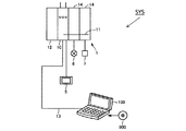
- FIG. 2 is a schematic diagram showing a PLC system SYS according to an embodiment of the present invention.
- the PLC system SYS according to the present embodiment includes a PLC 1 that is communicably connected to each other via EtherCAT (registered trademark), and a controller support device 100 as an information processing device.
- EtherCAT registered trademark
- Each PLC 1 typically has a CPU unit 10 as a main body for executing a program, a power supply unit 12 for supplying power to the CPU unit 10 and the like, and an IO (Input / Output) unit 14 for exchanging signals from the field. Including.
- the IO unit 14 is connected to the CPU unit 10 via the system bus 11.
- the IO unit 14 acquires an input signal from the detection sensor 6 that is a field device, and drives the relay 7 that is a field device according to the execution result of the program in the CPU unit 10.
- the display 5 includes an operation unit such as a touch panel, a display unit such as a liquid crystal display, a communication unit that communicates with the CPU unit 10, and a control unit that controls each unit.
- the PLC 1 can change various settings in accordance with the operation of the operation unit of the display 5, and can display predetermined information of the PLC 1 on the display 5.
- the controller support device 100 has a function of generating a program executed by the PLC 1 and a setting information, and a function of monitoring an operation state of the connected PLC 1 and various data values. Furthermore, the controller support apparatus 100 may have a debugging function and a simulation function in order to support the generation of an executable program by the user. As an example, the support device 100 is connected to the CPU unit 10 of the PLC 1 by a connection cable 13. The controller support device 100 is typically realized by a personal computer.
- the controller support device 100 is connected to the PLC 1 via a general-purpose interface such as Ethernet (registered trademark) or USB.
- the controller support device 100 When the controller support device 100 receives a command such as “online connection”, the controller support device 100 transmits / receives a command to / from the connected PLC 1, and corrects the user program stored in the PLC 1 memory or downloads or uploads a variable. Transition to a possible online state.
- a command such as “online connection”
- the controller support device 100 transmits / receives a command to / from the connected PLC 1, and corrects the user program stored in the PLC 1 memory or downloads or uploads a variable. Transition to a possible online state.
- the controller support device 100 may have a function of displaying to the user in different states in the offline state and the online state.
- PLC1 controls the controlled object by executing a user program.
- the PLC 1 When the PLC 1 is in an online state with the controller support device 100, when the PLC 1 receives a command related to acquisition of a variable value from the controller support device 100, the PLC support device 100 transmits the value of the variable stored in the memory via the communication interface. Forward to.
- the controller support device 100 receives the value of the variable transferred from the PLC 1 via the communication interface and stores it in the memory.
- the controller support apparatus 100 implements a variable monitoring function by periodically transmitting a command and acquiring the current value of the variable of the PLC 1.
- FIG. 4 is a diagram for explaining a user interface for registering variables to be monitored.
- the user interface hereinafter also referred to as a watch window
- the user interface for monitoring variables in the controller support device 100 is “Name”, “Online value”, “Modify”, “Comment”, “Data type”, “AT”, “Display” format. ". In the “Name” item, a variable to be monitored is registered.
- variable to be monitored is registered by inputting the variable name via an external input such as a keyboard and performing a confirmation operation.
- the controller support device 100 reads the current value of the variable from the memory and displays it in the item “Online value”.
- the allocation destination is displayed in the “AT” item.
- Data type displays the variable type.
- Display format a display format of a value to be displayed such as a current value and a changed value name is displayed.
- the watch window has a function to rewrite PLC1 variables.
- “Modify” item input the value of a variable to be modified by receiving external input such as a keyboard.
- the controller support device 100 transmits a command for rewriting the value of the variable calculated by the PLC 1 to the input value.
- the PLC 1 receives the command from the controller support device 100, it rewrites the value of the variable on the memory.
- the controller support device 100 transmits a command for reading the current value of the variable to the PLC 1.
- the PLC 1 receives a command for reading the current value
- the PLC 1 transmits the value of the variable stored in the memory to the controller support device 100.
- the controller support device 100 stores it in the memory and displays it in the item “Online value” in the watch window.
- the watch window displays “Name”, “Index”, “Modify”, “Comment”, “Data” type ”,“ AT ”,“ Display ”format items and values of structure type variables“ Online value ”(Table) ".
- ⁇ Variable of structure array type is registered in “Name” item.
- the watch window receives an input from an external input device such as a keyboard and inputs a structure array variable.
- an external input device such as a keyboard
- the structure type variable is registered.
- the watch window When a structure type variable is registered, the watch window reads the value of the variable in the memory and displays it in “Online value (Table)”. “Index” displays the member name of the structure array type variable specified in the console on “Online value (Table)”. “Comment” displays information registered in association with the variable specified in the console.
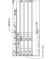
- FIG. 3 shows an example in which the current value is displayed for the variable “gStr” of the structure array type.
- “Online value (Table)” the structure member name and variable type in “gStr” are displayed.
- the variable of the member is displayed vertically with the name “param5” on the horizontal axis.
- the controller support device 100 transmits a command for rewriting the value of the variable calculated by the PLC 1 to the input value.
- the PLC 1 receives the command from the controller support device 100, it rewrites the value of the variable on the memory.
- the controller support device 100 transmits a command for reading the current value of the variable to the PLC 1.
- the PLC 1 receives a command for reading the current value
- the PLC 1 transmits the value of the variable stored in the memory to the controller support device 100.
- the controller support device 100 stores it in the memory and displays it in the item “Online value” in the watch window.
- the user can easily confirm whether or not the input value has been reflected.
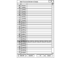
- FIG. 4 shows a user interface for selecting members on the structure array side to be displayed.
- a member name included in the structure array type variable is displayed as a selectable interface.
- check boxes such as “param1”, “param2”, “param3”, “param4”, “param5”... are displayed in the structure array type member.
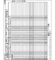
- FIG. 5 shows an example in which the member selected in FIG. 4 is displayed.
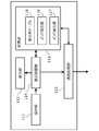
- FIG. 6 is a diagram illustrating a functional configuration in the controller support device 100.
- the controller support apparatus 100 includes an “operation unit 111”, a “display unit 112”, a “communication processing unit 113”, a “display control unit 114”, and a “storage unit 115”.
- the operation unit 111 is a user interface for receiving an operation from the user.
- the operation unit 111 corresponds to input means such as a keyboard and a mouse.
- the operation accepted by the operation unit 111 is accepted by the display control unit 114 as a command from the user.
- the display unit 112 is an interface for displaying various information. Corresponds to the display.
- the communication processing unit 113 is an interface for communicating with the PLC 1.
- the storage unit 115 is a memory for storing information.
- the storage unit 115 stores a member current value 116 that stores the current value of the variable received through the communication interface in association with the member, and a member that stores the write value input through the operation unit 111 in association with the member.
- a write value 117 and a display column table 118 that is information for the display control unit 114 to control display are stored.
- the display control unit 114 is a user interface program that controls display on the display unit 112.
- the display control unit 114 When the display control unit 114 receives an instruction that causes the controller support device 100 and the PLC 1 to be in an online state, the display control unit 114 transmits / receives a command to / from the PLC 1, corrects a user program stored in the PLC 1 memory, and changes variables. The state where the online state transition that can be downloaded or uploaded is made is notified via the display unit 112.
- the display control unit 114 When the display control unit 114 receives an input from the operation unit 111 and registers a variable to be monitored, the display control unit 114 reads the state of the corresponding variable from the storage unit 115 and based on information specified in the display column table 118. To display the current value of the variable.
- the structure member names and array elements are displayed in a matrix format.
- the display control unit 114 When the display control unit 114 receives an input from the operation unit 111 and receives a command for writing a variable, the display control unit 114 receives the value received via the communication processing unit 113 in the memory of the PLC 1 via the communication processing unit 113. The write operation is executed.
- the controller support device 100 communicates with the PLC 1 and transitions to an online state.
- the controller support apparatus 100 accepts registration of a variable name to be monitored.
- control to perform the acquired value is performed.
- the registered target is a structure array type variable
- control is performed so that array elements of member names are displayed in a matrix.
- FIG. 8 is a schematic diagram illustrating a hardware configuration of the controller support device 100 according to the embodiment of the present invention.
- controller support device 100 is typically composed of a general-purpose computer. From the viewpoint of maintainability, a notebook personal computer with excellent portability is preferable.
- the controller support apparatus 100 stores a CPU 101 that executes various programs including an operating system (OS), a ROM (Read Only Memory) 102 that stores BIOS and various data, and data necessary for executing the program by the CPU 101.
- a memory RAM 103 that provides a work area for storing data
- a hard disk (HDD) 104 that stores programs executed by the CPU 101 in a nonvolatile manner.
- the controller support device 100 further includes a keyboard 105 and a mouse 106 that accept operations from the user, and a display 107 for presenting information to the user.
- the controller support device 100 includes a communication interface (IF) 109 for communicating with the PLC 1 (CPU unit 10) and the like.
- IF communication interface
- various programs executed by the controller support device 100 are stored in the DVD-ROM 900 and distributed.
- the program stored in the DVD-ROM 900 is read by the DVD-ROM drive device 108 and stored in the hard disk (HDD) 104 or the like.
- the program may be downloaded from a host computer or the like via a network.
- PLC 5 Display 6: Detection sensor 7: Relay 10: CPU unit 11: System bus 12: Power supply unit 13: Connection cable 14: IO unit 100: Controller support device 101: CPU 102: ROM 103: RAM 104: HDD 105: Keyboard 106: Mouse 107: Display 108: DVD-ROM drive 109: Communication IF 111: Operation unit 112: Display unit 113: Communication processing unit 114: Display control unit 115: Storage unit 116: Member current value 117: Member write value 118: Display column table SYS: PLC system
Landscapes
- Engineering & Computer Science (AREA)
- Theoretical Computer Science (AREA)
- Physics & Mathematics (AREA)
- General Physics & Mathematics (AREA)
- Quality & Reliability (AREA)
- General Engineering & Computer Science (AREA)
- Automation & Control Theory (AREA)
- Programmable Controllers (AREA)
- Debugging And Monitoring (AREA)
Abstract
多数の変数で構成される、構造体変数のモニタを行う際に構造体のモニタをしやすいモニタ装置を提供する。モニタ装置は、通信部を介して制御装置の変数の値を取得し、ディスプレイ上に表示する。表示対象の変数が構造体型の変数であった場合には、構造体のメンバと配列要素の行または列にそれぞれ配置した行列の形式で表示を行う表示制御部を有する。
Description
本発明は、機械や設備の制御に用いられる制御装置のモニタリング装置に関する。
制御装置において制御プログラムに用いられる、変数のモニタを行う技術が知られている(例えば、特開2002-312197号公報)。特開2002-312197号公報では、プログラミング装置においてソースプログラムがなくとも制御プログラムに用いられる変数のモニタを行う技術が開示されている。
製造現場においては、当該モニタ機能は、制御装置が制御する機械の動作を当該変数の現在値を確認しながら、その値を変更し機械が正常に動作するかどうかを確認するためのデバッグのシーンや、機械が異常動作をした際には、当該モニタ装置を介して当該変数の値を確認及び修正を行い機械が正常に動作するように異常状態の解析に用いられる。
制御プログラムにおいて構造体を用いる場合がある。構造体は異なる型のデータを一括して扱うことができ、プログラミングの利便性を向上させるため制御装置を動作させるプログラムにおいてしばしば用いられる。
上述したようなシーンで構造体型の変数のモニタを行う場合、数多くの変数が存在する場合は、モニタを行う場合には表示される領域が画面上に収まり切らない場合があり、比較表示を行うことに関してユーザに不便を強いていた。
モニタリング装置は、制御装置とデータの送受信が可能なように接続され、制御装置の変数の値を取得し、表示可能に構成される。記モニタリング装置は、記制御装置との間で通信を行い、制御装置の変数の値を周期的に取得する通信部と、記制御装置で用いられる変数についてのデータ型、要素名を含む変数の定義情報を記憶する記憶部と、取得された変数の値を、ディスプレイ上で定義情報で定義された情報と対応づけて表示する表示制御部と、を備える。表示制御部は、表示対象の変数が構造体型の変数である場合に、構造体型の変数における要素名を行及び列に展開した表形式に並べ、取得した変数の値を前記要素に対応するように表示するよう制御する。
好ましくは、モニタリング装置は、表示対象の要素について指定をさせる入力部をさらに備える。表示制御部は、入力部から表示対象の前記要素についての指定を受け付けると、指定された、要素についてのみ表示するように制御する。
好ましくは、モニタリング装置は、書き換え対象の変数を指定及び書き換える変数の値を入力する入力部をさらに備える。表示制御部は、入力部から変数の要素または変数の値につき書き換えの入力を受け付けると、入力された変数の値と、変数の現在値とを比較可能な容態でディスプレイ上に表示する。通信部は、入力部から入力された変数の値を通信部を介して制御装置に送信する。
上記の発明によれば,制御プログラムに用いられる構造体のモニタをマトリックス形式で表示することで、変数の値を比較検討しながら変数の値の修正を行うことが可能となる。
<A.システム全体構成>
まず、コントローラサポート装置によって使用および運用を支援されるPLCを含むシステムについて説明する。
まず、コントローラサポート装置によって使用および運用を支援されるPLCを含むシステムについて説明する。
図は、本発明の実施の形態に係るPLCシステムSYSを示す模式図である。本実施の形態に係るPLCシステムSYSは、EtherCAT(登録商標)を介して互いに通信可能に接続されたPLC1と、情報処理装置としてのコントローラサポート装置100を含む。
各PLC1は、典型的には、プログラムを実行する主体であるCPUユニット10と、CPUユニット10などへ電力を供給する電源ユニット12と、フィールドからの信号を遣り取りするIO(Input/Output)ユニット14とを含む。IOユニット14は、CPUユニット10とシステムバス11を介して接続されている。典型的には、IOユニット14は、フィールド機器である検出センサ6から入力信号を取得し、またCPUユニット10でのプログラムの実行結果に応じてフィールド機器であるリレー7を駆動する。
表示器5は、タッチパネルなどの操作部と液晶ディスプレイなどの表示部とCPUユニット10と通信する通信部と各部を制御する制御部とを備える。PLC1は、表示器5の操作部による操作に応じて各種の設定の変更が可能であり、PLC1の所定の情報を表示器5に表示させることが可能である。
コントローラサポート装置100は、PLC1で実行されるプログラムおよび設定情報を生成する機能とともに、接続先のPLC1の運転状態や各種データの値などをモニタする機能を有している。さらに、コントローラサポート装置100は、ユーザによる実行可能プログラムの生成を支援するため、デバック機能やシミュレーション機能を有していてもよい。サポート装置100は、一例として、接続ケーブル13によって、PLC1のCPUユニット10に接続される。なお、コントローラサポート装置100は、典型的には、パーソナルコンピュータで実現される。
以下では、コントローラサポート装置を用いて、PLCシステムSYSの動作状態をモニタする機能に関して説明をする。
<B.処理の概要>
コントローラサポート装置100は、例えばイーサネット(登録商標)やUSB等汎用のインターフェースを介してPLC1に接続される。
コントローラサポート装置100は、例えばイーサネット(登録商標)やUSB等汎用のインターフェースを介してPLC1に接続される。
コントローラサポート装置100は、“オンライン接続”等の指令を受け付けると、接続されているPLC1とのコマンドの送受信を行い、PLC1のメモリに格納されているユーザプログラムの修正や変数のダウンロード乃至はアップロードか可能なオンライン状態に遷移する。
コントローラサポート装置100は、オフライン状態とオンライン状態では異なる容態でユーザに表示する等の機能を備えていても良い。
PLC1は、ユーザプログラムを実行することで制御対象を制御する。PLC1は、コントローラサポート装置100とオンライン状態となっている場合、コントローラサポート装置100から変数値の取得に関するコマンドを受信すると、メモリに格納されている変数の値を通信インターフェースを介してコントローラサポート装置100に転送する。
コントローラサポート装置100は、通信インターフェースを介してPLC1から転送された変数の値を受信し、メモリに格納する。コントローラサポート装置100は、定期的にコマンドを送信し、PLC1の変数の現在値を取得することにより、変数のモニタ機能を実現する。
図2を参照して、コントローラサポート装置100における変数のモニタ機能について説明する。コントローラサポート装置100は、モニタを行う対象の変数の登録を受け付ける。図はモニタを行う変数を登録するユーザインターフェースを説明する図である。コントローラサポート装置100における変数のモニタを行うユーザインターフェース(以後ウォッチウインドウとも称する)は、“Name”,“Online value”, “Modify”, “Comment”, “Data type”, “AT”, “Display format”から構成される。“Name”の項目には、モニタを行う変数が登録される。
モニタを行う変数はキーボード等の外部の入力を介して変数名を入力し、確定操作を行うことで登録がなされる。
コントローラサポート装置100は、モニタを行う変数が登録されるとメモリから当該変数における現在値を読出し、“Online value”の項目に表示する。
“AT”の項目には、割り付け先が表示される。“Data type”には変数の型が表示される。“Display format”には現在値、変更値名等の表示する値の表示形式が表示される。
ウォッチウインドウは、PLC1の変数を書き換える機能を有する。“Modify”の項目には、キーボード等の外部の入力を受け付けて修正したい変数の値を入力する。変数が入力されると、コントローラサポート装置100は、PLC1が演算する変数の値を入力された値に書き換えるコマンドを送信する。PLC1はコントローラサポート装置100から当該コマンドを受信すると、メモリ上の変数の値の書き換えを実行する。
コントローラサポート装置100は変数の現在値を読み出すコマンドをPLC1に対して送信する。PLC1は現在値を読み出すコマンドを受信すると、メモリに格納されている変数の値をコントローラサポート装置100に対して送信する。コントローラサポート装置100は変数の値を受信するとメモリに格納するとともに、ウォッチウインドウにおける“Online value”の項目に表示する。
図3を参照して、構造体型の変数のモニタ機能を説明する。ウォッチウインドウは“Name”、“Index”、“Modify”、“Comment”、”Data type”、“AT”、“Display format”の項目及び構造体型の変数の値を表示する“Online value(Table)”から構成される。
“Name”の項目に構造体配列型の変数が登録される。ウォッチウインドウは、キーボード等の外部入力機器からの入力を受け付けて構造体配列の変数が入力され、確定の入力がなされると構造体型の変数が登録される。
構造体型の変数が登録されると、ウォッチウインドウはメモリ上の変数の値を読出し“Online value(Table)”に表示をする。“Index”は“Online value(Table)”上のコンソールで指定されている構造体配列型の変数のメンバ名を表示する。“Comment”はコンソールで指定されている変数に関連づけられて登録されている情報を表示する。
図3では、構造体配列型の変数“gStr”について、現在値を表示している例を示している。“Online value(Table)”においては、“gStr”における構造体のメンバ名を及び変数の型を表示している。BOOL型の変数、メンバ名“param1”、INT型の変数、メンバ名“param2”、STRING型の変数、メンバ名“param3”、WORD型の変数、メンバ名“param4”、REAL型の変数、メンバ名“param5”を横軸として、当該メンバの変数を縦に表示している。
このように構造体配列型の変数について表示させるように制御しているため、多数の変数が存在する場合であっても、比較を行いながらモニタを行うことができる。
“Modify”の項目には、キーボード等の外部の入力を受け付けて修正したい変数の値を入力する。変数が入力されると、コントローラサポート装置100は、PLC1が演算する変数の値を入力された値に書き換えるコマンドを送信する。PLC1はコントローラサポート装置100から当該コマンドを受信すると、メモリ上の変数の値の書き換えを実行する。
コントローラサポート装置100は変数の現在値を読み出すコマンドをPLC1に対して送信する。PLC1は現在値を読み出すコマンドを受信すると、メモリに格納されている変数の値をコントローラサポート装置100に対して送信する。コントローラサポート装置100は変数の値を受信するとメモリに格納するとともに、ウォッチウインドウにおける“Online value”の項目に表示する。
このように、変数に書き込む値と変数の現在値を分けて表示していることにより、ユーザは入力をした値が反映がなされたか否かを容易に確認することができる。
次に図4を参照して、ウォッチウインドウの“Online value(Table)”で表示される構造体配列型の変数名を選択する例について説明をする。
図4は、表示をさせる構造体配列側のメンバを選択するユーザインターフェースを示す。構造体配列型の変数について、当該構造体配列型の変数に含まれるメンバ名を選択可能なインターフェースとして表示する。図では、構造体配列型メンバに“param1”、“param2”、“param3”、“param4”、“param5”・・・とチェックボックスが表示される。外部の入力機器から選択入力を受け付けて、確定操作の入力がなされると、ウォッチウインドウの“Online value(Table)”上では、選択されたメンバ名の変数のみが表示される。
図5では、図4で選択されたメンバが表示される例を示す。
このように構成することにより、ユーザが“Online value(Table)”上で表示される変数を選択することができ、多数の変数が含まれる場合であっても一覧としてモニタを行うとが可能となる。
<C.機能的構成>
図6はコントローラサポート装置100における機能構成を説明する図である。コントローラサポート装置100は、“操作部111”と“表示部112”と“通信処理部113”と“表示制御部114”と“記憶部115”とを備える。
図6はコントローラサポート装置100における機能構成を説明する図である。コントローラサポート装置100は、“操作部111”と“表示部112”と“通信処理部113”と“表示制御部114”と“記憶部115”とを備える。
操作部111は、ユーザからの操作を受け付けるためのユーザインターフェースである。操作部111はキーボード、マウス等の入力手段に対応する。操作部111が受け付けた操作は、表示制御部114において、ユーザからの命令として受けつけられる。
表示部112は、各種の情報表示するためのインターフェースである。ディスプレイに対応する。通信処理部113はPLC1と通信を行うためのインターフェースである。記憶部115は情報を記憶するためのメモリである。
記憶部115は、通信インターフェースを介して受信した変数の現在値をメンバと対応づけて記憶するするメンバ現在値116、操作部111を介して入力された書き込み値をメンバと対応づけて記憶するメンバ書込値117、表示制御部114が表示を制御するための情報である表示列テーブル118を記憶する。
表示制御部114は、表示部112における表示を制御するユーザインターフェースのプログラムである。
表示制御部114は、コントローラサポート装置100とPLC1がオンライン状態となるような命令を受け付けると、PLC1との間でコマンドの送受信を行い、PLC1のメモリに格納されているユーザプログラムの修正や変数のダウンロード乃至はアップロードか可能なオンライン状態遷移した状態を表示部112を介して通知する。
表示制御部114は、操作部111からの入力を受け付けてモニタ対象の変数が登録されると、記憶部115から該当する変数の状態を読出すとともに、表示列テーブル118で指定された情報に基づき、変数の現在値を表示させる。構造体配列型の変数が表示対象として登録された場合は、構造体のメンバ名と配列要素をマトリックス形式で表示をさせる。
また、表示制御部114は操作部111からの入力を受け付けて、変数の書き込みの命令を受け付けると、通信処理部113を介して書き込みを受け付けた値について通信処理部113を介してPLC1のメモリに対して書き込む動作を実行する。
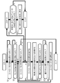
図7を参照して、モニタ機能に関するコントローラサポート装置100における制御の流れを説明する。
S1において、コントローラとの接続を受け付けるとコントローラサポート装置100は、PLC1との通信を行い、オンライン状態へ遷移する。
S2において、コントローラサポート装置100は、モニタ対象の変数名の登録を受け付ける。
S3において、コントローラとの切断の命令を受け付けると、オンライン状態からオフライン状態に遷移する。
S4において、S2において登録されたモニタ対象の変数名につき、メモリから変数名の現在値を取得する。
S5において、取得した値を行う制御を行う。登録された対象が構造体配列型の変数である場合については、メンバ名の配列要素をマトリックス状に表示するような制御を行う。
S6において、書き込みたいセルの値の選択を受付、S7において書き込みたい変数の値が入力されると、S7においてPLC1へ値を書き込む。
S11において、非表示・表示のパラメータの選択を受け付けると、S12において記憶部115に格納されている、表示列テーブル118の情報を書き換える。
<D.コントローラサポート装置のハードウェア構成>
図8は、本発明の実施の形態に係るコントローラサポート装置100のハードウェア構成を示す模式図である。図を参照して、コントローラサポート装置100は、典型的には、汎用のコンピュータで構成される。なお、メンテナンス性の観点からは、可搬性に優れたノート型のパーソナルコンピュータが好ましい。
図8は、本発明の実施の形態に係るコントローラサポート装置100のハードウェア構成を示す模式図である。図を参照して、コントローラサポート装置100は、典型的には、汎用のコンピュータで構成される。なお、メンテナンス性の観点からは、可搬性に優れたノート型のパーソナルコンピュータが好ましい。
コントローラサポート装置100は、オペレーティングシステム(OS)を含む各種プログラムを実行するCPU101と、BIOSや各種データを格納するROM(Read Only Memory)102と、CPU101でのプログラムの実行に必要なデータを格納するための作業領域を提供するメモリRAM103と、CPU101で実行されるプログラムなどを不揮発的に格納するハードディスク(HDD)104とを含む。
コントローラサポート装置100は、さらに、ユーザからの操作を受け付けるキーボード105およびマウス106と、情報をユーザに提示するためのディスプレイ107とを含む。コントローラサポート装置100は、PLC1(CPUユニット10)などと通信するための通信インターフェイス(IF)109を含む。
後述するように、コントローラサポート装置100で実行される各種プログラムは、DVD-ROM900に格納されて流通する。このDVD-ROM900に格納されたプログラムは、DVD-ROM駆動装置108によって読取られ、ハードディスク(HDD)104などへ格納される。あるいは、上位のホストコンピュータなどからネットワークを通じてプログラムをダウンロードするように構成してもよい。
1:PLC
5:表示器
6:検出センサ
7:リレー
10:CPUユニット
11:システムバス
12:電源ユニット
13:接続ケーブル
14:IOユニット
100:コントローラサポート装置
101:CPU
102:ROM
103:RAM
104:HDD
105:キーボード
106:マウス
107:ディスプレイ
108:DVD-ROM駆動装置
109:通信IF
111:操作部
112:表示部
113:通信処理部
114:表示制御部
115:記憶部
116:メンバ現在値
117:メンバ書込値
118:表示列テーブル
SYS:PLCシステム
5:表示器
6:検出センサ
7:リレー
10:CPUユニット
11:システムバス
12:電源ユニット
13:接続ケーブル
14:IOユニット
100:コントローラサポート装置
101:CPU
102:ROM
103:RAM
104:HDD
105:キーボード
106:マウス
107:ディスプレイ
108:DVD-ROM駆動装置
109:通信IF
111:操作部
112:表示部
113:通信処理部
114:表示制御部
115:記憶部
116:メンバ現在値
117:メンバ書込値
118:表示列テーブル
SYS:PLCシステム
Claims (3)
- 制御装置とデータの送受信が可能なように接続され、前記制御装置の変数の値を取得し、表示可能に構成されたモニタリング装置であって、
前記モニタリング装置は、
前記制御装置との間で通信を行い、前記制御装置の変数の値を周期的に取得する通信部と、
前記制御装置で用いられる前記変数についてのデータ型、要素名を含む変数の定義情報を記憶する記憶部と、
前記取得された変数の値を、ディスプレイ上で前記定義情報で定義された情報と対応づけて表示する表示制御部と、を備え、
前記表示制御部は、
前記表示対象の変数が構造体型の変数である場合に、前記構造体型の変数における要素名を行及び列に展開した表形式に並べ、前記取得した変数の値を前記要素に対応するように表示するよう制御する、
ことを特徴とするモニタリング装置。 - 前記モニタリング装置は、
前記表示対象の要素について指定をさせる入力部をさらに備え、
前記表示制御部は、前記入力部から表示対象の前記要素についての指定を受け付けると、前記指定された、前記要素についてのみ表示するように制御する、
請求項1に記載のモニタリング装置。 - 前記モニタリング装置は、
書き換え対象の変数を指定及び書き換える変数の値を入力する入力部をさらに備え、
前記表示制御部は、前記入力部から前記変数の要素または変数の値につき書き換えの入力を受け付けると、前記入力された変数の値と、前記変数の現在値とを比較可能な容態でディスプレイ上に表示し、
前記通信部は、前記入力部から入力された変数の値を通信部を介して制御装置に送信する、
請求項1に記載のモニタリング装置。
Applications Claiming Priority (2)
| Application Number | Priority Date | Filing Date | Title |
|---|---|---|---|
| JP2014138705A JP6213400B2 (ja) | 2014-07-04 | 2014-07-04 | モニタリング装置 |
| JP2014-138705 | 2014-07-04 |
Publications (1)
| Publication Number | Publication Date |
|---|---|
| WO2016002933A1 true WO2016002933A1 (ja) | 2016-01-07 |
Family
ID=55019459
Family Applications (1)
| Application Number | Title | Priority Date | Filing Date |
|---|---|---|---|
| PCT/JP2015/069277 Ceased WO2016002933A1 (ja) | 2014-07-04 | 2015-07-03 | モニタリング装置 |
Country Status (2)
| Country | Link |
|---|---|
| JP (1) | JP6213400B2 (ja) |
| WO (1) | WO2016002933A1 (ja) |
Citations (2)
| Publication number | Priority date | Publication date | Assignee | Title |
|---|---|---|---|---|
| JPH09114703A (ja) * | 1995-10-20 | 1997-05-02 | Hitachi Ltd | 分散処理システムの監視方法 |
| JP2000222252A (ja) * | 1999-02-03 | 2000-08-11 | Mitsubishi Electric Corp | メモリ内容表示方式及びメモリ内容編集方式 |
-
2014
- 2014-07-04 JP JP2014138705A patent/JP6213400B2/ja active Active
-
2015
- 2015-07-03 WO PCT/JP2015/069277 patent/WO2016002933A1/ja not_active Ceased
Patent Citations (2)
| Publication number | Priority date | Publication date | Assignee | Title |
|---|---|---|---|---|
| JPH09114703A (ja) * | 1995-10-20 | 1997-05-02 | Hitachi Ltd | 分散処理システムの監視方法 |
| JP2000222252A (ja) * | 1999-02-03 | 2000-08-11 | Mitsubishi Electric Corp | メモリ内容表示方式及びメモリ内容編集方式 |
Also Published As
| Publication number | Publication date |
|---|---|
| JP2016018250A (ja) | 2016-02-01 |
| JP6213400B2 (ja) | 2017-10-18 |
Similar Documents
| Publication | Publication Date | Title |
|---|---|---|
| JP4462449B2 (ja) | 制御システム設定装置 | |
| US10203681B2 (en) | Sequence-program-creation supporting apparatus | |
| JP6477319B2 (ja) | プラント制御システム | |
| JP2015176370A (ja) | 制御システム、方法、プログラムおよび情報処理装置 | |
| CN106030426B (zh) | 绘图装置以及控制系统 | |
| CN105103064A (zh) | 可编程控制器的周边装置以及调试辅助程序 | |
| WO2010017835A1 (en) | A system and a method for off-line programming of an industrial robot | |
| JP2013191129A (ja) | 情報処理装置、シミュレーション方法、およびプログラム | |
| WO2015170408A1 (ja) | 監視制御システム、監視端末及び監視プログラム | |
| KR102198204B1 (ko) | 시뮬레이션 장치 | |
| US9811071B2 (en) | System construction support apparatus | |
| JP5994862B2 (ja) | 開発支援装置及び開発支援プログラム | |
| US20140344428A1 (en) | System architecture support tool | |
| JP2005327263A (ja) | 制御システム設定装置 | |
| JP2010287034A (ja) | 外部機器とPLCとのModbusプロトコル通信アドレス表示方式 | |
| WO2019093170A1 (ja) | 制御プログラム開発支援装置、制御プログラム開発支援システム、制御プログラム開発支援方法、および、制御プログラム開発支援プログラム | |
| JP5000624B2 (ja) | 制御システムおよび携帯型プログラマブル表示器 | |
| JP5058246B2 (ja) | 機械モデルを組み込まれた制御装置 | |
| JP6213400B2 (ja) | モニタリング装置 | |
| US20230004146A1 (en) | Machining system, machine tool, information processing system, setting data inheritance method, and setting data inheritance program | |
| JP6337810B2 (ja) | 情報処理装置、情報処理方法、およびプログラム | |
| KR20200123224A (ko) | 작화 장치, 작화 프로그램 및 기억 매체 | |
| WO2019207679A1 (ja) | モニタ支援装置、プログラマブルロジックコントローラ、モニタ支援方法およびモニタ支援プログラム | |
| JP5398808B2 (ja) | 表示装置 | |
| JP4566904B2 (ja) | システム、制御プログラムおよびそのプログラムを記録した記録媒体、ならびに画像データ作成プログラムおよびそのプログラムを記録した記録媒体 |
Legal Events
| Date | Code | Title | Description |
|---|---|---|---|
| 121 | Ep: the epo has been informed by wipo that ep was designated in this application |
Ref document number: 15814402 Country of ref document: EP Kind code of ref document: A1 |
|
| NENP | Non-entry into the national phase |
Ref country code: DE |
|
| 122 | Ep: pct application non-entry in european phase |
Ref document number: 15814402 Country of ref document: EP Kind code of ref document: A1 |