WO2016002674A1 - ディスクブレーキ装置 - Google Patents
ディスクブレーキ装置 Download PDFInfo
- Publication number
- WO2016002674A1 WO2016002674A1 PCT/JP2015/068570 JP2015068570W WO2016002674A1 WO 2016002674 A1 WO2016002674 A1 WO 2016002674A1 JP 2015068570 W JP2015068570 W JP 2015068570W WO 2016002674 A1 WO2016002674 A1 WO 2016002674A1
- Authority
- WO
- WIPO (PCT)
- Prior art keywords
- rotor
- pad
- disc
- brake
- support
- Prior art date
- Legal status (The legal status is an assumption and is not a legal conclusion. Google has not performed a legal analysis and makes no representation as to the accuracy of the status listed.)
- Ceased
Links
Images

Classifications
-
- F—MECHANICAL ENGINEERING; LIGHTING; HEATING; WEAPONS; BLASTING
- F16—ENGINEERING ELEMENTS AND UNITS; GENERAL MEASURES FOR PRODUCING AND MAINTAINING EFFECTIVE FUNCTIONING OF MACHINES OR INSTALLATIONS; THERMAL INSULATION IN GENERAL
- F16D—COUPLINGS FOR TRANSMITTING ROTATION; CLUTCHES; BRAKES
- F16D55/00—Brakes with substantially-radial braking surfaces pressed together in axial direction, e.g. disc brakes
- F16D55/02—Brakes with substantially-radial braking surfaces pressed together in axial direction, e.g. disc brakes with axially-movable discs or pads pressed against axially-located rotating members
- F16D55/22—Brakes with substantially-radial braking surfaces pressed together in axial direction, e.g. disc brakes with axially-movable discs or pads pressed against axially-located rotating members by clamping an axially-located rotating disc between movable braking members, e.g. movable brake discs or brake pads
- F16D55/224—Brakes with substantially-radial braking surfaces pressed together in axial direction, e.g. disc brakes with axially-movable discs or pads pressed against axially-located rotating members by clamping an axially-located rotating disc between movable braking members, e.g. movable brake discs or brake pads with a common actuating member for the braking members
- F16D55/225—Brakes with substantially-radial braking surfaces pressed together in axial direction, e.g. disc brakes with axially-movable discs or pads pressed against axially-located rotating members by clamping an axially-located rotating disc between movable braking members, e.g. movable brake discs or brake pads with a common actuating member for the braking members the braking members being brake pads
-
- F—MECHANICAL ENGINEERING; LIGHTING; HEATING; WEAPONS; BLASTING
- F16—ENGINEERING ELEMENTS AND UNITS; GENERAL MEASURES FOR PRODUCING AND MAINTAINING EFFECTIVE FUNCTIONING OF MACHINES OR INSTALLATIONS; THERMAL INSULATION IN GENERAL
- F16D—COUPLINGS FOR TRANSMITTING ROTATION; CLUTCHES; BRAKES
- F16D65/00—Parts or details
- F16D65/02—Braking members; Mounting thereof
- F16D65/04—Bands, shoes or pads; Pivots or supporting members therefor
- F16D65/092—Bands, shoes or pads; Pivots or supporting members therefor for axially-engaging brakes, e.g. disc brakes
- F16D65/095—Pivots or supporting members therefor
- F16D65/097—Resilient means interposed between pads and supporting members or other brake parts
Definitions
- the present invention relates to a disc brake device, and in particular, a disc rotor that can rotate integrally with a wheel, a support that is assembled to a vehicle body, and a portion of the disc rotor that can be held between the disc rotor.
- a pair of brake pads assembled so as to be movable in the rotor axial direction, and the brake pads are urged in the rotor axial direction on the rotor turn-in side and rotor take-out side in the rotor circumferential direction of each brake pad.
- the present invention relates to a disc brake device that includes an urging member that presses, and a pushing member that pushes each of the brake pads toward the disc rotor during braking.
- This type of disc brake device is described in, for example, Patent Document 1 below, and is urged in a direction in which the rotor turn-in side and the rotor turn-out side of each brake pad are separated from the disc rotor by the urging member.
- a gap is formed between each brake pad and the disk rotor during non-braking.
- the present invention has been made to solve the above-described problems (correction of uneven wear of the brake pads and suppression of icing on the braked surface of the disk rotor).
- the urging member has a first urging portion that urges the rotor turn-in side of each brake pad in a direction to approach the disk rotor, and the rotor turn-out side of each brake pad from the disk rotor. It has the characteristic that it has the 2nd biasing part biased in the direction to separate.
- the urging member may be a pad support spring that is assembled to the support and holds the brake pads movably in the rotor axial direction.
- the urging member for urging the brake pad in the rotor axial direction on the rotor turn-in side and the rotor turn-out side in the rotor circumferential direction of each brake pad includes the brake pads of the brake pads.
- a first urging portion that urges the rotor inlet side in a direction away from the disk rotor, and a second urging member that urges the rotor outlet side of each brake pad in the direction of approaching the disk rotor; Has a part.
- the disc brake device of the present invention it is possible to bring the rotor delivery side portion of each brake pad into contact with the braked surface of the disc rotor during non-braking, and the rotor delivery side of each brake pad. It is possible to correct (reduce) uneven wear by wearing the part. Therefore, it is possible to suppress uneven wear of each brake pad.
- the second urging portion of the urging member urges each brake pad in the direction to bring the rotor delivery side close to the disc rotor. It is possible to bring the rotor delivery side of the pad into contact with the braked surface of the disk rotor. Therefore, even when icing occurs on the braked surface of the disk rotor when used in a cold region, the icing can be scraped off at the rotor delivery side portion of each brake pad. It is possible to suppress freezing in
- the pad support spring is configured.
- the pad support spring which is a constituent member.
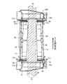
- FIG. 2 is a front view of a pad support spring disposed on a rotor turn-in side of an inner brake pad of the disc brake device shown in FIG. 1.
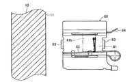
- FIG. 2 is a front view of a pad support spring disposed on a rotor delivery side of an outer brake pad of the disc brake device shown in FIG. 1.
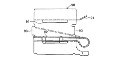
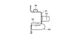
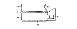
- It is a front view of the conventional pad support spring which does not make a brake pad approach or separate from a disk rotor.
- FIG. 1 to FIG. 3 show an embodiment in which the present invention is implemented in a movable caliper type disc brake device for a vehicle.
- the disc brake device 100 of this embodiment is assembled to an axle hub (rotating body not shown).
- a disc rotor 10 that can rotate integrally with a wheel (not shown), a support body (mounting) 20 that is assembled to a vehicle body (not shown), and a portion of the outer periphery of the disc rotor 10.
- the disc brake device 100 includes a pair of leaf springs (pad support springs) 50, 60, 70, and 80 that are assembled to the inner side and the outer side of the support body 20, respectively.
- the disk rotor 10 has an annular braked surface 11 that can be sandwiched between the lining 32 of the inner brake pad 30 and the lining 42 of the outer brake pad 40.
- the disk rotor 10 is braked for rotation when the braked surface 11 is sandwiched between the lining 32 of the inner brake pad 30 and the lining 42 of the outer brake pad 40 during braking.
- the support 20 is provided so as to straddle a part of the outer periphery of the disc rotor 10, and supports the inner side support portion 21 that supports the inner side brake pad 30 and the outer side brake pad 40.
- the outer side support part 22 is provided, and the inner side support part 21 is integrally provided with a mounting part (not shown) to the vehicle body.
- the movable caliper (not shown) is provided so as to straddle a part of the outer periphery of the disc rotor 10, and includes a cylinder portion on the inner side and a push arm portion on the outer side. And a connecting portion for connecting them.
- the movable caliper has a pair of support arm portions on the inner side, and is connected to the support body 20 in the rotor axial direction via a connecting pin extending in the rotor axial direction assembled to each support arm portion using a bolt. It is assembled to be movable.
- a piston (not shown) is assembled to a cylinder portion of a movable caliper through an annular seal member so as to be liquid-tight and slidable in the axial direction of the rotor. 10 is arranged so as to be capable of being pushed. Further, the piston is pushed by hydraulic oil supplied from a brake master cylinder (not shown) to an oil chamber formed between the piston and the disk rotor 10 during braking of the disk rotor 10, and the inner brake pad 30 is moved to the disk. It can be pressed toward the rotor 10 in the rotor axial direction.
- the movable caliper moves toward the inner side in the rotor axial direction due to the reaction force.
- the pushing arm portion of the caliper pushes and presses the outer brake pad 40 toward the braked surface 11 of the disc rotor 10 in the rotor axial direction.
- the inner brake pad 30 includes a back plate 31 and a lining 32 fixed to the back plate 31. Further, the inner brake pad 30 is disposed between the disc rotor 10 and the piston, and is supported by the projecting portions 31a and 31b formed at the rotor circumferential end of the back plate 31 via the leaf springs 50 and 60.
- the inner support portions 21 of the 20 are assembled to the concave support portions 21a and 21b so as to be movable in the rotor axial direction.
- the outer brake pad 40 includes a back plate 41 and a lining 42 fixed to the back plate 41. Further, the outer brake pad 40 is disposed between the disk rotor 10 and the pushing arm portion of the movable caliper, and the leaf springs 70, 41 b are formed by the convex portions 41 a and 41 b formed at the rotor circumferential end of the back plate 41. Through 80, it is assembled
- the leaf springs 50 and 70 are respectively assembled to the inner side support portion 21 and the concave support portions 21 a and 22 a on the rotor turn-in side of the outer side support portion 22 in the support body 20. As shown in FIG. 2 with the attached leaf spring 50 as an example, it has a U-shaped part 51, a tongue-like pad holding part 52, a pair of support holding parts 53, and a pad guiding part 54. .
- Each of the leaf springs 50 and 70 is made of a spring steel plate having a predetermined plate thickness. After being punched out from the spring steel plate into a predetermined shape, the leaf springs 50 and 70 are manufactured in a symmetrical shape by being bent into a formed shape. ing.
- the U-shaped portion 51 accommodates the rotor turn-in side convex portion 31a of the back plate 31 so as to be movable in the rotor axial direction.
- the tongue-like pad holding portion 52 urges the rotor turn-in side convex portion 31a of the back plate 31 outwardly of the rotor diameter, and the rotor turn-in side convex portion 31a of the back plate 31 (rotor turn-in of the brake pad 30). 2 (side portion) is urged in the direction of separating from the braked surface 11 of the disk rotor 10 (first urging portion), and as it is separated from the disk rotor 10 in the assembled state (state of FIG. 2). Inclined to descend.
- the support holding portion 53 elastically holds the concave support portion 21a in the rotor axial direction, and the leaf spring 50 is prevented from falling off from the concave support portion 21a.
- the pad guiding portion 54 guides the back plate 31 when the back plate 31 of the brake pad 30 is assembled into the pad support spring 50, and the assembling property of the brake pad 30 is good.
- the configuration of the leaf spring 50 other than the tongue-like pad holding portion 52 is the conventional pad support spring 90 illustrated in FIGS.
- the configuration other than the tongue-shaped pad holding portion 92 (the U-shaped portion 91, the support holding portion 93, the pad guiding portion 94, etc.) is the same.
- the tongue-like pad holding portion 92 urges the rotor turn-in side convex portion 31a of the back plate 31 outwardly of the rotor diameter, but does not urge the rotor turn-in side convex portion 31a of the back plate 31 in the rotor axial direction. In the assembled state shown in the figure, it is substantially horizontal and not inclined.
- the plate springs 60 and 80 are respectively assembled to the inner side support portion 21 and the concave support portions 21b and 22b on the rotor delivery side of the outer side support portion 22 in the support body 20, and are assembled to the outer side support portion 22.
- the leaf spring 80 As shown in FIG. 3 with the attached leaf spring 80 as an example, it has a U-shaped part 81, a tongue-like pad holding part 82, a pair of support holding parts 83, and a pad guiding part 84.
- Each of the leaf springs 60 and 80 is made of a spring steel plate having a predetermined plate thickness, and after being punched into a predetermined shape from the spring steel plate, the leaf springs 60 and 80 are manufactured in a symmetrical shape by being bent into a formed shape. ing.
- the U-shaped portion 81 accommodates the rotor delivery side convex portion 41b of the back plate 41 so as to be movable in the rotor axial direction.
- the tongue-shaped pad holding portion 82 urges the rotor outlet side convex portion 41b of the back plate 41 outwardly of the rotor diameter, and the rotor outlet side convex portion 41b of the back plate 41 (rotor extension of the brake pad 40).
- the second portion is urged in the direction in which the side portion is brought closer to the braked surface 11 of the disc rotor 10 (second urging portion) and is separated from the disc rotor 10 in the assembled state (the state shown in FIG. 3). Inclined to rise.
- the support holding portion 83 elastically holds the concave support portion 22b in the rotor axial direction, and the leaf spring 80 is prevented from falling off from the concave support portion 22b.
- the pad guiding portion 84 guides the back plate 41 when the back plate 41 of the brake pad 40 is assembled into the pad support spring 80, and the assembly of the brake pad 40 is good.
- the configuration of the leaf spring 80 other than the tongue-like pad holding portion 82 is the conventional pad support spring 90 illustrated in FIGS.
- the configuration other than the tongue-like pad holding portion 92 is the same.
- the brake pads 30 and 40 are attached in the rotor axial direction on the rotor turn-in side and the rotor turn-out side in the rotor circumferential direction of the brake pads 30 and 40, respectively.
- Plate springs (pad support springs) 50, 60, 70, 80 that urge the first urging portion (rotor retraction) that urges the rotor retraction side of each brake pad 30, 40 toward the disk rotor 10.
- each brake pad 30, 40 it is possible to bring the rotor delivery side portion of each brake pad 30, 40 into contact with the braked surface 11 of the disc rotor 10 during non-braking, It is possible to correct (reduce) the uneven wear by abrading the rotor delivery side portions of the brake pads 30 and 40. Therefore, uneven wear of each brake pad 30 and 40 can be suppressed.
- the second urging portion of the urging member urges the rotor delivery side of each brake pad 30 and 40 to approach the disc rotor 10, so that the rotor delivery side of each brake pad 30 and 40 contacts the braked surface 11 of the disc rotor 10. It is possible to make it. Therefore, even when icing occurs on the braked surface 11 of the disk rotor 10 when used in a cold region, the icing can be scraped off at the rotor delivery side portion of each brake pad 30, 40. It is possible to suppress icing on the braked surface 11 of the rotor 10.
- the pad support springs 50 and 70 disposed on the rotor retraction side of the brake pads 30 and 40.
- the tongue-like pad holding portion (52) of FIG. 2 has the shape illustrated in FIG. 2, and the tongue-like pad holding of each pad support spring 60, 80 disposed on the rotor delivery side of each brake pad 30, 40. Since the portion (82) can be implemented by taking the shape illustrated in FIG. 3, in a disc brake device having a pad support spring as a constituent member, the pad support spring as a constituent member can be effectively utilized to The invention can be implemented at low cost.
- the pad support springs 50 and 70 disposed on the rotor turn-in side of the brake pads 30 and 40 are provided with the tongue-like pad holding portions 52 (first urging portions) and the brakes
- first urging portions first urging portions
- the present invention was implemented by providing the tongue-like pad holding portion 82 (second urging portion) on each pad support spring 60, 80 disposed on the rotor delivery side of the pads 30, 40, each pad support spring was implemented.
- the present invention can be implemented in the same manner as in the above embodiment.
- the present invention provides a first biasing portion that biases the rotor return side of each brake pad in a direction of separating the rotor return side from the disk rotor to a pad return spring disposed on the rotor return side of each brake pad 30, 40. And a second urging portion that urges the pad return spring disposed on the rotor delivery side of each brake pad 30 and 40 in a direction to bring the rotor delivery side of each brake pad closer to the disk rotor. It is also possible to implement.
- the present invention is applied to a movable caliper type disc brake device for a vehicle.
- the present invention can be similarly applied to a fixed caliper type disc brake device for a vehicle.
Landscapes
- Engineering & Computer Science (AREA)
- General Engineering & Computer Science (AREA)
- Mechanical Engineering (AREA)
- Braking Arrangements (AREA)
Abstract
ディスクブレーキ装置(100)は、ディスクロータ(10)、支持体(20)、一対のブレーキパッド(30,40)、これら各ブレーキパッド(30,40)のロータ回入側とロータ回出側において同ブレーキパッド(30,40)をロータ軸方向に付勢する付勢部材(板バネ)(50,60,70,80)と、制動時に各ブレーキパッド(30,40)をディスクロータ(10)に向けて押動する押動部材とを備えている。各ブレーキパッド(30,40)のロータ回入側に配設される板バネ(50)には、各ブレーキパッドのロータ回入側をディスクロータ(10)から離間させる方向に付勢する第1付勢部が設けられ、各ブレーキパッド(30,40)のロータ回出側に配設される板バネ(80)には、各ブレーキパッドのロータ回出側をディスクロータ(10)に近接させる方向に付勢する第2付勢部が設けられている。
Description
本発明は、ディスクブレーキ装置に係り、特に、車輪と一体的に回転可能なディスクロータと、車体に組付けられる支持体と、前記ディスクロータの一部を挟持可能に配置されて前記支持体に対してロータ軸方向にて移動可能に組付けられる一対のブレーキパッドと、これら各ブレーキパッドのロータ周方向においけるロータ回入側とロータ回出側において同ブレーキパッドをロータ軸方向に付勢する付勢部材と、制動時に前記各ブレーキパッドを前記ディスクロータに向けて押動する押動部材とを備えているディスクブレーキ装置に関する。
この種のディスクブレーキ装置は、例えば、下記特許文献1に記載されていて、前記各ブレーキパッドのロータ回入側とロータ回出側が前記付勢部材によって前記ディスクロータから離間させる方向に付勢されていて、非制動時には、前記各ブレーキパッドと前記ディスクロータ間に隙間が形成されるように構成されている。
上記した特許文献1に記載されているディスクブレーキ装置においては、上記した構成(非制動時に、各ブレーキパッドをディスクロータから離間させる構成)によって非制動時のパッドの引き摺りを抑制することができる。しかし、ブレーキパッドの偏摩耗は、制動時においてブレーキパッドのロータ回入側がロータ回出側に比して多量に摩耗することに大きな要因があって、上記した構成では非制動時にブレーキパッドがロータから離間しているので偏摩耗を修正することができない。また、上記した構成では、寒冷地での使用に際して、ディスクロータの被制動面での氷結を誘発する。
本発明は、上記した課題を解決すべくなされたもの(ブレーキパッドの偏摩耗の修正と、ディスクロータの被制動面での氷結を抑制すること)であり、上記したディスクブレーキ装置において、
前記付勢部材が、前記各ブレーキパッドのロータ回入側を前記ディスクロータに近接させる方向に付勢する第1付勢部を有するとともに、前記各ブレーキパッドのロータ回出側を前記ディスクロータから離間させる方向に付勢する第2付勢部を有していることに特徴がある。
前記付勢部材が、前記各ブレーキパッドのロータ回入側を前記ディスクロータに近接させる方向に付勢する第1付勢部を有するとともに、前記各ブレーキパッドのロータ回出側を前記ディスクロータから離間させる方向に付勢する第2付勢部を有していることに特徴がある。
上記した本発明の実施に際して、前記付勢部材が、前記支持体に組付けられて前記各ブレーキパッドをロータ軸方向に移動可能に保持するパッドサポートスプリングであることも可能である。
上記した本発明のディスクブレーキ装置においては、各ブレーキパッドのロータ周方向におけるロータ回入側とロータ回出側において同ブレーキパッドをロータ軸方向に付勢する付勢部材が、前記各ブレーキパッドのロータ回入側を前記ディスクロータから離間させる方向に付勢する第1付勢部を有するとともに、前記各ブレーキパッドのロータ回出側を前記ディスクロータに近接させる方向に付勢する第2付勢部を有している。
このため、本発明のディスクブレーキ装置においては、非制動時において、各ブレーキパッドのロータ回出側部分をディスクロータの被制動面に接触させることが可能であり、各ブレーキパッドのロータ回出側部分を摩耗させて、偏摩耗を修正する(減少させる)ことが可能である。したがって、各ブレーキパッドの偏摩耗を抑制することが可能である。
また、本発明のディスクブレーキ装置においては、非制動時においても、付勢部材の第2付勢部が各ブレーキパッドのロータ回出側をディスクロータに近接させる方向に付勢するため、各ブレーキパッドのロータ回出側をディスクロータの被制動面に接触させることが可能である。したがって、寒冷地での使用に際して、ディスクロータの被制動面にて氷結が生じても、その氷結を各ブレーキパッドのロータ回出側部分にて削り取ることが可能であり、ディスクロータの被制動面での氷結を抑制することが可能である。
上記した本発明の実施に際して、前記付勢部材が、前記支持体に組付けられて前記各ブレーキパッドをロータ軸方向に移動可能に保持するパッドサポートスプリングである場合には、パッドサポートスプリングを構成部材とするディスクブレーキ装置において、構成部材であるパッドサポートスプリングを有効に活用して、本発明を安価に実施することが可能である。
以下に、本発明の一実施形態を図面に基づいて説明する。図1~図3本発明を車両用の可動キャリパ型ディスクブレーキ装置に実施した実施形態を示していて、この実施形態のディスクブレーキ装置100は、車軸ハブ(図示省略の回転体)に組付けられて車輪(図示省略)と一体的に回転可能なディスクロータ10と、車体(図示省略)に組付けられる支持体(マウンティング)20と、ディスクロータ10の外周部の一部分を跨ぐようにして配置されて支持体20に対してロータ軸方向に移動可能に組付けられる可動キャリパ(図示省略)と、この可動キャリパに組付けられるピストン(図示省略)、インナー側ブレーキパッド30、アウター側ブレーキパッド40を備えている。また、ディスクブレーキ装置100は、支持体20のインナー側とアウター側にそれぞれ組付けた一対の板バネ(パッドサポートスプリング)50・60,70・80を備えている。
ディスクロータ10は、インナー側ブレーキパッド30のライニング32とアウター側ブレーキパッド40のライニング42によって挟持可能な環状の被制動面11を有している。また、ディスクロータ10は、被制動面11が制動時にインナー側ブレーキパッド30のライニング32およびアウター側ブレーキパッド40のライニング42によって挟持されることにより、回転を制動されるようになっている。
支持体20は、周知のように、ディスクロータ10の一部の外周を跨ぐようにして設けられていて、インナー側ブレーキパッド30を支持するインナー側支持部21と、アウター側ブレーキパッド40を支持するアウター側支持部22を備えていて、インナー側支持部21には車体への取付部(図示省略)が一体的に設けられている。
可動キャリパ(図示省略)は、周知のように、ディスクロータ10の一部の外周を跨ぐようにして設けられていて、インナー側にシリンダ部を備え、アウター側に押動アーム部を備えていて、これらを連結する連結部をも備えている。また、可動キャリパは、インナー側に一対の支持アーム部を備えていて、各支持アーム部にボルトを用いて組付けたロータ軸方向に延びる連結ピンを介して、支持体20にロータ軸方向に移動可能に組付けられている。
ピストン(図示省略)は、可動キャリパのシリンダ部に周知のように環状のシール部材を介して液密的かつロータ軸方向に摺動可能に組付けられていて、インナー側ブレーキパッド30をディスクロータ10に向けて押動可能に配置されている。また、ピストンは、ディスクロータ10の制動時に、シリンダ部との間に形成される油室にブレーキマスタシリンダ(図示省略)から供給される作動油によって押動されて、インナー側ブレーキパッド30をディスクロータ10に向けてロータ軸方向に押圧可能である。なお、ピストンがインナー側ブレーキパッド30をディスクロータ10の被制動面11に向けてロータ軸方向に押動・押圧するときには、その反力によって可動キャリパがロータ軸方向インナー側に移動して、可動キャリパの押動アーム部がアウター側ブレーキパッド40をディスクロータ10の被制動面11に向けてロータ軸方向に押動・押圧する。
インナー側ブレーキパッド30は、裏板31と、この裏板31に固着したライニング32とを備えている。また、インナー側ブレーキパッド30は、ディスクロータ10とピストン間に配置されていて、裏板31のロータ周方向端部に形成した凸部31a、31bにて板バネ50,60を介して支持体20のインナー側支持部21に形成した凹状支持部21a、21bにロータ軸方向に移動可能に組付けられている。
アウター側ブレーキパッド40は、裏板41と、この裏板41に固着したライニング42とを備えている。また、アウター側ブレーキパッド40は、ディスクロータ10と可動キャリパの押動アーム部間に配置されていて、裏板41のロータ周方向端部に形成した凸部41a、41bにて板バネ70,80を介して支持体20のアウター側支持部22に形成した凹状支持部22a、22bにロータ軸方向に移動可能に組付けられている。
各板バネ50,70は、支持体20におけるインナー側支持部21およびアウター側支持部22のロータ回入側の凹状支持部21a、22aにそれぞれ組付けられていて、インナー側支持部21に組付けられた板バネ50を例として図2に示したように、コ字状部51と舌片状パッド保持部52と一対のサポート保持部53を有するとともに、パッド誘導部54を有している。なお、各板バネ50,70は、所定板厚のバネ鋼板を素材とするものであり、同バネ鋼板から所定の形状に打ち抜かれた後に、成形形状に折り曲げられることで左右対称形状に製作されている。
コ字状部51は、裏板31のロータ回入側凸部31aをロータ軸方向にて移動可能に収容している。舌片状パッド保持部52は、裏板31のロータ回入側凸部31aをロータ径外方に付勢するとともに、裏板31のロータ回入側凸部31a(ブレーキパッド30のロータ回入側部分)をディスクロータ10の被制動面11から離間させる方向に付勢するもの(第1付勢部)であり、組付状態(図2の状態)にてディスクロータ10から離間するにしたがって下降するように傾斜している。
サポート保持部53は、凹状支持部21aをロータ軸方向にて弾性的に挟持するものであり、板バネ50の凹状支持部21aからの脱落が防止されている。パッド誘導部54は、ブレーキパッド30の裏板31をパッドサポートスプリング50に組み込む際に裏板31を誘導するものであり、ブレーキパッド30の組付性が良好とされている。
なお、板バネ50における舌片状パッド保持部52以外の構成(コ字状部51、サポート保持部53、パッド誘導部54等)は、図4~図6に例示した従来のパッドサポートスプリング90における舌片状パッド保持部92以外の構成(コ字状部91、サポート保持部93、パッド誘導部94等)と同じである。舌片状パッド保持部92は、裏板31のロータ回入側凸部31aをロータ径外方に付勢するものの、裏板31のロータ回入側凸部31aをロータ軸方向に付勢しないように構成されていて、図に示した組付状態にて略水平であり傾斜していない。
各板バネ60,80は、支持体20におけるインナー側支持部21およびアウター側支持部22のロータ回出側の凹状支持部21b、22bにそれぞれ組付けられていて、アウター側支持部22に組付けられた板バネ80を例として図3に示したように、コ字状部81と舌片状パッド保持部82と一対のサポート保持部83を有するとともに、パッド誘導部84を有している。なお、各板バネ60,80は、所定板厚のバネ鋼板を素材とするものであり、同バネ鋼板から所定の形状に打ち抜かれた後に、成形形状に折り曲げられることで左右対称形状に製作されている。
コ字状部81は、裏板41のロータ回出側凸部41bをロータ軸方向にて移動可能に収容している。舌片状パッド保持部82は、裏板41のロータ回出側凸部41bをロータ径外方に付勢するとともに、裏板41のロータ回出側凸部41b(ブレーキパッド40のロータ回出側部分)をディスクロータ10の被制動面11に近接させる方向に付勢するもの(第2付勢部)であり、組付状態(図3の状態)にてディスクロータ10から離間するにしたがって上昇するように傾斜している。
サポート保持部83は、凹状支持部22bをロータ軸方向にて弾性的に挟持するものであり、板バネ80の凹状支持部22bからの脱落が防止されている。パッド誘導部84は、ブレーキパッド40の裏板41をパッドサポートスプリング80に組み込む際に裏板41を誘導するものであり、ブレーキパッド40の組付性が良好とされている。
なお、板バネ80における舌片状パッド保持部82以外の構成(コ字状部81、サポート保持部83、パッド誘導部84等)は、図4~図6に例示した従来のパッドサポートスプリング90における舌片状パッド保持部92以外の構成(コ字状部51、サポート保持部53、パッド誘導部54等)と同じである。
上記のように構成したこの実施形態のディスクブレーキ装置100においては、各ブレーキパッド30,40のロータ周方向におけるロータ回入側とロータ回出側において各ブレーキパッド30,40をロータ軸方向に付勢する板バネ(パッドサポートスプリング)50,60,70,80が、各ブレーキパッド30,40のロータ回入側をディスクロータ10に近接させる方向に付勢する第1付勢部(ロータ回入側に配設される例えば、板バネ50の舌片状パッド保持部52)を有するとともに、各ブレーキパッド30,40のロータ回出側をディスクロータ10から離間させる方向に付勢する第2付勢部(ロータ回出側に配設される例えば、板バネ80の舌片状パッド保持部82)を有している。
このため、この実施形態のディスクブレーキ装置100においては、非制動時において、各ブレーキパッド30,40のロータ回出側部分をディスクロータ10の被制動面11に接触させることが可能であり、各ブレーキパッド30,40のロータ回出側部分を摩耗させて、偏摩耗を修正する(減少させる)ことが可能である。したがって、各ブレーキパッド30,40の偏摩耗を抑制することが可能である。
また、この実施形態のディスクブレーキ装置100においては、非制動時においても、付勢部材の第2付勢部(ロータ回出側に配設される例えば、板バネ80の舌片状パッド保持部82)が各ブレーキパッド30,40のロータ回出側をディスクロータ10に近接させる方向に付勢するため、各ブレーキパッド30,40のロータ回出側をディスクロータ10の被制動面11に接触させることが可能である。したがって、寒冷地での使用に際して、ディスクロータ10の被制動面11にて氷結が生じても、その氷結を各ブレーキパッド30,40のロータ回出側部分にて削り取ることが可能であり、ディスクロータ10の被制動面11での氷結を抑制することが可能である。
また、この実施形態においては、パッドサポートスプリングをディスクブレーキ装置の構成部材とする当該ディスクブレーキ装置100において、各ブレーキパッド30,40のロータ回入側に配設される各パッドサポートスプリング50,70の舌片状パッド保持部(52)を図2に例示した形状とするとともに、各ブレーキパッド30,40のロータ回出側に配設される各パッドサポートスプリング60,80の舌片状パッド保持部(82)を図3に例示した形状とすることにより実施することができるため、パッドサポートスプリングを構成部材とするディスクブレーキ装置において、構成部材であるパッドサポートスプリングを有効に活用して、本発明を安価に実施することが可能である。
上記した実施形態では、各ブレーキパッド30,40のロータ回入側に配設される各パッドサポートスプリング50,70に舌片状パッド保持部52(第1付勢部)を設けるとともに、各ブレーキパッド30,40のロータ回出側に配設される各パッドサポートスプリング60,80に舌片状パッド保持部82(第2付勢部)を設けて本発明を実施したが、各パッドサポートスプリング50,70と各パッドサポートスプリング60,80がそれぞれ一体的に構成されているディスクブレーキ装置においても、上記実施形態と同様に本発明を実施することが可能である。
また、本発明は、各ブレーキパッド30,40のロータ回入側に配設されるパッド戻しバネに各ブレーキパッドのロータ回入側をディスクロータから離間させる方向に付勢する第1付勢部を設けるとともに、各ブレーキパッド30,40のロータ回出側に配設されるパッド戻しバネに各ブレーキパッドのロータ回出側をディスクロータに近接させる方向に付勢する第2付勢部を設けて実施することも可能である。
また、上記した実施形態においては、本発明を車両用の可動キャリパ型ディスクブレーキ装置に実施したが、本発明は車両用の固定キャリパ型ディスクブレーキ装置にも同様に実施することが可能である。
100…ディスクブレーキ装置、10…ディスクロータ、11…被制動面、20…支持体(マウンティング)、30…インナー側ブレーキパッド、31a…ロータ回入側凸部、31b…ロータ回出側凸部、40…アウター側ブレーキパッド、41a…ロータ回入側凸部、41b…ロータ回出側凸部、50,60,70,80…板バネ(パッドサポートスプリング)
Claims (2)
- 車輪と一体的に回転可能なディスクロータと、車体に組付けられる支持体と、前記ディスクロータの一部を挟持可能に配置されて前記支持体に対してロータ軸方向にて移動可能に組付けられる一対のブレーキパッドと、これら各ブレーキパッドのロータ周方向におけるロータ回入側とロータ回出側において同ブレーキパッドをロータ軸方向に付勢する付勢部材と、制動時に前記各ブレーキパッドを前記ディスクロータに向けて押動する押動部材とを備えているディスクブレーキ装置において、
前記付勢部材が、前記各ブレーキパッドのロータ回入側を前記ディスクロータから離間させる方向に付勢する第1付勢部を有するとともに、前記各ブレーキパッドのロータ回出側を前記ディスクロータに近接させる方向に付勢する第2付勢部を有していることを特徴とするディスクブレーキ装置。 - 請求項1に記載のディスクブレーキ装置において、
前記付勢部材が、前記支持体に組付けられて前記各ブレーキパッドをロータ軸方向に移動可能に保持するパッドサポートスプリングであることを特徴とするディスクブレーキ装置。
Applications Claiming Priority (2)
| Application Number | Priority Date | Filing Date | Title |
|---|---|---|---|
| JP2014-133992 | 2014-06-30 | ||
| JP2014133992A JP2016011718A (ja) | 2014-06-30 | 2014-06-30 | ディスクブレーキ装置 |
Publications (1)
| Publication Number | Publication Date |
|---|---|
| WO2016002674A1 true WO2016002674A1 (ja) | 2016-01-07 |
Family
ID=55019210
Family Applications (1)
| Application Number | Title | Priority Date | Filing Date |
|---|---|---|---|
| PCT/JP2015/068570 Ceased WO2016002674A1 (ja) | 2014-06-30 | 2015-06-26 | ディスクブレーキ装置 |
Country Status (2)
| Country | Link |
|---|---|
| JP (1) | JP2016011718A (ja) |
| WO (1) | WO2016002674A1 (ja) |
Citations (2)
| Publication number | Priority date | Publication date | Assignee | Title |
|---|---|---|---|---|
| JP2000161395A (ja) * | 1998-11-26 | 2000-06-13 | Akebono Brake Ind Co Ltd | ディスクブレーキ用パッドクリップ |
| JP2002276700A (ja) * | 2001-03-21 | 2002-09-25 | Aisin Seiki Co Ltd | ディスクブレーキ |
-
2014
- 2014-06-30 JP JP2014133992A patent/JP2016011718A/ja active Pending
-
2015
- 2015-06-26 WO PCT/JP2015/068570 patent/WO2016002674A1/ja not_active Ceased
Patent Citations (2)
| Publication number | Priority date | Publication date | Assignee | Title |
|---|---|---|---|---|
| JP2000161395A (ja) * | 1998-11-26 | 2000-06-13 | Akebono Brake Ind Co Ltd | ディスクブレーキ用パッドクリップ |
| JP2002276700A (ja) * | 2001-03-21 | 2002-09-25 | Aisin Seiki Co Ltd | ディスクブレーキ |
Also Published As
| Publication number | Publication date |
|---|---|
| JP2016011718A (ja) | 2016-01-21 |
Similar Documents
| Publication | Publication Date | Title |
|---|---|---|
| JP2015028376A5 (ja) | ||
| JP5368528B2 (ja) | 静止用機械式ディスクブレーキ | |
| CN103946580B (zh) | 盘式制动装置 | |
| US8839917B2 (en) | Disc brake apparatus | |
| JP2015031325A5 (ja) | ||
| US9822832B2 (en) | Disc brake device | |
| JPWO2019049539A1 (ja) | 車両用ディスクブレーキ | |
| JP5879032B2 (ja) | ディスクブレーキ | |
| WO2018007194A3 (de) | Scheibenbremse für ein nutzfahrzeug | |
| JP2016011718A (ja) | ディスクブレーキ装置 | |
| JP5112384B2 (ja) | 車両用ディスクブレーキ | |
| JP2011163520A (ja) | ディスクブレーキ装置 | |
| JP2017172731A (ja) | ブレーキ装置 | |
| JP6351190B2 (ja) | ディスクブレーキ | |
| JP6434795B2 (ja) | ディスクブレーキ用摩擦パッド組立て体 | |
| JP6134613B2 (ja) | ディスクブレーキ | |
| JP2012072848A (ja) | ディスクブレーキおよび摩擦パッド | |
| JP5988028B2 (ja) | ディスクブレーキ及びパッドサポート | |
| JP6921024B2 (ja) | ディスクブレーキ | |
| JP2016070321A (ja) | ディスクブレーキ装置 | |
| JP6688645B2 (ja) | ブレーキ装置 | |
| JP2012167739A (ja) | ディスクブレーキ | |
| JP4955095B2 (ja) | 車両用ディスクブレーキ | |
| JP2014190534A5 (ja) | ||
| JP6678056B2 (ja) | ディスクブレーキ |
Legal Events
| Date | Code | Title | Description |
|---|---|---|---|
| 121 | Ep: the epo has been informed by wipo that ep was designated in this application |
Ref document number: 15814762 Country of ref document: EP Kind code of ref document: A1 |
|
| NENP | Non-entry into the national phase |
Ref country code: DE |
|
| 122 | Ep: pct application non-entry in european phase |
Ref document number: 15814762 Country of ref document: EP Kind code of ref document: A1 |