WO2016002592A1 - 液化ガス気化装置および液化ガス気化システム - Google Patents
液化ガス気化装置および液化ガス気化システム Download PDFInfo
- Publication number
- WO2016002592A1 WO2016002592A1 PCT/JP2015/068108 JP2015068108W WO2016002592A1 WO 2016002592 A1 WO2016002592 A1 WO 2016002592A1 JP 2015068108 W JP2015068108 W JP 2015068108W WO 2016002592 A1 WO2016002592 A1 WO 2016002592A1
- Authority
- WO
- WIPO (PCT)
- Prior art keywords
- gas
- condensed water
- liquefied gas
- pipe
- storage tank
- Prior art date
- Legal status (The legal status is an assumption and is not a legal conclusion. Google has not performed a legal analysis and makes no representation as to the accuracy of the status listed.)
- Ceased
Links
Images







Classifications
-
- F—MECHANICAL ENGINEERING; LIGHTING; HEATING; WEAPONS; BLASTING
- F17—STORING OR DISTRIBUTING GASES OR LIQUIDS
- F17C—VESSELS FOR CONTAINING OR STORING COMPRESSED, LIQUEFIED OR SOLIDIFIED GASES; FIXED-CAPACITY GAS-HOLDERS; FILLING VESSELS WITH, OR DISCHARGING FROM VESSELS, COMPRESSED, LIQUEFIED, OR SOLIDIFIED GASES
- F17C9/00—Methods or apparatus for discharging liquefied or solidified gases from vessels not under pressure
- F17C9/02—Methods or apparatus for discharging liquefied or solidified gases from vessels not under pressure with change of state, e.g. vaporisation
-
- F—MECHANICAL ENGINEERING; LIGHTING; HEATING; WEAPONS; BLASTING
- F17—STORING OR DISTRIBUTING GASES OR LIQUIDS
- F17D—PIPE-LINE SYSTEMS; PIPE-LINES
- F17D1/00—Pipe-line systems
- F17D1/02—Pipe-line systems for gases or vapours
- F17D1/04—Pipe-line systems for gases or vapours for distribution of gas
-
- F—MECHANICAL ENGINEERING; LIGHTING; HEATING; WEAPONS; BLASTING
- F25—REFRIGERATION OR COOLING; COMBINED HEATING AND REFRIGERATION SYSTEMS; HEAT PUMP SYSTEMS; MANUFACTURE OR STORAGE OF ICE; LIQUEFACTION SOLIDIFICATION OF GASES
- F25B—REFRIGERATION MACHINES, PLANTS OR SYSTEMS; COMBINED HEATING AND REFRIGERATION SYSTEMS; HEAT PUMP SYSTEMS
- F25B39/00—Evaporators; Condensers
- F25B39/02—Evaporators
-
- F—MECHANICAL ENGINEERING; LIGHTING; HEATING; WEAPONS; BLASTING
- F28—HEAT EXCHANGE IN GENERAL
- F28D—HEAT-EXCHANGE APPARATUS, NOT PROVIDED FOR IN ANOTHER SUBCLASS, IN WHICH THE HEAT-EXCHANGE MEDIA DO NOT COME INTO DIRECT CONTACT
- F28D1/00—Heat-exchange apparatus having stationary conduit assemblies for one heat-exchange medium only, the media being in contact with different sides of the conduit wall, in which the other heat-exchange medium is a large body of fluid, e.g. domestic or motor car radiators
- F28D1/02—Heat-exchange apparatus having stationary conduit assemblies for one heat-exchange medium only, the media being in contact with different sides of the conduit wall, in which the other heat-exchange medium is a large body of fluid, e.g. domestic or motor car radiators with heat-exchange conduits immersed in the body of fluid
- F28D1/04—Heat-exchange apparatus having stationary conduit assemblies for one heat-exchange medium only, the media being in contact with different sides of the conduit wall, in which the other heat-exchange medium is a large body of fluid, e.g. domestic or motor car radiators with heat-exchange conduits immersed in the body of fluid with tubular conduits
- F28D1/053—Heat-exchange apparatus having stationary conduit assemblies for one heat-exchange medium only, the media being in contact with different sides of the conduit wall, in which the other heat-exchange medium is a large body of fluid, e.g. domestic or motor car radiators with heat-exchange conduits immersed in the body of fluid with tubular conduits the conduits being straight
-
- F—MECHANICAL ENGINEERING; LIGHTING; HEATING; WEAPONS; BLASTING
- F28—HEAT EXCHANGE IN GENERAL
- F28F—DETAILS OF HEAT-EXCHANGE AND HEAT-TRANSFER APPARATUS, OF GENERAL APPLICATION
- F28F1/00—Tubular elements; Assemblies of tubular elements
- F28F1/10—Tubular elements and assemblies thereof with means for increasing heat-transfer area, e.g. with fins, with projections, with recesses
- F28F1/12—Tubular elements and assemblies thereof with means for increasing heat-transfer area, e.g. with fins, with projections, with recesses the means being only outside the tubular element
- F28F1/24—Tubular elements and assemblies thereof with means for increasing heat-transfer area, e.g. with fins, with projections, with recesses the means being only outside the tubular element and extending transversely
- F28F1/32—Tubular elements and assemblies thereof with means for increasing heat-transfer area, e.g. with fins, with projections, with recesses the means being only outside the tubular element and extending transversely the means having portions engaging further tubular elements
Definitions
- the present invention relates to a liquefied gas vaporization apparatus and a liquefied gas vaporization system for vaporizing a liquefied gas by heat exchange with an intermediate medium.
- a liquefied gas vaporizer that vaporizes liquefied gas by heat exchange with an intermediate medium
- an intermediate medium for example, there is one described in Patent Document 1.
- the intermediate medium is circulated between the intermediate medium evaporation section and the liquefied gas vaporization section, and the intermediate medium vaporized in the intermediate medium evaporation section is condensed in the liquefied gas vaporization section, thereby reducing the temperature.
- the liquefied gas is vaporized to generate vaporized gas. According to this configuration, since the liquefied gas is vaporized using the condensation latent heat of the intermediate medium, the amount of circulation of the intermediate medium can be reduced according to the enthalpy ratio of latent heat / sensible heat. Yes.
- the above-mentioned liquefied gas vaporizer vaporizes the intermediate medium in the heat transfer tube by circulating the atmosphere around the heat transfer tube of the intermediate medium evaporation section. At this time, water vapor contained in the atmosphere is condensed on the surface of the heat transfer tube, and condensed water is generated. The condensed water generated in this way is generally discarded without being particularly used, and a method for effectively utilizing the condensed water has been demanded.
- the vaporized gas vaporized in the liquefied gas vaporization unit is generally heated to a predetermined target temperature by a heater, but additional power is required to operate the heater. Become. Therefore, there is a demand for reducing the power consumption in the liquefied gas vaporizer by reducing the load on the heater as much as possible and eliminating the heater in some cases.
- the present invention effectively uses the condensed water generated on the surface of the heat transfer tube through which the intermediate medium flows in the liquefied gas vaporization apparatus and the liquefied gas vaporization system using the intermediate medium, thereby reducing the power consumption.
- the purpose is to reduce it.
- a liquefied gas vaporizer includes an intermediate medium heater for heating an intermediate medium flowing in a heat transfer tube by heat exchange with a heating gas, and the intermediate medium heating A liquefied gas evaporator that vaporizes a liquefied gas to generate a vaporized gas by heat exchange with the intermediate medium that has been heated in a vessel; a gas pipe through which the vaporized gas generated by the liquefied gas evaporator flows;
- the heating gas contains water vapor, and the surface temperature of the heat transfer tube is lower than the dew point of the heating gas, so that condensed water is generated on the surface of the heat transfer tube,
- the condensed water is heated by heat exchange with the atmosphere in a state where it is stored in a storage part of a storage tank disposed at a position lower than the heat transfer pipe, and then to the gas pipe at a position lower than the storage tank.
- the condensed water generated on the surface of the heat transfer tube of the intermediate medium heater is heated by heat exchange with the atmosphere while being stored in the storage portion of the storage tank. And the vaporized gas in gas piping is heated because the heated condensed water flows down to gas piping.
- the electric power necessary for heating the vaporized gas can be reduced.
- the heat transfer tubes, the storage tanks, and the gas pipes are arranged in this order from the highest to the lowest, the condensed water can flow down only by gravity, and no additional power is required.
- the heat of the atmosphere is used to heat the condensed water, no additional power is required for this. That is, according to the present invention, it is possible to effectively use the condensed water generated on the surface of the heat transfer tube and effectively reduce the power consumption.
- a liquefied gas vaporizer according to the present invention will be described with reference to the drawings.
- propane is used as an intermediate medium
- liquefied natural gas LNG: Liquefied Natural Gas
- NG Natural Gas
- the target liquefied gas is not limited to this.
- a medium that evaporates at room temperature and does not solidify at a normal temperature (low temperature) (a medium having a boiling point lower than the atmospheric temperature), such as propylene and alternative chlorofluorocarbon, may be used as the intermediate medium
- Antifreeze may be used.
- the liquefied gas to be vaporized may be a low-temperature liquefied gas such as ethylene, liquefied oxygen, or liquefied nitrogen.
- FIG. 1 shows an overall configuration of a liquefied gas vaporizer 1 according to the present embodiment.
- the liquefied gas vaporizer 1 vaporizes the liquefied natural gas LNG by the intermediate medium heater 10 for vaporizing the liquid propane LP into the gaseous propane GP and the condensation heat when the gaseous propane GP condenses to produce the natural gas NG.
- the liquefied gas evaporator 20 to be generated and the vaporized gas heater 30 that is arranged on the downstream side of the liquefied gas evaporator 20 and warms the natural gas NG are included.
- a circulation pipe 40 is disposed between the intermediate medium heater 10 and the liquefied gas evaporator 20.
- propane as an intermediate medium flows through the circulation pipe 40.
- a gas pipe 50 is provided from the supply source (not shown) of the liquefied natural gas LNG to the gas tank (not shown) outside the apparatus via the liquefied gas evaporator 20 and the vaporized gas heater 30.
- the natural gas NG produced by the liquefied gas evaporator 20 flows through the gas pipe 50 and finally reaches the gas tank.
- the low-temperature liquefied natural gas LNG supplied to the gas pipe 50 is vaporized by the liquefied gas evaporator 20 to become natural gas NG, and then heated by the vaporized gas heater 30. .
- the liquefied gas vaporizer 1 not only the vaporized gas heater 30 but also the natural gas NG is heated by using condensed water generated in the intermediate medium heater 10, whereby the vaporized gas heater 30 is obtained. The power consumption is reduced. This point will be described in detail later.
- the temperature of the atmosphere is 25 ° C. as an example.
- the intermediate medium heater 10 includes a heat transfer tube 11 that constitutes a part of the circulation pipe 40, a fan 12 disposed above the heat transfer tube 11, and a motor 13 that rotationally drives the fan 12.
- the liquid propane LP at 0 ° C. introduced into the heat transfer tube 11 is vaporized by heat exchange with the atmosphere (heating gas) taken in from the outside by the rotation of the fan 12 to become a gas propane GP at 0 ° C.
- This heat exchange reduces the temperature of the atmosphere from 25 ° C. to 20 ° C.
- the heat transfer tubes 11 are generally arranged in a meandering manner, or fins are provided on the heat transfer tubes 11 (the same applies to the heat transfer tubes 22 and 31 below).
- the liquefied gas evaporator 20 includes a heat exchange chamber 21 to which gas propane GP is supplied from the circulation pipe 40, a part of the gas pipe 50, a heat transfer pipe 22 disposed in the heat exchange chamber 21, and a heat exchange chamber. 21 and a liquid storage portion 23 formed below 21.
- a heat exchange chamber 21 to which gas propane GP is supplied from the circulation pipe 40, a part of the gas pipe 50, a heat transfer pipe 22 disposed in the heat exchange chamber 21, and a heat exchange chamber. 21 and a liquid storage portion 23 formed below 21.
- the vaporized gas warmer 30 includes a heat transfer pipe 31 that constitutes a part of the gas pipe 50, a fan 32 disposed above the heat transfer pipe 31, and a motor 33 that rotationally drives the fan 32.
- the natural gas NG at ⁇ 4 ° C. introduced into the heat transfer tube 31 is heated to 4.5 ° C. by heat exchange with the atmosphere taken in from the outside by the rotation of the fan 32. This heat exchange reduces the temperature of the atmosphere from 25 ° C. to 20 ° C.
- the first storage tank 60A is disposed below the heat transfer tube 11 of the intermediate medium heater 10, and the condensed water generated on the surface of the heat transfer tube 11 is recovered by the first storage tank 60A.
- the condensed water stored in the first storage tank 60A is heated to 15 ° C. by heat exchange with the atmosphere.
- the heated condensed water flows down to the first heating unit 50a of the gas pipe 50 located below the first storage tank 60A.
- the natural gas NG can be raised from ⁇ 5 ° C. to ⁇ 4.5 ° C. in the first heating section 50a.
- the temperature of the condensed water decreases from 15 ° C. to 10 ° C.
- the 2nd storage tank 60B is arrange
- the heated condensed water flows down to the second heating unit 50b of the gas pipe 50 located below the second storage tank 60B.
- the natural gas NG can be raised from ⁇ 4.5 ° C. to ⁇ 4 ° C. in the second heating unit 50b. At this time, the temperature of the condensed water decreases from 15 ° C. to 10 ° C.
- another second storage tank 60C is disposed below the second heating unit 50b, and the condensed water dripped from the second heating unit 50b is recovered again in the second storage tank 60C.
- the condensed water stored in the second storage tank 60C is heated again to 15 ° C. by heat exchange with the atmosphere.
- the heated condensed water flows down to the third heating unit 50c of the gas pipe 50 located below the second storage tank 60C.
- the natural gas NG can be raised from 4.5 ° C. to 5 ° C. in the third heating unit 50c.
- the temperature of the condensed water decreases from 15 ° C. to 10 ° C.
- the condensed water collected in the storage tanks 60A, 60B, and 60C is heated by heat exchange with the atmosphere and flows down to the gas pipe 50, whereby the first heating unit 50a and the second heating unit.
- the natural gas NG can be raised by 0.5 ° C. by 50b and the third heating unit 50c. Therefore, in raising the natural gas NG to the target temperature (here, 5 ° C.), the load of the vaporized gas heater 30 can be reduced by 1.5 ° C. As a result, the consumption in the vaporized gas heater 30 is reduced. It becomes possible to reduce electric power.
- the first storage tank 60 ⁇ / b> A collects the condensed water generated on the surface of the heat transfer tube 11 before flowing down to the gas pipe 50, while the second storage tanks 60 ⁇ / b> B and 60 ⁇ / b> C flow down to the gas pipe 50. Condensate is recovered again. In this respect, they are different. However, there is no particular difference between the two in terms of collecting, storing, and heating the condensed water. Therefore, in the following description, the first storage tank 60A and the second storage tanks 60B and 60C are simply referred to as “storage tank 60” unless otherwise distinguished.
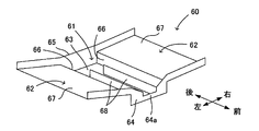
- FIG. 2A is a perspective view of the storage tank 60
- FIG. 2B is a plan view of the storage tank 60.
- the flow of condensed water is indicated by arrows.
- the storage tank 60 includes a storage unit 61 that stores condensed water, and a recovery unit 62 that is formed on both the left and right sides of the storage unit 61 and collects condensed water and flows down to the storage unit 61.
- the storage unit 61 includes a bottom surface 63, a wall body 64 erected at the front end of the bottom surface 63, a wall body 65 erected at the rear end of the bottom surface 63, and a pair of erections at both left and right ends of the bottom surface 63.
- the wall body 66 is formed.
- the collection unit 62 is formed by a slope 67 inclined downward toward the storage unit 61 and wall bodies 64 and 65.
- Both the storage unit 61 and the recovery unit 62 are open to the atmosphere above, and are configured to promote heat exchange between the condensed water and the atmosphere. Moreover, heat exchange can be promoted by making the material of the storage tank 60 into a thing with high heat conductivity, such as copper.
- the central part in the left-right direction of the wall body 64 is a weir 64a having a height lower than that of the other parts of the wall body 64 and the other wall bodies 65 and 66. For this reason, if condensed water accumulates in the storage part 61 to the height of the weir 64a, the condensed water passes over the weir 64a and flows out of the storage tank 60. That is, by providing the weir 64a, the position where the condensed water flows out of the storage tank 60 can be easily defined. Moreover, the liquid film thickness of the condensed water stored in the storage part 61 can be prescribed
- the residence time of the condensed water in the storage unit 61 becomes longer, the amount of heat exchange between the condensed water in the storage unit 61 and the atmosphere increases, and the condensed water can be heated to a higher temperature.
- the height of the partition 68 can be set freely. However, if the height of the partition 68 is set higher than the weir 64a, the condensed water goes over the partition 68 and goes directly to the weir 64a. This is preferable because it can be surely prevented.
- the storage tank 60 as shown in FIGS. 2A and 2B is adopted as the first storage tank 60A, the second storage tank 60B and 60C, and the condensed water flowing out from the weir 64a flows down to the gas pipe 50. If it arranges to do, it is enough.
- a plurality of first storage tanks 60 ⁇ / b> A are also provided in correspondence with the plurality of intermediate medium heaters 10.
- a gutter member 70 is provided in order to collect the condensed water from the plurality of first storage tanks 60 ⁇ / b> A and flow down to the gas pipe 50.
- the flange member 70 will be described.
- the 2nd storage tank 60B or 60C is provided with two or more, you may provide the member similar to the eaves member 70 with respect to the 2nd storage tank 60B and 60C.
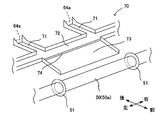
- FIG. 3 is a plan view showing the arrangement of the first storage tank 60A and the eaves member 70
- FIG. 4 is a perspective view showing a part of the eaves member 70 in detail.
- the flow of condensed water is indicated by arrows.
- six sets of two intermediate medium warmers 10 are arranged side by side, and one first storage tank 60 ⁇ / b> A is provided for each set of the intermediate medium warmer 10. It is arranged vertically below.
- the dredging member 70 which collects the condensed water which flowed out from each 1st storage tank 60A, and guides it to the 1st heating part 50a of the gas piping 50 is provided.
- the eaves member 70 includes six receiving portions 71 that receive the condensed water flowing out from each first storage tank 60 ⁇ / b> A, a merging portion 72 to which the six receiving portions 71 are connected, and a front side from the left and right central portion of the merging portion 72. And an inclined portion 73 extending in the direction. The inclined portion 73 is inclined downward toward the gas pipe 50.
- Each receiving part 71 is connected to the weir 64 a of the first storage tank 60 ⁇ / b> A, receives the condensed water that has passed over the weir 64 a, and guides the condensed water to the joining part 72.
- the condensed water collected in the merging portion 72 flows down from the inclined portion 73 to the first heating portion 50a of the gas pipe 50.
- a weir 74 is provided at the boundary between the merging portion 72 and the inclined portion 73, and the condensed water that has passed over the weir 74 flows down the inclined portion 73.
- merging part 72 can be lengthened.
- two collar-shaped water stop portions 51 are provided on the outer peripheral surface of the gas pipe 50. The two water stop portions 51 are formed at positions slightly outside the left and right ends of the inclined portion 73 in a top view.
- the water stop part 51 By providing such a water stop part 51, it is possible to prevent the condensed water flowing down from the inclined part 73 to the gas pipe 50 from flowing outside the water stop part 51 in the axial direction of the gas pipe 50. The re-collection of the condensed water by the storage tank 60B becomes easy.
- the water stop part 51 should just be provided only in the lower side.
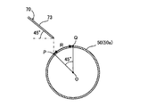
- FIG. 5 is a cross-sectional view for explaining a preferred arrangement of the eaves member 70. Specifically, the positional relationship between the inclined portion 73 and the gas pipe 50 in a cross section orthogonal to the axial direction of the gas pipe 50 is shown.
- FIG. An intersection point P between the gas pipe 50 and a straight line extending vertically downward from the tip of the inclined portion 73 is a range R of 45 degrees in the circumferential direction from the apex Q of the gas pipe 50 to the base end side (left side in the figure) of the inclined portion 73. It is preferable to be located within.
- the condensed water flowing down the inclined portion 73 flows almost evenly on both the left and right sides of the gas pipe 50, so that the natural gas NG in the gas pipe 50 can be uniformly heated.
- the eaves member 70 is arranged so that the inclination angle of the inclined portion 73 from the horizontal plane is 45 degrees and the position of the intersection P is 45 degrees from the apex Q (the left end of the range R). By doing so, the condensed water can be made to flow evenly to the left and right sides more reliably.
- the condensed water flowing out from the plurality of first storage tanks 60A can be collected and allowed to flow down to the first heating unit 50a of the gas pipe 50. it can. However, it is not essential to provide such a saddle member 70, and the condensed water may flow down from each first storage tank 60A to the gas pipe 50 individually.
- Condensed water stored in the storage tank 60 can be heated to substantially the same temperature as the outside air temperature only by exchanging heat with the atmosphere by ensuring sufficient residence time in the storage unit 61.
- bottom area the area of the bottom surface 63 of the reservoir 61 (hereinafter simply referred to as “bottom area”) is too small, the inflowing condensed water will flow out of the weir 64a without being sufficiently heated. Therefore, the bottom area of the reservoir 61 that can be raised to the same temperature as the outside air temperature while the condensed water stays in the reservoir 61 is derived.
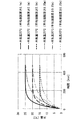
- the six conditions in total are combinations of three conditions (25 ° C., 20 ° C., 15 ° C.) of the outside air temperature and two conditions (0.1 m, 0.25 m) of the average liquid film thickness.
- the result is shown in FIG.
- the time required for water at 0 ° C. to reach the same temperature as the outside air temperature is hardly affected by the outside air temperature, but can be greatly affected by the thickness of the liquid film. I understood.
- the average liquid film thickness of the condensed water in the reservoir 61 is t [m]
- the amount of condensed water generated per unit time is Q [m 3 / min]
- the bottom area of the reservoir 61 is S [ m 2 ]
- the required residence time T [min] is calculated from the approximate expression shown in FIG. T ⁇ 2044t-16.2 It is.
- St / Q [min] the condensed water in the storage unit 61 is replaced with newly generated condensed water.
- St / Q ⁇ 2044t-16.2 It is necessary to satisfy.
- the condensed water in the storage part 61 can be raised to the temperature substantially the same as external temperature.
- the height of the weir 64a may be used as the average liquid film thickness t.
- the liquefied gas vaporizer 1 includes a thermometer 80 for measuring the temperature of the natural gas NG in the gas pipe 50 on the downstream side of the vaporized gas heater 30, and a vaporized gas heater based on the measured value by the thermometer 80.
- Control means 90 for controlling the operation of the warmer 30 is further provided.
- thermometer 80 is provided further downstream than the third heating unit 50c of the gas pipe 50, and the measured value by the thermometer 80 is constant at the target temperature of natural gas NG of 5 ° C. Is preferred. Therefore, the control unit 90 feedback-controls the motor 33 of the vaporized gas warmer 30 so that the value measured by the thermometer 80 is constant at 5 ° C. By doing so, the natural gas NG can be reliably maintained at the target temperature of 5 ° C.
- the third warming part located on the most downstream side.
- a thermometer 80 is provided further downstream than the warm part 50c. That is, even if the degree of warming of the natural gas NG in the first warming part 50a, the second warming part 50b, and the third warming part 50c changes due to fluctuations in the outside air temperature, etc. The feedback control considering all of the above is executed. For this reason, the temperature of the natural gas NG can be reliably maintained at the target temperature.
- the position of the thermometer 80 is not limited to this.
- a storage tank 60 shown in FIGS. 8A and 8B is obtained by changing the shape of the partition 68 provided in the storage unit 61. Specifically, a meandering flow path is formed in the storage portion 61 by making the partition 68 have a shape in which a plurality of flow paths of condensed water are folded back. For this reason, the flow path from the position where the condensed water flows into the storage portion 61 to the weir 64a becomes longer, and the residence time of the condensed water can be increased.
- the height of the condensed water flow path formed by the partition 68 is higher than the walls 64, 65, 66 and the partition 68. It is conceivable to provide an intermediate weir 69 having a low height. 9A and 9B, the partition body 68 is indicated by a thick line in order to clarify the distinction between the partition body 68 and the intermediate weir 69.
- an intermediate weir 69 is provided, in order for the condensed water to reach the weir 64a from the inflow position to the storage portion 61, it is necessary to accumulate the condensed water to a height at which each intermediate weir 69 can be overcome. Thereby, the residence time of the condensed water in the storage part 61 can be further increased.
- the height of the intermediate weir 69 may be basically the same as the height of the weir 64a, but may be different.
- the power consumption of the heater 30 can be reduced.
- the natural gas NG can be raised to the target temperature only by heating with condensed water, the vaporized gas heater 30 can be eliminated.
- the condensed water flows down to the gas pipe 50 only by gravity, no additional power is required.
- the heat of the atmosphere is used to heat the condensed water, no additional power is required for this.
- the condensed water generated on the surface of the heat transfer tube 11 can be effectively used, and the power consumption can be effectively reduced.
- such a liquefied gas vaporization apparatus 1 aims at reduction of power consumption using the heat of air
- FIG. 10 is a schematic diagram showing the overall configuration of the liquefied gas vaporization system.
- the liquefied gas vaporization system 100 condenses the vapor of the working fluid used in binary power generation using the cold heat of the condensed water stored in the first storage tank 60A of the liquefied gas vaporizer 1.
- FIG. 10 is a view of the liquefied gas vaporization system 100 as viewed from the side. However, for convenience, the evaporation unit 102 and the condensing unit 105 have a piping shape viewed from above.
- the liquefied gas vaporization system 100 includes a circulation pipe 101 disposed between the first storage tank 60A provided in the liquefied gas vaporizer 1 and the ground, and the inside of the circulation pipe 101 is used as a working fluid.
- Ammonia is flowing.
- the ammonia circulating in the circulation pipe 101 changes in phase between, for example, ammonia gas having a temperature of 10 ° C. and a pressure of 0.8 MPa and liquefied ammonia having a temperature of 10 ° C. and a pressure of 0.1 MPa.
- the working fluid is not limited to ammonia, and any other fluid may be used as long as it is a fluid that changes phase between a gas phase and a liquid phase at room temperature.
- the liquefied gas vaporization system 100 is further connected to an evaporation section 102 that generates ammonia gas by evaporating liquefied ammonia, a turbine 103 that is rotationally driven by the ammonia gas generated by the evaporation section 102, and a rotating shaft of the turbine 103.
- the generator 104 is provided.
- the liquefied gas vaporization system 100 further includes a condensing unit 105 that condenses the ammonia gas discharged from the turbine 103 to generate liquefied ammonia, and a pump 106 for pumping the liquefied ammonia.
- the evaporating unit 102 is configured by folding the circulation pipe 101 a plurality of times around 20 m underground. Since the temperature is maintained substantially constant throughout the year in the ground, a stable power generation amount can be obtained throughout the year by providing the evaporation unit 102 in the ground.
- the range in which the evaporation unit 102 is provided be in a region immediately below the installation range of the plurality of first storage tanks 60A.
- the number of passes of the circulation pipe 101 in the evaporator 102 is about 8 to 10 passes, and the interval between the passes is about 5 m or more.
- the installation depth of the evaporating unit 102 is not limited to the vicinity of 20 m underground, and may be in the range of about 10 to 30 m underground.
- the condensing unit 105 is configured by bending the circulation pipe 101 a plurality of times so that the circulation pipe 101 passes through the plurality of first storage tanks 60A provided a plurality of times.
- the circulation pipe 101 in the condensing unit 105 is configured by connecting ends of two straight pipe parts 101a adjacent to each other by a curved pipe part 101b, and the straight pipe part 101a is a first storage. It passes through the condensed water in the storage part 61 of the tank 60A.
- heat exchange with the condensed water in the storage part 61 of 60 A of 1st storage tanks and the ammonia gas which flows through the circulation piping 101 can be accelerated
- it is preferable that the circulation pipe 101 is completely immersed in the condensed water, but the circulation pipe 101 may partially protrude from the water surface of the condensed water.
- FIG. 11 is a perspective view showing a part of the condensing unit 105, and shows a part related to the first storage tank 60A located in the lower left in FIG. Since the configuration of the first storage tank 60A is basically the same as that shown in FIG. 2A, only the main points will be described here.
- heat exchange is performed between the ammonia gas and the condensed water in a portion of the circulating pipe 101 that passes through the condensed water stored in the storage portion 61 of the first storage tank 60A.
- the ammonia gas is condensed to produce liquefied ammonia, and the temperature of the condensed water rises from 0 ° C. to 5 ° C., for example.
- the function of the condensing unit 105 is lowered when the temperature of the condensed water is increased by heat exchange with the atmosphere.
- at least the storage part 61 of the first storage tank 60 ⁇ / b> A is thermally insulated, and more preferably, the entire first storage tank 60 ⁇ / b> A including the recovery part 62 is thermally insulated.
- the heat insulation construction here includes configuring the first storage tank 60A with stainless steel or resin having a relatively low thermal conductivity, or providing the first storage tank 60A with a heat insulating material.
- the eaves member 70 (see FIG. 3) connected to the downstream side of the first storage tank 60A promotes heat exchange between the condensed water and the atmosphere and raises the temperature of the condensed water. It is preferably composed of high aluminum, copper or the like.
- the efficiency of heat exchange with the ammonia gas in the circulation pipe 101 improves as new condensed water is sequentially supplied. Therefore, in order to shorten the residence time of the condensed water in the storage part 61 of the first storage tank 60A, the partition 68 as shown in FIG. 2A may be eliminated, and the volume of the storage part 61 may be reduced.
- the thermal conductivity of the part located outside the storage part 61 of the first storage tank 60A may be made smaller than the thermal conductivity of the part located inside the storage part 61.
- the liquefied gas vaporization system 100 configured as described above, it is possible to generate electric power by using the cold heat of the condensed water generated in the liquefied gas vaporizer 1 and the underground heat (or geothermal heat).
- geothermal heat refers to heat storage in a relatively shallow underground part using solar energy as a heat source.
- geothermal generally refers to heat storage inside the earth (generally deeper than the target area of geothermal heat) derived from volcanic activity. The power thus obtained is used as driving power for the fan 12 of the intermediate medium warmer 10 and the fan 32 (see FIG. 1) of the vaporized gas warmer 30, thereby further reducing the power consumption in the liquefied gas vaporizer 1. It can be effectively reduced.
- FIG. 12 is a graph showing the relationship between the diameter of the circulation pipe 101 (hereinafter simply referred to as “pipe diameter”) and the pressure loss.
- the pressure loss decreases as the pipe diameter increases. Since it is generally desirable to suppress the pressure loss to about 10 kPa or less, the pipe diameter is preferably about 0.05 m or more. On the other hand, if the pipe diameter is larger than the height of the weir 64a of the first storage tank 60A, the circulation pipe 101 comes out of the surface of the condensed water in the storage section 61, so the pipe diameter is the height of the weir 64a (for example, 0). .2m) or less.
- FIG. 13 is a graph showing the relationship between the ammonia flow rate and the pressure loss or the number of passes.
- FIG. 14 is a graph showing the relationship between the ammonia flow rate and pressure loss or exchange heat.
- the pressure loss tends to increase as the ammonia flow rate increases. Further, the maximum amount of heat that the condensed water can exchange heat from the amount of condensed water generated was determined as the maximum amount of condensed water exchanged in the figure. If the ammonia-side exchange heat quantity is less than the condensate maximum exchange heat quantity, some of the cold heat of the condensate is wasted. For this reason, it is preferable that the ammonia flow rate is about 800 kg / h or more so that the exchange heat amount of ammonia is not less than the maximum exchange heat amount of condensed water.
- FIG. 15 is a graph showing the relationship between the ammonia flow rate and pressure loss or exchange heat.
- the calculation conditions are almost the same as those in FIG. 14 except that the pipe diameter is 0.05 m.
- the pipe diameter is 0.05 m, it is necessary to increase the number of passes because the exchange heat quantity on the ammonia side cannot be made equal to or greater than the maximum exchange heat quantity of condensed water while suppressing the pressure loss to 10 kPa or less.
- the condensed water generated on the surface of the heat transfer pipe 11 is collected in the first storage tank 60 ⁇ / b> A collected before flowing down to the gas pipe 50, and the condensed water is flowed down to the gas pipe 50.
- the second storage tanks 60B and 60C for collecting water again are further provided.
- only one of the first storage tank and the second storage tank may be provided as the storage tank 60, and the number of the second storage tanks is not limited to two, but one or three or more. It may be.
- the gas pipe 50 is arranged vertically below the heat transfer pipe 11 of the intermediate medium heater 10, and the gas is directly supplied from the heat transfer pipe 11. It is conceivable that the condensed water dropped on the pipe 50 is collected in the second storage tank.
- the vaporized gas warmer 30 which heats the natural gas NG in the gas piping 50 was provided, the natural gas NG in the gas piping 50 reaches target temperature only by the heating by condensed water.
- the vaporized gas heater 30 may be omitted.
- the vaporized gas heater 30 is not limited to the air temperature type, and a heater using a heat medium other than air or a heater may be employed.
- the arrangement position of the vaporized gas heater 30 is not limited to the position illustrated in FIG. 1, and can be set to an appropriate position of the gas pipe 50.
- the specific configuration for collecting the condensed water and flowing it down to the gas pipe 50 can be changed as appropriate.
- the collection unit 62 may not be provided in the storage tank 60, and the entire storage unit 61 may be provided, or a guide member for guiding condensed water to the storage tank 60 may be provided separately.
- a guide member for guiding condensed water to the storage tank 60 may be provided separately.
- the gas pipe 50 is arranged vertically below the weir 64a of the storage tank 60, and the form reaching the gas pipe 50 by dropping the condensed water flowing out of the storage tank 60 is also "flow down to the gas pipe" in the present invention. It is included in the concept.
- the intermediate medium warmer 10 vaporizes the liquid intermediate medium.
- the intermediate medium heater 10 may simply raise the temperature without changing the phase of the liquid intermediate medium.
Landscapes
- Engineering & Computer Science (AREA)
- Mechanical Engineering (AREA)
- General Engineering & Computer Science (AREA)
- Physics & Mathematics (AREA)
- Thermal Sciences (AREA)
- Geometry (AREA)
- Filling Or Discharging Of Gas Storage Vessels (AREA)
Abstract
液化ガス気化装置は、加温用気体との熱交換により中間媒体加温器で気化させた中間媒体との熱交換によって、液化ガスを気化させて気化ガスを生成する液化ガス蒸発器と、液化ガス蒸発器で生成された気化ガスが流れるガス配管と、を設ける。液化ガス気化装置は、伝熱管の表面で発生した凝縮水を、伝熱管よりも低い位置に配置された貯留タンクに貯留した状態で大気との熱交換によって加温した後、貯留タンクよりも低い位置にあるガス配管へ流下させることで、ガス配管内の気化ガスを加温する。
Description
本発明は、中間媒体との熱交換によって液化ガスを気化させる液化ガス気化装置および液化ガス気化システムに関する。
中間媒体との熱交換によって液化ガスを気化させる液化ガス気化装置として、例えば特許文献1に記載されているものがある。この液化ガス気化装置では、中間媒体が中間媒体蒸発部と液化ガス気化部との間を循環しており、中間媒体蒸発部で気化された中間媒体が液化ガス気化部で凝縮することにより、低温の液化ガスが気化して気化ガスを生成する。かかる構成によれば、中間媒体の凝縮潜熱を利用して液化ガスを気化させることになるため、潜熱/顕熱のエンタルピー比に応じて、中間媒体の循環量を低減することができるとされている。
ところで、上述の液化ガス気化装置は、中間媒体蒸発部の伝熱管の周囲に大気を流通させることで、伝熱管内の中間媒体を気化させている。この際、大気に含まれる水蒸気が伝熱管の表面で凝縮し、凝縮水が発生する。こうして生じた凝縮水は、特に利用されることなく、廃棄されるのが一般的であり、凝縮水を有効に活用する方法が求められていた。
一方、液化ガス気化部で気化された気化ガスは、加温器により所定の目標温度まで加温されるのが一般的であるが、加温器を作動させるには追加的な電力が必要となる。そこで、できる限り加温器における負荷を減らし、場合によっては、加温器をなくすことによって、液化ガス気化装置における消費電力を低減したいという要求がある。
このような現状に鑑みて、本発明は、中間媒体を用いた液化ガス気化装置および液化ガス気化システムにおいて、中間媒体が流れる伝熱管の表面に発生する凝縮水を有効活用し、消費電力を効果的に低減することを目的としたものである。
上記目的を達成するため、本発明にかかる液化ガス気化装置は、加温用気体との熱交換によって、伝熱管内を流れる中間媒体を加温する中間媒体加温器と、前記中間媒体加温器で加温された前記中間媒体との熱交換によって、液化ガスを気化させて気化ガスを生成する液化ガス蒸発器と、前記液化ガス蒸発器で生成された前記気化ガスが流れるガス配管と、を備え、前記加温用気体が水蒸気を含み、前記伝熱管の表面温度が前記加温用気体の露点よりも低くなっていることで、前記伝熱管の表面で凝縮水が発生しており、前記凝縮水を、前記伝熱管よりも低い位置に配置された貯留タンクの貯留部に貯留した状態で大気との熱交換によって加温した後、前記貯留タンクよりも低い位置にある前記ガス配管へ流下させることで、前記ガス配管内の前記気化ガスを加温することを特徴とする。
本発明では、中間媒体加温器の伝熱管の表面に発生した凝縮水が、貯留タンクの貯留部に貯留された状態で、大気との熱交換によって加温される。そして、加温された凝縮水がガス配管へ流下されることで、ガス配管内の気化ガスが加温される。こうして、凝縮水を利用することで、気化ガスの加温に必要な電力を低減することができる。しかも、伝熱管、貯留タンク、ガス配管は高い方から低い方へとこの順番で配置されているので、凝縮水を重力のみで流下させることが可能であり、追加的な電力を要しない。また、凝縮水の加温には、大気の熱を利用しているため、これにも追加的な電力を要しない。つまり、本発明によれば、伝熱管の表面に発生する凝縮水を有効活用し、消費電力を効果的に低減することが可能となる。
本発明にかかる液化ガス気化装置の実施形態について、図面を参照しつつ説明する。なお、本実施形態では、中間媒体としてプロパンを使用し、液化天然ガス(LNG:Liquefied Natural Gas)を気化させて天然ガス(NG:Natural Gas)を生成する場合について説明するが、中間媒体や気化対象とする液化ガスはこれに限定されない。例えば、中間媒体として、プロピレン、代替フロン等の、常温で蒸発し、かつ常用の温度(低温)で固化しない媒体(大気の温度よりも沸点の低い媒体)を用いてもよいし、ブライン等の不凍液を用いてもよい。また、気化対象とする液化ガスは、エチレン、液化酸素、液化窒素等の低温液化ガスであってもよい。
(液化ガス気化装置の全体構成)
図1は、本実施形態にかかる液化ガス気化装置1の全体構成を示す。液化ガス気化装置1は、液体プロパンLPを気体プロパンGPへと気化させる中間媒体加温器10と、気体プロパンGPが凝縮する際の凝縮熱により、液化天然ガスLNGを気化させて天然ガスNGを生成する液化ガス蒸発器20と、液化ガス蒸発器20よりも下流側に配置され、天然ガスNGを加温する気化ガス加温器30と、を有する。
図1は、本実施形態にかかる液化ガス気化装置1の全体構成を示す。液化ガス気化装置1は、液体プロパンLPを気体プロパンGPへと気化させる中間媒体加温器10と、気体プロパンGPが凝縮する際の凝縮熱により、液化天然ガスLNGを気化させて天然ガスNGを生成する液化ガス蒸発器20と、液化ガス蒸発器20よりも下流側に配置され、天然ガスNGを加温する気化ガス加温器30と、を有する。
中間媒体加温器10と液化ガス蒸発器20との間には、循環配管40が配設されている。循環配管40に設けられたポンプ41を作動させることで、中間媒体であるプロパンが循環配管40を流通する。また、液化天然ガスLNGの供給源(不図示)から、液化ガス蒸発器20、気化ガス加温器30を経由し、装置外部のガスタンク(不図示)へと至るまで、ガス配管50が配設されている。液化ガス蒸発器20で生成された天然ガスNGは、ガス配管50を流通して最終的にガスタンクへと至る。
以上のような構成により、ガス配管50に供給される低温の液化天然ガスLNGが、液化ガス蒸発器20にて気化して天然ガスNGとなり、その後、気化ガス加温器30によって加温される。さらに、液化ガス気化装置1では、気化ガス加温器30だけではなく、中間媒体加温器10で発生する凝縮水を利用して天然ガスNGを加温することで、気化ガス加温器30における消費電力の低減を図っている。この点については、後で詳細に説明する。なお、以下の説明においては、大気の温度を一例として25℃としている。
(中間媒体加温器)
中間媒体加温器10は、循環配管40の一部を構成する伝熱管11と、伝熱管11の上方に配置されたファン12と、ファン12を回転駆動するモーター13とを有する。伝熱管11に導入される0℃の液体プロパンLPは、ファン12の回転により外部から取り込まれた大気(加温用気体)との熱交換により気化し、0℃の気体プロパンGPとなる。この熱交換により、大気の温度は、25℃から20℃へと低下する。なお、熱交換の効率を高めるため、伝熱管11を蛇行状に配置したり、伝熱管11にフィンを設けたりするのが一般的である(以下の伝熱管22、31も同様)。
中間媒体加温器10は、循環配管40の一部を構成する伝熱管11と、伝熱管11の上方に配置されたファン12と、ファン12を回転駆動するモーター13とを有する。伝熱管11に導入される0℃の液体プロパンLPは、ファン12の回転により外部から取り込まれた大気(加温用気体)との熱交換により気化し、0℃の気体プロパンGPとなる。この熱交換により、大気の温度は、25℃から20℃へと低下する。なお、熱交換の効率を高めるため、伝熱管11を蛇行状に配置したり、伝熱管11にフィンを設けたりするのが一般的である(以下の伝熱管22、31も同様)。
(液化ガス蒸発器)
液化ガス蒸発器20は、循環配管40から気体プロパンGPが供給される熱交換室21と、ガス配管50の一部を構成し、熱交換室21に配置される伝熱管22と、熱交換室21の下方に形成される液貯留部23とを有する。伝熱管22に導入される-160℃の液化天然ガスLNGと、熱交換室21に供給される0℃の気体プロパンGPとの間で熱交換が行われることで、伝熱管22内の液化天然ガスLNGが気化して-5℃の天然ガスNGが生成されるとともに、気体プロパンGPが凝縮して0℃の液体プロパンLPが液貯留部23に貯留される。
液化ガス蒸発器20は、循環配管40から気体プロパンGPが供給される熱交換室21と、ガス配管50の一部を構成し、熱交換室21に配置される伝熱管22と、熱交換室21の下方に形成される液貯留部23とを有する。伝熱管22に導入される-160℃の液化天然ガスLNGと、熱交換室21に供給される0℃の気体プロパンGPとの間で熱交換が行われることで、伝熱管22内の液化天然ガスLNGが気化して-5℃の天然ガスNGが生成されるとともに、気体プロパンGPが凝縮して0℃の液体プロパンLPが液貯留部23に貯留される。
(気化ガス加温器)
気化ガス加温器30は、ガス配管50の一部を構成する伝熱管31と、伝熱管31の上方に配置されたファン32と、ファン32を回転駆動するモーター33とを有する。伝熱管31に導入される-4℃の天然ガスNGは、ファン32の回転により外部から取り込まれた大気との熱交換により、4.5℃まで昇温する。この熱交換により、大気の温度は、25℃から20℃へと低下する。
気化ガス加温器30は、ガス配管50の一部を構成する伝熱管31と、伝熱管31の上方に配置されたファン32と、ファン32を回転駆動するモーター33とを有する。伝熱管31に導入される-4℃の天然ガスNGは、ファン32の回転により外部から取り込まれた大気との熱交換により、4.5℃まで昇温する。この熱交換により、大気の温度は、25℃から20℃へと低下する。
(貯留タンク)
上述のように、中間媒体加温器10の伝熱管11には、0℃の液体プロパンLPまたは気体プロパンGPが流通しているため、伝熱管11の表面温度は0℃に近い温度となる。その結果、伝熱管11の表面温度が大気の露点よりも低くなり、伝熱管11の表面にて大気中の水蒸気が凝縮し、凝縮水が発生する。液化ガス気化装置1においては、この凝縮水を利用してガス配管50内の天然ガスNGを加温するため、3つの貯留タンク60A、60B、60Cが設けられている。なお、図1では、ブロック矢印により、凝縮水の流れを模式的に示している。
上述のように、中間媒体加温器10の伝熱管11には、0℃の液体プロパンLPまたは気体プロパンGPが流通しているため、伝熱管11の表面温度は0℃に近い温度となる。その結果、伝熱管11の表面温度が大気の露点よりも低くなり、伝熱管11の表面にて大気中の水蒸気が凝縮し、凝縮水が発生する。液化ガス気化装置1においては、この凝縮水を利用してガス配管50内の天然ガスNGを加温するため、3つの貯留タンク60A、60B、60Cが設けられている。なお、図1では、ブロック矢印により、凝縮水の流れを模式的に示している。
具体的には、中間媒体加温器10の伝熱管11の下方に第1貯留タンク60Aを配置し、伝熱管11の表面に発生する凝縮水を第1貯留タンク60Aで回収する。そして、第1貯留タンク60Aに貯留されている凝縮水は、大気との熱交換により15℃まで加温される。加温された凝縮水は、第1貯留タンク60Aよりも下方に位置するガス配管50の第1加温部50aに流下する。こうすることで、第1加温部50aにおいて、天然ガスNGを-5℃から-4.5℃に昇温させることができる。この際、凝縮水の温度は、15℃から10℃に低下する。
また、第1加温部50aの下方に第2貯留タンク60Bを配置し、第1加温部50aから滴下する凝縮水を第2貯留タンク60Bで再回収する。そして、第2貯留タンク60Bに貯留されている凝縮水は、大気との熱交換により再び15℃まで加温される。加温された凝縮水は、第2貯留タンク60Bよりも下方に位置するガス配管50の第2加温部50bに流下する。こうすることで、第2加温部50bにおいて、天然ガスNGを-4.5℃から-4℃に昇温させることができる。この際、凝縮水の温度は、15℃から10℃に低下する。
さらに、第2加温部50bの下方にもう1つの第2貯留タンク60Cを配置し、第2加温部50bから滴下する凝縮水を第2貯留タンク60Cで再回収する。そして、第2貯留タンク60Cに貯留されている凝縮水は、大気との熱交換により再び15℃まで加温される。加温された凝縮水は、第2貯留タンク60Cよりも下方に位置するガス配管50の第3加温部50cに流下する。こうすることで、第3加温部50cにおいて、天然ガスNGを4.5℃から5℃に昇温させることができる。この際、凝縮水の温度は、15℃から10℃に低下する。
以上のように、貯留タンク60A、60B、60Cで回収した凝縮水を、大気との熱交換により加温し、ガス配管50に流下させることで、第1加温部50a、第2加温部50b、第3加温部50cのそれぞれで、天然ガスNGを0.5℃ずつ昇温させることができる。したがって、天然ガスNGを目標温度(ここでは5℃)まで上昇させるにあたって、気化ガス加温器30の負荷を1.5℃分低減することができ、その結果、気化ガス加温器30における消費電力を低減することが可能となる。
なお、第1貯留タンク60Aは、伝熱管11の表面で発生した凝縮水を、ガス配管50へ流下させる前に回収し、他方、第2貯留タンク60B、60Cは、ガス配管50へ流下させた凝縮水を再び回収する。この点で、両者は異なる。しかしながら、凝縮水を回収、貯留、加温するという点においては、両者に特に相違はない。そこで、以下の説明では、第1貯留タンク60Aと、第2貯留タンク60B、60Cとを特に区別しない場合には、単に「貯留タンク60」と称する。
(貯留タンクの具体構成)
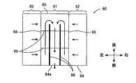
続いて、貯留タンク60の具体構成について説明する。図2Aは、貯留タンク60の斜視図であり、図2Bは、貯留タンク60の平面図である。なお、図2Bでは、凝縮水の流れを矢印で示している。
続いて、貯留タンク60の具体構成について説明する。図2Aは、貯留タンク60の斜視図であり、図2Bは、貯留タンク60の平面図である。なお、図2Bでは、凝縮水の流れを矢印で示している。
貯留タンク60は、凝縮水を貯留する貯留部61と、貯留部61の左右両側に形成され、凝縮水を回収して貯留部61へと流下させる回収部62とを有する。貯留部61は、底面63と、底面63の前端に立設された壁体64と、底面63の後端に立設された壁体65と、底面63の左右両端に立設された一対の壁体66とによって形成される。また、回収部62は、貯留部61に向かって下方に傾斜している斜面67と、壁体64、65とによって形成される。貯留部61、回収部62はともに、上方で大気開放されており、凝縮水と大気との熱交換を促進できるように構成されている。また、貯留タンク60の材料を銅などの熱伝導率の高いものとすることで、熱交換を促進させることができる。
壁体64の左右方向における中央部は、壁体64の他の部分や他の壁体65、66よりも高さが低い堰64aとなっている。このため、凝縮水が堰64aの高さまで貯留部61に溜まると、凝縮水は堰64aを乗り越えて、貯留タンク60から流出する。つまり、堰64aを設けることによって、凝縮水が貯留タンク60から流出する位置を容易に規定できる。また、貯留部61に貯留されている凝縮水の液膜厚さは、堰64aの高さによって規定することができる。
堰64aの左右両端からは、後方に向かって壁体65の手前まで延びる仕切体68が、貯留部61の底面63に2つ立設されている。このため、図2Bに矢印で示すように、回収部62から貯留部61に流入した凝縮水は、一旦後方側へと迂回してから堰64aへと至ることになる。つまり、凝縮水が貯留部61への流入位置から堰64aに直接流れる場合と比べると、仕切体68を設けることによって、凝縮水が上記流入位置から堰64aに至るまでの流路を長くすることができる。その結果、貯留部61における凝縮水の滞留時間が長くなり、貯留部61内の凝縮水と大気との熱交換量が増大し、凝縮水をより高い温度まで加温することが可能となる。なお、仕切体68の高さは自由に設定することができるが、仕切体68の高さを堰64aよりも高くしておけば、凝縮水が仕切体68を乗り越えて堰64aへと直接向かうことを確実に防止できるので好適である。
(樋部材)
基本的には、図2A、2Bに示したような貯留タンク60を、第1貯留タンク60A、第2貯留タンク60B、60Cとして採用し、堰64aから流出した凝縮水がガス配管50へと流下するように配置すれば、それで足りる。しかしながら、本実施形態では、図3に示すように、中間媒体加温器10が複数設けられていることに対応し、第1貯留タンク60Aも複数設けられている。そこで、複数の第1貯留タンク60Aからの凝縮水を集めてガス配管50へと流下させるため、樋部材70が設けられている。以下、この樋部材70について説明する。なお、第2貯留タンク60Bあるいは60Cが複数設けられている場合には、樋部材70と同様の部材を、第2貯留タンク60B、60Cに対して設けてもよい。
基本的には、図2A、2Bに示したような貯留タンク60を、第1貯留タンク60A、第2貯留タンク60B、60Cとして採用し、堰64aから流出した凝縮水がガス配管50へと流下するように配置すれば、それで足りる。しかしながら、本実施形態では、図3に示すように、中間媒体加温器10が複数設けられていることに対応し、第1貯留タンク60Aも複数設けられている。そこで、複数の第1貯留タンク60Aからの凝縮水を集めてガス配管50へと流下させるため、樋部材70が設けられている。以下、この樋部材70について説明する。なお、第2貯留タンク60Bあるいは60Cが複数設けられている場合には、樋部材70と同様の部材を、第2貯留タンク60B、60Cに対して設けてもよい。
図3は、第1貯留タンク60Aおよび樋部材70の配置を示す平面図であり、図4は、樋部材70の一部を詳細に示す斜視図である。なお、図3では、凝縮水の流れを矢印で示している。本実施形態では、2つの中間媒体加温器10からなる組が左右に6組並べられて配置されており、各組に対して1つの第1貯留タンク60Aが、中間媒体加温器10の鉛直下方に配置されている。そして、各第1貯留タンク60Aから流出した凝縮水を集め、ガス配管50の第1加温部50aへと案内する樋部材70が設けられる。
樋部材70は、各第1貯留タンク60Aから流出した凝縮水を受け止める6つの受止部71と、6つの受止部71が接続される合流部72と、合流部72の左右中央部から前方に延設された傾斜部73とを有する。傾斜部73は、ガス配管50に向かって下方に傾斜している。各受止部71は、第1貯留タンク60Aの堰64aに接続されており、堰64aを乗り越えた凝縮水を受け止めて、合流部72へと凝縮水を導く。合流部72に集められた凝縮水は、傾斜部73からガス配管50の第1加温部50aへと流下する。
図4に示すように、合流部72と傾斜部73との境界には堰74が立設されており、この堰74を乗り越えた凝縮水が傾斜部73を流下する。堰74を設けることで、受止部71および合流部72での凝縮水の滞留時間を長くすることができる。また、ガス配管50の外周面には、つば状の止水部51が2つ設けられる。2つの止水部51は、上面視で傾斜部73の左右両端よりも少しだけ外側の位置に形成されている。このような止水部51を設けることで、傾斜部73からガス配管50に流下した凝縮水が、ガス配管50の軸方向において止水部51の外側に流れてしまうことを防止でき、第2貯留タンク60Bによる凝縮水の再回収が容易となる。なお、ガス配管50が軸方向に傾斜配置されている場合には、下側にだけ止水部51を設ければよい。
図5は、樋部材70の好適な配置を説明するための断面図であり、具体的には、ガス配管50の軸方向に直交する断面における、傾斜部73とガス配管50との位置関係を示す図である。傾斜部73の先端から鉛直下方におろした直線とガス配管50との交点Pが、ガス配管50の頂点Qから傾斜部73の基端側(図中左側)へ周方向に45度の範囲R内に位置すると好適である。こうすることで、傾斜部73を流下してきた凝縮水が、ガス配管50の左右両側に概ね均等に流れるため、ガス配管50内の天然ガスNGを均一に加温することができるからである。特に、図5に示すように、傾斜部73の水平面からの傾斜角度を45度とし、交点Pの位置が頂点Qから45度の位置(範囲Rの左端)となるように樋部材70を配置すれば、より確実に凝縮水を左右両側に均等に流れさせることができる。
以上説明してきた樋部材70を第1貯留タンク60Aに対して設けることで、複数の第1貯留タンク60Aから流出した凝縮水を集めてガス配管50の第1加温部50aに流下させることができる。しかしながら、このような樋部材70を設けることは必須ではなく、各第1貯留タンク60Aから個々にガス配管50へと凝縮水を流下させるようにしてもよい。
(貯留部の必要底面積の導出)
貯留タンク60に貯留されている凝縮水は、貯留部61での滞留時間を十分に確保することで、大気との熱交換だけで外気温とほぼ同じ温度まで昇温させることができる。ただし、貯留部61の底面63の面積(以下、単に「底面積」と称する)が小さすぎると、流入してくる凝縮水が、十分に加温されないまま堰64aから流出してしまう。そこで、凝縮水が貯留部61に滞留している間に、外気温と同じ温度まで昇温させることが可能な貯留部61の底面積を導出する。
貯留タンク60に貯留されている凝縮水は、貯留部61での滞留時間を十分に確保することで、大気との熱交換だけで外気温とほぼ同じ温度まで昇温させることができる。ただし、貯留部61の底面63の面積(以下、単に「底面積」と称する)が小さすぎると、流入してくる凝縮水が、十分に加温されないまま堰64aから流出してしまう。そこで、凝縮水が貯留部61に滞留している間に、外気温と同じ温度まで昇温させることが可能な貯留部61の底面積を導出する。
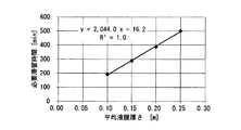
本出願人は、0℃の水を大気との熱交換により加温する実験を、計6通りの条件下で実施した。この計6通りの条件は、外気温の3条件(25℃、20℃、15℃)、平均液膜厚さの2条件(0.1m、0.25m)の組み合わせである。その結果を図6に示す。図6の結果から明らかなように、0℃の水が外気温と同じ温度になるまでに要する時間は、外気温の影響をほとんど受けないが、液膜の厚さの影響を大きく受けることが分かった。
そこで、この実験結果をもとに、0℃の水が外気温と同じ温度になるまでに必要な滞留時間を、平均液膜厚さの関数として近似的に表すことを試みた。この際、平均液膜厚さが0.15m、0.2mの場合についても、追加的に実験データを取得した。その結果、図7に示す4データに適合する近似式として、図中に示す式が得られた。この近似式の相関係数はR2=1.0であり、近似式が実験データによく適合していることを示している。
ここで、貯留部61内の凝縮水の平均液膜厚さをt[m]、単位時間あたりに発生する凝縮水の量をQ[m3/min]、貯留部61の底面積をS[m2]とするとき、必要滞留時間T[min]は、図7に示した近似式より、
T≧2044t-16.2
である。
St/Q[min]だけ時間が経過すると、貯留部61内の凝縮水は新しく発生した凝縮水と入れ替わるため、
St/Q≧2044t-16.2
を満たす必要がある。
この式を変形することで、貯留部61の必要底面積を規定する次式(1)が得られる。
S≧(2044-16.2/t)Q・・・式(1)
式(1)を満たす底面積を有する貯留部61であれば、貯留部61内の凝縮水を外気温とほぼ同じ温度まで上昇させることができる。なお、貯留タンク60の実際の設計にあたっては、平均液膜厚さtとして堰64aの高さを用いればよい。
T≧2044t-16.2
である。
St/Q[min]だけ時間が経過すると、貯留部61内の凝縮水は新しく発生した凝縮水と入れ替わるため、
St/Q≧2044t-16.2
を満たす必要がある。
この式を変形することで、貯留部61の必要底面積を規定する次式(1)が得られる。
S≧(2044-16.2/t)Q・・・式(1)
式(1)を満たす底面積を有する貯留部61であれば、貯留部61内の凝縮水を外気温とほぼ同じ温度まで上昇させることができる。なお、貯留タンク60の実際の設計にあたっては、平均液膜厚さtとして堰64aの高さを用いればよい。
(気化ガス加温器のフィードバック制御)
気化ガス加温器30のフィードバック制御について、図1に戻って説明する。液化ガス気化装置1には、気化ガス加温器30よりも下流側のガス配管50内の天然ガスNGの温度を測定する温度計80、および、温度計80による測定値に基づいて気化ガス加温器30の動作を制御する制御手段90がさらに設けられている。
気化ガス加温器30のフィードバック制御について、図1に戻って説明する。液化ガス気化装置1には、気化ガス加温器30よりも下流側のガス配管50内の天然ガスNGの温度を測定する温度計80、および、温度計80による測定値に基づいて気化ガス加温器30の動作を制御する制御手段90がさらに設けられている。
詳細には、温度計80はガス配管50の第3加温部50cよりもさらに下流側に設けられており、温度計80による測定値は、天然ガスNGの目標温度5℃で一定であることが好ましい。そこで、制御手段90は温度計80による測定値が5℃で一定となるように、気化ガス加温器30のモーター33をフィードバック制御する。こうすることで、天然ガスNGを確実に目標温度の5℃に維持することができる。
特に、本実施形態では、凝縮水による天然ガスNGの加温が行われる第1加温部50a、第2加温部50b、第3加温部50cのうち、最も下流側にある第3加温部50cよりもさらに下流側に温度計80を設けている。つまり、外気温の変動等により、第1加温部50a、第2加温部50b、第3加温部50cにおける天然ガスNGの加温の程度に変動が生じた場合であっても、それをすべて考慮したフィードバック制御が実行されることになる。このため、天然ガスNGの温度を確実に目標温度で一定に維持することができる。ただし、温度計80の位置は、これに限定されるものではない。
(貯留タンクの変形例)
図8A、8B、9A、9Bを参照しつつ、貯留タンク60の変形例について説明する。なお、これらの図では、凝縮水の流れを矢印で示している。
図8A、8B、9A、9Bを参照しつつ、貯留タンク60の変形例について説明する。なお、これらの図では、凝縮水の流れを矢印で示している。
図8A、8Bに示す貯留タンク60は、貯留部61に設けられる仕切体68の形状を変更したものである。具体的には、仕切体68を、凝縮水の流路を複数回折り返した形状とすることで、貯留部61内に蛇行状の流路を形成している。このため、凝縮水が貯留部61への流入位置から堰64aに至るまでの流路がより長くなり、凝縮水の滞留時間を増加させることができる。
凝縮水の滞留時間を増加させるさらなる工夫として、図9A、9Bに示すように、仕切体68によって形成される凝縮水の流路上に、壁体64、65、66や仕切体68よりも高さが低い中間堰69を設けることが考えられる。なお、図9A、9Bでは、仕切体68と中間堰69との区別を明確にするため、仕切体68を太線で示している。このような中間堰69を設けると、凝縮水が貯留部61への流入位置から堰64aに至るには、各中間堰69を乗り越えることができる高さまで凝縮水が溜まる必要がある。これにより、貯留部61における凝縮水の滞留時間を一層増加させることが可能となる。なお、中間堰69の高さは、基本的に堰64aの高さと同じにすればよいが、異なっていてもよい。
(効果)
以上のように、本実施形態の液化ガス気化装置1によれば、中間媒体加温器10の伝熱管11の表面に発生した凝縮水を利用することで、天然ガスNGを加温する気化ガス加温器30の消費電力を低減することができる。さらに、凝縮水による加温だけで天然ガスNGを目標温度まで昇温させることができるのであれば、気化ガス加温器30をなくすことも可能である。しかも、凝縮水を重力のみでガス配管50に流下させているので、追加的な電力を要しない。また、凝縮水の加温には、大気の熱を利用しているため、これにも追加的な電力を要しない。つまり、液化ガス気化装置1によれば、伝熱管11の表面に発生する凝縮水を有効活用し、消費電力を効果的に低減することが可能となる。なお、このような液化ガス気化装置1は、大気の熱を利用して消費電力の低減を図るものであり、特に温暖な地域での使用に適している。
以上のように、本実施形態の液化ガス気化装置1によれば、中間媒体加温器10の伝熱管11の表面に発生した凝縮水を利用することで、天然ガスNGを加温する気化ガス加温器30の消費電力を低減することができる。さらに、凝縮水による加温だけで天然ガスNGを目標温度まで昇温させることができるのであれば、気化ガス加温器30をなくすことも可能である。しかも、凝縮水を重力のみでガス配管50に流下させているので、追加的な電力を要しない。また、凝縮水の加温には、大気の熱を利用しているため、これにも追加的な電力を要しない。つまり、液化ガス気化装置1によれば、伝熱管11の表面に発生する凝縮水を有効活用し、消費電力を効果的に低減することが可能となる。なお、このような液化ガス気化装置1は、大気の熱を利用して消費電力の低減を図るものであり、特に温暖な地域での使用に適している。
また、本実施形態では、貯留タンク60として、伝熱管11の表面で発生した凝縮水をガス配管50へ流下させる前に回収する第1貯留タンク60Aに加えて、ガス配管50へ流下させた凝縮水を再び回収する第2貯留タンク60B、60Cがさらに設けられている。このため、凝縮水を利用した天然ガスNGの加温を複数回行うことができ、消費電力を一層効果的に低減することが可能である。
(液化ガス気化システムの全体構成)
次に、上述の液化ガス気化装置1をバイナリー発電装置と組み合わせた液化ガス気化システムの実施形態について説明する。図10は、液化ガス気化システムの全体構成を示す模式図である。この液化ガス気化システム100は、バイナリー発電で利用された作動流体の蒸気を、液化ガス気化装置1の第1貯留タンク60Aに貯留されている凝縮水の冷熱を利用して凝縮させるものである。なお、図10は、液化ガス気化システム100を概ね横から見た図であるが、便宜上、蒸発部102および凝縮部105に関しては上から見た配管形状を示している。
次に、上述の液化ガス気化装置1をバイナリー発電装置と組み合わせた液化ガス気化システムの実施形態について説明する。図10は、液化ガス気化システムの全体構成を示す模式図である。この液化ガス気化システム100は、バイナリー発電で利用された作動流体の蒸気を、液化ガス気化装置1の第1貯留タンク60Aに貯留されている凝縮水の冷熱を利用して凝縮させるものである。なお、図10は、液化ガス気化システム100を概ね横から見た図であるが、便宜上、蒸発部102および凝縮部105に関しては上から見た配管形状を示している。
液化ガス気化システム100は、液化ガス気化装置1に設けられた第1貯留タンク60Aと地中との間にわたって配設された循環配管101を有しており、循環配管101内を作動流体としてのアンモニアが流れている。循環配管101内を循環するアンモニアは、例えば、温度が10℃で圧力が0.8MPaのアンモニアガスと、温度が10℃で圧力が0.1MPaの液化アンモニアとの間で、相変化する。なお、作動流体はアンモニアに限定されず、常温で気相と液相との間で相変化する流体であれば、他のものを用いてもよい。
液化ガス気化システム100は、さらに、液化アンモニアを蒸発させてアンモニアガスを生成する蒸発部102、蒸発部102で生成されたアンモニアガスにより回転駆動されるタービン103、およびタービン103の回転軸に連結された発電機104を有している。液化ガス気化システム100は、さらに、タービン103から排出されたアンモニアガスを凝縮させて液化アンモニアを生成する凝縮部105、および液化アンモニアを圧送するためのポンプ106を有している。
蒸発部102は、地下20m付近において、循環配管101を複数回折り返すことによって構成されている。地中では、年間を通じて温度が概ね一定に維持されているため、地中に蒸発部102を設けることで、一年中安定した発電量を得ることができる。液化ガス気化システム100の設置面積を抑えるため、蒸発部102を設ける範囲は、複数の第1貯留タンク60Aの設置範囲の直下領域内とすることが好ましい。また、熱交換の効率を高めるために、蒸発部102における循環配管101のパス数を8~10パス程度とし、各パスの間隔は5m程度以上とするのが好ましい。なお、蒸発部102の設置深さは、地下20m付近に限定されず、地下10~30m程度の範囲であればよい。
凝縮部105は、複数設けられた第1貯留タンク60Aのすべてを循環配管101が複数回通過するように、循環配管101を複数回折り返すことによって構成されている。具体的には、凝縮部105における循環配管101は、互いに隣り合う2つの直管部101aの端部が曲管部101bによって接続されることで構成されており、直管部101aが第1貯留タンク60Aの貯留部61内の凝縮水中を通過するようになっている。こうすることで、第1貯留タンク60Aの貯留部61内の凝縮水と、循環配管101内を流れるアンモニアガスとの熱交換を促進することができる。なお、熱交換の観点からは、循環配管101が凝縮水に完全に浸漬していることが好ましいが、循環配管101が凝縮水の水面から一部出ていてもよい。
図11は、凝縮部105の一部を示す斜視図であり、図10において左下に位置する第1貯留タンク60Aに関わる部分を示している。なお、第1貯留タンク60Aの構成は、基本的に図2Aに示したものと同じであるので、ここでは、主要な点についてのみ説明を行う。
循環配管101のうち、第1貯留タンク60Aの貯留部61に貯留されている凝縮水の中を通過する部分では、上述のようにアンモニアガスと凝縮水との間で熱交換が行われる。その結果、アンモニアガスが凝縮して液化アンモニアが生成されるとともに、凝縮水の温度が例えば0℃から5℃に上昇する。
このように、第1貯留タンク60A内の凝縮水の冷熱でアンモニアガスを凝縮させる場合、凝縮水が大気との熱交換で温度上昇すると、凝縮部105の機能が低下する。このため、少なくとも第1貯留タンク60Aの貯留部61に対して断熱施工がされており、より好ましくは、回収部62を含む第1貯留タンク60A全体に対して断熱施工がされている。ここでの断熱施工とは、第1貯留タンク60Aを熱伝導率の比較的低いステンレスや樹脂等で構成することや、第1貯留タンク60Aに断熱材を設けることなどが含まれる。なお、第1貯留タンク60Aの下流側に接続される樋部材70(図3参照)は、凝縮水と大気との熱交換を促進し、凝縮水を昇温させるため、熱伝導率の比較的高いアルミニウムや銅等で構成されることが好ましい。
また、第1貯留タンク60Aにおいては、新しい凝縮水が順次供給されるほど、循環配管101内のアンモニアガスとの熱交換の効率が向上する。したがって、第1貯留タンク60Aの貯留部61における凝縮水の滞留時間を短縮するため、図2Aに示すような仕切体68をなくし、貯留部61の容積を小さくするとよい。
一方、循環配管101については、第1貯留タンク60Aの貯留部61外に位置する部分の熱伝導率を、貯留部61内に位置する部分の熱伝導率よりも小さくすればよい。こうすることで、貯留部61に貯留された凝縮水と循環配管101内のアンモニアガスとの熱交換を促進できるとともに、一旦凝縮した液化アンモニアが大気との熱交換により再度気化してしまうことを抑制できる。
このように構成された液化ガス気化システム100によれば、液化ガス気化装置1で発生する凝縮水の冷熱および地中熱(または地熱)を利用することで、発電を行うことができる。ここで、「地中熱」とは、太陽エネルギーを熱源とする比較的深度の浅い地中部分の蓄熱を指す。これに対して、「地熱」とは、一般的に火山活動に由来する地球内部(一般的に地中熱の対象領域よりも深い部分)の蓄熱を指す。こうして得られた電力を、中間媒体加温器10のファン12や気化ガス加温器30のファン32(図1参照)の駆動電力として利用することで、液化ガス気化装置1における消費電力を一層効果的に低減することができる。
次に、循環配管101の諸元について検討する。図12は、循環配管101の径(以下、「単に配管径」という)と圧力損失との関係を示すグラフである。凝縮水が0℃から5℃まで昇温するのに必要な交換熱量を求めた後、この交換熱量をアンモニア側と凝縮水側でバランスさせると、必要アンモニア流量が800kg/hと求まる。このアンモニア流量に基づいて、上記交換熱量をアンモニア側で捻出するのに必要な伝熱面積を求めた。
ここで、
アンモニアの交換熱量=アンモニア流量×伝熱面積
伝熱面積=配管径×配管長さ
である。
ここで、
アンモニアの交換熱量=アンモニア流量×伝熱面積
伝熱面積=配管径×配管長さ
である。
図12から明らかなように、配管径が大きくなるほど、圧力損失は低下する。一般的に圧力損失は10kPa以下程度に抑えることが望ましいため、配管径は約0.05m以上であることが好ましい。一方、配管径が第1貯留タンク60Aの堰64aの高さよりも大きいと、循環配管101が貯留部61内の凝縮水の水面から出てしまうため、配管径は堰64aの高さ(例えば0.2m)以下であることが好ましい。
図13は、アンモニア流量と圧力損失またはパス数との関係を示すグラフである。凝縮水が0℃から5℃まで昇温するのに必要な交換熱量を求めた後、交換熱量および配管径(0.15m)を一定とした条件下で、アンモニア流量と圧力損失またはパス数との関係を求めた。図13から明らかなように、アンモニア流量が多いほど熱伝達率が大きくなるため、必要な配管長さが短くなり、パス数も減少する。また、アンモニア流量が多くなると圧力損失が大きくなる傾向にあるが、圧力損失の値は10kPaを大きく下回っているため、影響は小さいと考えられる。
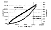
図14は、アンモニア流量と圧力損失または交換熱量との関係を示すグラフである。凝縮水が0℃から5℃まで昇温するのに必要な交換熱量を求めた後、配管径が0.15mで一定かつパス数が9で一定の条件下で、アンモニア流量を変えた場合のアンモニア側の交換熱量を計算した。アンモニア側の交換熱量が、凝縮水の昇温に必要な交換熱量以上にならないと、凝縮水が5℃まで昇温しない。そこで、アンモニア側の交換熱量が凝縮水の昇温に必要な交換熱量以上となるアンモニア流量を求めた。
図14から明らかなように、アンモニア流量が多くなるほど、圧力損失は増加する傾向にある。また、凝縮水の発生量から凝縮水が熱交換可能な最大熱量を、図中の凝縮水最大交換熱量として求めた。アンモニア側の交換熱量が、凝縮水最大交換熱量未満であると、凝縮水の冷熱が一部無駄になる。このため、アンモニアの交換熱量が凝縮水最大交換熱量以上となるように、アンモニア流量は800kg/h程度以上であることが好ましい。
図15は、アンモニア流量と圧力損失または交換熱量との関係を示すグラフである。計算条件は図14の場合とほぼ同じであるが、配管径が0.05mである点で異なる。配管径が0.05mの場合には、圧力損失を10kPa以下に抑えつつ、アンモニア側の交換熱量を凝縮水最大交換熱量以上とすることができないため、パス数を増加させる必要がある。
(その他の実施形態)
本発明は上記実施形態に限定されるものではなく、その趣旨を逸脱しない限りにおいて上記実施形態の要素を適宜組み合わせ、または種々の変更を加えることが可能である。特に、今回開示された実施形態において、明示的に開示されていない事項、例えば、動作条件や測定条件、各種パラメータ、構成物の寸法、重量、体積などは、当業者が通常実施する範囲を逸脱するものではなく、通常の当業者であれば、容易に想定することが可能な値を採用している。
本発明は上記実施形態に限定されるものではなく、その趣旨を逸脱しない限りにおいて上記実施形態の要素を適宜組み合わせ、または種々の変更を加えることが可能である。特に、今回開示された実施形態において、明示的に開示されていない事項、例えば、動作条件や測定条件、各種パラメータ、構成物の寸法、重量、体積などは、当業者が通常実施する範囲を逸脱するものではなく、通常の当業者であれば、容易に想定することが可能な値を採用している。
例えば、上記実施形態では、貯留タンク60として、伝熱管11の表面で発生した凝縮水をガス配管50へ流下させる前に回収する第1貯留タンク60Aに加えて、ガス配管50へ流下させた凝縮水を再び回収する第2貯留タンク60B、60Cをさらに設ける構成とした。しかしながら、貯留タンク60として、第1貯留タンクおよび第2貯留タンクのうちいずれか一方のみを設けることとしてもよいし、第2貯留タンクの数は2つに限定されず、1つでも3つ以上であってもよい。なお、第1貯留タンクを設けずに第2貯留タンクのみを設ける形態としては、例えば、中間媒体加温器10の伝熱管11の鉛直下方にガス配管50を配置し、伝熱管11から直接ガス配管50に滴下した凝縮水を第2貯留タンクで回収することが考えられる。
また、上記実施形態では、ガス配管50内の天然ガスNGを加温する気化ガス加温器30を設けたが、凝縮水による加温のみでガス配管50内の天然ガスNGが目標温度に達するのであれば、気化ガス加温器30を省略してもよい。また、気化ガス加温器30は空温式のものに限定されず、空気以外の熱媒体を用いたものやヒーターを採用することもできる。さらに、気化ガス加温器30の配設位置は、図1に示した位置に限定されず、ガス配管50の適宜の位置とすることが可能である。
また、凝縮水を回収し、ガス配管50へ流下させる具体構成は適宜変更が可能である。例えば、貯留タンク60に回収部62を設けず、全体を貯留部61としてもよいし、貯留タンク60に凝縮水を導くための案内部材を別途設けてもよい。また、樋部材70のような別部材により、凝縮水を貯留タンク60からガス配管50へ流下させるのみならず、傾斜部73のような部材を貯留タンク60に一体形成してもよい。さらに、貯留タンク60の堰64aの鉛直下方にガス配管50を配置し、貯留タンク60から流出した凝縮水が滴下することでガス配管50に至る形態も、本発明における「ガス配管へ流下させる」という概念に含まれる。
また、上記実施形態においては、中間媒体加温器10は液状の中間媒体を気化させるものとしたが、中間媒体加温器10で液状の中間媒体を気化させることは必須ではない。例えば、ブライン等の不凍液を中間媒体として用いた場合には、中間媒体加温器10は液状の中間媒体を相変化させずに、単に昇温させるだけでもよい。
また、上記実施形態においては、中間媒体加温器10で発生した凝縮水を利用することについてのみ説明してきたが、気化ガス加温器30で発生した凝縮水を同様に有効活用してもよい。
本出願は2014年7月2日出願の日本特許出願(特願2014-136598)および2015年2月2日出願の日本特許出願(特願2015-018182)に基づくものであり、その内容はここに参照として取り込まれる。
1 液化ガス気化装置
10 中間媒体加温器
11 伝熱管
20 液化ガス蒸発器
30 気化ガス加温器
50 ガス配管
60 貯留タンク
60A 第1貯留タンク
60B 第2貯留タンク
61 貯留部
64 壁体
64a 堰
65 壁体
66 壁体
68 仕切体
69 中間堰
70 樋部材
73 傾斜部
80 温度計
90 制御手段
100 液化ガス気化システム
101 循環配管
102 蒸発部
103 タービン
104 発電機
105 凝縮部
10 中間媒体加温器
11 伝熱管
20 液化ガス蒸発器
30 気化ガス加温器
50 ガス配管
60 貯留タンク
60A 第1貯留タンク
60B 第2貯留タンク
61 貯留部
64 壁体
64a 堰
65 壁体
66 壁体
68 仕切体
69 中間堰
70 樋部材
73 傾斜部
80 温度計
90 制御手段
100 液化ガス気化システム
101 循環配管
102 蒸発部
103 タービン
104 発電機
105 凝縮部
Claims (16)
- 加温用気体との熱交換によって、伝熱管内を流れる中間媒体を加温する中間媒体加温器と、
前記中間媒体加温器で加温された前記中間媒体との熱交換によって、液化ガスを気化させて気化ガスを生成する液化ガス蒸発器と、
前記液化ガス蒸発器で生成された前記気化ガスが流れるガス配管と、
を備え、
前記加温用気体が水蒸気を含み、前記伝熱管の表面温度が前記加温用気体の露点よりも低くなっていることで、前記伝熱管の表面で凝縮水が発生しており、
前記凝縮水を、前記伝熱管よりも低い位置に配置された貯留タンクの貯留部に貯留した状態で、前記凝縮水よりも高温の大気との熱交換によって加温した後、前記貯留タンクよりも低い位置にある前記ガス配管へ自重により流下させることで、前記ガス配管内の前記気化ガスを加温することを特徴とする液化ガス気化装置。 - 前記貯留タンクとして、前記伝熱管の表面で発生した前記凝縮水を、前記ガス配管へ流下させる前に回収する第1貯留タンクが設けられている請求項1に記載の液化ガス気化装置。
- 前記貯留タンクとして、前記ガス配管へ流下させた前記凝縮水を再び回収する第2貯留タンクがさらに少なくとも1つ設けられている請求項2に記載の液化ガス気化装置。
- 前記貯留部を形成する壁体の一部は他の部分よりも高さが低い堰となっており、
前記貯留部内の前記凝縮水は、前記堰を乗り越えることで前記ガス配管へ至る請求項1に記載の液化ガス気化装置。 - 前記堰を乗り越えた前記凝縮水を前記ガス配管に案内する樋部材をさらに備える請求項4に記載の液化ガス気化装置。
- 前記ガス配管が円管であるとともに、前記樋部材は前記ガス配管へ向けて前記凝縮水を流下させる傾斜部を有しており、
前記ガス配管の軸方向と直交する断面において、前記傾斜部の先端から鉛直下方におろした直線と前記ガス配管との交点が、前記ガス配管の頂点から前記傾斜部の基端側へ周方向に45度の範囲内に位置する請求項5に記載の液化ガス気化装置。 - 前記貯留部には、前記凝縮水が前記貯留部への流入位置から前記堰に至る流路に、前記凝縮水が乗り越える必要のある中間堰が設けられている請求項4に記載の液化ガス気化装置。
- 前記貯留部には、前記凝縮水が前記貯留部への流入位置から前記堰に直接流れる場合と比べて、前記凝縮水が前記流入位置から前記堰に至るまでの流路を長くさせる仕切体が設けられている請求項4に記載の液化ガス気化装置。
- 前記ガス配管内の前記気化ガスを加温する気化ガス加温器をさらに備えた請求項1に記載の液化ガス気化装置。
- 前記気化ガス加温器よりも下流側の前記ガス配管内の前記気化ガスの温度を測定する温度計と、
前記温度計による前記気化ガスの測定値が一定となるように、前記気化ガス加温器の動作を制御する制御手段と、
をさらに備えた請求項9に記載の液化ガス気化装置。 - 前記貯留部内の前記凝縮水の平均液膜厚さt[m]、単位時間あたりに発生する前記凝縮水の量Q[m3/min]、前記貯留部の底面積S[m2]が、次式(1)を満たす請求項1~10のいずれか1項に記載の液化ガス気化装置。
S≧(2044-16.2/t)Q・・・式(1) - 請求項2に記載の液化ガス気化装置と、
前記第1貯留タンクと地中との間にわたって配設され、内部を作動媒体が流れる循環配管と、
地熱または地中熱により気化した前記作動媒体の蒸気により稼働する発電機と、
を備えた液化ガス気化システムであって、
前記循環配管は、前記第1貯留タンクに貯留されている前記凝縮水の中を通過する凝縮部を有しており、前記作動媒体の蒸気は前記凝縮部で凝縮されることを特徴とする液化ガス気化システム。 - 前記第1貯留タンクのうち少なくとも前記貯留部に対して、断熱施工がなされている請求項12に記載の液化ガス気化システム。
- 前記凝縮部のうち前記貯留部外に位置する部分の熱伝導率は、前記凝縮部のうち前記貯留部内に位置する部分の熱伝導率よりも小さい請求項12に記載の液化ガス気化システム。
- 前記第1貯留タンクが複数設けられており、
前記凝縮部は、前記複数の第1貯留タンクのすべてを複数回通過する請求項12に記載の液化ガス気化システム。 - 前記貯留部を形成する壁体の一部に、他の部分よりも高さが低い堰が設けられており、
前記凝縮部の配管径は、0.05m以上かつ前記堰の高さ以下である請求項12~15のいずれか1項に記載の液化ガス気化システム。
Applications Claiming Priority (4)
| Application Number | Priority Date | Filing Date | Title |
|---|---|---|---|
| JP2014-136598 | 2014-07-02 | ||
| JP2014136598 | 2014-07-02 | ||
| JP2015-018182 | 2015-02-02 | ||
| JP2015018182A JP6407744B2 (ja) | 2014-07-02 | 2015-02-02 | 液化ガス気化装置および液化ガス気化システム |
Publications (1)
| Publication Number | Publication Date |
|---|---|
| WO2016002592A1 true WO2016002592A1 (ja) | 2016-01-07 |
Family
ID=55019135
Family Applications (1)
| Application Number | Title | Priority Date | Filing Date |
|---|---|---|---|
| PCT/JP2015/068108 Ceased WO2016002592A1 (ja) | 2014-07-02 | 2015-06-23 | 液化ガス気化装置および液化ガス気化システム |
Country Status (2)
| Country | Link |
|---|---|
| JP (1) | JP6407744B2 (ja) |
| WO (1) | WO2016002592A1 (ja) |
Cited By (1)
| Publication number | Priority date | Publication date | Assignee | Title |
|---|---|---|---|---|
| CN117404611A (zh) * | 2023-12-14 | 2024-01-16 | 唐山冀东油田新能源开发有限公司 | 一种管道用液化气检测仪及其检测方法 |
Families Citing this family (2)
| Publication number | Priority date | Publication date | Assignee | Title |
|---|---|---|---|---|
| JP7209965B2 (ja) * | 2019-02-27 | 2023-01-23 | 東北電力株式会社 | ガス気化システム |
| JP2021188638A (ja) * | 2020-05-27 | 2021-12-13 | 株式会社神戸製鋼所 | 中間媒体式熱交換器 |
Citations (4)
| Publication number | Priority date | Publication date | Assignee | Title |
|---|---|---|---|---|
| JPS5380846A (en) * | 1976-12-27 | 1978-07-17 | Mitsui Eng & Shipbuild Co Ltd | Utilizing device for cooling heat in liquefed gas evaporator |
| JPS6117799A (ja) * | 1984-07-02 | 1986-01-25 | Kawasaki Heavy Ind Ltd | 液化天然ガスより圧縮天然ガスを製造する方法 |
| JPH0495699A (ja) * | 1990-08-10 | 1992-03-27 | Tokyo Gas Co Ltd | 低温液化ガスの気化装置 |
| JPH06185696A (ja) * | 1992-12-21 | 1994-07-08 | Tokyo Gas Co Ltd | 低温液化ガスの気化装置 |
-
2015
- 2015-02-02 JP JP2015018182A patent/JP6407744B2/ja not_active Expired - Fee Related
- 2015-06-23 WO PCT/JP2015/068108 patent/WO2016002592A1/ja not_active Ceased
Patent Citations (4)
| Publication number | Priority date | Publication date | Assignee | Title |
|---|---|---|---|---|
| JPS5380846A (en) * | 1976-12-27 | 1978-07-17 | Mitsui Eng & Shipbuild Co Ltd | Utilizing device for cooling heat in liquefed gas evaporator |
| JPS6117799A (ja) * | 1984-07-02 | 1986-01-25 | Kawasaki Heavy Ind Ltd | 液化天然ガスより圧縮天然ガスを製造する方法 |
| JPH0495699A (ja) * | 1990-08-10 | 1992-03-27 | Tokyo Gas Co Ltd | 低温液化ガスの気化装置 |
| JPH06185696A (ja) * | 1992-12-21 | 1994-07-08 | Tokyo Gas Co Ltd | 低温液化ガスの気化装置 |
Cited By (2)
| Publication number | Priority date | Publication date | Assignee | Title |
|---|---|---|---|---|
| CN117404611A (zh) * | 2023-12-14 | 2024-01-16 | 唐山冀东油田新能源开发有限公司 | 一种管道用液化气检测仪及其检测方法 |
| CN117404611B (zh) * | 2023-12-14 | 2024-02-13 | 唐山冀东油田新能源开发有限公司 | 一种管道用液化气检测仪及其检测方法 |
Also Published As
| Publication number | Publication date |
|---|---|
| JP6407744B2 (ja) | 2018-10-17 |
| JP2016027272A (ja) | 2016-02-18 |
Similar Documents
| Publication | Publication Date | Title |
|---|---|---|
| US20070289303A1 (en) | Heat transfer for ocean thermal energy conversion | |
| US20140060046A1 (en) | Thermal Storage System and Power Generation System Including the Same | |
| JP6268714B2 (ja) | 地熱発電システム | |
| CN102428327A (zh) | 燃气热泵式热水器 | |
| JP2014202149A (ja) | 地熱発電システム | |
| US10648678B2 (en) | Building-integrated solar energy system | |
| JP6198452B2 (ja) | 中間媒体式気化器 | |
| JP6407744B2 (ja) | 液化ガス気化装置および液化ガス気化システム | |
| US8572967B1 (en) | High efficiency OTEC system | |
| JP2013032836A (ja) | 低温液化ガス気化装置及び低温液化ガス気化方法 | |
| JP5580225B2 (ja) | 真空式温水器 | |
| KR101516913B1 (ko) | 액화천연가스 기화장치 | |
| CN105091411A (zh) | 一种制冷制热两用热管型地埋管换热器 | |
| KR102522339B1 (ko) | 액화 천연 가스 기화기 및 냉수 공급 방법 | |
| JP5653861B2 (ja) | 温水器 | |
| KR20140053509A (ko) | 풍력발전기의 가열 공기를 이용한 해수 온도차 발전 시스템 | |
| JP2017227130A (ja) | 独立配置型地熱回収装置及びこれを備えた地熱発電システム | |
| JP7124263B2 (ja) | 採放熱管およびそれを用いた地中熱ヒートポンプ | |
| JP3987245B2 (ja) | 冷熱発生機能付き液化ガス気化設備 | |
| JP6666703B2 (ja) | 熱交換器 | |
| Ito et al. | Studies of a thermosyphon system with a heat source near the top and heat sink at the bottom | |
| JP5580224B2 (ja) | 真空式温水器 | |
| JP2007247797A (ja) | Lngベーパライザ | |
| CN114370663B (zh) | 电蓄热装置及其控制方法 | |
| WO2010146202A1 (es) | Procedimiento de refrigeración por tiro natural de una planta de concentración solar |
Legal Events
| Date | Code | Title | Description |
|---|---|---|---|
| 121 | Ep: the epo has been informed by wipo that ep was designated in this application |
Ref document number: 15814086 Country of ref document: EP Kind code of ref document: A1 |
|
| NENP | Non-entry into the national phase |
Ref country code: DE |
|
| 122 | Ep: pct application non-entry in european phase |
Ref document number: 15814086 Country of ref document: EP Kind code of ref document: A1 |