WO2016002319A1 - 電力変換装置 - Google Patents
電力変換装置 Download PDFInfo
- Publication number
- WO2016002319A1 WO2016002319A1 PCT/JP2015/062065 JP2015062065W WO2016002319A1 WO 2016002319 A1 WO2016002319 A1 WO 2016002319A1 JP 2015062065 W JP2015062065 W JP 2015062065W WO 2016002319 A1 WO2016002319 A1 WO 2016002319A1
- Authority
- WO
- WIPO (PCT)
- Prior art keywords
- power
- short
- bypass unit
- bypass
- energy storage
- Prior art date
- Legal status (The legal status is an assumption and is not a legal conclusion. Google has not performed a legal analysis and makes no representation as to the accuracy of the status listed.)
- Ceased
Links
Images


Classifications
-
- H—ELECTRICITY
- H02—GENERATION; CONVERSION OR DISTRIBUTION OF ELECTRIC POWER
- H02M—APPARATUS FOR CONVERSION BETWEEN AC AND AC, BETWEEN AC AND DC, OR BETWEEN DC AND DC, AND FOR USE WITH MAINS OR SIMILAR POWER SUPPLY SYSTEMS; CONVERSION OF DC OR AC INPUT POWER INTO SURGE OUTPUT POWER; CONTROL OR REGULATION THEREOF
- H02M1/00—Details of apparatus for conversion
- H02M1/32—Means for protecting converters other than automatic disconnection
-
- H—ELECTRICITY
- H02—GENERATION; CONVERSION OR DISTRIBUTION OF ELECTRIC POWER
- H02M—APPARATUS FOR CONVERSION BETWEEN AC AND AC, BETWEEN AC AND DC, OR BETWEEN DC AND DC, AND FOR USE WITH MAINS OR SIMILAR POWER SUPPLY SYSTEMS; CONVERSION OF DC OR AC INPUT POWER INTO SURGE OUTPUT POWER; CONTROL OR REGULATION THEREOF
- H02M3/00—Conversion of DC power input into DC power output
- H02M3/02—Conversion of DC power input into DC power output without intermediate conversion into AC
- H02M3/04—Conversion of DC power input into DC power output without intermediate conversion into AC by static converters
- H02M3/10—Conversion of DC power input into DC power output without intermediate conversion into AC by static converters using discharge tubes with control electrode or semiconductor devices with control electrode
- H02M3/145—Conversion of DC power input into DC power output without intermediate conversion into AC by static converters using discharge tubes with control electrode or semiconductor devices with control electrode using devices of a triode or transistor type requiring continuous application of a control signal
- H02M3/155—Conversion of DC power input into DC power output without intermediate conversion into AC by static converters using discharge tubes with control electrode or semiconductor devices with control electrode using devices of a triode or transistor type requiring continuous application of a control signal using semiconductor devices only
- H02M3/156—Conversion of DC power input into DC power output without intermediate conversion into AC by static converters using discharge tubes with control electrode or semiconductor devices with control electrode using devices of a triode or transistor type requiring continuous application of a control signal using semiconductor devices only with automatic control of output voltage or current, e.g. switching regulators
- H02M3/158—Conversion of DC power input into DC power output without intermediate conversion into AC by static converters using discharge tubes with control electrode or semiconductor devices with control electrode using devices of a triode or transistor type requiring continuous application of a control signal using semiconductor devices only with automatic control of output voltage or current, e.g. switching regulators including plural semiconductor devices as final control devices for a single load
-
- H—ELECTRICITY
- H02—GENERATION; CONVERSION OR DISTRIBUTION OF ELECTRIC POWER
- H02M—APPARATUS FOR CONVERSION BETWEEN AC AND AC, BETWEEN AC AND DC, OR BETWEEN DC AND DC, AND FOR USE WITH MAINS OR SIMILAR POWER SUPPLY SYSTEMS; CONVERSION OF DC OR AC INPUT POWER INTO SURGE OUTPUT POWER; CONTROL OR REGULATION THEREOF
- H02M7/00—Conversion of AC power input into DC power output; Conversion of DC power input into AC power output
- H02M7/42—Conversion of DC power input into AC power output without possibility of reversal
- H02M7/44—Conversion of DC power input into AC power output without possibility of reversal by static converters
- H02M7/48—Conversion of DC power input into AC power output without possibility of reversal by static converters using discharge tubes with control electrode or semiconductor devices with control electrode
- H02M7/483—Converters with outputs that each can have more than two voltages levels
- H02M7/4835—Converters with outputs that each can have more than two voltages levels comprising two or more cells, each including a switchable capacitor, the capacitors having a nominal charge voltage which corresponds to a given fraction of the input voltage, and the capacitors being selectively connected in series to determine the instantaneous output voltage
-
- H—ELECTRICITY
- H02—GENERATION; CONVERSION OR DISTRIBUTION OF ELECTRIC POWER
- H02M—APPARATUS FOR CONVERSION BETWEEN AC AND AC, BETWEEN AC AND DC, OR BETWEEN DC AND DC, AND FOR USE WITH MAINS OR SIMILAR POWER SUPPLY SYSTEMS; CONVERSION OF DC OR AC INPUT POWER INTO SURGE OUTPUT POWER; CONTROL OR REGULATION THEREOF
- H02M1/00—Details of apparatus for conversion
- H02M1/0003—Details of control, feedback or regulation circuits
- H02M1/0006—Arrangements for supplying an adequate voltage to the control circuit of converters
-
- H—ELECTRICITY
- H02—GENERATION; CONVERSION OR DISTRIBUTION OF ELECTRIC POWER
- H02M—APPARATUS FOR CONVERSION BETWEEN AC AND AC, BETWEEN AC AND DC, OR BETWEEN DC AND DC, AND FOR USE WITH MAINS OR SIMILAR POWER SUPPLY SYSTEMS; CONVERSION OF DC OR AC INPUT POWER INTO SURGE OUTPUT POWER; CONTROL OR REGULATION THEREOF
- H02M1/00—Details of apparatus for conversion
- H02M1/32—Means for protecting converters other than automatic disconnection
- H02M1/325—Means for protecting converters other than automatic disconnection with means for allowing continuous operation despite a fault, i.e. fault tolerant converters
Definitions
- the present invention relates to a power conversion device including a plurality of cell converters connected in series with each other, and particularly to a technique for bypassing the cell converter when the cell converter fails.
- a modular multi-level converter connects the output terminals of a cell converter composed of a switching element such as an IGBT, which can be controlled to be turned on and off, and a DC capacitor in series with each other.
- This is a circuit system that can output and is a circuit system that is expected to be applied to a direct current power transmission system (HVDC), a reactive power compensator (STATCOM), and the like.
- HVDC direct current power transmission system
- STATCOM reactive power compensator
- the MMC is configured by connecting a plurality of cell converters in series (cascade).
- Each cell converter includes a main circuit composed of a switching element and a DC capacitor, an external terminal for cascading with other cell converters, bypass means connected to both ends of the external terminal, and a DC capacitor for the main circuit.
- a self-powered power source that obtains energy from and drives the bypass means and the like.
- the bypass means is a normally-on short-circuit switch that can short-circuit the output of the cell converter when the cell converter fails, and the output of the failed cell converter is short-circuited by the short-circuit switch. It is also possible to continue operation as a system even if the device breaks down.
- a normally-on short-circuit switch 209 is connected in parallel to the output terminal as a bypass means for each cell converter 105.
- the self-power supply 208 is connected in parallel with the DC capacitor 203 and supplies drive power for the short-circuit switch 209 from the self-power supply 208.
- the driving power is not supplied from the self-supplied power source 208. Therefore, the output of the cell converter 105 is short-circuited when the short-circuit switch 209 is turned on, and one cell converter 105 fails. Also, it becomes possible to continue operation as a power conversion device.
- Japanese Patent No. 5378274 (refer to claim 11, paragraphs 0100 to 0102, FIGS. 1 and 2 etc.)
- the present invention has been made to solve the above-described problems, and an object of the present invention is to provide a power conversion device that can always continue to operate safely as a power conversion device even if a cell converter fails.
- a power conversion device is a power conversion device including a plurality of cell converters connected in series to each other, and each cell converter includes a main circuit including a switching element and a capacitor, A pair of external terminals for deriving the circuit to the outside, a bypass part capable of short-circuiting between the pair of external terminals, and a gate that performs power conversion between the pair of external terminals and the capacitor by controlling on / off of the switching element
- the power conversion device including the driving device and the self-feeding device that inputs the voltage of the capacitor to feed the gate driving device, An energy storage unit that inputs and stores the voltage of the self-power feeding device, and a bypass unit drive that short-circuits the bypass unit with the electric power stored in the energy storage unit when the voltage of the self-power feeding device falls below a preset lower limit value It is equipped with a device.
- the power conversion device stores energy when the voltage of the self-power feeding device is input and stored, and when the voltage of the self-power feeding device is less than a preset lower limit value. Since the bypass unit drive device that short-circuits the bypass unit with the power stored in the unit is provided, the above-mentioned voltage lower limit value that is a threshold value for the short-circuit operation is appropriately set, so that even if the cell converter fails, Thus, a reliable short-circuit protection operation is realized, and the power conversion device can be continuously operated safely.
- FIG. 1 is a diagram showing a configuration of a power conversion device according to Embodiment 1 of the present invention.
- the power conversion device includes cell converters 100a, 100b, 100c,... Connected in series (cascade) to each other.
- the internal configuration of the cell converter 100a will be described with the same as the cell converter 100a.
- Switching elements 1a and 1b that can be controlled on and off are connected in series to each other, and a capacitor 2 is connected to this to constitute a main circuit 50.
- a diode is connected in antiparallel to each switching element 1a, 1b.
- the main circuit 50 is led to the outside by a pair of external terminals X1 and X2, and is connected to other cell converters 100b and 100c.
- the bypass part 4 is connected to these external terminals X1 and X2.
- a self-power feeding device 3 for inputting the voltage of the capacitor 2 of the main circuit 50 and feeding power to a gate driving device 9 and an energy storage unit 5 described later is provided.
- the self-feeding device 3 is usually constituted by a DC / DC converter that converts the high voltage of the capacitor 2 that fluctuates by the operation of the main circuit 50 into a constant low voltage.
- the gate driving device 9 performs on / off control of the switching elements 1a and 1b based on the power supplied from the self-feeding device 3 via the first feeding line 7 to thereby establish a connection between the pair of external terminals X1 and X2 and the capacitor 2.
- the power conversion is performed, and the voltage of the capacitor 2 or the zero voltage is output between the external terminals X1 and X2.
- the energy storage unit 5 inputs the voltage of the self-feeding device 3 through the first feeding line 7 and stores it. It is desirable to insert a diode 10 for blocking a current flowing backward in the feeding direction into the portion connected to the energy storage unit 5 of the first feeding line 7 for the reason described later.
- the energy storage part 5 storage batteries, such as a capacitor
- the former capacitor it is generally cheaper than a storage battery and is excellent in variation in capacity, so that there is an advantage that it is easy to select an appropriate capacity.
- the latter storage battery there is an advantage that the amount of spontaneous discharge is small and the electric power from the self-power feeding device 3 can be stored more efficiently.
- the bypass unit driving device 6 inputs the electric power stored in the energy storage unit 5 through the second power supply line 8, and the lower limit value set in advance by the voltage of the self-power feeding device 3 as described later with reference to FIG. When it becomes less than, the bypass unit 4 is short-circuited by the accumulated electric power.
- Opening failure of the switching element 1a In this case, since the connection line of the capacitor 2 is in an open state, the voltage of the capacitor 2 decreases and the output voltage of the self-feeding device 3 decreases.
- Opening failure of the switching element 1b In this case, there is only an operation mode in which the voltage of the capacitor 2 is increased, the capacitor 2 is finally opened due to an overvoltage, and the voltage of the capacitor 2 is lowered. This leads to a decrease in the output voltage.
- Opening failure of the capacitor 2 In this case, the voltage of the capacitor 2 is lowered and the output voltage of the self-feeding device 3 is lowered.
- the output voltage of the self-power feeding device 3 is greatly reduced or zero, and power feeding from the self-power feeding device 3 cannot be expected.
- the bypass part 4 can be short-circuited reliably with the remaining amount. As described above, if the diode 10 is inserted in the portion connected to the energy storage unit 5 of the first power supply line 7, the energy storage unit 5 even if the output terminal of the self-power feeding device 3 is short-circuited. The energy stored in is not reliably released to the failed self-feeding device 3 side, but is reliably utilized for the short-circuit operation of the bypass unit 4.
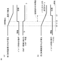
- FIG. 2A shows the case of the present invention.
- the remaining amount of energy stored in the energy storage unit 5 is reduced from the previous full level to a level obtained by reducing the energy spent for one short-circuit operation as shown in the lower characteristic curve. It will be.
- bypass unit 4 since the bypass unit 4 needs to hold the short-circuit operation until the self-power feeding device 3 returns from the failure and receives a reopening command, the bypass unit 4 holds the short-circuit operation after the short-circuit operation. It is necessary to provide a latch function.
- bypass part 4 is comprised with a vacuum switch.
- a vacuum switch opens and closes a contact in a vacuumed valve. Since the distance required for insulation can be shortened, the vacuum switch can be miniaturized and a high-speed short-circuit operation can be realized.
- the driving force a system using a permanent magnet attracting force or a spring is widely known. However, a strong driving force by the bypass drive unit 6 is required for these operations.
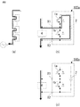
- FIG. 3 is a diagram for explaining the operation when a vacuum switch is applied as the bypass unit 4.
- FIG. 3A to FIG. 3C are diagrams for explaining the principle of the short-circuit operation, the holding of the short-circuit operation state, and the open operation, respectively.
- this type of vacuum switch is provided with a latch function using the magnetic attractive force of a permanent magnet. After a short-circuit operation, the current supply to the coil is cut off due to a failure of the self-feeding device 3. Moreover, the bypass part 4 can hold
- a spring-type mechanical switch can be used as the bypass portion 4.
- the mechanical switch is large in size and short-circuiting operation is slow compared with the vacuum switch, but is inexpensive and easily available.
- a strong driving force by the bypass unit driving device 6 is required.
- a driving force a system mainly using a spring is widely known, but a power supply is required for these operations. Since the latch mechanism is provided to mechanically latch after the short circuit operation, the short circuit operation can be continued unless the latch is released manually.
- the energy storage unit 5 that inputs and stores the voltage of the self-power feeding device 3 and the voltage of the self-power feeding device 3 are less than a preset lower limit value. Since the bypass unit driving device 6 that short-circuits the bypass unit 4 with the electric power stored in the energy storage unit 5 is provided, the cell voltage can be appropriately set by setting the above-described voltage lower limit value that is a threshold for the short-circuit operation. Even if the converter 100 breaks down, a quick and reliable short-circuit protection operation is realized, and it is possible to always continue to operate safely as a power converter.
- the diode 10 for blocking the current flowing backward in the feeding direction is inserted into the first feeding line 7 that connects the self-feeding device 3 and the energy storage unit 5, even if the output terminal of the self-feeding device 3 is in a short-circuited state. Even in this case, the energy stored in the energy storage unit 5 is reliably utilized for the short-circuit operation of the bypass unit 4 without being released to the failed self-power feeding device 3 side.
- bypass unit has a latch function for holding the short-circuit operation after the short-circuit operation, even if the power supply to the bypass-unit drive device 6 is cut off due to the failure of the self-power supply device 3 after the short-circuit operation, the bypass unit The part 4 can maintain a short circuit state, and can continue the operation as a power converter without any trouble.
- Embodiment 2 FIG. In the first embodiment, as the bypass portion 4, the one that is latched by using the magnetic attractive force of the permanent magnet is exemplified, but problems and solutions in that case will be described in the second embodiment.
- FIG. 4 is a timing chart showing the operation timing of the bypass unit 4 in this case.
- energy is used for driving the short-circuit operation of the bypass unit 4
- the remaining energy of the energy storage unit 5 is almost zero. Even if an operation of passing a current in the reverse direction to the coil during the short-circuit operation is mistakenly performed, there is no energy for actually driving the bypass unit 4, so that the opening operation of the bypass unit 4 is reliably prevented.
- the power conversion device is the minimum that can perform the short-circuit operation of the bypass unit 4 by the bypass unit drive device 6 once as the storage capacity that can be stored in the energy storage unit 5. Therefore, the opening operation of the bypass unit 4 due to an erroneous operation after the short circuit operation is reliably prevented.
- Embodiment 3 FIG.
- the bypass unit 4 of the cell converter 100 is quickly and surely short-circuited so that the operation can always be continued safely.
- the power converter that can be used has been described.
- the third embodiment is not a failure of the cell converter 100, and thus is normal as a power converter, but the power converter is not properly operated due to an accident outside the power converter such as a system short circuit accident. It is assumed that the output voltage of the self-feeding device 3 of all the cell converters 100 is stopped and all the bypass units 4 are short-circuited.
- the third embodiment has been created to meet the expectation.
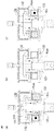
- FIG. 5 illustrates a phenomenon related to the charging operation of the capacitor 2, and during the operation of the power conversion device, as shown in FIGS.
- the current flowing in from the terminal X1 is supplied to the capacitor 2 via the upper diode and charges the capacitor 2.
- the self-power feeding device 3 is operable by being supplied with a voltage from the capacitor 2.
- the bypass unit 4 since the bypass unit 4 is driven by the power stored in the energy storage unit 5, the power conversion device can be restarted. It becomes possible.
- the energy storage unit 5 at least the short-circuit operation of the bypass unit 4 is executed once, and further, the capacity necessary for opening the bypass unit 4 after the short-circuit operation. It is necessary to have something.
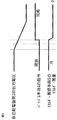
- FIG. 6 is a timing chart showing the operation timing of the bypass unit 4 of the power conversion device according to Embodiment 3 of the present invention.
- the bypass unit driving device 6 immediately considers that a failure has been detected and stores it in the energy storage unit 5.
- the bypass unit 4 is short-circuited by the accumulated power (time t2).
- bypass unit driving device 6 receives an opening command at time t4, it is stored in the energy storage unit 5 as shown in FIG.
- the latch function of the bypass unit 4 is immediately released by the remaining power and the bypass unit 4 is opened (time t5).
- the power conversion device itself is not abnormal and explained the re-operation measure when it stops due to the occurrence of an external accident, but the cell converter bypass section short-circuited due to the failure of the cell converter,
- the present invention can be similarly applied to measures for restarting the cell converter when the cell converter recovers from a failure state.
- the bypass unit driving device 6 of the power conversion device when the bypass unit driving device 6 of the power conversion device according to the third embodiment of the present invention receives the opening command after the bypass unit 4 is short-circuited, the power stored in the energy storage unit 5 is used. Since the latch function of the bypass unit 4 is released and the bypass unit 4 is opened, the cell converter 100 and the power conversion device can be quickly restarted by appropriately setting the capacity of the energy storage unit 5. Realize.
Landscapes
- Engineering & Computer Science (AREA)
- Power Engineering (AREA)
- Dc-Dc Converters (AREA)
- Power Conversion In General (AREA)
- Inverter Devices (AREA)
Abstract
Description
セル変換器105が停止した場合、自給電源208から駆動電力が供給されなくなるため、短絡スイッチ209が自己オンすることでセル変換器105の出力が短絡され、セル変換器105が1台故障しても電力変換装置として運転継続させることが可能となる。
更に、自給電源208からの電圧が短絡動作可能なレベル付近で上下に変動することで短絡スイッチ209の短絡動作がチャタリングを起こして不安定となる恐れがあり、これらに伴い、電力変換装置の運転が一時的に継続出来ない可能性が生じる。
自己給電装置の電圧を入力して蓄電するエネルギー蓄積部、および自己給電装置の電圧が予め設定した下限値未満となったときエネルギー蓄積部に蓄積された電力によりバイパス部を短絡動作させるバイパス部駆動装置を備えたものである。
図1は、この発明の実施の形態1による電力変換装置の構成を示す図である。電力変換装置は、互いに直列に(カスケード)接続されたセル変換器100a、100b、100c・・・を備えている。以下、代表して、セル変換器100aを同100としてその内部構成について説明する。
なお、自己給電装置3としては、主回路50の動作で変動するコンデンサ2の高電圧を一定の低電圧に変換するDC/DCコンバータで構成するのが普通である。
前者のコンデンサの場合は、一般に蓄電池より安価であり、また、容量のバリエーションに優れているため、適切な容量の選択が容易という利点がある。
後者の蓄電池を採用した場合は、自然放電の量が少なく、自己給電装置3からの電力をより効率的に蓄電できるという利点がある。
1)スイッチング素子1aの開放故障:この場合、コンデンサ2の接続ラインが開放状態となるので、コンデンサ2の電圧が低下し、自己給電装置3の出力電圧低下に至る。
2)スイッチング素子1bの開放故障:この場合、コンデンサ2の電圧を増加させる動作モードしか存在しなくなり、コンデンサ2が最終的に過電圧により開放故障してコンデンサ2の電圧が低下し、自己給電装置3の出力電圧低下に至る。
3)コンデンサ2の開放故障:この場合、コンデンサ2の電圧が低下し、自己給電装置3の出力電圧低下に至る。
4)ゲート駆動装置9の故障:この場合、スイッチング素子1a、1bが動作しなくなり、それに伴い、コンデンサ2に電圧が供給されなくなり、自己給電装置3の出力電圧低下に至る。
5)自己給電装置3自体の故障:自己給電装置3の出力電圧が低下し、その結果、ゲート駆動装置9およびエネルギー蓄積部5への給電が途絶える。
上述したように、第一給電線7のエネルギー蓄積部5に接続される部分にダイオード10を挿入しておけば、たとえ、自己給電装置3の出力端が短絡状態になってもエネルギー蓄積部5に蓄積されたエネルギーは、故障した自己給電装置3側に放出されることなく、バイパス部4の短絡動作に確実に活用されるわけである。
図2(a)は、本願発明の場合で、時刻t0でセル変換器100内で故障が発生すると、これに伴い、自己給電装置3の出力電圧が低下を始める。この出力電圧が時刻t1で設定下限値に達すると直ちにバイパス部駆動装置6が動作してバイパス部4は、時刻t2で速やかに短絡状態となる。
真空スイッチは、真空状態になったバルブの中で接点を開閉するものであり、絶縁に必要な距離を短く出来るので小型化が可能で、かつ高速な短絡動作を実現できる。駆動力は、主に、永久磁石の吸引力やばねを用いる方式が広く知られているが、それらの動作にはバイパス部駆動装置6による強力な駆動力が必要となる。
この段階では、中心軸の周囲に配置された遮断ばねと接圧ばね(図示せず)はいずれも蓄勢された状態となっており、次の開放動作に備える。
駆動力は、主にばねを用いる方式が広く知られているが、それらの動作には電源の供給が必要である。ラッチ機構を設けることで短絡動作後には機械的にラッチされるので、人力でラッチを解除しなければ短絡動作を継続することが可能である。
先の実施の形態1では、バイパス部4として、永久磁石の磁気吸引力を利用してラッチさせるものを例示したが、その場合の課題と解決策について、この実施の形態2で説明する。
バイパス部4のラッチ機能が機械的ではない、例えば、永久磁石の磁気吸引力を利用した方式である場合、先の図3(c)に示すように、誤ってコイルに短絡動作とは逆方向の電流を与えるとバイパス部4が開放動作を行ってしまい、電力変換装置として運転継続が出来なくなってしまう。
図4は、この場合の、バイパス部4の動作タイミングを示すタイミングチャートで、バイパス部4の短絡動作駆動用にエネルギーを使用するとエネルギー蓄積部5のエネルギー残量がほぼ零になっており、たとえ、誤ってコイルに短絡動作時とは逆方向の電流を流す操作がなされたとしても、実際にバイパス部4を駆動するエネルギーが存在しないので、バイパス部4の開放動作が確実に防止される。
先の実施の形態1および2では、いずれかのセル変換器100内で故障が発生したとき当該セル変換器100のバイパス部4を迅速確実に短絡動作させることで、常に安全に運転の継続が可能となる電力変換装置について説明した。
これに対し、この実施の形態3は、セル変換器100の故障ではなく、従って、電力変換装置としては正常であるが、系統短絡事故等、電力変換装置の外部における事故により、電力変換装置が停止しすべてのセル変換器100の自己給電装置3の出力電圧が低下して全バイパス部4が短絡動作した場合を想定したものである。
この結果、バイパス部にノーマリーオンの短絡スイッチを使用する従来の場合は、たとえ、外部事故が除去され系統が回復しても、バイパス部を外部の何らかの動力源により開放操作しない限り、電力変換装置を再稼働させることが出来ない。
図6において、時刻t0で電力変換装置が停止し、時刻t1で自己給電装置3の出力電圧が設定下限値まで低下すると、バイパス部駆動装置6は、故障検出とみなして直ちにエネルギー蓄積部5に蓄積された電力によりバイパス部4を短絡動作させる(時刻t2)。
Claims (9)
- 互いに直列に接続された複数台のセル変換器からなる電力変換装置であって、
前記各セル変換器は、スイッチング素子とコンデンサとから構成された主回路、この主回路を外部に導出するための一対の外部端子、この一対の外部端子の間を短絡可能なバイパス部、前記スイッチング素子をオンオフ制御することにより前記一対の外部端子と前記コンデンサとの間で電力変換を行うゲート駆動装置、および前記コンデンサの電圧を入力して前記ゲート駆動装置に給電する自己給電装置を備えた電力変換装置において、
前記自己給電装置の電圧を入力して蓄電するエネルギー蓄積部、および前記自己給電装置の電圧が予め設定した下限値未満となったとき前記エネルギー蓄積部に蓄積された電力により前記バイパス部を短絡動作させるバイパス部駆動装置を備えた電力変換装置。 - 前記自己給電装置と前記エネルギー蓄積部とを接続する給電線に、給電方向に逆行する電流を阻止するダイオードを挿入した請求項1記載の電力変換装置。
- 前記バイパス部は、前記短絡動作後、当該短絡動作を保持するラッチ機能を備えた請求項1または請求項2に記載の電力変換装置。
- 前記バイパス部は、前記ラッチ機能として、永久磁石の磁気吸引力を利用したものを採用した真空スイッチである請求項3記載の電力変換装置。
- 前記バイパス部は、前記ラッチ機能として、その解除が人力操作でのみ可能なものを採用した機械スイッチである請求項3記載の電力変換装置。
- 前記エネルギー蓄積部に蓄積可能な蓄電容量として、前記バイパス部駆動装置による前記バイパス部の短絡動作を1回実行可能な最小限の容量に設定する請求項1から請求項5のいずれか1項に記載の電力変換装置。
- 前記バイパス部駆動装置は、前記バイパス部を短絡動作させた後開放指令を受けたとき、前記エネルギー蓄積部に蓄積された電力により前記ラッチ機能を解除するとともに前記バイパス部を開放動作させるようにした請求項3または請求項4に記載の電力変換装置。
- 前記エネルギー蓄積部は、コンデンサである請求項1から請求項7のいずれか1項に記載の電力変換装置。
- 前記エネルギー蓄積部は、蓄電池である請求項1から請求項7のいずれか1項に記載の電力変換装置。
Priority Applications (3)
| Application Number | Priority Date | Filing Date | Title |
|---|---|---|---|
| US15/311,953 US9866120B2 (en) | 2014-06-30 | 2015-04-21 | Power conversion device |
| EP15815326.2A EP3163729B2 (en) | 2014-06-30 | 2015-04-21 | Power conversion device |
| JP2016531161A JP6366711B2 (ja) | 2014-06-30 | 2015-04-21 | 電力変換装置 |
Applications Claiming Priority (2)
| Application Number | Priority Date | Filing Date | Title |
|---|---|---|---|
| JP2014-133972 | 2014-06-30 | ||
| JP2014133972 | 2014-06-30 |
Publications (1)
| Publication Number | Publication Date |
|---|---|
| WO2016002319A1 true WO2016002319A1 (ja) | 2016-01-07 |
Family
ID=55018877
Family Applications (1)
| Application Number | Title | Priority Date | Filing Date |
|---|---|---|---|
| PCT/JP2015/062065 Ceased WO2016002319A1 (ja) | 2014-06-30 | 2015-04-21 | 電力変換装置 |
Country Status (4)
| Country | Link |
|---|---|
| US (1) | US9866120B2 (ja) |
| EP (1) | EP3163729B2 (ja) |
| JP (1) | JP6366711B2 (ja) |
| WO (1) | WO2016002319A1 (ja) |
Cited By (9)
| Publication number | Priority date | Publication date | Assignee | Title |
|---|---|---|---|---|
| EP3352357A1 (en) * | 2017-01-23 | 2018-07-25 | XJ Group Corporation | Fault protection method and device for sub-modules of modular multilevel converter |
| WO2018193606A1 (ja) * | 2017-04-21 | 2018-10-25 | 東芝三菱電機産業システム株式会社 | 電力変換装置 |
| WO2018211658A1 (ja) | 2017-05-18 | 2018-11-22 | 三菱電機株式会社 | 無効電力補償装置およびその制御方法 |
| WO2019221160A1 (ja) * | 2018-05-17 | 2019-11-21 | 三菱電機株式会社 | 電力変換装置 |
| WO2020044454A1 (ja) * | 2018-08-29 | 2020-03-05 | 東芝三菱電機産業システム株式会社 | 電力変換装置 |
| KR102177141B1 (ko) * | 2019-08-21 | 2020-11-10 | 효성중공업 주식회사 | 바이패스 스위치를 구비한 전력용 컨버터의 서브모듈 |
| WO2021034152A1 (ko) * | 2019-08-21 | 2021-02-25 | 효성중공업 주식회사 | 바이패스 스위치를 구비한 전력용 컨버터의 서브모듈 |
| JP2021048726A (ja) * | 2019-09-19 | 2021-03-25 | 富士電機株式会社 | 電力変換装置 |
| JP2021513317A (ja) * | 2018-01-31 | 2021-05-20 | 南京南瑞▲継▼保▲電気▼有限公司Nr Electric Co., Ltd | パワーモジュール冗長エネルギー取得回路およびその制御方法 |
Families Citing this family (6)
| Publication number | Priority date | Publication date | Assignee | Title |
|---|---|---|---|---|
| KR20150140966A (ko) * | 2014-06-09 | 2015-12-17 | 엘에스산전 주식회사 | 바이패스 운전 기능을 갖는 직렬형 h-브릿지 인버터 |
| EP3032680A1 (en) * | 2014-12-12 | 2016-06-15 | ABB Technology AG | Standby and charging of modular multilevel converters |
| EP3276815A4 (en) * | 2015-03-26 | 2018-11-21 | Mitsubishi Electric Corporation | Power conversion apparatus |
| EP3414819B1 (en) * | 2016-02-12 | 2020-01-08 | ABB Schweiz AG | Converter module for hvdc power station |
| US10468972B2 (en) * | 2016-05-25 | 2019-11-05 | Mitsubishi Electric Corporation | Power converter including a plurality of converter cells connected in multiple series |
| EP3621193B1 (en) * | 2018-09-06 | 2025-10-29 | Hitachi Energy Ltd | Artificial stable short circuit failure mode function by using parallel modules for each switching function |
Citations (4)
| Publication number | Priority date | Publication date | Assignee | Title |
|---|---|---|---|---|
| JP2009527877A (ja) * | 2006-02-23 | 2009-07-30 | シーメンス アクチエンゲゼルシヤフト | パワー半導体モジュールの短絡装置 |
| JP2010524426A (ja) * | 2007-04-16 | 2010-07-15 | シーメンス アクチエンゲゼルシヤフト | コンバータモジュールの保護装置 |
| WO2011114816A1 (ja) * | 2010-03-15 | 2011-09-22 | 株式会社日立製作所 | 電力変換装置 |
| WO2014091801A1 (ja) * | 2012-12-12 | 2014-06-19 | 三菱電機株式会社 | 電力変換装置 |
Family Cites Families (19)
| Publication number | Priority date | Publication date | Assignee | Title |
|---|---|---|---|---|
| DE10323220B4 (de) | 2003-05-22 | 2014-07-17 | Siemens Aktiengesellschaft | Kurzschluss-Schaltung für einen Teilumrichter |
| US7839665B2 (en) * | 2006-03-27 | 2010-11-23 | Mitsubishi Electric Corporation | System interconnection inverter including overvoltage and negative voltage protection |
| JP2008092768A (ja) * | 2006-10-05 | 2008-04-17 | Nippon Telegr & Teleph Corp <Ntt> | 放電器、放電制御方法、放電制御プログラム並びにプログラム記録媒体 |
| WO2010145688A1 (en) | 2009-06-15 | 2010-12-23 | Areva T&D Uk Limited | Converter control |
| JP2011010404A (ja) * | 2009-06-24 | 2011-01-13 | Hitachi Ltd | 電力変換器およびそれを用いた電動機駆動装置、輸送装置 |
| KR20130006622A (ko) * | 2010-03-18 | 2013-01-17 | 에이비비 리써치 리미티드 | 캐스케이딩된 컨버터들에 대한 컨버터 셀, 결함 컨버터 셀을 바이패싱하기 위한 제어 시스템 및 방법 |
| EP2369725B1 (de) | 2010-03-25 | 2012-09-26 | ABB Schweiz AG | Überbrückungseinheit |
| JP2014533485A (ja) * | 2011-11-15 | 2014-12-11 | アルストム テクノロジー リミテッドALSTOM Technology Ltd | パワーエレクトロニクスモジュール |
| US9219426B2 (en) | 2012-02-09 | 2015-12-22 | Hitachi, Ltd. | Switching element, power converter, direct current transmission system, current control device, method of controlling power converter, and method of controlling current in voltage source converter |
| JP5860720B2 (ja) | 2012-02-16 | 2016-02-16 | 株式会社日立製作所 | 電力変換装置、直流変電所、直流送電システム及び電力変換装置の制御方法 |
| EP2747267B1 (en) * | 2012-12-18 | 2020-02-05 | General Electric Technology GmbH | Electrical apparatus including chain-link converter and protection circuit |
| US20160036314A1 (en) * | 2013-03-18 | 2016-02-04 | Mitsubishi Electric Corporation | Power conversion apparatus |
| CN105122620B (zh) * | 2013-04-12 | 2018-01-12 | 三菱电机株式会社 | 电力转换装置 |
| CN105324924B (zh) | 2013-04-18 | 2018-12-25 | Abb瑞士股份有限公司 | 机械旁路开关装置、变换器臂和功率变换器 |
| EP3086459B1 (en) * | 2013-12-16 | 2022-09-14 | Mitsubishi Electric Corporation | Power conversion device |
| US9800171B2 (en) * | 2014-02-14 | 2017-10-24 | Mitsubishi Electric Corporation | Protection system for DC power transmission system, AC-DC converter, and method of interrupting DC power transmission system |
| WO2015133365A1 (ja) * | 2014-03-05 | 2015-09-11 | 三菱電機株式会社 | 電力変換装置 |
| CN106464150B (zh) * | 2014-07-08 | 2019-04-30 | 三菱电机株式会社 | 电力转换装置 |
| US9871437B2 (en) * | 2014-07-10 | 2018-01-16 | University-Industry Foundation(UIF) | Fault current reduction structure of multi-level converter and apparatus using the fault current reduction structure |
-
2015
- 2015-04-21 JP JP2016531161A patent/JP6366711B2/ja active Active
- 2015-04-21 US US15/311,953 patent/US9866120B2/en active Active
- 2015-04-21 WO PCT/JP2015/062065 patent/WO2016002319A1/ja not_active Ceased
- 2015-04-21 EP EP15815326.2A patent/EP3163729B2/en active Active
Patent Citations (4)
| Publication number | Priority date | Publication date | Assignee | Title |
|---|---|---|---|---|
| JP2009527877A (ja) * | 2006-02-23 | 2009-07-30 | シーメンス アクチエンゲゼルシヤフト | パワー半導体モジュールの短絡装置 |
| JP2010524426A (ja) * | 2007-04-16 | 2010-07-15 | シーメンス アクチエンゲゼルシヤフト | コンバータモジュールの保護装置 |
| WO2011114816A1 (ja) * | 2010-03-15 | 2011-09-22 | 株式会社日立製作所 | 電力変換装置 |
| WO2014091801A1 (ja) * | 2012-12-12 | 2014-06-19 | 三菱電機株式会社 | 電力変換装置 |
Cited By (19)
| Publication number | Priority date | Publication date | Assignee | Title |
|---|---|---|---|---|
| EP3352357A1 (en) * | 2017-01-23 | 2018-07-25 | XJ Group Corporation | Fault protection method and device for sub-modules of modular multilevel converter |
| WO2018193606A1 (ja) * | 2017-04-21 | 2018-10-25 | 東芝三菱電機産業システム株式会社 | 電力変換装置 |
| JPWO2018193606A1 (ja) * | 2017-04-21 | 2020-01-09 | 東芝三菱電機産業システム株式会社 | 電力変換装置 |
| WO2018211658A1 (ja) | 2017-05-18 | 2018-11-22 | 三菱電機株式会社 | 無効電力補償装置およびその制御方法 |
| US11101656B2 (en) | 2017-05-18 | 2021-08-24 | Mitsubishi Electric Corporation | Reactive power compensation device and method for controlling the same |
| JP2021513317A (ja) * | 2018-01-31 | 2021-05-20 | 南京南瑞▲継▼保▲電気▼有限公司Nr Electric Co., Ltd | パワーモジュール冗長エネルギー取得回路およびその制御方法 |
| JP6999043B2 (ja) | 2018-01-31 | 2022-01-18 | 南京南瑞▲継▼保▲電気▼有限公司 | パワーモジュール冗長エネルギー取得回路およびその制御方法 |
| JPWO2019221160A1 (ja) * | 2018-05-17 | 2021-03-11 | 三菱電機株式会社 | 電力変換装置 |
| WO2019221160A1 (ja) * | 2018-05-17 | 2019-11-21 | 三菱電機株式会社 | 電力変換装置 |
| US11362578B2 (en) | 2018-08-29 | 2022-06-14 | Toshiba Mitsubishi-Electric Industrial Systems Corporation | Power conversion apparatus |
| WO2020044454A1 (ja) * | 2018-08-29 | 2020-03-05 | 東芝三菱電機産業システム株式会社 | 電力変換装置 |
| JPWO2020044454A1 (ja) * | 2018-08-29 | 2020-09-03 | 東芝三菱電機産業システム株式会社 | 電力変換装置 |
| WO2021034153A1 (ko) * | 2019-08-21 | 2021-02-25 | 효성중공업 주식회사 | 바이패스 스위치를 구비한 전력용 컨버터의 서브모듈 |
| WO2021034152A1 (ko) * | 2019-08-21 | 2021-02-25 | 효성중공업 주식회사 | 바이패스 스위치를 구비한 전력용 컨버터의 서브모듈 |
| KR102177141B1 (ko) * | 2019-08-21 | 2020-11-10 | 효성중공업 주식회사 | 바이패스 스위치를 구비한 전력용 컨버터의 서브모듈 |
| US11652401B2 (en) | 2019-08-21 | 2023-05-16 | Hyosung Heavy Industries Corporation | Submodule of power converter having bypass switch |
| US11824462B2 (en) | 2019-08-21 | 2023-11-21 | Hyosung Heavy Industries Corporation | Sub-module of power converter including bypass switch |
| JP2021048726A (ja) * | 2019-09-19 | 2021-03-25 | 富士電機株式会社 | 電力変換装置 |
| JP7415391B2 (ja) | 2019-09-19 | 2024-01-17 | 富士電機株式会社 | 電力変換装置 |
Also Published As
| Publication number | Publication date |
|---|---|
| EP3163729A4 (en) | 2017-11-08 |
| JP6366711B2 (ja) | 2018-08-01 |
| EP3163729B2 (en) | 2025-10-08 |
| JPWO2016002319A1 (ja) | 2017-04-27 |
| EP3163729A1 (en) | 2017-05-03 |
| US20170126127A1 (en) | 2017-05-04 |
| US9866120B2 (en) | 2018-01-09 |
| EP3163729B1 (en) | 2022-04-20 |
Similar Documents
| Publication | Publication Date | Title |
|---|---|---|
| JP6366711B2 (ja) | 電力変換装置 | |
| RU2635096C1 (ru) | Быстродействующее двунаправленное переключающее устройство с тремя состояниями | |
| CN109391131B (zh) | 一种mmc阀子模块旁路开关驱动装置 | |
| US8830649B2 (en) | Free-wheeling circuit | |
| WO2019149104A1 (zh) | 一种功率模块冗余取能电路及其控制方法 | |
| US8023242B2 (en) | Circuit arrangement with a relay incorporating one field coil as well as switch contacts | |
| WO2015198704A1 (ja) | 無停電電源装置 | |
| US10763694B2 (en) | Uninterruptible power supply | |
| CN108701567A (zh) | 用于电磁驱动系统操作的电路配置 | |
| US20190074149A1 (en) | DC Voltage Switch | |
| CN111641331A (zh) | 多重旁路保护换流单元子模块及其控制方法、换流链 | |
| US20220190584A1 (en) | Electromechanical switching device of an electric power circuit | |
| US9344082B2 (en) | Rapid cutoff device and operation method for SCR DC switches | |
| JP2016062790A (ja) | ハイブリッド形開閉器 | |
| CN114128067B (zh) | 直流配电盘 | |
| CN102769340B (zh) | 一种接触器线包的供电电路 | |
| US12609612B2 (en) | Power supply circuit and electric device | |
| WO2019155522A1 (ja) | 電力変換装置 | |
| JP2022143967A (ja) | 無停電電源装置 | |
| WO2022101985A1 (ja) | 電源装置 | |
| JPWO2019012588A1 (ja) | パワーコンディショナ、電力システムおよび電力システムの無効電力抑制方法 | |
| CN111293880A (zh) | 一种直流功率变换电路 | |
| JP2015225812A (ja) | 開閉器 | |
| JP6239278B2 (ja) | 開閉器の操作回路 | |
| US20240039277A1 (en) | Solar power generation system |
Legal Events
| Date | Code | Title | Description |
|---|---|---|---|
| 121 | Ep: the epo has been informed by wipo that ep was designated in this application |
Ref document number: 15815326 Country of ref document: EP Kind code of ref document: A1 |
|
| ENP | Entry into the national phase |
Ref document number: 2016531161 Country of ref document: JP Kind code of ref document: A |
|
| WWE | Wipo information: entry into national phase |
Ref document number: 15311953 Country of ref document: US |
|
| REEP | Request for entry into the european phase |
Ref document number: 2015815326 Country of ref document: EP |
|
| WWE | Wipo information: entry into national phase |
Ref document number: 2015815326 Country of ref document: EP |
|
| NENP | Non-entry into the national phase |
Ref country code: DE |