WO2016002293A1 - Machine de serrage d'écrou - Google Patents
Machine de serrage d'écrou Download PDFInfo
- Publication number
- WO2016002293A1 WO2016002293A1 PCT/JP2015/061011 JP2015061011W WO2016002293A1 WO 2016002293 A1 WO2016002293 A1 WO 2016002293A1 JP 2015061011 W JP2015061011 W JP 2015061011W WO 2016002293 A1 WO2016002293 A1 WO 2016002293A1
- Authority
- WO
- WIPO (PCT)
- Prior art keywords
- nut
- machine
- tightening
- tightening machine
- display
- Prior art date
Links
Images


Classifications
-
- B—PERFORMING OPERATIONS; TRANSPORTING
- B25—HAND TOOLS; PORTABLE POWER-DRIVEN TOOLS; MANIPULATORS
- B25B—TOOLS OR BENCH DEVICES NOT OTHERWISE PROVIDED FOR, FOR FASTENING, CONNECTING, DISENGAGING OR HOLDING
- B25B23/00—Details of, or accessories for, spanners, wrenches, screwdrivers
- B25B23/14—Arrangement of torque limiters or torque indicators in wrenches or screwdrivers
- B25B23/1415—Break members; Arrangements specially adapted for break-bolts
-
- B—PERFORMING OPERATIONS; TRANSPORTING
- B25—HAND TOOLS; PORTABLE POWER-DRIVEN TOOLS; MANIPULATORS
- B25B—TOOLS OR BENCH DEVICES NOT OTHERWISE PROVIDED FOR, FOR FASTENING, CONNECTING, DISENGAGING OR HOLDING
- B25B23/00—Details of, or accessories for, spanners, wrenches, screwdrivers
- B25B23/14—Arrangement of torque limiters or torque indicators in wrenches or screwdrivers
-
- B—PERFORMING OPERATIONS; TRANSPORTING
- B25—HAND TOOLS; PORTABLE POWER-DRIVEN TOOLS; MANIPULATORS
- B25F—COMBINATION OR MULTI-PURPOSE TOOLS NOT OTHERWISE PROVIDED FOR; DETAILS OR COMPONENTS OF PORTABLE POWER-DRIVEN TOOLS NOT PARTICULARLY RELATED TO THE OPERATIONS PERFORMED AND NOT OTHERWISE PROVIDED FOR
- B25F5/00—Details or components of portable power-driven tools not particularly related to the operations performed and not otherwise provided for
Definitions
- the present invention relates to a nut tightening machine used for tightening a nut.
- Torcher bolts bolts called Torcher bolts (hereinafter “Sher bolts”) have been used for fastening screws in steel structures.
- the shear bolt is screwed by a nut.
- the screw fastening by the nut is performed by twice fastening of primary fastening and final fastening.
- a nut tightening machine referred to in Japanese Patent Laid-Open No. 2009-297858 is used.
- the user at the construction site tightens the nuts in turn against a large number of shear bolts.
- the user wants to know how many shear bolts the nut is tightened so that the above-described double tightening can be performed appropriately.
- the present invention has been made in view of such circumstances, and a problem to be solved by the present invention is to enable a user to grasp information related to nut tightening in a nut tightening machine.
- the nut tightening machine takes the following means. That is, the nut tightening machine according to the first aspect of the present invention includes a motor that is mounted on the machine using a rechargeable battery that is made detachable as a power source, and that is built into the machine by the power from the rechargeable battery.
- the unit is configured to include a display unit that displays information sent from a control unit that controls driving of the motor.
- the user can grasp the information sent from the control part.
- this information is information sent from the control part which controls the drive of a motor, it can be said that it is the information regarding tightening of a nut. Therefore, the user can grasp information related to the tightening of the nut.
- the information sent from the control unit is the number of times of counting the number of tightening of the nut. It is a configuration. According to the nut tightening machine concerning this 2nd side, since the information sent from a control part is the frequency
- a nut tightening machine is the nut tightening machine according to the first or second aspect, wherein the present machine extends in a direction intersecting with a rotation axis for tightening the nut to the user. It has a handle portion that is gripped by a hand, and the display portion is arranged radially outside the outer peripheral surface of the handle portion. According to the nut tightening machine according to the third aspect, since the display unit is disposed radially outside the outer peripheral surface of the handle unit, the user can easily see the display unit while grasping the handle unit.
- the nut tightening machine according to the fourth aspect of the present invention is the nut tightening machine according to the third aspect, wherein the display surface of the display unit is arranged to be inclined with respect to the axial direction in which the handle unit extends. It is a configuration that. According to the nut tightening machine according to the fourth aspect, since the display surface of the display unit is arranged to be inclined with respect to the axial direction in which the handle unit extends, the user holds the handle unit in a standing state. In addition, the display surface of the display unit can be seen from this up and down direction.
- the nut tightening machine according to the fifth aspect of the present invention is the nut tightening machine according to the fourth aspect of the present invention, wherein the present machine has a nut fitting portion that fits the nut when tightening the nut,
- the display unit is arranged on the rear side opposite to the arrangement side of the nut fitting unit in the machine, and the display surface of the display unit is at least facing upward. It is.
- the display unit since the display unit is arranged on the rear side and the display surface faces at least upward, the display is displayed to the user while the user grips the handle unit at normal times.
- the display surface of the part is easy to see.
- the nut tightening machine according to the sixth aspect of the present invention is the nut tightening machine according to the third aspect, wherein the display section is provided on the upper surface of the case section.
- the display unit since the display unit is provided on the upper surface of the case unit, when the user lowers the electric tool while holding the handle unit during normal operation, the display unit displays the display unit. The surface is easy to see.
- the nut tightening machine according to the seventh aspect of the present invention is the nut tightening machine according to the third aspect, wherein the display section is provided on a side surface of the case section.
- the display unit is provided on the side surface of the case unit, if the user turns the electric tool sideways while holding the handle unit during normal operation, the display unit is displayed to the user. The display surface is easy to see.
- a nut tightening machine is the nut tightening machine according to any one of the first to seventh aspects, wherein the case portion is a part of the rechargeable battery mounted on the present apparatus. It is the structure that it is provided so that at least one part of a bottom face may be covered. According to the nut tightening machine according to the eighth aspect, the case portion is provided so as to cover at least a part of the bottom surface of the rechargeable battery attached to the main body. Can be protected.
- the information sent from the control unit is based on a calculation for determining as primary tightening. The number of times that the nut is tightened is counted.
- the information sent from the control unit is the number of times of tightening the nut based on the calculation to be determined as the primary tightening, the user can tighten the nut with respect to the first tightening. The number of tightening can be grasped. Thus, the user during the tightening operation can grasp how many bolts the nut is tightened for the primary tightening.
- a nut tightening machine is the nut tightening machine according to any one of the first to ninth aspects, wherein the case portion attaches and detaches the rechargeable battery to the present apparatus. It is configured to be hinged to the machine with a hinge pin supported by the machine as a rotation shaft so that the machine can be opened and closed. According to the nut tightening machine according to the tenth aspect, when the rechargeable battery is attached to or detached from the machine, the case part can be opened and closed without removing the case part from the machine.
- a nut tightening machine is the nut tightening machine according to any one of the first to tenth aspects, wherein the case portion includes the rechargeable battery mounted on the machine. It has a configuration of having a function as a bumper to protect. According to the nut tightening machine according to the eleventh aspect, the rechargeable battery mounted on the machine can be protected by the case part.
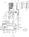
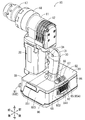
- FIG. 1 shows the overall appearance of the nut tightening machine 10 in perspective.
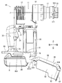
- the side view of FIG. 2 shows the overall appearance of the nut tightening machine 10 in a side view.
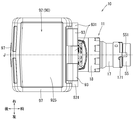
- the rear view of FIG. 3 shows the overall appearance of the nut tightening machine 10 in a rear view.
- the bottom view of FIG. 4 shows the overall appearance of the nut tightening machine 10 in a bottom view.
- the side view of FIG. 5 shows the nut tightening machine 10 of FIG. 2 with the battery cover opened.
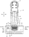
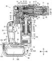
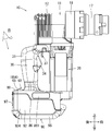
- FIG. 6 shows the internal structure of the nut tightening machine 10.
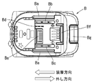
- the bottom view of FIG. 7 shows the battery mounting portions 77 and 77 with the rechargeable batteries B and B removed.
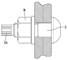
- the side view of FIG. 8 shows that the hexagon nut N is fastened to the shear bolt S.
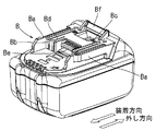
- the perspective view of FIG. 9 shows the external appearance of the rechargeable battery B in perspective. In the plan view of FIG. 10, the rechargeable battery B of FIG. 9 is seen on the mounting surface side. Note that the nut tightening machine 10 will be described based on the front, rear, top, bottom, left and right directions in the drawings.
- the illustrated nut tightening machine 10 is a tool also called a shear wrench.
- This nut tightening machine 10 is used for the purpose of screwing a hexagon nut N to a shear bolt S shown in FIG. That is, the nut tightening machine 10 has a function of tightening the hexagon nut N to the shear bolt S and a function of shearing (cutting) the tip portion Sa provided at the end of the shear bolt S.
- the nut tightening machine 10 roughly includes a tool main body 11, a motor unit 20, and a handle unit 30.
- the tool main body 11 roughly receives the rotational drive from the motor unit 20 and exhibits the above-described tightening function and shearing function.
- the tool body 11 corresponds to a wrench portion according to the present invention in which a hexagon nut N is fastened to the shear bolt S.
- the motor unit 20 and the handle unit 30 are disposed below the tool body 11.
- the motor unit 20 includes a brushless DC motor 22 and generates a rotational driving force.
- the handle portion 30 has a D shape in a side view that can be gripped by the user.
- the motor unit 20 is configured by incorporating a brushless DC motor 22 in a motor housing 21.
- the brushless DC motor 22 corresponds to the motor according to the present invention.
- the brushless DC motor 22 includes a motor shaft 23, a rotor 24, a coil 25, an insulator 26, and a sensor substrate 27.
- the motor shaft 23 is an axis of the rotor 24 and is arranged to extend vertically.
- the motor shaft 23 is rotatably supported by bearings 231 and 232 arranged on the upper and lower sides. These bearings 231 and 232 are supported by the motor housing 21.
- the rotor 24 is supported by the motor shaft 23.
- the coil 25 and the insulator 26 are disposed around the rotor 24 and supported by the motor housing 21.
- the sensor substrate 27 is disposed on the upper side of the rotor 24 and is electrically connected to a controller 70 described later.
- the sensor substrate 27 is configured using a Hall element, and performs detection related to the rotation of the rotor 24. That is, the sensor substrate 27 corresponds to a motor position detection unit according to the present invention.
- the sensor board 27 transmits a position signal to the control processing device 71 (reference numeral 71 shown in FIG. 14) of the controller 70 based on the rotation of the rotor 24.
- a cooling fan 28 that mainly cools the coil 25 is attached to the motor shaft 23.
- the handle portion 30 is a portion that is gripped by the user's hand.
- the handle portion 30 extends in a direction intersecting with the machine axis J serving as a rotation axis for tightening the hexagon nut N.
- the handle portion 30 is set by the outer shape of the handle housing 31.
- the handle housing 31 is selected to have a grip shape that can be easily gripped by hand.
- An operation switch 33 is provided inside the handle housing 31.
- the operation switch 33 corresponds to an operation input unit according to the present invention.
- the operation switch 33 is switched on and off by the user. Specifically, the operation switch 33 is turned on by a pulling operation of a switch lever 34 provided on the front surface, and is automatically turned off when the pulling operation is stopped. If the switch is on, the operation switch 33 transmits an on signal indicating that the switch is on to the controller 70. Conversely, when the switch is off, the operation switch 33 does not transmit an on signal indicating that the switch is on to the controller 70.
- Rotational drive of the motor shaft 23 is transmitted toward the tool body 11.
- a pinion gear 41 is provided at the tip of the motor shaft 23.
- the pinion gear 41 meshes with the first intermediate gear 42.
- the first intermediate gear 42 meshes with the second intermediate gear 43. Therefore, the rotational drive of the motor shaft 23 is transmitted to the intermediate shaft 44 via the two intermediate gears 42 and 43.
- a bevel gear 45 is provided at the tip of the intermediate shaft 44.
- the bevel gear 45 meshes with the input bevel gear 51 of the tool body 11. Therefore, the rotational drive of the intermediate shaft 44 is transmitted to the input shaft 50 integrated with the input bevel gear 51.
- the input shaft 50 is rotatably supported by bearings 521 and 522.
- the bearings 521 and 522 are supported by the main body housing 12. Note that the rotational axis of the input shaft 50 coincides with the machine axis J of the tool body 11.
- a first stage sun gear 52 is provided at the tip of the input shaft 50.
- the first stage sun gear 52 is meshed with the first stage planetary gear train 13 to receive rotational driving.
- the first stage planetary gear train 13 is rotationally transmitted to the second stage planetary gear train 14.
- the second stage planetary gear train 14 is transmitted to the third stage planetary gear train 15 for rotation.
- the rotational drive of the third stage planetary gear train 15 is transmitted to the inner sleeve 16 and the outer sleeve 17.
- the inner sleeve 16 and the outer sleeve 17 are rotatable around the axis J.
- the outer sleeve 17 is integrated with the front housing 18 for rotation about the axis J.
- the front housing 18 is supported to be rotatable about the machine axis J with respect to the main body housing 12.
- the front housing 18 and the outer sleeve 17 rotate integrally.
- the inner sleeve 16 is rotatably supported on the inner ring side of the bearing 19.
- the outer sleeve 17 and the front housing 18 are rotatably supported on the outer ring side of the bearing 19.
- An outer socket 55 is coupled to the front end of the outer sleeve 17.
- a nut fitting portion 56 that allows the above-described hexagon nut N to be fitted is provided on the inner peripheral surface of the outer socket 55.
- the nut fitting portion 56 is a portion into which the hexagon nut N is fitted when the hexagon nut N is tightened.
- the outer socket 55 is coupled to the outer sleeve 17 so as to be axially displaceable and not rotatable relative to the axis.
- the outer socket 55 is disposed coaxially with the inner sleeve 16.
- the outer socket 55 can be removed by displacing it to the front side with respect to the outer sleeve 17.
- An inner socket 57 is supported on the inner peripheral side of the inner sleeve 16 and the outer socket 55.
- the inner socket 57 is urged forward with respect to the inner sleeve 16 by a compression spring 59.
- the outer socket 55 can be displaced rearward against the urging force of the compression spring 59 so as to be relatively close to the outer sleeve 17.
- the female guide portion 551 of the outer socket 55 is guided by the male guide portion 171 of the outer sleeve 17.
- the outer periphery of the inner socket 57 is spline-fitted to the inner periphery of the inner sleeve 16. As a result, the inner sleeve 16 and the inner socket 57 rotate integrally around the axis J.
- a chip fitting portion 58 is provided on the inner peripheral surface of the inner socket 57.
- a slick prevention pin 60 protrudes into the chip fitting portion 58.
- the lick prevention pin 60 is urged by a compression spring 61 in a direction protruding from the inner socket 57.
- the slick prevention pin 60 is retracted from the chip fitting portion 58.
- the stopper 62 provided on the peripheral surface of the inner socket 57 is retracted to the inner peripheral side of the inner socket 57, and the inner socket 57 can be moved to the rear side of the inner sleeve 16.
- the hexagon nut N cannot be fitted to the nut fitting portion 56 of the outer socket 55 unless the chip portion Sa is completely fitted to the chip fitting portion 58 of the inner socket 57. Thereby, the licking with respect to the chip
- the slick prevention pin 60 is integrated with the tip rod 63 so as to be interlocked. That is, when the tip portion Sa is inserted into the tip fitting portion 58 of the inner socket 57, the slick prevention pin 60 and the tip rod 63 are retracted against the compression spring 61. Next, when the tip portion Sa is completely inserted into the tip fitting portion 58, the inner socket 57 is retracted against the compression spring 61. Here, the hexagon nut N shown in FIG. 8 is fitted into the nut fitting portion 56 of the outer socket 55. At this stage, since the inner socket 57 is spline-fitted to the inner sleeve 16, the outer socket 55 is rotated by the rotational drive of the brushless DC motor 22 to tighten the hexagon nut N to the shear bolt S.
- the sheared tip portion Sa is discharged from the tip fitting portion 58 by the output of the slick prevention pin 60 to the front side.
- a discharge lever 37 is provided above the switch lever 34. When the discharge lever 37 is pulled, the tip rod 63 is forcibly moved forward, and the sheared tip portion Sa is forcibly discharged from the tip fitting portion 58.
- the nut tightening machine 10 uses a rechargeable battery B that is detachable as a power source. That is, as shown in FIG. 7, a battery case portion 80 that allows two rechargeable batteries B and B to be mounted is provided below the handle portion 30.
- the battery case portion 80 covers all of the two rechargeable batteries B attached to the two battery attachment portions 77 in a closed state of a battery cover main body 92 described later.
- the battery case unit 80 corresponds to the case unit according to the present invention.
- the battery case unit 80 roughly includes an upper case body 81 and a battery cover 90.
- the upper case body 81 is provided so as to be connected to both the lower part 78 of the motor part 20 and the lower part 79 of the handle part 30.
- On the lower surface of the upper case body 81 the above-described two sets of battery mounting portions 77 and 77 are provided.
- the battery mounting portions 77 and 77 have a configuration that can be attached and detached by sliding the rechargeable batteries B and B in the same direction.
- the rechargeable battery B is a rechargeable battery that is attached to and detached from the battery mounting portion 77 by sliding.
- the rechargeable battery B has a substantially rectangular parallelepiped outer shape as shown in FIGS. 9 and 10.
- a pair of male rails Ba, Ba are provided on both sides with respect to the mounting direction (dismounting direction).
- a positive terminal receiving part Bb and a negative terminal receiving part Bc are provided between the male rail parts Ba and Ba.
- the positive connection terminal 77b of the battery mounting part 77 is connected to the positive terminal receiving part Bb, and the negative connection terminal 77c of the battery mounting part 77 is connected to the negative connection terminal 77c.
- a signal terminal receiving part Bd and a connector part Be are provided between the positive terminal receiving part Bb and the negative terminal receiving part Bc.
- the signal terminal receiving unit Bd is connected to the signal terminal 77d of the battery mounting unit 77, and transmits and receives control signals between the rechargeable battery B and the controller 70.
- the connector unit Be transmits and receives control signals to and from the charger when charging with a charger (not shown).
- a lock claw Bf is provided at the upper rear portion of the rechargeable battery B.
- the lock claw Bf is urged in the engagement direction (projection direction) by a spring disposed inside the rechargeable battery B.
- the lock claw Bf is integrated with the unlock button Bg. Therefore, by depressing the unlock button Bg, the lock claw Bf at the engagement position (projection position) is positioned at the unlock position (retracted position) (not shown), and the rechargeable battery B is removed from the battery mounting portion 77. be able to.
- two sets of battery mounting portions 77 and 77 are provided on the lower surface of the upper case body 81.
- the battery mounting portions 77 and 77 are provided in parallel so that the rechargeable battery B can be attached and detached in the same direction.
- the battery mounting portions 77 and 77 arranged in parallel are electrically connected in series. That is, since two rechargeable batteries B whose voltage is set to 18V are attached, the rated voltage can be imitated with 36V as the total voltage.
- the battery mounting portion 77 is provided with a pair of female rail portions 77a and 77a on both sides with respect to the mounting direction (dismounting direction).
- a positive connection terminal 77b and a negative connection terminal 77c are provided between the female rail portions 77a and 77a.
- a signal terminal 77d is provided between the positive connection terminal 77b and the negative connection terminal 77c.
- An engagement recess 77e to which the lock claw Bf of the rechargeable battery B is engaged is provided on the mounting base end side of the battery mounting portion 77.
- the rechargeable batteries B and B attached to the battery attachment portions 77 and 77 are electrically connected to a controller 70 described later.
- the electric power charged in the rechargeable battery B is supplied to the coil 25 of the brushless DC motor 22 described above. In this manner, the nut tightening machine 10 is used for a DC power source that is supplied with power from the rechargeable battery B.
- the upper case body 81 has an upper surface portion 82 smoothly connected to the motor portion 20 and the lower portions 78 and 79 of the handle portion 30.
- the upper surface portion 82 is formed in a substantially rectangular shape when viewed from above.
- the upper surface portion 82 extends in a substantially horizontal direction, and the front side is slightly inclined downward. That is, the upper surface portion 82 has a substantially planar shape.
- Side surfaces are provided so as to extend downward from the front, rear, left and right edges of the upper surface portion 82.
- a front end portion of the upper surface portion 82 is connected to the upper surface portion 82 so that the front surface portion 83 extends downward.
- the rear end edge of the upper surface portion 82 is slightly connected to the upper surface portion 82 so that the rear surface portion 84 extends downward.
- a left side edge 85 is provided on the left edge of the upper surface 82 so as to be connected to the upper surface 82 so as to extend downward.
- the right surface portion 86 is provided so as to be connected to the upper surface portion 82 so as to extend downward.
- the front surface portion 83 is provided with a pin support portion 831 for attaching a battery cover 90 described below.
- the pin support portion 831 supports the hinge pin 91 in order to hinge-couple the battery cover main body 92. For this reason, the pin support portion 831 is formed to protrude to the front side with an appropriate interval, and is provided with a pin hole 832 into which the hinge pin 91 can be inserted.
- the pin hole 832 extends through the pin support portion 831 in the left-right direction.
- a female hook portion 841 is provided on the rear surface portion 84.
- the female hook portion 841 has a female hook shape for locking the male hook lever 97 provided in the battery cover main body 92.
- rubber bumpers 851 and 861 projecting outward are provided on each of the left side surface portion 85 and the right side surface portion 86. The rubber bumpers 851 and 861 have an action of buffering the contact with the upper case body 81 even when something hits the upper case body 81.
- the battery cover 90 is hinged so that it can be opened and closed when the rechargeable batteries B and B are attached to and detached from the battery mounting portions 77 and 77.
- the battery cover 90 roughly includes a hinge pin 91 and a battery cover main body 92.
- the hinge pin 91 is inserted into the pin hole 832 of the pin support portion 831 described above and supported by the pin support portion 831.
- the hinge pin 91 is also inserted into a pin hole (not shown) of a hinge coupling portion 93 provided on the front wall portion 921 of the battery cover main body 92.
- the battery cover main body 92 is coupled to the upper case body 81 so as to be openable and closable with the hinge pin 91 as a rotation axis. That is, the battery cover main body 92 rotates by using the hinge pin 91 as a rotation shaft, thereby exposing the battery mounting portions 77 and 77 to the outside, and exposing the battery mounting portions 77 and 77 to the outside. It can be displaced to a closed state that does not. That is, the battery cover 90 covers the bottom surfaces of the rechargeable batteries B and B mounted on the battery mounting portions 77 and 77.
- the battery cover main body 92 is configured to have a cover shape that covers the two rechargeable batteries B and B mounted on the two battery mounting portions 77 and 77 described above. For this reason, the battery cover main body 92 has a substantially box shape in which a portion facing the battery mounting portions 77 and 77 is opened.
- the battery cover main body 92 is also formed by connecting a front wall portion 921, a rear wall portion 922, a left wall portion 923, a right wall portion 924, and a bottom wall portion 925.
- the front wall portion 921 is provided with a hinge coupling portion 93 having the above-described pin hole (not shown).
- the front wall portion 921 protects the front side surface of the rechargeable battery B attached to the battery attachment portion 77.
- the rear wall portion 922 protects the rear side surface of the rechargeable battery B attached to the battery attachment portion 77.
- the rear wall 922 is provided with a male hook lever 97 described later.
- the left wall portion 923 and the right wall portion 924 protect the left side surface and the right side surface of the rechargeable battery B attached to the battery attachment portion 77.
- the bottom wall portion 925 protects the bottom surface of the rechargeable battery B attached to the battery attachment portion 77.
- a bottom rubber bumper 96 projecting further outward from the battery cover main body 92 is provided at a corner portion forming the periphery of the bottom wall portion 925. The bottom rubber bumper 96 has an action of buffering the contact with the battery cover main body 92 even when something hits the battery cover main body 92.
- the male hook lever 97 provided on the rear wall portion 922 has a male hook shape that engages with a female hook portion 841 provided on the rear surface portion 84 of the upper case body 81.
- the male hook lever 97 is attached to be tiltable by a hinge shaft 98 supported by the rear wall portion 922. That is, the male hook lever 97 can be locked to the female hook portion 841, and the locking of the male hook lever 97 to the female hook portion 841 can be released by an appropriate operation.
- the closed state of the battery cover main body 92 that closes the battery cover main body 92 so as to cover the rechargeable battery B is maintained. That is, the rechargeable battery B attached to the battery attachment portion 77 is protected by the battery cover main body 92.
- the battery cover main body 92 is moved so that the rechargeable battery B attached to the battery attachment portion 77 is exposed to the outside. It can be in an open state. In this open state, the rechargeable battery B can be attached to or removed from the battery attachment portion 77.
- a controller 70 is provided in the motor unit 20 described above.
- the controller 70 controls the rotational drive of the brushless DC motor 22. Further, the controller 70 controls display output of a counter display 65 described later.
- the controller 70 is built in the lower part of the motor housing 21 that is below the brushless DC motor 22.
- the controller 70 corresponds to a control unit according to the present invention.
- the block diagram of FIG. 14 schematically shows the drive system 100 of the brushless DC motor 22. That is, as shown in FIG. 14, the controller 70 includes a control processing device 71 and a bridge circuit device 72.
- a bolt diameter input dial (not shown) is provided below the controller 70.
- the bolt diameter input dial is a portion where the user inputs the diameter of the bolt to which the hexagon nut N is tightened. That is, there are M16, M20, M22, and M24 as standards for the diameter of the bolt to which the hexagon nut N is tightened. The user can input from the bolt diameter input dial whether the diameter of the bolt to which the hexagon nut N is tightened is M16, M20, M22, or M24.
- the bolt diameter input dial is electrically connected to a control processing device 71 of the controller 70 described later.
- This bolt diameter input dial is shown with reference numeral 39 in the drive system 100 in the block diagram of FIG.
- the bolt diameter input dial 39 sends a bolt diameter signal to the control processing device 71 based on the selected bolt diameter.
- the control processing device 71 includes a CPU (Central Processing Unit) and an appropriate storage medium.
- the bridge circuit device 72 is configured as a switching circuit for driving the brushless DC motor 22 described above.
- the bridge circuit device 72 has a field effector (FET) as a switching element and receives drive control from the control processing device 71. That is, the control processing device 71 performs drive control of the bridge circuit device 72 and also controls display output by the display output unit 66 of the counter display 65 described below.
- the control processing device 71 determines the rated voltage of the rechargeable battery B attached to the battery attachment unit 77.
- the bridge circuit device 72 is directly supplied with power from the rechargeable battery B, and is connected so as to be able to supply power to the coil 25 of the brushless DC motor 22.
- the battery case unit 80 is provided with a counter display 65 for displaying information sent from the controller 70 described later.
- the counter display 65 corresponds to a display unit according to the present invention.
- the counter display 65 indicated by reference numeral 651 is a first example of the counter display 65 and is provided on the rear wall 922 of the battery cover main body 92.
- the counter indicator 65 denoted by reference numeral 651 is provided in a space adjacent to the left side of the male hook lever 97 in the rear wall portion 922.
- the counter indicator 65 indicated by reference numeral 651 is configured such that the counter indicator 65 (651) can be easily seen by the user when the user tightens the nut tightening machine 10 while holding the handle portion 30 with the right hand. .
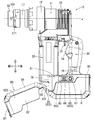
- the counter display 65 shown in FIG. A counter indicator 65 denoted by reference numeral 652 is provided on the upper surface of the battery case unit 80 on the rear side opposite to the front side on which the nut fitting portion 56 is disposed. Specifically, the counter display 65 denoted by reference numeral 652 is provided on the upper surface portion 82 of the upper case body 81. The counter indicator 65 indicated by reference numeral 652 is provided in a space slightly behind the right side of the handle portion 30 in the upper surface portion 82.
- the counter display 65 denoted by reference numeral 652 is also disposed outside (on the right side) the maximum outer peripheral position of the handle portion 30.
- the counter display 65 indicated by the reference numeral 652 is designed to make the counter display 65 (652) easily visible to the user when the user tilts the nut tightening machine 10 to the left while holding the handle portion 30 with the right hand. .
- the counter indicator 65 indicated by reference numeral 653 shown in FIG. It is a rear side opposite to the front side on which the nut fitting portion 56 is arranged, and is provided on the side surface of the battery case portion 80. Specifically, the counter indicator 65 denoted by reference numeral 653 is provided on the right wall portion 924 of the battery cover main body 92. The counter indicator 65 indicated by reference numeral 653 is provided in a space behind the rubber bumper 861 in the right wall portion 924.
- the counter indicator 65 indicated by reference numeral 653 is provided in a space below the rubber bumper 861 and above the bottom rubber bumper 96 in the right wall portion 924.
- the counter indicator 65 denoted by reference numeral 653 is configured such that the counter indicator 65 (653) is easily visible to the user when the user tilts the nut tightening machine 10 to the left while holding the handle portion 30 with the right hand. .
- the counter display 65 may be provided as shown in FIG. That is, the perspective view of FIG. 11 is a nut tightening machine 10 showing a fourth example (indicated by reference numeral 654) of the counter indicator 65.
- the right side view of FIG. 12 shows the right side of the nut tightening machine 10 of FIG.
- a counter indicator 65 denoted by reference numeral 654 shown in FIGS. 11 and 12 is a rear side opposite to the front side on which the nut fitting portion 56 is arranged, and is provided on the upper surface portion 82 of the battery case portion 80. It has been.
- the counter indicator 65 indicated by reference numeral 654 can be said to be an example in which the counter indicator 65 indicated by reference numeral 652 described above is disposed on the rear side of the handle portion 30.
- the counter display 65 denoted by reference numeral 654 is provided with an inclined base 68 that is slightly inclined toward the rear side. That is, the counter indicator 65 indicated by the reference numeral 654 is disposed on the outer side (rear side) than the maximum outer peripheral position (the reference numeral 69) of the handle portion 30.
- the counter indicator 65 indicated by reference numeral 654 is provided on the upper surface 82 of the upper case body 81 and in the space behind the handle portion 30.
- the counter display 65 indicated by the reference numeral 654 is provided on the tilt base 68 as shown in FIG.
- the inclined base 68 is set so that the display surface of the provided counter indicator 65 is slightly rearward. That is, the tilting table part 68 sets the display surface of the counter indicator 65 in a direction inclined with respect to the axial direction in which the handle part 30 extends.
- the tilt base 68 sets the display surface of the counter indicator 65 in a direction that is also tilted with respect to the front-rear direction orthogonal to the axial direction in which the handle 30 extends. For this reason, even when the handle portion 30 is gripped by a hand so as to extend in the vertical direction, the counter indicator 65 indicated by the reference numeral 654 is easily visible to the user without tilting the nut tightening machine 10.
- the counter display 65 may be provided as shown in FIG. That is, the left side view of FIG. 13 is a nut tightening machine 10 showing a fifth example (indicated by reference numeral 655) of the counter indicator 65.
- a counter indicator 65 denoted by reference numeral 655 shown in FIG. 13 is provided on the left side surface portion 85 of the upper case body 81.
- the counter indicator 65 indicated by reference numeral 655 is provided with a rubber bumper 855 so as to border the periphery of the counter indicator 65.
- the rubber bumper 855 is provided so as to protrude outward like the rubber bumpers 851 and 861 described above. For this reason, this rubber bumper 855 also has the same effect as the rubber bumpers 851 and 861 described above, and can also protect the display surface of the counter display 65 indicated by reference numeral 655. In addition, the counter indicator 65 indicated by the reference numeral 655 becomes easy for the user to see the counter indicator 65 (653) when the nut clamping device 10 is tilted to the left while the user grasps the handle portion 30 with the right hand. Yes.
- the five counter displays 65 (indicated by reference numerals 651 to 655) described above are merely examples in which the counter display 65 is provided in the battery case unit 80. That is, the counter indicator 65 may be provided in any part of the upper case body 81 in the upper surface portion 82, the front surface portion 83, the rear surface portion 84, the left side surface portion 85, and the right side surface portion 86.
- the counter indicator 65 is provided at any part of the battery cover main body 92 in the front wall portion 921, the rear wall portion 922, the left wall portion 923, the right wall portion 924, and the bottom wall portion 925. Also good. However, it is preferable to consider the positions of the motor unit 20 and the handle unit 30 as the position where the counter indicator 65 is installed.
- the structure of opening and closing the battery cover 90 as the position where the counter indicator 65 is installed. Further, it is preferable to consider the positions where the rubber bumpers 851 and 861 and the bottom rubber bumper 96 are provided as the positions where the counter display 65 is installed. In particular, the position where the counter indicator 65 is installed is preferably provided in the upper case body 81 formed integrally with the motor housing 21 in which the controller 70 is housed. Further, it is preferable that the counter indicator 65 is easily visible to the user by slightly tilting the nut tightening machine 10.
- the counter display 65 generally includes a display output unit 66 and a counter reset button 67.
- the display output unit 66 is configured to display and output a two-digit number.
- the display output unit 66 is provided with two 7-segment displays that can display and output single-digit numbers. This 7-segment display is composed of LEDs (Light Emitting Diodes) that are widely used.
- the display output unit 66 performs display output under the control of display output from the control processing device 71 described above.
- the display output control includes a primary tightening count number obtained by counting the number of driving brushless DC motors 22. This primary tightening count corresponds to information sent from the controller 70 according to the present invention.
- the counter reset button 67 is provided on the right side of the display output unit 66.
- the counter reset button 67 is electrically connected to the control processing device 71 so as to transmit a reset signal.
- the counter reset button 67 is for setting the primary tightening count number stored in the control processing device 71 to zero.
- the counter reset button 67 sends a reset signal to the control processing device 71 when the counter reset button 67 is pressed.
- the control processing device 71 changes the primary tightening count number stored in the control processing device 71 to zero. That is, the primary tightening count number stored in the control processing device 71 is zero.
- the various configurations described above constitute a drive system 100 as shown in the block diagram of FIG.
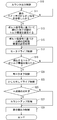
- the drive system 100 performs counter output control shown in FIG. That is, the flowchart of FIG. 15 shows a flow of counter output control.
- the counter output control S10
- the control processing device 71 sets the torque threshold value of the brushless DC motor 22 that is tightened based on the bolt diameter signal sent from the bolt diameter input dial 39 described above.
- the torque threshold value of the brushless DC motor 22 includes a threshold value for the rotational speed of the brushless DC motor 22, a threshold value for the current value of the electric power sent to the brushless DC motor 22, and the like.
- the torque threshold set in S13 is used to determine the torque threshold for the completion of tightening in S19.
- the process proceeds to S15.
- the control processing device 71 sets a primary tightening rotation speed threshold based on the bolt diameter signal sent from the bolt diameter input dial 39 described above.
- the primary tightening rotation speed threshold value set in S15 is used to determine whether or not the rotation for tightening the hexagon nut N by rotating the hexagon nut N is the primary tightening rotation of the hexagon nut N.
- control processing device 71 performs motor drive control (S17). That is, electric power is supplied to the brushless DC motor 22 so as to tighten the hexagon nut N fitted to the nut fitting portion 56. Thereafter, the control processing device 71 determines whether the torque detected from the brushless DC motor 22 has exceeded the torque threshold set in S13 (S19). Specifically, the control processing device 71 calculates and detects the torque of the brushless DC motor 22 based on the position signal sent from the sensor substrate 27.
- the control processing device 71 determines whether the detected torque has exceeded the torque threshold set in S13.
- the control processing device 71 stops the power supply to the brushless DC motor 22 (S21). ). That is, the control processing device 71 performs motor-off control (S21).
- the control processing device 71 determines in S19 that the detected torque of the brushless DC motor 22 does not exceed the torque threshold set in S13, the control processing device 71 does not perform motor-off control (S21).
- the motor drive control (S17) is continued.
- the torque detected by the control processing device 71 is the rotational speed of the brushless DC motor 22 calculated by the control processing device 71 based on the position signal sent from the sensor substrate 27, or It may be the current value of the brushless DC motor 22 calculated by the control processing device 71 by detecting the transmitted power.
- This scavenging drive control is a drive control for removing the hexagon nut N from being locked so as to bite the nut fitting portion 56 by the rotation for tightening the hexagon nut N.
- the control processing device 71 performs motor drive control in which the brushless DC motor 22 is slightly rotated backward after stopping the brushless DC motor 22 in S21.
- the galling is eliminated immediately, so that the brushless DC motor 22 is immediately controlled to be turned off.
- the control processing device 71 performs primary tightening determination (S25).
- primary tightening determination process it is determined whether or not the rotational speed of the brushless DC motor 22 detected by the sensor substrate 27 has exceeded the primary tightening rotational speed threshold set in S15.
- the rotational speed detected by the sensor board 27 exceeds the primary tightening rotational speed threshold, it is determined that the motor drive control in S17 described above is the primary tightening tightening, and the next count-up process (S27) Move on.
- the control processing device 71 In the count-up process (S27), the control processing device 71 first reads the primary tightening count number stored in the control processing device 71. Then, the control processing device 71 increases the count number by “+1” to the read primary tightening count number. Thereafter, the control processing device 71 stores the primary tightening count number increased by “+1” in the control processing device 71 again. After the count-up process (S27), the process proceeds to display output control (S29). In this display output control (S29), the control processing device 71 reads the primary tightening count number stored in the control processing device 71 and outputs it to the display output unit 66 of the display 65 described above. Thereby, the user can grasp
- the following operational effects can be achieved. That is, according to the nut tightening machine 10 described above, since the counter indicator 65 is provided in the battery case unit 80, the user can grasp the information sent from the controller 70. In addition, since this information is information sent from the controller 70 that controls the driving of the brushless DC motor 22, it can be said that the information relates to the tightening of the hexagon nut N.
- the user can grasp information related to the tightening of the hexagon nut N. That is, according to the nut tightening machine 10 described above, the information sent from the controller 70 is the number of times the brushless DC motor 22 is driven, so the user counts the brushless counted as the number of tightened hex nuts N. The number of driven DC motors 22 can be grasped. Thus, the user during the tightening operation can grasp how many bolts the hexagon nut N is tightened.
- the counter indicator 65 (651, 652, 653, 654, 655) is disposed radially outward from the outer peripheral surface of the handle portion 30, so that the user can handle the handle portion 30.
- the counter indicator 65 can be seen while holding the.
- the display surface of the counter indicator 65 (654) is inclined with respect to the axial direction in which the handle portion 30 extends. Even if it is held in a state, the display surface of the counter indicator 65 can be viewed from the up and down direction.
- the counter indicator 65 (654) is disposed on the rear surface side and the display surface faces at least upward, so that the user can grasp the handle portion 30 in a normal state.
- the display surface of the counter display 65 is easy for the user to see.
- the counter indicator 65 (654) is provided on the upper surface of the case portion. Therefore, when the user lowers the power tool while holding the handle portion during normal operation, the counter is displayed to the user.
- the display surface of the display device 65 is easy to see.
- the battery case portion 80 is provided so as to cover the bottom surfaces of the rechargeable batteries B, B mounted on the nut tightening machine 10, so that the mounted rechargeable battery B is attached. , B can be protected.
- the battery cover main body 92 can be opened and closed without removing it from the nut tightening machine 10. Further, the battery cover main body 92 can protect the rechargeable batteries B and B that are mounted. Note that the display surface of the counter display 65 (651, 652, 653, 654) is arranged so as not to hit the ground even when the nut tightening machine 10 is dropped.
- the nut tightening machine according to the present invention is not limited to the above-described embodiment, and may be configured by appropriately changing the location.
- the brushless DC motor 22 is used as a drive source.
- a brush motor may be used.
- the battery cover main body 92 is hinged by the hinge pin 91.
- the configuration of the battery cover according to the present invention may be integrated with the upper case body 81.
- the wiring structure for providing the counter indicator 65 is not complicated, and the counter indicator 65 can be easily and inexpensively provided. Can be provided.
Abstract
L'invention concerne une machine de serrage d'écrou (10) ayant une batterie rechargeable amovible fixée à celle-ci en tant que source d'énergie. Cette machine de serrage d'écrou (10) entraîne un moteur intégré à courant continu (CC) sans balais en utilisant l'énergie provenant de la batterie rechargeable et serre des écrous hexagonaux sur un boulon de cisaillement. Un boîtier de batterie est agencé autour de la batterie rechargeable (B) fixée à la machine de serrage d'écrou (10). Un écran de compteur (654) est agencé dans une section de surface supérieure (82) d'un corps de boîtier supérieur (81) de ce boîtier de batterie. L'écran de compteur (654) comporte en son sein une section de base inclinée (68) qui est inclinée petit à petit vers le côté arrière. Un comptage de serrage primaire est affiché sur l'unité de sortie d'affichage (66) de l'écran (65). Un utilisateur peut vérifier le compte de serrage primaire en regardant le nombre affiché sur l'unité de sortie d'affichage (66).
Applications Claiming Priority (2)
| Application Number | Priority Date | Filing Date | Title |
|---|---|---|---|
| JP2014134249A JP6345510B2 (ja) | 2014-06-30 | 2014-06-30 | ナット締付け機 |
| JP2014-134249 | 2014-06-30 |
Publications (1)
| Publication Number | Publication Date |
|---|---|
| WO2016002293A1 true WO2016002293A1 (fr) | 2016-01-07 |
Family
ID=55018851
Family Applications (1)
| Application Number | Title | Priority Date | Filing Date |
|---|---|---|---|
| PCT/JP2015/061011 WO2016002293A1 (fr) | 2014-06-30 | 2015-04-08 | Machine de serrage d'écrou |
Country Status (2)
| Country | Link |
|---|---|
| JP (1) | JP6345510B2 (fr) |
| WO (1) | WO2016002293A1 (fr) |
Cited By (5)
| Publication number | Priority date | Publication date | Assignee | Title |
|---|---|---|---|---|
| CN108724115A (zh) * | 2017-04-19 | 2018-11-02 | 株式会社牧田 | 电气设备 |
| CN114641599A (zh) * | 2019-11-07 | 2022-06-17 | 工机控股株式会社 | 手持式动力设备 |
| JP7357727B2 (ja) | 2018-07-03 | 2023-10-06 | 株式会社マキタ | 撹拌機 |
| US11894572B2 (en) | 2020-05-22 | 2024-02-06 | Black & Decker Inc. | Power tool with battery pack enclosure |
| EP4338889A1 (fr) * | 2022-09-13 | 2024-03-20 | Black & Decker, Inc. | Outil de serrage à cisaillement |
Families Citing this family (1)
| Publication number | Priority date | Publication date | Assignee | Title |
|---|---|---|---|---|
| TWI691387B (zh) | 2018-11-06 | 2020-04-21 | 朝程工業股份有限公司 | 電動工具 |
Citations (6)
| Publication number | Priority date | Publication date | Assignee | Title |
|---|---|---|---|---|
| JPH06150979A (ja) * | 1992-11-13 | 1994-05-31 | Matsushita Electric Works Ltd | 電池パック |
| JPH08192372A (ja) * | 1995-01-17 | 1996-07-30 | Shibaura Eng Works Co Ltd | ナットランナー |
| JP2005278371A (ja) * | 2004-03-26 | 2005-10-06 | Matsushita Electric Works Ltd | 充電式電気機器 |
| JP2013066991A (ja) * | 2011-09-26 | 2013-04-18 | Makita Corp | 電動工具 |
| JP2013202774A (ja) * | 2012-03-29 | 2013-10-07 | Hitachi Koki Co Ltd | 電動工具及びそれを用いた締付方法 |
| WO2014038376A1 (fr) * | 2012-09-07 | 2014-03-13 | 株式会社マキタ | Dispositif électrique |
Family Cites Families (2)
| Publication number | Priority date | Publication date | Assignee | Title |
|---|---|---|---|---|
| JP3973459B2 (ja) * | 2002-03-15 | 2007-09-12 | 株式会社マキタ | バッテリ駆動式電動工具およびバッテリ駆動式電動工具の使用方法 |
| JP2013226647A (ja) * | 2013-07-08 | 2013-11-07 | Ryobi Ltd | バッテリー式携帯用電動工具 |
-
2014
- 2014-06-30 JP JP2014134249A patent/JP6345510B2/ja not_active Expired - Fee Related
-
2015
- 2015-04-08 WO PCT/JP2015/061011 patent/WO2016002293A1/fr active Application Filing
Patent Citations (6)
| Publication number | Priority date | Publication date | Assignee | Title |
|---|---|---|---|---|
| JPH06150979A (ja) * | 1992-11-13 | 1994-05-31 | Matsushita Electric Works Ltd | 電池パック |
| JPH08192372A (ja) * | 1995-01-17 | 1996-07-30 | Shibaura Eng Works Co Ltd | ナットランナー |
| JP2005278371A (ja) * | 2004-03-26 | 2005-10-06 | Matsushita Electric Works Ltd | 充電式電気機器 |
| JP2013066991A (ja) * | 2011-09-26 | 2013-04-18 | Makita Corp | 電動工具 |
| JP2013202774A (ja) * | 2012-03-29 | 2013-10-07 | Hitachi Koki Co Ltd | 電動工具及びそれを用いた締付方法 |
| WO2014038376A1 (fr) * | 2012-09-07 | 2014-03-13 | 株式会社マキタ | Dispositif électrique |
Cited By (6)
| Publication number | Priority date | Publication date | Assignee | Title |
|---|---|---|---|---|
| CN108724115A (zh) * | 2017-04-19 | 2018-11-02 | 株式会社牧田 | 电气设备 |
| JP7357727B2 (ja) | 2018-07-03 | 2023-10-06 | 株式会社マキタ | 撹拌機 |
| CN114641599A (zh) * | 2019-11-07 | 2022-06-17 | 工机控股株式会社 | 手持式动力设备 |
| EP4056286A4 (fr) * | 2019-11-07 | 2022-11-30 | Koki Holdings Co., Ltd. | Outil électrique portatif |
| US11894572B2 (en) | 2020-05-22 | 2024-02-06 | Black & Decker Inc. | Power tool with battery pack enclosure |
| EP4338889A1 (fr) * | 2022-09-13 | 2024-03-20 | Black & Decker, Inc. | Outil de serrage à cisaillement |
Also Published As
| Publication number | Publication date |
|---|---|
| JP6345510B2 (ja) | 2018-06-20 |
| JP2016010835A (ja) | 2016-01-21 |
Similar Documents
| Publication | Publication Date | Title |
|---|---|---|
| WO2016002293A1 (fr) | Machine de serrage d'écrou | |
| AU2009200035B2 (en) | Cordless motor assisted torque wrench | |
| US20200047319A1 (en) | Power tool | |
| CA2934727C (fr) | Lumiere portative | |
| JP5409647B2 (ja) | 動力工具及び動力工具の使用方法 | |
| US9783936B2 (en) | Device for screwing and unscrewing bolts and screws by means of a motor-driven screwdriving tool | |
| JP6309369B2 (ja) | ナット締付け機 | |
| US20090229842A1 (en) | Battery pack for use with a power tool and a non-motorized sensing tool | |
| US20070046110A1 (en) | Power tool capable of battery status indication | |
| CA2827321C (fr) | Dispositif d'examen visuel | |
| US7053567B2 (en) | Power tools | |
| WO2015025677A1 (fr) | Outil électrique et polisseur utilisant celui-ci | |
| CA2849798A1 (fr) | Cle dynamometrique electronique prereglee | |
| CN104903058B (zh) | 动力工具 | |
| WO2006009681A8 (fr) | Outil d'entrainement d'element de fixation portable a commande de limitation de couple reglable | |
| JP2016030307A (ja) | 電動工具 | |
| JP2019123027A (ja) | 電動作業機 | |
| CN107398868A (zh) | 电动工作机 | |
| JP6917453B2 (ja) | 高速回転レンチ及びその高速回転レンチに用いるモーターの保護方法 | |
| JP2016010831A (ja) | ナット締め付け機 | |
| CN205835155U (zh) | 电动螺丝刀控制系统 | |
| CN212653361U (zh) | 带有离合的远程扳手 | |
| CN211278275U (zh) | 一种电动螺纹修复和电动扳手一体机 | |
| JP2007217881A (ja) | シャッタ装置 | |
| JP2016013584A (ja) | ナット締付け機 |
Legal Events
| Date | Code | Title | Description |
|---|---|---|---|
| 121 | Ep: the epo has been informed by wipo that ep was designated in this application |
Ref document number: 15814085 Country of ref document: EP Kind code of ref document: A1 |
|
| NENP | Non-entry into the national phase |
Ref country code: DE |
|
| 122 | Ep: pct application non-entry in european phase |
Ref document number: 15814085 Country of ref document: EP Kind code of ref document: A1 |