WO2015198928A1 - 吸収性物品 - Google Patents
吸収性物品 Download PDFInfo
- Publication number
- WO2015198928A1 WO2015198928A1 PCT/JP2015/067404 JP2015067404W WO2015198928A1 WO 2015198928 A1 WO2015198928 A1 WO 2015198928A1 JP 2015067404 W JP2015067404 W JP 2015067404W WO 2015198928 A1 WO2015198928 A1 WO 2015198928A1
- Authority
- WO
- WIPO (PCT)
- Prior art keywords
- width direction
- elastic member
- longitudinal direction
- absorbent article
- absorbent core
- Prior art date
Links
Images


Classifications
-
- A—HUMAN NECESSITIES
- A61—MEDICAL OR VETERINARY SCIENCE; HYGIENE
- A61F—FILTERS IMPLANTABLE INTO BLOOD VESSELS; PROSTHESES; DEVICES PROVIDING PATENCY TO, OR PREVENTING COLLAPSING OF, TUBULAR STRUCTURES OF THE BODY, e.g. STENTS; ORTHOPAEDIC, NURSING OR CONTRACEPTIVE DEVICES; FOMENTATION; TREATMENT OR PROTECTION OF EYES OR EARS; BANDAGES, DRESSINGS OR ABSORBENT PADS; FIRST-AID KITS
- A61F13/00—Bandages or dressings; Absorbent pads
- A61F13/15—Absorbent pads, e.g. sanitary towels, swabs or tampons for external or internal application to the body; Supporting or fastening means therefor; Tampon applicators
- A61F13/45—Absorbent pads, e.g. sanitary towels, swabs or tampons for external or internal application to the body; Supporting or fastening means therefor; Tampon applicators characterised by the shape
- A61F13/49—Absorbent articles specially adapted to be worn around the waist, e.g. diapers
- A61F13/494—Absorbent articles specially adapted to be worn around the waist, e.g. diapers characterised by edge leakage prevention means
Definitions
- the present invention relates to an absorbent article such as a disposable diaper that absorbs waste fluid such as urine.
- the disposable diaper of patent document is provided with the waist elastic member 30, the 1st leak-proof sheet 33, and the 2nd leak-proof sheet 34. As shown in FIG.
- the waist elastic member 30 is configured to overlap both the first fixed rear end portion 38 of the first leakproof sheet 33 and the second fixed rear end portion 43 of the second leakproof sheet 34.
- the waist elastic member 30 is configured to overlap with both the first fixed rear end portion 38 and the second fixed rear end portion 43, the contraction force of the waist elastic member 30 Not only the expansion elastic member 39 of the first leakproof sheet 33 but also the contraction force of the elastic member 30 for the waist and the contraction force of the expansion elastic member 44 of the second leakproof sheet 34 are interlocked, and the second fixed rear end Even the part 43 contracts. If the second fixed rear end portion 43 also shrinks, the area where wrinkles are generated will be too wide, and the influence of the wrinkles makes it difficult to determine the center in the width direction, and the absorbent article such as a disposable diaper and wear It becomes difficult to align with the person's body. Therefore, it is desirable to make it easier to identify the center in the width direction of the absorbent article.
- the present invention has been made in view of the above-described conventional problems, and its object is to make it easier to identify the center in the width direction of the absorbent article.
- the main invention to achieve the above object is A body portion having a longitudinal direction, a width direction, and a thickness direction, and having a ventral side, a crotch and a back side in line in the longitudinal direction is a liquid-permeable top sheet, a liquid-impermeable An absorbent article comprising a back sheet and an absorbent core,
- the longitudinal end of the main body constitutes a waist opening, and a waist elastic member is provided at the end along the width direction.
- the absorbent core is present in a portion of the main body portion on the inner side than the back end in the longitudinal direction, and a portion between the waist elastic member and the absorbent core in the main body portion is The waist elastic member and the absorbent core are not present;
- the body portion is provided with a pair of first solid gathers spaced in the width direction along the longitudinal direction, A pair of second solid gathers are provided along the longitudinal direction on the outer side in the width direction than the first solid gather,
- the first elastic member is disposed in the longitudinal direction, and the first solid end can stand on the skin side in the thickness direction with the first base end that can not stand up and the first base end as a fulcrum 1) having an upright portion side by side in the width direction
- a second elastic member is disposed in the longitudinal direction, and a second base end portion which can not stand up and a second base end portion which can stand on the skin side in the thickness direction with the second base end portion as a fulcrum (2) having two standing portions side by side in the
- the present invention it is possible to provide a region in which contraction in the width direction is less likely to occur in the second fixing portion.
- the region in which shrinkage does not easily occur substantially extends the material, and wrinkles are less likely to be formed outside in the width direction than this region. Therefore, the center in the width direction can be more easily determined with reference to these regions on the left and right sides.
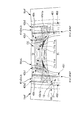
- FIG. 2A, 2B, and 2C are a cross-sectional view taken along the line AA, a cross-sectional view taken along the line BB, and a cross-sectional view taken along the line CC, respectively, in FIG.
- a body portion having a longitudinal direction, a width direction, and a thickness direction, and having a ventral side, a crotch and a back side in line in the longitudinal direction is a liquid-permeable top sheet, a liquid-impermeable
- An absorbent article comprising a back sheet and an absorbent core,
- the longitudinal end of the main body constitutes a waist opening, and a waist elastic member is provided at the end along the width direction.
- the absorbent core is present in a portion of the main body portion on the inner side than the back end in the longitudinal direction, and a portion between the waist elastic member and the absorbent core in the main body portion is The waist elastic member and the absorbent core are not present;
- the body portion is provided with a pair of first solid gathers spaced in the width direction along the longitudinal direction, A pair of second solid gathers are provided along the longitudinal direction on the outer side in the width direction than the first solid gather,
- the first elastic member is disposed in the longitudinal direction, and the first solid end can stand on the skin side in the thickness direction with the first base end that can not stand up and the first base end as a fulcrum 1) having an upright portion side by side in the width direction
- a second elastic member is disposed in the longitudinal direction, and a second base end portion which can not stand up and a second base end portion which can stand on the skin side in the thickness direction with the second base end portion as a fulcrum (2) having two standing portions side by side in the
- the waist elastic member and the first elastic member contract continuously.
- the second fixing portion is separated in the width direction from the expansion / contraction region of the waist elastic member across the first fixing portion, so the contraction force of the waist elastic member and the contraction force of the second elastic member are not interlocked.
- the contraction force of the waist elastic member and the contraction force of the second elastic member are interlocked, and the second fixation portion is obtained. My thigh contracts.
- the region where shrinkage does not easily occur is substantially extended by the material, and wrinkles are not easily formed outside this region in the width direction, and furthermore, only the central region on the back side is sunk inward in the longitudinal direction by the contraction force of the first elastic member Because of the shape, the center in the width direction can be more easily identified with reference to these regions on the left and right sides. In addition, it is difficult for the flap to get under the body, and it is easy to pull it outward in the width direction, so that it is possible to stretch the wrinkles and bumps formed under the user's body and fit the product. Also improves the quality. In addition, it becomes easy to insert the pad when using the absorbent pad as the auxiliary absorption in combination by extending the wrinkles and bumps.
- the second fixing portion be present outside the absorbent core in the longitudinal direction.
- the second fixing portion can be formed closer to the end portion in the longitudinal direction because the second fixing portion is present outside the absorbent core in the longitudinal direction.
- a region in which contraction in the width direction is not easily generated can be provided, and by providing a region in which contraction in the width direction is not easily generated, the center in the width direction is provided.
- the shape of the end in the longitudinal direction in the absorbent core is a curved shape in which the central portion in the width direction protrudes outward in the longitudinal direction more than the end in the width direction. Is desirable.
- the shape of the longitudinal edge of the absorbent core is such that the central portion in the width direction protrudes outward in the longitudinal direction more than the end portion in the width direction. Since it is a curved shape, the waist elastic member and the first upright portion contract along the curved shape by interlocking the contraction force of the waist elastic member and the contraction force of the first elastic member. Therefore, the central portion in the width direction can be easily determined based on the shape contracted along the curved shape. In addition, since the space between the first solid gather and the top sheet formed near the boundary between the first fixed part and the first upright part of the first solid gather can be increased because the thickness of the absorbent core is small, the pocket shape Space can be increased, leakage can be reduced, and an absorbent pad can be easily inserted.
- Such an absorbent article It is desirable that at least the central region in the width direction of the absorbent core be formed to have a basis weight lower than the other regions of the absorbent core.
- the region becomes a mark at the time of wearing of the disposable diaper (absorbent pad) and the fit of the pad is reduced. You can do better. Accordingly, alignment between the widthwise center of the disposable diaper and the center of the user's body (or the widthwise center of the absorbent pad) becomes easier.
- the waist elastic member includes a plurality of thread-like elastic members along the width direction, Of the first fixing portion, the innermost fixed end in the longitudinal direction is located at the non-existing portion, At least a portion of the first fixing portion is provided in a region of the plurality of thread-like elastic members which is sandwiched between the innermost thread-like elastic member in the longitudinal direction and the outermost thread-like elastic member. Is desirable.
- the fixing portion is provided in a region sandwiched by the innermost thread-like elastic member in the longitudinal direction and the outermost thread-like elastic member, thereby standing up in the natural state.
- the plurality of thread-like elastic members are drawn inwardly due to the longitudinal contraction force acting on the portion. Therefore, the end on the back side is formed in a shape (R shape) close to an arc.
- the non-existing portion which is lower in rigidity than other regions, is drawn inward due to the longitudinal contraction force acting on the rising portion.
- a combination of the non-existence portion attracted to the inside and the back portion forms a shape (R-shaped) closer to a circular arc.
- the center of the disposable diaper in the width direction and the body of the wearer Alignment with the center (or the center in the width direction of the absorbent pad) is facilitated.
- there is no elastic member at the end on the back side and a soft region with small rigidity is widely formed, so that the skin feels good even when in contact with the skin of the wearer.
- the first fixing portion be provided over the entire region sandwiched by the innermost thread-like elastic member and the outermost thread-like elastic member in the longitudinal direction.
- Such an absorbent article A region which is located outside the outermost thread-like elastic member in the longitudinal direction at the back end and which contracts as the thread-like elastic member contracts and which is a space between the adjacent thread-like elastic members It is more desirable that a long contraction region be formed in the longitudinal direction.
- the longitudinal length of the contraction area is longer than half of the longitudinal length of the area sandwiched by the outermost thread elastic member and the inner thread elastic member.
- the vicinity of the end on the back side is formed in a shape (R-shaped) close to a more distinct circular arc.
- a back side flap is formed on the back side of the main body to extend outward in the width direction from the main body, and a pair of fastening tapes are provided on both sides in the width direction of the back side flap
- a pair of the fastening tapes each have an engaging portion that engages with the ventral side when the absorbent article is worn,
- a center line connecting the central positions of the pair of engaging portions along the width direction is It is desirable to pass through the non-existing portion at the central portion in the width direction of the absorbent article.
- the pocket in a diaper having a pocket on the rear side, the pocket can be formed cleanly by applying an equal tensile force to the portion where the pocket is formed.
- the longitudinal inner end of the first fixing portion be present outside in the longitudinal direction than a position through which the central line passes.
- the tensile force directed outward in the width direction acting along the center line is likely to act on the entire nonexistent portion without being hindered by the rigid fixing portion. This makes it easier to suppress the occurrence of problems such as the occurrence of wrinkles in the non-existing portion.
- the outer end positions of the pair of engaging portions are defined as the outer end position when the position of the longitudinal outer end at a predetermined position in the width direction of the engaging portion is an outer end position. It is desirable that the straight line connecting along the width direction passes through the portion of the main body portion where the waist elastic member is disposed.
- the inner end positions of the pair of engaging portions are defined as the inner end position of the longitudinal inner end at a predetermined position in the width direction of the engaging portion. It is desirable that a straight line connecting along the width direction passes through a portion of the main body portion in which the absorbent core is disposed.
- the pair of fastening tapes has the engaging portions at a plurality of positions in the longitudinal direction, and the central line is a portion of the plurality of the engaging portions provided in the longitudinal direction. Among them, it is preferable to pass through the central position defined for the engaging portion closest to the position where the waist elastic member is disposed in the longitudinal direction.
- the back side flap and the fastening tape are constituted by different members, and the fastening tape is joined to the widthwise outer end of the back side flap. Is desirable.
- the two sheet members constituting the back side flap and the fastening tape overlap in the thickness direction, and the strength of the joint portion is increased. Can. As a result, even when the fastening tape is strongly pulled to the left and right, it is possible to prevent the joint from being torn or peeled off.
- the absorbent article has a plurality of folds along the width direction, which are base points when the absorbent article is folded in the longitudinal direction, It is desirable that one of the regions in which the plurality of folds are formed passes through the non-existing portion.
- At least one of the plurality of folds is formed to pass through the region of the non-rigid portion with low rigidity, so that the non-existent portion is likely to be creased. .
- This makes it easy to fold the diaper 1 in the longitudinal direction. Furthermore, when the diaper 1 is put in the wearing state, the pocket-like space SP is easily formed.
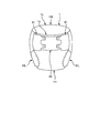
- FIG. 1 is a schematic plan view of the unfolded state (after-mentioned) of the disposable diaper 1 for adults as an absorbent article which concerns on embodiment.
- 2A, FIG. 2B, and FIG. 2C are a cross-sectional view taken along the line AA, a cross-sectional view taken along the line BB, and a cross-sectional view taken along the line CC, respectively, in FIG. 2A to 2C, only one side in the width direction is shown for convenience of the paper.
- FIG. 3 is a schematic perspective view of the disposable diaper 1 in an attached state
- FIG. 3 is a schematic perspective view of the disposable diaper 1 in an attached state
- FIG. 4 is a schematic plan view showing a back side 1 b of the disposable diaper 1 in an enlarged manner.
- FIG. 5 is a schematic cross-sectional view showing how a pocket-like space SP is formed in the main body 1k based on the contraction force of the first solid gather 41g1 (details will be described later).
- the fastening of each fastening tape 61 to the target tape 65 is released, and the abdominal side 1a, the crotch 1m and the dorsal side 1b are aligned in the longitudinal direction While being in the state, the contraction of the first standing portion 41s1 based on the first solid gather elastic member 451 (corresponding to the first elastic member), and the second solid gather elastic member 452 (corresponding to the second elastic member) Until the contraction of the second erecting portion 41s2 based on, the contraction of the back end 1kbeL based on the waist elastic member 71, and the contraction of the rec flap 1mf based on the The disposable diaper 1 is in a stretched state.
- the disposable diaper 1 is a unfolded diaper to be worn by a wearer.
- the disposable diaper 1 has a longitudinal direction, a width direction, and a thickness direction as three directions orthogonal to each other.
- the disposable diaper 1 has a ventral side 1a, a crotch 1m and a back side 1b in this order in the longitudinal direction.
- the abdominal side 1a covers the wearer's ventral side
- the crotch 1m covers the wearer's crotch
- the dorsal side 1b covers the wearer's dorsal side.
- FIG. 1 is a view of the disposable diaper 1 from the skin side.
- the disposable diaper 1 has a sheet-like main body portion 1k as shown in FIGS. 1, 2B and 2C.
- the main body 1k according to the present embodiment includes an absorbent core 11 for absorbing waste fluid such as urine, a top sheet 21 (corresponding to a surface sheet) covering the absorbent core 11 from the skin side in the thickness direction, and Leakproof sheet 30 covering the elastic core 11 from the non-skin side, and an exterior sheet 31 (corresponding to a back sheet) covering the absorbent core 11 from the non-skin side of the leakproof sheet 30 and forming the exterior of the disposable diaper 1 And.
- a solid gather sheet 47 for forming the second solid gather 41g2, a fastening tape 61, a target tape 65, a waist elastic member 71, a leg elastic member 81 and the like are provided to the main body 1k, and disposable.
- the diaper 1 is completed.
- the longitudinal direction, the width direction, and the thickness direction of the main body portion 1k are the same as the longitudinal direction, the width direction, and the thickness direction of the disposable diaper 1, respectively. Therefore, in the following description, the disposable diaper 1 and the main body portion 1k are used without particular distinction in these directions.
- the absorbent core 11 is present in a longitudinally inner portion of the back end 1 kbe L in the main body 1 k (FIG. 1).
- the absorbent core 11 is a liquid absorbent fiber such as pulp fiber, or a liquid absorbent granular material such as a super absorbent polymer (SAP), which is formed into a substantially hourglass shape in plan view as an example of a predetermined shape.
- SAP super absorbent polymer
- the absorbent core 11 is covered with a liquid-permeable core wrap sheet 12 from both the skin side and the non-skin side in the thickness direction (FIG. 2B).
- suitable materials for the core wrap sheet 12 include tissue paper and non-woven fabric.
- the core wrap sheet 12 is not an essential component.
- the top sheet 21 is a flexible and liquid-permeable rectangular sheet that covers the absorbent core 11 from the skin side (FIG. 1, FIG. 2B and FIG. 2C).
- the top sheet 21 covers the core wrap sheet 12 from the skin side while a hot melt adhesive or the like is applied to the core wrap sheet 12. It is fixed by.
- the top sheet 21 has substantially the same size as the absorbent core 11 in the width direction, and pops out from both sides of the absorbent core 11 in the longitudinal direction so as to cover substantially the entire skin side of the absorbent core 11. It has a size.
- the top sheet 21 is provided over the entire length of the disposable diaper 1 in the longitudinal direction (FIG.
- top sheet 21 constitutes a first solid gather 41 g 1 (details will be described later).
- the leak-barrier sheet 30 is a flexible and liquid-impermeable rectangular sheet which covers the absorbent core 11 from the non-skin side (FIGS. 1, 2B and 2C).
- the leakproof sheet 30 in the present embodiment is fixed to the core wrap sheet 12 with a hot melt adhesive or the like while covering the core wrap sheet 12 from the non-skin side.
- the leak-barrier sheet 30 has planar dimensions such that it projects from both sides in the width direction and both sides in the longitudinal direction from the absorbent core 11 so as to cover substantially the entire non-skin side of the absorbent core 11.
- the leak-barrier sheet 30 is provided over the entire length of the disposable diaper 1 in the longitudinal direction (FIG. 1).
- the part of the leak-barrier sheet 30 that protrudes from the absorbent core 11 and the core wrap sheet 12 in the longitudinal direction or the width direction is fixed to the top sheet 21 or the three-dimensional gather sheet 47 with a hot melt adhesive or the like.
- a suitable material for the leakproof sheet 30 can be exemplified by a polyethylene film, it is not limited thereto as long as it has liquid impermeability and flexibility.
- the exterior sheet 31 is a sheet that forms the exterior of the disposable diaper 1 (FIG. 1, FIG. 2B and FIG. 2C).
- the exterior sheet 31 covers the non-skin side of the leakproof sheet 30 and is fixed to the same side with a hot melt adhesive or the like.
- the exterior sheet 31 in the present embodiment has an outer shape of the disposable diaper 1. Therefore, the planar shape of the exterior sheet 31 is substantially hourglass-shaped (FIG. 1). And the exterior sheet 31 protrudes from the leak-proof sheet 30 to both sides in the width direction. The popped out portion is fixed to the three-dimensional gather sheet 47 by a hot melt adhesive or the like.
- the exterior sheet 31 can be exemplified by an SMS (spunbond-meltblown-spunbond) non-woven fabric, it is not limited thereto as long as it has flexibility.
- SMS spunbond-meltblown-spunbond
- the leakproof sheet 30 can be omitted.
- first solid gather 41g1 the solid gather located inside in the width direction
- second solid gather 41 g 2 The solid gather located at the outer side in the width direction than 41 g 1 is referred to as “second solid gather 41 g 2”.
- the first solid gather 41g1 is formed by folding back the end 21ew in the width direction of the top sheet 21 inward in the width direction. That is, the end 21 ew (folded back portion) is the first rising portion 41 s 1.
- the first standing portion 41s1 can stand on the skin side in the thickness direction with the folding line L relating to the folding as a fulcrum. Further, the portion of the folding line L related to the folding is the first base end 41k1 which can not stand up.
- the first base end 41k1 and the first upright portion 41s1 are provided side by side in the width direction.
- one thread rubber of 940 DTEX is natural in the longitudinal direction as an elastic member 451 for the first three-dimensional gather along the longitudinal direction. It is fixed by a hot melt adhesive or the like in a stretched state twice as long as the length.
- a contraction force is applied to the first standing portion 41s1 in the longitudinal direction by the thread rubber.
- the first standing portion 41s1 contracts in the longitudinal direction based on the contraction force, the first standing portion 41s1 stands on the skin side in the thickness direction while forming a plurality of wrinkles, and as a first solid gather 41g1. It functions (FIG. 2B).
- the first three-dimensional gather elastic member 451 is provided on the inner side in the longitudinal direction than the end 1kaeL on the ventral side and the end 1kbeL on the back side.
- the magnitude of the contraction force of the first solid gather elastic member 451 is set, for example, as follows. First, the total length dimension in the longitudinal direction of the first upright portion 41s1 before the first solid gather elastic member 451 is provided (in a state without wrinkles) is defined as a reference length of 100%. When the first erected portion 41s1 provided with the first solid gather elastic member 451 and stretched in the longitudinal direction is extended to 93% in the longitudinal direction, the first solid gather elastic member 451 is 0.5N to 2N.
- the extension state of the first solid gather elastic member 451 at the time of fixing to the first upright portion 41s1 is determined so that the contraction force of For example, in this example, one thread rubber of 940 DTEX is used. Therefore, by setting the stretched state of the single thread rubber in the longitudinal direction to twice the natural length and fixing it to the first upright portion 41s1, the magnitude of the shrinkage force of the thread rubber at 93% stretch is 0. .5N to 2N.
- the respective end portions 41s1eLa, 41s1eLb in the longitudinal direction of the first standing portion 41s1 are the top sheet 21 (main body portion 1k)
- the first fixing portions 42a1 and 42b1 fixed in a state of being superimposed on each other are formed in a band shape along the longitudinal direction. That is, a first fixing portion is formed between the portion corresponding to the first fixing portions 42a1 and 42b1 at the end portions 41s1eLa and 41s1eLb and the portion of the top sheet 21 inward in the width direction than the folding line L.
- Hot melt adhesive etc. are provided in the strip
- Hot melt adhesive etc. are provided in the strip
- the innermost portion 42b1p which is the innermost portion in the longitudinal direction of the first fixed portion 42b1 located in the back side 1b is a waist elastic member 71 and an absorbent core 11 in the main body 1k. Is located in the nonexistent portion 1 kbn (indicated by a dot pattern in FIG. 4).
- the nonexistent portion 1 kbn is a region between the back end 1 kbe L (longitudinal waist elastic member 71) and the absorbent core 11, and has lower rigidity than other regions. .
- the back end 1kbeL is a region located on the outer side in the longitudinal direction with the position of the waist elastic member 71 located on the innermost side in the longitudinal direction in the main body 1k as a starting end.
- the longitudinal dimension of the back end 1 kbe L is selected, for example, in the range of 20 mm to 40 mm in the unfolded state of the disposable diaper 1 as shown in FIG.
- the contraction force of the first solid gather elastic member 451 related to the first rising portion 41s1 is input to the innermost portion 42b1p of the first fixing portion 42b1 in the form of a tensile force F directed inward in the longitudinal direction. Therefore, as shown in FIG. 5, the main body 1k is pulled inward in the longitudinal direction via the innermost portion 42b1p. Therefore, the main body portion 1k is bent in a substantially Z-shaped cross section in the nonexistent portion 1kbn while suppressing the rising of the back end 1kbeL, and between the back end 1kbeL and the absorbent core 11 A pocket-like space SP can be formed at the position.
- “rising of the back end 1 kbe L” refers to a state in which the back end 1 kbe L rises relative to the main body 1 k.
- the back end 1kbeL is raised to the right side of the drawing with respect to the main body 1k.
- the innermost portion 42 b 1 p is located inside the central position C 1 kbn L in the longitudinal direction in the nonexistent portion 1 kbn. Therefore, since the pulling force F directed inward in the longitudinal direction can be input to a position further away from the back end 1kbeL, the rising of the back end 1kbeL can be further suppressed, and the mounting can be performed. Sometimes the back end 1kbeL is less likely to bend inwards, and the face shape can be maintained so that it can fit on the wearer's back.
- the first fixing portion 42 b 1 is formed at a position inside the widthwise central position C 41 sw in the width direction of the first rising portion 41 s 1.
- the first fixed portion 42b1 may be formed outside the central position C41sw in the width direction.
- two auxiliary fixing portions 43b are provided side by side in the width direction at a position between the first fixing portion 42b1 and the first base end 41k1 in the width direction (FIG. 4).
- the auxiliary fixing portion 43b assists the fixation by the first fixing portion 42b1.
- the auxiliary fixing portion 43b crushes the gap between the first rising portion 41s1 and the back end 1kbeL (top sheet 21) which can occur at the position between the first fixing portion 42b1 and the first base end 41k1. Function to prevent urine leakage from the region 41seLb.
- the auxiliary fixing portion 43b is not an essential component.
- the auxiliary fixing portion 43 b is formed of a hot melt adhesive or the like. That is, a hot melt adhesive or the like is interposed in a strip shape along the longitudinal direction between the first standing portion 41s1 and the back end 1kbeL (top sheet 21). As a result, the first upright portion 41s1 and the back end 1kbeL (top sheet 21) are also fixed at a position between the first fixing portion 42b1 and the first base end 41k1 in the width direction.
- the dimension in the width direction of the auxiliary fixing portion 43b in the present embodiment is smaller than the dimension in the width direction of the first fixing portion 42b1, and the innermost portion in the longitudinal direction of the auxiliary fixing portion 43b is the most
- the longitudinal position of the inner portion 43bp is substantially the same as the position of the innermost portion 42b1p of the first fixing portion 42b1, but is not limited thereto. That is, the dimension in the width direction of the auxiliary fixing portion 43b may be larger than that of the first fixing portion 42b1.
- the position of the innermost portion 43bp of the auxiliary fixing portion 43b in the longitudinal direction may be outside or inside the position of the innermost portion 42b1p of the first fixing portion 42b1 in the longitudinal direction.
- the innermost portion 43 bp of the auxiliary fixing portion 43 b be located in the nonexistent portion 1 kbn.
- the second solid gather 41 g 2 is formed of a solid gather sheet 47 which is a separate member from the top sheet 21.
- the three-dimensional gather sheet 47 is provided to cover the first base end 41k1 from the skin side in the thickness direction while being disposed so as to straddle the first base end 41k1 pertaining to the first solid gather 41g1 in the width direction.
- the three-dimensional gathers sheet 47 is fixed to the top sheet 21 at the first base end 41k1 or in the vicinity thereof with a hot melt adhesive or the like, and the fixed part becomes the second base end 41k2 which can not stand up. There is.
- a portion of the three-dimensional gather sheet 47 that is folded back to the outside in the width direction than the second base end 41k2 is a second rising portion 41s2 that can stand up using the second base end 41k2 as a fulcrum.
- a single thread rubber of 940 DTEX extends twice the natural length in the longitudinal direction as a second solid gather elastic member 452 along the longitudinal direction. It is fixed by a hot melt adhesive etc. in the state. Therefore, a contraction force is applied to the second standing portion 41s2 in the longitudinal direction, and the second standing portion 41s2 contracts a plurality of wrinkles by the second standing portion 41s2 contracting in the longitudinal direction based on the contraction force.
- the second three-dimensional gather elastic member 452 is provided on the inner side in the longitudinal direction than the end 1kaeL on the ventral side and the end 1kbeL on the back side.
- a suitable non-woven fabric can be exemplified as a suitable material for the three-dimensional gather sheet 47, and although an SMS non-woven fabric is used here, it is not limited thereto as long as it has flexibility.
- the three-dimensional gather sheet 47 extends to the outer side in the width direction to almost the same position as the outer edge 31ew of the exterior sheet 31, and the outer edge It is adhered to the exterior sheet 31 with a hot melt adhesive or the like at or near 31 ew.
- the three-dimensional gather sheet 47 and the exterior sheet 31 cooperate with each other to form a ventral side flap 1asf at the ventral side 1a and a dorsal side flap 1bsf at the dorsal side 1b.
- the three-dimensional gather sheet 47 and the exterior sheet 31 are similarly bonded and integrated by the hot melt adhesive or the like at the outer edge 31 ew or in the vicinity thereof.
- the leg flap 1 mf is formed over a predetermined range inward in the width direction from the outer edge 31 ew.
- the leg flap 1 mf is a portion (portion covering the periphery of the leg of the wearer) which becomes the leg-surrounding opening HL in the mounted state.
- a plurality of thread rubbers extending in the longitudinal direction as the leg elastics 81 is a hot melt adhesive etc. It is fixed by.
- the leg flaps 1mf contract in the longitudinal direction to form a plurality of creases, and the creases function as leg gathers.
- the second standing portion 41s2 is in the state of an open position where the second base end portion 41k2 or its vicinity is folded back to the outside in the width direction. It has become.
- second fixing portions 42a2 and 42b2 are provided at the respective end portions 41s2eLa and 41s2eLb of the second standing portion 41s2 in the longitudinal direction and the end portions are fixed in a state of overlapping with the main body portion 1k , And in the form of a strip along the longitudinal direction (FIG. 1, FIG. 2A, and FIG. 2C).
- the second fixing portions 42a2 and 42b2 are formed of a hot melt adhesive or the like.
- the second erected portion 41s2 folded back to the outside in the width direction is a portion 47p outside the width direction of the second base end 41k2 in the solid gathers sheet 47.
- the outer portion 47p is fixed to the main body 1k with a hot melt adhesive or the like and is a part of the main body 1k.
- the second upright portion 41s2 is overlapped with the portion 47p of such a three-dimensional gather sheet 47 in the state of being folded back to the outside in the width direction.
- a hot melt adhesive or the like as the second fixing portions 42a2 and 42b2 is interposed between the second standing portion 41s2 in the stacked state and the portion 47p of the three-dimensional gather sheet 47.
- the second rising portions 41s2 and the portions 47p are fixed at the respective end portions 41s2eLa and 41s2eLb in the longitudinal direction by a hot melt adhesive or the like.
- the innermost portion 42b2p which is the innermost portion in the longitudinal direction, of the second fixing portion 42b2 located in the back side 1b also has a nonexistent portion 1 kbn (dot pattern in FIG. It is desirable to be located in).
- the contraction force of the second solid gather elastic member 452 related to the second rising portion 41s2 is input to the innermost portion 42bp2 in the form of a tensile force F2 directed inward in the longitudinal direction. Therefore, it can contribute to formation of pocket-like space SP (FIG. 5) in the position between back end 1kbeL and absorptive core 11, controlling rising of back end 1kbeL. .
- the magnitude of the contraction force of the second solid gather elastic member 452 is set, for example, by the same method as the first solid gather elastic member 451.
- the innermost portion 42 b 2 p of the second fixed portion 42 b 2 is located inward in the longitudinal direction and the outer side in the width direction than the innermost portion 42 b 1 p of the first fixed portion 42 b 1.
- the innermost portion 42b2p and the innermost portion 42b1p can each ride on a substantially arc-shaped curve that bulges outward in the longitudinal direction.
- the innermost portion 42b2p and the innermost portion 42b1p form the pocket-like space SP into a substantially arc shape in plan view by bending the main body portion 1k into a substantially Z shape in a sectional view at each position Can. And as a result, the fit to the buttocks generally having a substantially arc shape can be improved, and urine leakage can be prevented more effectively.
- the magnitude of the contraction force applied from the second solid gather elastic member 452 to the second upright portion 41s2 is the first solid gather elastic member 451 to the first It is desirable to be larger than the magnitude of the contraction force applied to the rising portion 41s1. That is, the magnitude of the contraction force generated in the elastic member 452 for the second three-dimensional gather at the time of 93% elongation of the second standing portion 41s2 is the elastic member for the first three-dimensional gather at the time of 93% elongation of the first standing portion 41s1. It is preferable that the magnitude of the contraction force generated at 451 be larger.
- a tensile force F2 larger than the tensile force F directed inward in the longitudinal direction input to the innermost portion 42b1p is input to the innermost portion 42b2p.
- the innermost portion 42b2p is pulled and moved inward in the longitudinal direction more than the innermost portion 42b1p.
- the innermost portion 42b2p is located outside in the width direction and longitudinally inward than the innermost portion 42b1p. Therefore, according to the magnitude relationship between the tensile forces F and F2 (F ⁇ F2), the central portion in the width direction in the space SP is urged to be in a substantially arc shape projecting further outward in the longitudinal direction. As a result, the magnitude relation effectively contributes to making the space SP conform to the shape of the buttocks.
- the fastening tape 61 is each provided in the outer edge part of the width direction in a pair of back side side flaps 1bsf, as shown to FIG. 1 and FIG. 2A.
- a flexible substantially rectangular sheet is used as the tape base material 61a, one end in the width direction of the tape base 61a is fixed to the outer end of the back side flap 1bsf, and the other end is the back side flap 1bsf It protrudes to the outside in the width direction than the outer end of. At the other end, it protrudes further outward in the width direction at two portions in the longitudinal direction, and one male member 61m of the surface fastener is fixed to the skin side surface of the two protruding portions 61ap. There is.
- a plurality of locking projections are provided on the skin side surface of the male member 61m.
- any known fastener as a hook-and-loop fastener (for example, a hook-like or T-shaped locking projection) can be used as appropriate.
- the material suitable for the tape base material 61a can illustrate flexible sheet materials, such as a nonwoven fabric, it is not restricted to this.
- the target tape 65 is provided in the non-skin side of the exterior sheet 31 which is the non-skin side of the belly side 1a, as shown to FIG. 1 and FIG. 2C.
- the target tape 65 has a substantially rectangular shape elongated in the width direction, and is fixed to the exterior sheet 31 by a hot melt adhesive or the like while aligning the center positions in the width direction with the exterior sheet 31.
- suitable materials for the target tape 65 include, but are not limited to, a film in which a female material is disposed, an air through non-woven fabric, and the like.
- the waist elastic member 71 applies a contraction force in the width direction to the back end 1kbeL so that the waist opening HB in the back side 1b can be expanded and contracted in the width direction, as shown in FIG. It is a member.
- the dimension in the width direction of the waist elastic member 71 provided at the back end 1kbeL is selected, for example, from 180 mm to 220 mm in the unfolded state.
- a plurality of thread-like elastic members extending in the width direction as the waist elastic member 71 are provided side by side in the longitudinal direction.
- the thread-like elastic member five 940 DTEX thread rubbers 71a to 71e are arranged to extend along the width direction.
- Each thread rubber is at least one sheet (top sheet 21 or leakproof sheet 30) while being interposed between the top sheet 21 and the leakproof sheet 30 in the width direction, for example, in an extended state twice the natural length. Is fixed with a hot melt adhesive or the like. Therefore, when the stretched state is relaxed and brought into the natural state, the back end 1kbeL contracts in the width direction, and a plurality of wrinkles are formed.
- each thread rubber can be rapidly expanded in the width direction until the wrinkles are expanded, and the waist-opening portion HB can be expanded and contracted in the width direction.
- each end of the thread-like elastic member is fixed to at least one sheet (the top sheet 21 or the leakproof sheet 30) in a natural state by a hot melt adhesive or the like. Therefore, the waist elastic member 71 has an area that can expand and contract in the width direction (corresponding to the expansion and contraction area 72 (FIG. 6)), and also has an area that does not expand and contract at its end.
- the contraction force of the waist elastic member 71 is set, for example, as follows. First, the total length dimension in the width direction of the back end 1 kbeL before the waist elastic member 71 is provided (in the absence of wrinkles) is defined as a reference length of 100%. Then, when the waist side elastic member 71 is provided and the back end 1kbeL contracted in the width direction is extended to 93% in the width direction, a contraction force of 2N to 8N in total is generated in the waist circumference elastic member 71, The extension state of the waist elastic member 71 at the time of fixing to the back end 1kbeL is determined.
- five yarns at 93% elongation are set by setting the extension state of the five thread rubbers 71a to 71e in the longitudinal direction to twice the natural length and fixing it to the back end 1kbeL.
- the sum of the magnitudes of the contraction forces of the thread rubbers 71a to 71e is stored in 2N to 8N.
- the central portion 11ebc in the width direction is longer than the end portion 11ebe in the width direction. It has a curved shape that protrudes to the outer side (back side) of the direction (that is, the end edge 11eb is formed in an arc shape).
- the shape of the pocket-like space SP when viewed from the skin side in the thickness direction can be formed into a curved shape. That is, since the rigidity of the absorbent core 11 is generally high, when the nonexistent portion 1 kbn is pulled by the pulling force F directed inward in the longitudinal direction, the vicinity of the back end 1kbeL (the back end The 1 kbe L and the nonexistent portion 1 kbn easily bend along the edge 11 eb at a position adjacent to the edge 11 eb of the absorbent core 11. Further, since the shape of the end edge portion 11eb is a curved shape, the vicinity of the back end portion 1kbeL can be bent along the curved shape to form the pocket-like space SP into the curved shape.
- this curved shape is also a shape which follows the shape of a ridge portion generally having a substantially arc shape. Therefore, the pocket-like space SP can be made to go along the buttocks, and through the improvement of the fit to the buttocks, it is possible to more effectively prevent the urine leakage.
- the size in the longitudinal direction of the nonexistent portion 1kbn adjacent to the edge 11eb is Although it changes according to the position in the width direction, it is preferable that the size in the longitudinal direction of the nonexistent portion 1 kbn be set in the following range, including this case. That is, at the position P1 kbn1 where the size in the longitudinal direction is the smallest (in FIG. 4, the central position P1 kbn1 in the width direction), for example, an arbitrary value in the range of 10 mm to 40 mm is set. In FIG.
- the value be in the range of 20 mm to 50 mm. If set in such a range, the size of the pocket-like space SP can be made a size suitable for blocking backflow of urine. For example, if it is larger than the above range, the pocket-like space SP is easily crushed and becomes difficult to function as a weir, while if it is smaller than the above range, the height in the thickness direction of the pocket-like space SP Becomes low, and in this case it becomes difficult to function as a whistle.
- Drawing 6 is an outline top view (plan view seen from the skin side) which expands and shows back side 1b of disposable diaper 1 concerning this embodiment in a natural state.
- the "natural state” refers to a state in which the disposable diaper is spread naturally (a state in which no external force is applied).
- edge part 1kbeL of the back side which the wrinkles have produced in a natural state exists
- description of a wrinkle is abbreviate
- the first fixing portion 42b1 and a part of the stretchable area 72 of the waist elastic member 71 overlap.
- the stretchable area 72 is an area where the waist elastic member 71 can stretch.
- the first fixing portion 42 b 1 is present on the outer side (back side) in the longitudinal direction than the absorbent core 11.
- the second fixing portion 42b2 is separated from the stretchable area 72 of the waist elastic member 71 in the width direction across the first fixing portion 42b1. That is, the second fixing portion 42 b 2 does not overlap with the stretchable area 72 of the waist elastic member 71.
- the contraction force in the expansion and contraction region 72 of the waist elastic member 71 and the elastic member for the first three-dimensional gather by overlapping the expansion and contraction region 72 of the waist elastic member 71 and the first fixing portion 42b1 of the first solid gather 41g1.
- the contraction force by 451 interlocks at the first fixing portion 42b1, and the waist elastic member 71 and the first solid gather elastic member 451 contract continuously.
- the second fixing portion 42b2 is separated in the width direction from the stretchable area 72 of the waist elastic member 71 with the first fixing portion 42b1 in between, the contraction force of the waist elastic member 71 and the elastic member for the second solid gather It is not linked with the contraction force of 452.
- the contraction force of the waist elastic member 71 and the contraction force by the second solid gather elastic member 452 are also interlocked.
- the second fixing portion 42b2 also contracts.
- not only the elastic region 72 of the waist elastic member 71 and the first fixing portion 42b1 but also the second fixing portion 42b2 is contracted in the width direction, and the entire back end is pulled longitudinally inward.
- a spine is formed at the back end, or the back side flap 1bsf is pulled inward in the width direction to get under the user's body and the wearing property is reduced. I will.
- the contraction force of the waist elastic member 71 and the contraction force of the second solid gather elastic member 452 are not interlocked with each other. Therefore, it is possible to provide a region in which contraction in the width direction is less likely to occur in the second fixed portion 42b2.
- the material which is difficult to shrink extends the material substantially, and it is difficult to form wrinkles outside in the width direction from this region, and further, only in the central region on the back side by the shrinking force of the first solid gather elastic member 451 longitudinally inside Since it is in the form of sinking, the center in the width direction can be more easily determined with reference to the hard-to-shrink regions on both the left and right sides.
- the back side flaps 1bsf do not easily enter under the body and are easily pulled outward in the width direction, it is possible to wear the disposable diaper 1 by extending wrinkles and flaps formed under the user's body So the fit to the body also improves. In addition, it becomes easy to insert the pad when using the absorbent pad as the auxiliary absorption in combination by extending the wrinkles and bumps.
- the second fixing portion 42 b 2 is present outside the absorbent core 11 in the longitudinal direction.
- the second fixed portion 42b2 can be formed closer to the end in the longitudinal direction.
- the second fixing portion 42b2 although it is possible to provide a region in which shrinkage in the width direction is not likely to occur, by providing a region in which shrinkage in the width direction is not likely to occur, in the width direction It makes it easy to see the center of
- the elastic region 72 of the rigid waist elastic member 71 maintains the surface shape, so the longitudinal cross section becomes a Z shape and the nonexistent portion 1 kbn
- the pocket-like space SP is formed on the back side, since the pocket-like space SP can be further enlarged by the above configuration, leakage on the back side can be prevented.
- the shape of the longitudinal edge 11eb of the absorbent core 11 has a curved shape in which the central portion in the width direction protrudes outward in the longitudinal direction more than the portion on the end in the width direction. ing.
- the contraction force of the waist elastic member 71 and the contraction force of the first solid gather elastic member 451 interlock with each other.
- the waist elastic member 71 and the first upright portion 41s1 contract along the curved shape. Therefore, the central portion in the width direction can be easily determined based on the shape contracted along the curved shape.
- the innermost portion 42b2p of the second fixed portion 42b2 may not be located in the nonexistent portion 1 kbn.
- the innermost portion 42b2p may be located longitudinally inward of the nonexistent portion 1 kbn.
- the innermost portion 42 b 2 p is located at the back end edge 11 eb of the absorbent core 11. Even in this case, since the innermost portion 42b2p is located near the nonexistent portion 1 kbn, it can contribute to the formation of the pocket-like space SP.
- a flexible sheet-like member 73 such as a nonwoven fabric or a film is provided to cover the waist elastic member 71 from one side or both sides of the skin side and non skin side in the thickness direction. Also good.
- the first solid gather elastic member 451 when the first solid gather elastic member 451 extends across the nonexistent portion 1 kbn and the back end 1 kbe L, the first solid gather elastic member 451. Among them, it is desirable that longitudinal contraction force is not generated in the portion 451p1 located at the back end 1kbeL. Furthermore, it is desirable that the contraction force not be generated similarly for the portion 451p2 located in the nonexistent portion 1 kbn of the first solid gather elastic member 451. In addition to the above, it is desirable that the first three-dimensional gather elastic member 451 have a portion in which the contraction force is not generated inside in the longitudinal direction starting from the position of the innermost portion 42b1p of the first fixed portion 42b1. According to each of these configurations, the rising of the back end 1 kbeL can be more effectively suppressed.
- the innermost portion 42b1p of the first fixing portion 42b1 is the core of the nonexistent portion 1kbn. It is desirable that the wrap sheet 12 be located in a portion where it does not exist. In this case, the innermost portion 42b1p is located at a portion where the core wrap sheet 12 is not present, that is, where the bending stiffness is further reduced.
- a pocket-like space SP can be more reliably formed in 1 kbn.
- the embodiment (the first fixing portion 42a1 formed at the belly-side end 1kaeL of the body 1k) The same device as the first fixing portion 42b1) may be applied.
- first solid gather elastic member 451 (second solid gather elastic member 452)
- a plain rubber, a band-like elastic film, a stretchable non-woven fabric, or the like may be used instead of the thread rubber.
- the first three-dimensional gather elastic member 451 (second The solid gather elastic member 452) can be omitted.
- the first solid gather 41g1 (the first upright portion 41s1) is formed using the end portions 21ew and 21ew in the width direction of the top sheet 21, but the configuration of the first solid gather 41g1 is the same as that of the first solid gather 41g1.
- the first standing portion 41s1 of the first solid gather 41g1 may be formed of a dedicated solid gather sheet (as it is a known configuration, a detailed description will be given) Is omitted).
- the disposable diaper 1 can be used in combination with another absorbent pad (not shown) such as a urine absorbing pad.
- the urine absorption pad is used by placing it on the skin side of the top sheet 21 of the disposable diaper 1. At that time, it is preferable to insert and hold the longitudinal end of the urine absorption pad in the pocket-like space SP. In this way, when the urine absorbing pad is placed on the skin side of the top sheet 21, it becomes easy to position. In addition, since the end of the urine absorbing pad is inserted into the pocket-like space SP, the urine placed on the skin side of the top sheet 21 when laying the disposable diaper 1 under the wearer's body The end of the pad does not hit the wearer's skin.
- the center of the width direction of a disposable diaper and the center in the width direction of an absorptive pad are made into a mark by using the end part vicinity of the back side formed in the shape near a circular arc. Alignment becomes easy.
- the waist elastic member includes a plurality of thread-like elastic members extending in the width direction, and the fixed end located on the innermost side in the longitudinal direction of the first fixing portion is located in the non-existing portion, the first fixing portion At least a part of the plurality of thread-like elastic members, provided in a region between the innermost thread-like elastic member in the longitudinal direction and the outermost thread-like elastic member. It may be a sex item.
- the absorbent article is characterized in that the first fixing portion is provided over the entire region sandwiched between the innermost thread-like elastic member and the outermost thread-like elastic member in the longitudinal direction. It is also good.
- the spine end portion is a region located outside the outermost thread-like elastic member in the longitudinal direction, which is a region that contracts with contraction of the thread-like elastic member, and between adjacent thread-like elastic members
- the absorbent article may be characterized in that a contraction area longer in the longitudinal direction than the interval of.
- the longitudinal length of the contraction area is longer than half of the longitudinal length of the area sandwiched by the outermost thread elastic member and the inner thread elastic member. It may be an absorbent article.
- FIG. 10 is a view for explaining the positional relationship between the male member 61 m (engaging portion) of the fastening tape 61 and the nonexistent portion 1 kbn.
- FIG. 11 is a schematic plan view of the unfolded body of the disposable diaper 1.
- FIG. 12 is a longitudinal sectional view of the diaper 1 in a state of being folded in three. As apparent from FIGS. 10 to 12, the following mode may be adopted.
- a back side flap is formed on the back side of the main body to extend outward in the width direction from the main body, and a pair of fastening tapes are provided on both sides in the width direction of the back side flap
- the pair of fastening tapes each have an engaging portion that engages with the ventral side when the absorbent article is worn, and the longitudinal direction at a predetermined position in the width direction of the engaging portion
- a central line connecting the central positions of the pair of engaging portions along the width direction is the nonexistent portion at the central portion in the width direction of the absorbent article.
- the absorbent article may be characterized in that the inner end portion in the longitudinal direction of the first fixed portion is present in the longitudinal direction outside the position where the central line passes.
- the absorbent article may be characterized in that a straight line passing through passes through a portion of the main body portion where the waist elastic member is disposed.
- the absorbent article may be characterized in that the straight line connecting passes through a portion of the main body portion where the absorbent core is disposed.
- the pair of fastening tapes have the engaging portions at a plurality of positions in the longitudinal direction, and the central line is in the longitudinal direction among the plurality of the engaging portions provided in the longitudinal direction.
- the absorbent article may be characterized in that it passes through the central position defined for the engaging portion closest to the position where the waist elastic member is disposed.
- the back side flap and the fastening tape are configured by different members, and the fastening tape is joined to the widthwise outer end of the back side flap. It may be an article.
- a fold line serving as a base point when the absorbent article is folded in the longitudinal direction is provided with a plurality of folds along the width direction, and a region in which a plurality of folds are formed
- the absorbent article may be characterized in that the rigidity is lower than the area of
- the absorbent core 11 may be provided with a low basis weight area such as a slit.
- slits S1a to S1c are formed in the central region in the width direction of the absorbent core 11.
- the slit S1a is formed on the ventral side 1a.
- the slit S1b is formed in the crotch 1 m.
- the slit S1c is formed in the back side 1b.
- Slits S2a to S2c and slits S3a to S3c are formed outside the central region in the width direction.
- the slit S2a and the slit S3a are formed to sandwich the slit S1a in the abdominal side portion 1a.
- Slit S2b and slit S3b are formed so that slit S1b may be pinched
- the slit S2c and the slit S3c are formed on the back side 1b so as to sandwich the slit S1c.
- Each slit has a lower basis weight than the other regions of the absorbent core 11. That is, at least the central region in the width direction of the absorbent core 11 is formed to have a basis weight lower than the other regions of the absorbent core 11.
- the central region (a part of the central region) in the width direction of the absorbent core 11 in a slit shape and having a low basis weight, wrinkles easily enter the low basis weight, and the core existing region Since the color difference occurs in the non-existing area, the area can be used as a mark when the diaper 1 (absorbent pad) is worn.
- the apex of the back end 1kbeL formed in an arc shape is located substantially on the extension of the central region, the center in the width direction of the back end 1kbeL can be easily understood. Accordingly, alignment between the center in the width direction of the diaper 1 and the center of the body of the wearer (or the center in the width direction of the absorbent pad) becomes easier.
- the absorber when the pad is attached, if the disposable diaper is attached from the outside after fitting the absorbent pad to the body, the absorber is easily bent in the longitudinal direction with the slit as a base point. Can be pressed firmly against the body. Further, by making the basis weight of the absorbent core 11 larger than that of the central region toward the side in the width direction, the position of the absorbent pad does not easily shift, and cracking or the like of the absorbent core can be prevented even in the manufacturing process.
- the diaper 1 before use is in a state of being folded in three in the longitudinal direction.
- the diaper 1 is provided with three fold lines of a first fold line F1 to a third fold line F3.
- the first fold line F1 is formed to pass through the region of the nonexistent portion 1 kbn along the width direction.
- the second fold line F2 is formed to pass through the region between the slit S1c and the slit S1b in the longitudinal direction along the width direction.
- the third fold line F3 is formed to pass through the region between the slit S1b and the slit S1a in the longitudinal direction along the width direction.
- the non-existence portion 1 kbn in which the first fold line F1 is formed has low rigidity as described above.
- the second fold line F2 and the third fold line F3 are formed in a smooth area without the slits S1a to S1c, the resistance at the time of bending in the longitudinal direction is small. Therefore, it becomes easy to fold diaper 1 to a longitudinal direction by making these folds into a starting point.
- the diaper 1 When the diaper 1 is folded in three, first, the back end 1 kbe L of the diaper 1 in the unfolded state is folded to the non-skin side in the thickness direction with the first fold F 1 as a base point. Next, with the second fold line F2 as a base point, the portion of the back side portion 1b of the main body portion 1k is folded so as to face the portion of the crotch 1m and the skin side surface in the thickness direction. Next, it folds so that a part of skin surface side of belly side part 1a of body part 1k may overlap on the non-skin surface side of back side part 1b of body part 1k on the basis of 3rd fold F3. By doing so, the diaper 1 can be folded in a compact state as shown in FIG.
- the first fold line F1 is formed to pass through the non-existence portion 1 kbn area, so the non-existence portion with low rigidity is easily creased. As a result, when the diaper 1 is put in the wearing state, the pocket-like space SP can be easily formed.
- a main body having a longitudinal direction, a width direction, and a thickness direction is an absorbent core that absorbs liquid, a top sheet that covers the absorbent core from the skin side in the thickness direction, and the thickness of the absorbent core
- An absorbent article comprising: a back sheet that covers from the non-skin side of the longitudinal direction, The end in the longitudinal direction of the main body constitutes a waist opening, and a waist elastic member along the width direction in the end to apply contraction force in the width direction to the end.
- the absorbent core is present in a portion in the longitudinal direction in the main body portion more than the end portion, and a portion between the end portion and the absorbent core in the main body portion is the same.
- the waist elastic member and the absorbent core are both absent in the absence of the elastic core,
- a sheet-like solid gatherer is provided along the longitudinal direction at a predetermined position in the width direction,
- the three-dimensional gather has a base end portion which can not stand and a standing portion which can stand on the skin side in the thickness direction with the base end portion as a fulcrum, and acts on the standing portion.
- 1 Disposable diapers (absorbent articles), 1k body, 1kbeL dorsal end, 1 kbn nonexistent part, 11 absorbent core, 12 core wrap sheets, 21 top sheet (front sheet), 30 leak-proof sheet, 31 exterior sheet (back sheet), 41g1 first solid gather, 41g2 second solid gather, 41k1 first base end, 41k2 second base end, 41s1 first standing part, 41s2 second standing part, 42b1 first fixing portion, 42b1p innermost portion, 42b2 second fixed portion, 42b2p innermost portion, 43b Auxiliary fixed part, 43 bp innermost part, 47 three-dimensional gather sheet, 61 Fastening tape, 65 target tape, 71 waist elastic members, 72 stretchable area, SP pocket space, F pull force, F2 pull force,
Abstract
吸収性物品の幅方向の中央をより見定めやすくすること。吸収性物品(1)の本体部(1k)には幅方向に離間した一対の第1立体ギャザー(41g1)が長手方向に沿って設けられており、第1立体ギャザー(41g1)よりも幅方向外側に一対の第2立体ギャザー(41g2)が長手方向に沿って設けられており、第1立体ギャザー(41g1)の第1起立部(41s1)の背側端部には、第1立体ギャザー(41g1)を本体部(1k)に重ねた状態で固定する第1固定部(42b1)が形成されており、第2立体ギャザー(41g2)の第2起立部(41s2)の背側端部には、第2立体ギャザー(41g2)を本体部(1k)に重ねた状態で固定する第2固定部(42b2)が形成されており、第1固定部(42b1)と胴回り弾性部材(71)の伸縮領域とが重なり、第1固定部(42b1)は吸収性コア(11)よりも長手方向において外側に存在し、第2固定部(42b2)は第1固定部(42b1)を挟んで胴回り弾性部材(71)の伸縮領域とは幅方向に離間している。
Description
本発明は、尿等の排泄液を吸収する使い捨ておむつ等の吸収性物品に関する。
使い捨ておむつとしては、例えば特許文献1に記載のものが存在する。特許文献の使い捨ておむつは、胴回り弾性部材30と第1防漏シート33と第2防漏シート34を備える。そして、胴回り用弾性部材30は、第1防漏シート33の第1固定後端部38と第2防漏れシート34の第2固定後端部43の両者に重なる構成を有している。
特許文献1に開示されるように、胴回り用弾性部材30が第1固定後端部38および第2固定後端部43の両者に重なる構成としたならば、胴回り用弾性部材30の収縮力と第1防漏シート33の伸縮性弾性部材39のみならず、胴回り用弾性部材30の収縮力と第2防漏シート34の伸縮性弾性部材44の収縮力も連動してしまい、第2固定後端部43までもが収縮してしまう。第2固定後端部43までも収縮してしまうと、皺の発生する部分も広すぎることになり、その皺の影響により幅方向の中央を見定めにくくなり、使い捨ておむつ等の吸収性物品と着用者の体との位置合わせが困難となる。よって、吸収性物品の幅方向の中央をより見定めやすくすることが望まれる。
本発明は、上記のような従来の問題に鑑みてなされたものであって、その目的は、吸収性物品の幅方向の中央をより見定めやすくすることにある。
上記目的を達成するための主たる発明は、
長手方向と幅方向と厚さ方向とを有し、前記長手方向に関して腹側部と股下部と背側部とを並んで有する本体部が、液透過性の表面シートと、液不透過性の裏面シートと、吸収性コアを有する吸収性物品であって、
前記本体部における前記長手方向の端部は、胴回り開口部を構成するとともに、前記端部には前記幅方向に沿って胴回り弾性部材が設けられており、
前記本体部における前記長手方向の背側端部よりも内側の部分には、前記吸収性コアが存在しているとともに、前記本体部において前記胴回り弾性部材と前記吸収性コアとの間の部分は、前記胴回り弾性部材及び前記吸収性コアが存在しない非存在部分とされており、
前記本体部には幅方向に離間した一対の第1立体ギャザーが前記長手方向に沿って設けられており、
前記第1立体ギャザーよりも幅方向外側に一対の第2立体ギャザーが前記長手方向に沿って設けられており、
前記第1立体ギャザーは、第1弾性部材を前記長手方向に配置し、起立不能な第1基端部と、前記第1基端部を支点として前記厚さ方向の肌側に起立可能な第1起立部とを前記幅方向に並んで有し、
前記第2立体ギャザーは、第2弾性部材を前記長手方向に配置し、起立不能な第2基端部と、前記第2基端部を支点として前記厚さ方向の肌側に起立可能な第2起立部とを前記幅方向に並んで有し、
前記第1起立部のうちの前記背側端部には、前記第1立体ギャザーを前記本体部に重ねた状態で固定する第1固定部が形成されており、
前記第2起立部のうちの前記背側端部には、前記第2立体ギャザーを前記本体部に重ねた状態で固定する第2固定部が形成されており、
前記第1固定部と前記胴回り弾性部材の伸縮領域とが重なり、前記第1固定部は前記吸収性コアよりも前記長手方向において外側に存在し、
前記第2固定部は前記第1固定部を挟んで前記胴回り弾性部材の伸縮領域とは前記幅方向に離間していることを特徴とする吸収性物品である。
本発明の他の特徴については、本明細書及び添付図面の記載により明らかにする。
本発明によれば、第2固定部において幅方向の収縮が生じにくい領域を設けることができる。収縮が生じにくい領域は素材がほぼ延びており、この領域より幅方向に外側においては皺が形成されにくい。よって、左右両側のこれらの領域を基準として、幅方向の中央をより見定めやすくすることができる。
本明細書及び添付図面の記載により、少なくとも以下の事項が明らかとなる。
長手方向と幅方向と厚さ方向とを有し、前記長手方向に関して腹側部と股下部と背側部とを並んで有する本体部が、液透過性の表面シートと、液不透過性の裏面シートと、吸収性コアを有する吸収性物品であって、
前記本体部における前記長手方向の端部は、胴回り開口部を構成するとともに、前記端部には前記幅方向に沿って胴回り弾性部材が設けられており、
前記本体部における前記長手方向の背側端部よりも内側の部分には、前記吸収性コアが存在しているとともに、前記本体部において前記胴回り弾性部材と前記吸収性コアとの間の部分は、前記胴回り弾性部材及び前記吸収性コアが存在しない非存在部分とされており、
前記本体部には幅方向に離間した一対の第1立体ギャザーが前記長手方向に沿って設けられており、
前記第1立体ギャザーよりも幅方向外側に一対の第2立体ギャザーが前記長手方向に沿って設けられており、
前記第1立体ギャザーは、第1弾性部材を前記長手方向に配置し、起立不能な第1基端部と、前記第1基端部を支点として前記厚さ方向の肌側に起立可能な第1起立部とを前記幅方向に並んで有し、
前記第2立体ギャザーは、第2弾性部材を前記長手方向に配置し、起立不能な第2基端部と、前記第2基端部を支点として前記厚さ方向の肌側に起立可能な第2起立部とを前記幅方向に並んで有し、
前記第1起立部のうちの前記背側端部には、前記第1立体ギャザーを前記本体部に重ねた状態で固定する第1固定部が形成されており、
前記第2起立部のうちの前記背側端部には、前記第2立体ギャザーを前記本体部に重ねた状態で固定する第2固定部が形成されており、
前記第1固定部と前記胴回り弾性部材の伸縮領域とが重なり、前記第1固定部は前記吸収性コアよりも前記長手方向において外側に存在し、
前記第2固定部は前記第1固定部を挟んで前記胴回り弾性部材の伸縮領域とは前記幅方向に離間していることを特徴とする吸収性物品である。
このような構成によれば、胴回り弾性部材の伸縮領域と第1立体ギャザーが重なっていることで胴回り弾性部材71の伸縮領域における収縮力と第1弾性部材による収縮力とが第1固定部で連動し、胴回り弾性部材と第1弾性部材とが連続的に収縮する。一方、第2固定部は第1固定部を挟んで胴回り弾性部材の伸縮領域とは幅方向に離間しているので、胴回り弾性部材の収縮力と第2弾性部材の収縮力とは連動しない。
仮に、第2立体ギャザーの第2固定部が胴回り弾性部材の伸縮領域と重なっているとすれば、胴回り弾性部材の収縮力と第2弾性部材による収縮力も連動してしまい、第2固定部までもが収縮してしまう。そうすると、胴回り弾性部材の伸縮領域と第1固定部のみならず、第2固定部も幅方向に収縮する上、背側端部全体が長手方向内側に引っ張られることになるため、寝姿勢で吸収性物品を装着する際に背側端部に皺が形成されたり、フラップが幅方向内側に引っ張られて使用者の体の下に入りこんでしまい、装着性が低下してしまう。
これに対し、上記構成においては前述のように、胴回り弾性部材の収縮力と第2弾性部材の収縮力とは連動しない。よって、第2固定部において幅方向の収縮が生じにくい領域を設けることができる。収縮が生じにくい領域は素材がほぼ延びており、この領域より幅方向に外側においては皺が形成されにくく、さらに、背側の中央域のみ第1弾性部材の収縮力によって長手方向内側に沈み込む形となるため、左右両側のこれらの領域を基準として、幅方向の中央をより見定めやすくすることができる。また、フラップが体の下に入り込みにくく、幅方向外側に引っ張りやすくなるため、使用者の体の下で形成された皺やたくれを伸ばして製品を装着することができるので、体へのフィット性も向上する。また、皺やたくれが伸びることで補助吸収としての吸収性パッドを併用する際にパッドを挿入しやすくなる。
かかる吸収性物品であって、
前記第2固定部は、前記吸収性コアよりも前記長手方向において外側に存在することが望ましい。
前記第2固定部は、前記吸収性コアよりも前記長手方向において外側に存在することが望ましい。
このような吸収性物品によれば、第2固定部が吸収性コアよりも長手方向において外側に存在することから、第2固定部を長手方向の端部寄りに形成することができる。前述のように、第2固定部においては、幅方向の収縮が生じにくい領域を設けることができ、幅方向の収縮が生じにくい領域を長手方向の端部寄りに設けることにより、幅方向の中央を見定めやすくすることができる。さらに、第1立体ギャザーの収縮力により胴回り弾性部材が引っ張られる一方で、剛性ある胴回り弾性部材の伸縮領域は面形状を維持するため、縦断面がZ形状になり非存在部分にポケット状の空間が形成されるが、当該構成によりポケット状の空間をさらに大きくすることができるので、背側の漏れを防止することができる。
かかる吸収性物品であって、
前記吸収性コアにおける前記長手方向の端縁部の形状は、前記幅方向の中央側の部分の方が前記幅方向の端側の部分よりも前記長手方向の外側へ突出した湾曲形状であることが望ましい。
前記吸収性コアにおける前記長手方向の端縁部の形状は、前記幅方向の中央側の部分の方が前記幅方向の端側の部分よりも前記長手方向の外側へ突出した湾曲形状であることが望ましい。
このような吸収性物品によれば、吸収性コアにおける長手方向の端縁部の形状が、幅方向の中央側の部分の方が幅方向の端側の部分よりも長手方向の外側へ突出した湾曲形状であるので、胴回り弾性部材の収縮力と第1弾性部材の収縮力とが連動することで、胴回り弾性部材と第1起立部は湾曲形状に沿って収縮する。よって、湾曲形状に沿って収縮した形状を基準として幅方向の中央部を見定めやすくなる。また、第1立体ギャザーの第1固定部と第1起立部の境界付近に形成される第1立体ギャザーと表面シートの間の空間が、吸収性コアの厚みがない分大きくできるので、ポケット状の空間を大きくすることができ、漏れを低減できる上、吸収性パッドを挿入しやすい。
かかる吸収性物品であって、
少なくとも前記吸収性コアの前記幅方向の中央領域は、前記吸収性コアのそれ以外の領域よりも低目付に形成されていることが望ましい。
少なくとも前記吸収性コアの前記幅方向の中央領域は、前記吸収性コアのそれ以外の領域よりも低目付に形成されていることが望ましい。
このような吸収性物品によれば、吸収性コアの幅方向の中央領域を低目付に形成することにより当該領域を使い捨ておむつ(吸収性パッド)の着用時の目印とするとともに、パッドの収まりをよくすることができる。よって、使い捨ておむつの幅方向の中心と使用者の体の中心(或いは吸収性パッドの幅方向の中心)との位置合わせがより容易となる。
かかる吸収性物品であって、
前記胴回り弾性部材は、前記幅方向に沿う複数の糸状弾性部材を含み、
前記第1固定部のうち前記長手方向の最も内側にある固定端は前記非存在部分に位置し、
前記第1固定部の少なくとも一部は、前記複数の糸状弾性部材のうち、前記長手方向の最も内側の糸状弾性部材と最も外側の糸状弾性部材とに挟まれている領域に設けられていることが望ましい。
前記胴回り弾性部材は、前記幅方向に沿う複数の糸状弾性部材を含み、
前記第1固定部のうち前記長手方向の最も内側にある固定端は前記非存在部分に位置し、
前記第1固定部の少なくとも一部は、前記複数の糸状弾性部材のうち、前記長手方向の最も内側の糸状弾性部材と最も外側の糸状弾性部材とに挟まれている領域に設けられていることが望ましい。
このような吸収性物品によれば、固定部の少なくとも一部を長手方向の最も内側の糸状弾性部材と最も外側の糸状弾性部材とに挟まれている領域に設けることにより、自然状態において、起立部に作用する長手方向の収縮力に基づいて複数の糸状弾性部材が内側に引き寄せられる。よって、背側の端部は円弧に近い形状(R状)に形成される。また、固定端が非存在部分に位置することにより、自然状態において、起立部に作用する長手方向の収縮力に基づいて他の領域よりも剛性の低い非存在部分が内側に引き寄せられる。この内側に引き寄せられた非存在部分と背側の部分とが相俟って、より円弧に近い形状(R状)が形成される。このように、背側の端部近傍(背側の端部及び内側に引き寄せられた非存在部分)を円弧に近い形状に形成することで、使い捨ておむつの幅方向の中心と着用者の体の中心(或いは吸収性パッドの幅方向の中心)との位置合わせが容易となる。また、背側の端部に弾性部材がなく剛性の小さい柔らかい領域が広く形成されることで、着用者の肌に当接しても肌触りがよい。
かかる吸収性物品であって、
前記第1固定部は、前記長手方向の最も内側の糸状弾性部材と最も外側の糸状弾性部材とに挟まれている領域全体にわたって設けられていることが望ましい。
前記第1固定部は、前記長手方向の最も内側の糸状弾性部材と最も外側の糸状弾性部材とに挟まれている領域全体にわたって設けられていることが望ましい。
このような吸収性物品によれば、固定部を、長手方向の最も内側の糸状弾性部材と最も外側の糸状弾性部材とに挟まれている領域全体に渡って設けることにより、自然状態において、起立部に作用する長手方向の収縮力が当該領域全体に作用する。よって、背側の端部近傍は、よりはっきりとした円弧に近い形状(R状)に形成される。従って、使い捨ておむつの幅方向の中心と着用者の体の中心(或いは吸収性パッドの幅方向の中心)との位置合わせがより容易となる。
かかる吸収性物品であって、
前記背側端部には、前記長手方向の最も外側の糸状弾性部材よりも外側に位置し、前記糸状弾性部材の収縮に伴って収縮する領域であって、隣り合う前記糸状弾性部材間の間隔よりも前記長手方向に長い収縮領域が形成されていることが望ましい。
前記背側端部には、前記長手方向の最も外側の糸状弾性部材よりも外側に位置し、前記糸状弾性部材の収縮に伴って収縮する領域であって、隣り合う前記糸状弾性部材間の間隔よりも前記長手方向に長い収縮領域が形成されていることが望ましい。
このような吸収性物品によれば、起立部に作用する長手方向の収縮力に基づいて複数の糸状弾性部材が内側に引き寄せられた場合、このような収縮領域は糸状弾性部材に対して扇状に広がる。よって、背側の端部近傍は、よりはっきりとした円弧に近い形状(R状)に形成される。従って、使い捨ておむつの幅方向の中心と着用者の体の中心(或いは吸収性パッドの幅方向の中心)との位置合わせがより容易となる。
かかる吸収性物品であって、
前記収縮領域の前記長手方向長さは、前記最も外側の糸状弾性部材と前記最も内側の糸状弾性部材とに挟まれる領域の前記長手方向の長さの半分よりも長いことが望ましい。
前記収縮領域の前記長手方向長さは、前記最も外側の糸状弾性部材と前記最も内側の糸状弾性部材とに挟まれる領域の前記長手方向の長さの半分よりも長いことが望ましい。
このような吸収性物品によれば、収縮領域をより長く形成することにより、背側の端部近傍は、更にはっきりとした円弧に近い形状(R状)に形成される。
かかる吸収性物品であって、
前記本体部の背側には、前記本体部から前記幅方向外側に延出する背側サイドフラップが形成されており、前記背側サイドフラップの前記幅方向両側には一対のファスニングテープが設けられており、一対の前記ファスニングテープは、前記吸収性物品の着用時において前記腹側部と係合する係合部をそれぞれ有し、
前記係合部の前記幅方向の所定の位置における前記長手方向中央の位置を中央位置とした場合に、一対の前記係合部の前記中央位置同士を前記幅方向に沿って結ぶ中央線が、前記吸収性物品の前記幅方向の中央部において前記非存在部分を通過することが望ましい。
前記本体部の背側には、前記本体部から前記幅方向外側に延出する背側サイドフラップが形成されており、前記背側サイドフラップの前記幅方向両側には一対のファスニングテープが設けられており、一対の前記ファスニングテープは、前記吸収性物品の着用時において前記腹側部と係合する係合部をそれぞれ有し、
前記係合部の前記幅方向の所定の位置における前記長手方向中央の位置を中央位置とした場合に、一対の前記係合部の前記中央位置同士を前記幅方向に沿って結ぶ中央線が、前記吸収性物品の前記幅方向の中央部において前記非存在部分を通過することが望ましい。
このような吸収性物品によれば、後部側にポケットを有するおむつにおいて、ポケットが形成される部分に均等な引っ張り力を作用させることにより、ポケットをきれいに形成することができるようになる。
かかる吸収性物品であって、前記第1固定部の前記長手方向の内側端部は、前記中央線が通過する位置よりも前記長手方向において外側に存在することが望ましい。
このような吸収性物品によれば、中央線に沿って作用する幅方向外側向きの引っ張り力が剛性の高い固定部によって邪魔されることなく、非存在部分全体に作用しやすくなる。これにより、非存在部分に皺が発生する等の問題が生じることをより抑制しやすくなる。
かかる吸収性物品であって、前記係合部の前記幅方向の所定の位置における前記長手方向外側端の位置を外端位置とした場合に、一対の前記係合部の前記外端位置同士を前記幅方向に沿って結ぶ直線が、前記本体部において前記胴回り弾性部材が配置されている部分を通過することが望ましい。
このような吸収性物品によれば、ファスニングテープを幅方向外側に引っ張ったときに胴回り弾性部材にも引っ張り力が作用しやすくなり、胴回り弾性部材が弛むことなく幅方向外側に伸長される。これにより、長手方向において胴回り弾性部材と隣接して形成される非存在部分も弛むことなく幅方向に伸長させやすくなる。
かかる吸収性物品であって、前記係合部の前記幅方向の所定の位置における前記長手方向内側端の位置を内端位置とした場合に、一対の前記係合部の前記内端位置同士を前記幅方向に沿って結ぶ直線が、前記本体部において前記吸収性コアが配置されている部分を通過することが望ましい。
このような吸収性物品によれば、ファスニングテープを幅方向外側に引っ張ったときに吸収性コアにも引っ張り力が作用しやすくなり、吸収性コアが弛むことなく幅方向外側に伸長される。これにより、長手方向において吸収性コアと隣接して形成される非存在部分も弛むことなく幅方向に伸長させやすくなる。
かかる吸収性物品であって、一対の前記ファスニングテープは、前記長手方向の複数箇所にそれぞれ前記係合部を有し、前記中央線は、前記長手方向に設けられた複数の前記係合部のうち、前記長手方向において前記胴回り弾性部材が配置されている位置に最も近い位置の前記係合部について定められる前記中央位置を通過することが望ましい。
このような吸収性物品によれば、ターゲットテープに対して複数対の係合部を係合させることが可能となり、おむつの装着時において胴回り部のフィット性を高めるとともに、各係合部に作用する力を分散させることができる。これにより、おむつの装着時において意図せず係合部が剥がれてしまうようなことを抑制しつつ、おむつ装着時の形態を保ちやすくすることができる。
かかる吸収性物品であって、前記背側サイドフラップと前記ファスニングテープとが異なる部材で構成されており、前記ファスニングテープは、前記背側サイドフラップの前記幅方向外側端部に接合されていることが望ましい。
このような吸収性物品によれば、接合部において、背側サイドフラップを構成する2シート部材とファスニングテープとが厚さ方向に重複して存在することとなり、当該接合部の強度を高くすることができる。これにより、ファスニングテープを左右に強く引っ張った場合でも接合部が破れたり剥がれたりすることが抑制される。
かかる吸収性物品であって、前記吸収性物品を前記長手方向に折り畳む際の基点となる折り目を前記幅方向に沿って複数有し、
複数の前記折り目が形成される領域のひとつは、前記非存在部分を通過することが望ましい。
複数の前記折り目が形成される領域のひとつは、前記非存在部分を通過することが望ましい。
このような吸収性物品によれば、複数の折り目のうち少なくとも一つの折り目は、剛性の低い非存在部分の領域を通過するように形成されるため、当該非存在部分に折り癖がつきやすくなる。これにより、おむつ1を長手方向に折り畳むことが容易になる。さらに、おむつ1を装着状態にした際に、ポケット状の空間SPを形成しやすくなる。
===実施形態===
<使い捨ておむつの構成>
図1は、実施形態に係る吸収性物品としての大人用の使い捨ておむつ1の展開状態(後述)の概略平面図である。また、図2A、図2B、及び図2Cは、それぞれ、図1中のA-A断面図、B-B断面図、及びC-C断面図である。なお、図2A乃至図2Cでは、紙面の都合上、幅方向の片側のみを示している。また、図3は、装着状態の使い捨ておむつ1の概略斜視図であり、図4は、使い捨ておむつ1の背側部1bを拡大して示す概略平面図である。図5は、第1立体ギャザー41g1の収縮力に基づいて本体部1kにポケット状の空間SPが形成される様子を示す概略断面図である(詳細は後述)。
<使い捨ておむつの構成>
図1は、実施形態に係る吸収性物品としての大人用の使い捨ておむつ1の展開状態(後述)の概略平面図である。また、図2A、図2B、及び図2Cは、それぞれ、図1中のA-A断面図、B-B断面図、及びC-C断面図である。なお、図2A乃至図2Cでは、紙面の都合上、幅方向の片側のみを示している。また、図3は、装着状態の使い捨ておむつ1の概略斜視図であり、図4は、使い捨ておむつ1の背側部1bを拡大して示す概略平面図である。図5は、第1立体ギャザー41g1の収縮力に基づいて本体部1kにポケット状の空間SPが形成される様子を示す概略断面図である(詳細は後述)。
「展開状態」とは、図1に示すように、ターゲットテープ65への各ファスニングテープ61の係止を解いて、腹側部1aと股下部1mと背側部1bとが長手方向に並んだ状態にするとともに、第1立体ギャザー用弾性部材451(第1弾性部材に相当する)に基づく第1起立部41s1の収縮、第2立体ギャザー用弾性部材452(第2弾性部材に相当する)に基づく第2起立部41s2の収縮、胴回り弾性部材71に基づく背側の端部1kbeLの収縮、及び脚回り弾性部材81に基づくレックフラップ1mfの収縮がそれぞれ無くなるまで、長手方向と幅方向との両方向に使い捨ておむつ1を伸ばした状態のことである。
使い捨ておむつ1は、着用者に装着される展開型のおむつである。使い捨ておむつ1は、互いに直交する三方向として長手方向と幅方向と厚さ方向とを有している。使い捨ておむつ1は、腹側部1aと股下部1mと背側部1bとをこの順番で長手方向に並んで有している。図3の装着状態では、腹側部1aは着用者の腹側を覆い、股下部1mは、着用者の股間を覆い、背側部1bは着用者の背側を覆う。
図1の展開状態においては、腹側部1aと背側部1bとは、それぞれ股下部1mよりも幅方向の両側に飛び出している。すなわち、厚さ方向から見た使い捨ておむつ1の外形形状は平面視略砂時計形状をなしている。腹側部1aにおいて幅方向の両側に飛び出した各部分のことを「腹側サイドフラップ1asf」といい、背側部1bにおいて幅方向の両側に飛び出した各部分のことを「背側サイドフラップ1bsf」という。また、以下では、厚さ方向の一方側のことを「肌側」といい、他方側のことを「非肌側」という。図1は、使い捨ておむつ1を肌側から見たものである。
使い捨ておむつ1は、図1、図2B及び図2Cに示すように、シート状の本体部1kを有する。本実施形態に係る本体部1kは、尿等の排泄液を吸収する吸収性コア11と、吸収性コア11を厚さ方向の肌側から覆うトップシート21(表面シートに相当する)と、吸収性コア11を非肌側から覆う防漏シート30と、吸収性コア11を防漏シート30よりも非肌側から覆い、使い捨ておむつ1の外装をなす外装シート31(裏面シートに相当する)と、を有する。
更に、本体部1kに対して、第2立体ギャザー41g2を形成するための立体ギャザーシート47、ファスニングテープ61、ターゲットテープ65、胴回り弾性部材71、及び脚回り弾性部材81などが設けられて、使い捨ておむつ1が完成されている。
なお、本体部1kの長手方向、幅方向、及び厚さ方向は、それぞれ、使い捨ておむつ1の長手方向、幅方向、及び厚さ方向と同じ方向を向いている。そのため、以下の説明では、これらの方向については、使い捨ておむつ1と本体部1kとで特に区別せずに使用する。
以下、図面を参照しながら、使い捨ておむつ1の各構成の詳細について説明する。
吸収性コア11は、本体部1kにおいて背側の端部1kbeLよりも長手方向の内側の部分に存在している(図1)。吸収性コア11は、パルプ繊維等の液体吸収性繊維や高吸収性ポリマー(SAP)等の液体吸収性粒状物を、所定形状の一例としての平面視略砂時計形状に成形したものである。吸収性コア11は、厚さ方向の肌側及び非肌側の両側からそれぞれ液透過性のコアラップシート12によって被覆されている(図2B)。コアラップシート12に好適な材料は、ティッシュペーパーや不織布等を例示できる。但し、コアラップシート12は必須の構成ではない。
トップシート21は、吸収性コア11を肌側から覆う柔軟且つ液透過性の矩形シートである(図1、図2B及び図2C)。本実施形態では吸収性コア11の肌側面がコアラップシート12で被覆されているため、トップシート21は、コアラップシート12を肌側から覆いつつコアラップシート12に対してホットメルト接着剤等で固定されている。また、吸収性コア11の肌側面の概ね全域を覆うべく、トップシート21は、幅方向については吸収性コア11と概ね同じ大きさを有し、長手方向については吸収性コア11の両側から飛び出す大きさを有している。本実施形態では、トップシート21は長手方向について使い捨ておむつ1の全長に亘って設けられている(図1)。トップシート21に好適な材料は、エアスルー不織布を例示できるが、液透過性と柔軟性とを有していればこれに限られない。なお、本実施形態に係るトップシート21は、第1立体ギャザー41g1を構成する(詳細は後述)。
防漏シート30は、吸収性コア11を非肌側から覆う柔軟且つ液不透過性の矩形シートである(図1、図2B及び図2C)。本実施形態における防漏シート30は、コアラップシート12を非肌側から覆いつつ、コアラップシート12に対してホットメルト接着剤等で固定されている。また、防漏シート30は、吸収性コア11の非肌側面の概ね全域を覆うべく、吸収性コア11から幅方向の両側及び長手方向の両側に飛び出すような平面寸法を有する。本実施形態では、防漏シート30は、長手方向について使い捨ておむつ1の全長に亘って設けられている(図1)。そして、防漏シート30のうちで吸収性コア11及びコアラップシート12から長手方向又は幅方向に飛び出す部分は、トップシート21又は立体ギャザーシート47に対してホットメルト接着剤等で固定されている。防漏シート30に好適な材料は、ポリエチレンフィルムを例示できるが、液不透過性と柔軟性とを有していればこれに限らない。
外装シート31は、使い捨ておむつ1の外装をなすシートである(図1、図2B及び図2C)。外装シート31は、防漏シート30の非肌側面を覆いながら、同面にホットメルト接着剤等で固定されている。本実施形態における外装シート31は、使い捨ておむつ1の外形形状をなしている。そのため、外装シート31の平面形状は略砂時計形状となっている(図1)。そして、外装シート31は防漏シート30から幅方向の両側に飛び出している。飛び出した部分は、立体ギャザーシート47に対してホットメルト接着剤等で固定されている。外装シート31に好適な材料は、SMS(スパンボンドーメルトブローン-スパンボンド)不織布を例示できるが、柔軟性を有していればこれに限らない。なお、外装シート31を液不透過性のシートで形成した場合には、防漏シート30を省略できる。
吸収性コア11の幅方向の端部11ewそれぞれに対しては、二つの立体ギャザーが設けられている(図1、図2B及び図2C)。吸収性コア11の幅方向の端部11ewそれぞれに設けられた二つの立体ギャザーのうちで、幅方向の内側に位置する立体ギャザーのことを「第1立体ギャザー41g1」といい、第1立体ギャザー41g1よりも幅方向の外側に位置する立体ギャザーのことを「第2立体ギャザー41g2」という。
図2Bに示すように、第1立体ギャザー41g1は、トップシート21の幅方向の端部21ewが、幅方向の内側へ折り返されることによって形成されている。すなわち、端部21ew(折り返された部分)が、第1起立部41s1となっている。第1起立部41s1は、折り返しに係る折り線Lを支点として厚さ方向の肌側に起立可能となっている。また、折り返しに係る折り線Lの部分が、起立不能な第1基端部41k1となっている。第1基端部41k1と第1起立部41s1とは幅方向に並んで設けられている。第1起立部41s1のうちの幅方向の先端部41sew1(端部21ew)には、長手方向に沿った第1立体ギャザー用弾性部材451として、例えば940DTEXの1本の糸ゴムが長手方向に自然長の2倍の伸長状態でホットメルト接着剤等により固定されている。この糸ゴムにより、第1起立部41s1には長手方向に収縮力が付与される。かかる収縮力に基づいて第1起立部41s1が長手方向に収縮することによって、第1起立部41s1が複数の襞を形成しながら厚さ方向の肌側に起立して、第1立体ギャザー41g1として機能する(図2B)。本実施形態において、第1立体ギャザー用弾性部材451は、腹側の端部1kaeL及び背側の端部1kbeLよりも長手方向の内側に設けられている。
第1立体ギャザー用弾性部材451の収縮力の大きさは、例えば次のように設定される。先ず、第1立体ギャザー用弾性部材451を設ける前(襞が無い状態)の第1起立部41s1の長手方向の全長寸法のことを、100%の基準長さと定義する。そして、第1立体ギャザー用弾性部材451が設けられて長手方向に収縮した第1起立部41s1を長手方向に93%まで伸長した際に、第1立体ギャザー用弾性部材451に0.5N~2Nの収縮力が生じるように、第1起立部41s1へ固定する際の第1立体ギャザー用弾性部材451の伸長状態が決定される。例えば、この例では、940DTEXの1本の糸ゴムを用いている。そのため、当該1本の糸ゴムの長手方向の伸長状態を自然長の2倍に設定して第1起立部41s1に固定することにより、93%伸長時の糸ゴムの収縮力の大きさを0.5N~2Nに収めている。
また、図1、図2A、及び図2Cに示すように、第1起立部41s1の長手方向の各端部41s1eLa,41s1eLbには、当該各端部41s1eLa,41s1eLbをトップシート21(本体部1k)に重ねた状態で固定する第1固定部42a1,42b1が、それぞれ長手方向に沿った帯状に形成されている。すなわち、端部41s1eLa,41s1eLbにおいて第1固定部42a1,42b1に対応する部分と、トップシート21のうちで上記の折り線Lよりも幅方向の内側の部分との間には、第1固定部42a1,42b1としてホットメルト接着剤等が長手方向に沿った帯状に設けられており、当該接着剤によって、端部41s1eLa,41s1eLbはそれぞれトップシート21の部分に重ねられた状態で固定されている。
また、図4等に示すように、背側部1bに位置する第1固定部42b1における長手方向の最も内側の部分たる最内側部分42b1pは、本体部1kにおいて胴回り弾性部材71及び吸収性コア11が存在しない非存在部分1kbn(図4においてドット模様で示す)に位置している。非存在部分1kbnは、背側の端部1kbeL(長手方向の最も内側に位置する胴回り弾性部材71)と吸収性コア11との間の領域であり、他の領域よりも剛性が低くなっている。背側の端部1kbeLは、本体部1kにおいて長手方向の最も内側に位置する胴回り弾性部材71の位置を起端として、そこから長手方向の外側に位置する領域である。背側の端部1kbeLの長手方向の寸法は、図4のような使い捨ておむつ1の展開状態において例えば20mm~40mmの範囲から選択される。
第1固定部42b1の最内側部分42b1pには、第1起立部41s1に係る第1立体ギャザー用弾性部材451の収縮力が長手方向の内側を向いた引っ張り力Fの形態で入力される。よって、図5に示すように、最内側部分42b1pを介して本体部1kは長手方向の内側に引っ張られる。従って、背側の端部1kbeLの立ち上がりを抑制しつつ、本体部1kは、非存在部分1kbnにおいて断面視略Z字形状に屈曲し、背側の端部1kbeLと吸収性コア11との間の位置にポケット状の空間SPを形成することができる。なお、「背側の端部1kbeLの立ち上がり」とは、背側の端部1kbeLが本体部1kに対して起き上がる状態をいう。たとえば、図5において、背側の端部1kbeLが本体部1kに対して紙面右側に起き上がる状態をいう。
ここで、図4に示すように、本実施形態に係る最内側部分42b1pは、非存在部分1kbnにおける長手方向の中央位置C1kbnLよりも内側に位置している。よって、長手方向の内側を向いた引っ張り力Fを、背側の端部1kbeLから更に離れた位置に入力することができるため、背側の端部1kbeLの立ち上がりをより抑制することができ、装着時に背側端部1kbeLが内側に折れ曲がりにくく、面形状を維持できるので着用者の背中にフィットさせることができる。
また、図4において、第1固定部42b1は、第1起立部41s1における幅方向の中央位置C41swよりも幅方向の内側の位置に形成されている。これにより、第1起立部41s1と背側の端部1kbeLとが重なる領域41seLbにおいて、第1起立部41s1を確実に固定できる。但し、第1固定部42b1を中央位置C41swよりも幅方向の外側に形成しても良い。
更に、本実施形態では、幅方向における第1固定部42b1と第1基端部41k1との間の位置に、2つの補助固定部43bを幅方向に並んで設けている(図4)。補助固定部43bは、第1固定部42b1による固定を補助する。補助固定部43bは、第1固定部42b1と第1基端部41k1との間の位置で生じ得る第1起立部41s1と背側の端部1kbeL(トップシート21)との間の隙間を潰すように作用するため、領域41seLbからの尿漏れを有効に防ぐことができる。但し、補助固定部43bは必須構成ではない。
補助固定部43bは、ホットメルト接着剤等で形成されている。すなわち、ホットメルト接着剤等が第1起立部41s1と背側の端部1kbeL(トップシート21)との間に長手方向に沿った帯状に介挿されている。これにより、第1起立部41s1と背側の端部1kbeL(トップシート21)は、幅方向における第1固定部42b1と第1基端部41k1との間の位置においても固定されている。
なお、本実施形態における補助固定部43bの幅方向の寸法は、第1固定部42b1の幅方向の寸法より小さくされているとともに、補助固定部43bのうちで長手方向の最も内側の部分たる最内側部分43bpの長手方向の位置は、第1固定部42b1の最内側部分42b1pの位置とほぼ同じであるが、これに限らない。すなわち、補助固定部43bの幅方向の寸法を、第1固定部42b1より大きくしても良い。また、補助固定部43bの最内側部分43bpの長手方向の位置を、第1固定部42b1の最内側部分42b1pの長手方向の位置よりも外側或いは内側にしても良い。但し、何れの場合についても、補助固定部43bの最内側部分43bpを非存在部分1kbnに位置させていることが望ましい。このように構成することにより、収縮力に基づく長手方向の内側を向いた引っ張り力Fを、効率よく非存在部分1kbnに入力できることから、背側の端部1kbeLの立ち上がりを抑制することができる。
一方、第2立体ギャザー41g2は、図1及び図2Bに示すように、トップシート21とは別部材の立体ギャザーシート47で形成されている。立体ギャザーシート47は、第1立体ギャザー41g1に係る第1基端部41k1を幅方向に跨ぐように配されつつ、第1基端部41k1を厚さ方向の肌側から覆って設けられている。立体ギャザーシート47は、第1基端部41k1或いはその近傍においてトップシート21にホットメルト接着剤等で固定されており、その固定された部分が、起立不能な第2基端部41k2となっている。また、立体ギャザーシート47のうちで第2基端部41k2よりも幅方向の外側に折り返される部分が、第2基端部41k2を支点として起立可能な第2起立部41s2となっている。第2起立部41s2のうちの幅方向の先端部には、長手方向に沿った第2立体ギャザー用弾性部材452として、例えば940DTEXの1本の糸ゴムが長手方向に自然長の2倍の伸長状態でホットメルト接着剤等により固定されている。そのため、第2起立部41s2には長手方向に収縮力が付与されており、かかる収縮力に基づいて第2起立部41s2が長手方向に収縮することによって、第2起立部41s2が複数の襞を形成しながら厚さ方向の肌側に起立して、第2立体ギャザー41g2として機能する(図2B)。本実施形態において、第2立体ギャザー用弾性部材452は、腹側の端部1kaeL及び背側の端部1kbeLよりも長手方向の内側に設けられている。立体ギャザーシート47に好適な材料は、適宜な不織布を例示できて、ここではSMS不織布が使用されているが、柔軟性を有していれば、これに限らない。
また、立体ギャザーシート47は、図1、図2A乃至図2Cに示すように、幅方向の外側の方へ外装シート31の外端縁31ewとほぼ同位置まで延在しており、外端縁31ew或いはその近傍で外装シート31とホットメルト接着剤等で接着されている。これにより、立体ギャザーシート47と外装シート31とが互いに共同して、腹側部1aでは腹側サイドフラップ1asfが形成され、背側部1bでは背側サイドフラップ1bsfが形成される。一方、股下部1mでも、同様に、上記の外端縁31ew或いはその近傍で立体ギャザーシート47と外装シート31とがホットメルト接着剤等で接着一体化されている。これにより、外端縁31ewから幅方向の内側の所定範囲に亘ってレッグフラップ1mfが形成される。
レッグフラップ1mfは、装着状態において脚回り開口部HLとなる部分(着用者の脚回りを覆う部分)である。レッグフラップ1mfを長手方向に収縮させてレッグギャザーを形成すべく、レッグフラップ1mfには、脚回り弾性部材81として長手方向に沿った複数の糸ゴムが長手方向に伸長状態でホットメルト接着剤等により固定されている。脚回り弾性部材81の伸長状態が緩和されると、レッグフラップ1mfは長手方向に収縮して複数の襞が形成されて当該襞がレッグギャザーとして機能する。
なお、図2Bに示すように、第2起立部41s2は、第1起立部41s1とは異なり、第2基端部41k2或いはその近傍を折り返し位置として幅方向の外側に折り返された外開きの状態となっている。この外開きの状態に固定すべく、第2起立部41s2における長手方向の各端部41s2eLa,41s2eLbには、当該端部を本体部1kに重ねた状態で固定する第2固定部42a2,42b2が、長手方向に沿った帯状に形成されている(図1、図2A、及び図2C)。第2固定部42a2,42b2はホットメルト接着剤等で形成されている。
具体的には、図2A及び図2Cに示すように、幅方向の外側に折り返された第2起立部41s2は、立体ギャザーシート47において第2基端部41k2よりも幅方向の外側の部分47pに対向するが、かかる外側の部分47pは、本体部1kにホットメルト接着剤等で固定されていて、本体部1kの一部になっている。そして、このような立体ギャザーシート47の部分47pに、第2起立部41s2が幅方向の外側に折り返された状態で重ねられている。かかる重ねられた状態の第2起立部41s2と、立体ギャザーシート47の部分47pとの間に、第2固定部42a2,42b2としてのホットメルト接着剤等が介挿されている。これにより、第2起立部41s2及び部分47pは、長手方向の各端部41s2eLa,41s2eLbにおいてホットメルト接着剤等により固定されている。
ここで、図4に示すように、背側部1bに位置する第2固定部42b2についても、その長手方向の最も内側の部分たる最内側部分42b2pが、非存在部分1kbn(図4においてドット模様で示す)に位置していることが望ましい。
この場合、最内側部分42bp2には、第2起立部41s2に係る第2立体ギャザー用弾性部材452の収縮力が長手方向の内側を向いた引っ張り力F2の形態で入力される。そのため、背側の端部1kbeLの立ち上がりを抑制しながら、背側の端部1kbeLと吸収性コア11との間の位置へのポケット状の空間SP(図5)の形成に寄与することができる。なお、第2立体ギャザー用弾性部材452の収縮力の大きさは、たとえば、第1立体ギャザー用弾性部材451と同様の方法で設定される。
なお、図4では、第2固定部42b2の最内側部分42b2pは、第1固定部42b1の最内側部分42b1pよりも長手方向の内側且つ幅方向の外側に位置している。
よって、最内側部分42b2p及び最内側部分42b1pは、それぞれ、長手方向の外側に膨出した略円弧形状の曲線上に乗ることができる。最内側部分42b2p及び最内側部分42b1pは、それぞれの位置で本体部1kを断面視略Z字形状に屈曲することにより、ポケット状の空間SPの形状を平面視で略円弧形に作り込むことができる。そして、その結果、一般に略円弧形でなる臀部へのフィット性を良好にして、尿便漏れをより効果的に防止可能となる。
なお、略円弧形に作り込む観点に立てば、第2立体ギャザー用弾性部材452から第2起立部41s2に付与される収縮力の大きさが、第1立体ギャザー用弾性部材451から第1起立部41s1に付与される収縮力の大きさよりも大きくなっていることが望ましい。すなわち、第2起立部41s2の93%伸長時において第2立体ギャザー用弾性部材452に生じる収縮力の大きさの方が、第1起立部41s1の93%伸長時において第1立体ギャザー用弾性部材451に生じる収縮力の大きさよりも大きくなっていると良い。
この場合、最内側部分42b2pには、最内側部分42b1pに入力される長手方向の内側を向いた引っ張り力Fよりも大きな引っ張り力F2が入力される。これにより、最内側部分42b2pは、最内側部分42b1pよりも長手方向の内側へと大きく引っ張られて移動する。また、最内側部分42b2pは、最内側部分42b1pよりも幅方向の外側且つ長手方向の内側に位置している。そのため、引っ張り力F,F2の大小関係(F<F2)によれば、空間SPにおける幅方向の中央部分がより長手方向の外側に突出したような略円弧形状になるように促すこととなって、その結果、当該大小関係は、空間SPを臀部の形状に沿わせることに有効に寄与する。
ファスニングテープ61は、図1及び図2Aに示すように、一対の背側サイドフラップ1bsfにおける幅方向の外端部にそれぞれ設けられている。ファスニングテープ61は、柔軟な略矩形シートをテープ基材61aとし、テープ基材61aの幅方向の一端部が背側サイドフラップ1bsfの外端部に固定され、他端部が背側サイドフラップ1bsfの外端部よりも幅方向の外側に突出している。他端部では、長手方向の2カ所の部分で更に幅方向の外側に突出していて、当該2カ所の突出部61apの肌側面には、それぞれ面ファスナーのオス材61mが一つずつ固定されている。また、オス材61mの肌側面には、複数の係止用突起(不図示)が設けられている。オス材61mの係止用突起が腹側部1aのターゲットテープ65の非肌側面に引っ掛かることにより、ターゲットテープ65にファスニングテープ61が係止される。オス材61mには、面ファスナーとして周知なもの(係止用突起が釣り針状のものやT字状のもの等)を適宜使用することができる。また、テープ基材61aに好適な材料は、不織布等の柔軟なシート材を例示できるが、これに限らない。
ターゲットテープ65は、図1及び図2Cに示すように、腹側部1aの非肌側面たる外装シート31の非肌側面に設けられている。ターゲットテープ65は、幅方向に長い略矩形状であり、外装シート31との間で互いの幅方向の中央位置を合わせつつホットメルト接着剤等によって外装シート31に固定されている。ターゲットテープ65に好適な材料は、メス材を配置したフィルムやエアスルー不織布等を例示できるが、これに限らない。また、ターゲットテープを用いなくても、外装シート自体に不織布など係止用突起がひっかかりやすいものを用いてもよい。
ターゲットテープ65に各ファスニングテープ61を係止することによって、図3に示すように、胴回り開口部HBと一対の脚回り開口部HL,HLとが形成されて、使い捨ておむつ1は着用者に装着される。
胴回り弾性部材71は、図4に示すように、背側部1bにおける胴回り開口部HBを幅方向に伸縮可能にすべく、背側の端部1kbeLに対して、幅方向の収縮力を付与する部材である。背側の端部1kbeLに設けられる胴回り弾性部材71の幅方向の寸法は、展開状態において例えば180mm~220mmから選択される。
背側の端部1kbeLには、胴回り弾性部材71として幅方向に沿う複数の糸状弾性部材が長手方向に並んで設けられている。本実施形態では、糸状弾性部材の例として、5本の940DTEXの糸ゴム71a~71eが、それぞれ幅方向に沿って延在して配されている。各糸ゴムは、幅方向に例えば自然長の2倍の伸長状態で、トップシート21と防漏シート30との間に介挿されつつ、少なくとも一方のシート(トップシート21または防漏シート30)にホットメルト接着剤等で固定されている。よって、伸長状態が緩和されて自然状態にされれば、背側の端部1kbeLは幅方向に収縮して、複数の襞が形成された状態となる。そして、これにより、かかる襞が伸びきるまでは、各糸ゴムは速やかに幅方向に伸長することができ、胴回り開口部HBは幅方向に伸縮可能とされている。ただし、糸状弾性部材のそれぞれの端部は、自然状態で少なくとも一方のシート(トップシート21または防漏シート30)にホットメルト接着剤等で固定されている。そのため、胴回り弾性部材71は、幅方向に伸縮可能な領域(伸縮領域72(図6)に相当)を有するとともに、その端部には伸縮しない領域も有することになる。
胴回り弾性部材71の収縮力は、例えば次のように設定される。先ず、胴回り弾性部材71を設ける前(襞が無い状態)の背側の端部1kbeLの幅方向の全長寸法のことを、100%の基準長さと定義とする。そして、胴回り弾性部材71が設けられて幅方向に収縮した背側の端部1kbeLを幅方向に93%まで伸長した際に、胴回り弾性部材71に合計2N~8Nの収縮力が生じるように、背側の端部1kbeLへ固定する際の胴回り弾性部材71の伸長状態が決定される。例えば、本実施形態では、5本の糸ゴム71a~71eの長手方向の伸長状態を自然長の2倍に設定して背側の端部1kbeLに固定することにより、93%伸長時の5本の糸ゴム71a~71eの収縮力の大きさの合計値を2N~8Nに収めている。
なお、図4に示すように、吸収性コア11における長手方向の背側の端縁部11ebの形状は、幅方向の中央側の部分11ebcの方が幅方向の端側の部分11ebeよりも長手方向の外側(背側)へ突出した湾曲形状となっている(すなわち、端縁部11ebは、円弧状に形成されている)。
このようになっていれば、厚さ方向の肌側から見た場合のポケット状の空間SPの形状を、湾曲形状に作り込むことができる。すなわち、吸収性コア11の剛性は一般に高いことから、長手方向の内側を向いた引っ張り力Fで非存在部分1kbnが引っ張られた際には、背側の端部1kbeL近傍(背側の端部1kbeL及び非存在部分1kbn)は、吸収性コア11の端縁部11ebと隣接する位置において端縁部11ebに沿って屈曲し易い。また、端縁部11ebの形状は湾曲形状であることから、背側の端部1kbeL近傍は、当該湾曲形状に沿って屈曲し、ポケット状の空間SPを湾曲形状に作り込むことができる。一方、この湾曲形状は、一般に略円弧形でなる臀部の形状に沿っている形状でもある。そのため、当該ポケット状の空間SPを臀部に沿わせることができ、臀部へのフィット性の良化を通して、尿便漏れをより有効に防止可能となる。
ちなみに、このように吸収性コア11の長手方向の背側の端縁部11ebの形状が湾曲している場合には、端縁部11ebに隣接する非存在部分1kbnの長手方向の大きさは、幅方向の位置に応じて変化していることになるが、このような場合も含めて、非存在部分1kbnの長手方向の大きさは、次のような範囲に設定されていると良い。すなわち、長手方向の大きさが最も小さい位置P1kbn1(図4では、幅方向の中央位置P1kbn1)においては、例えば10mm~40mmの範囲の任意値とされ、長手方向の大きさが最も大きい位置P1kbn2(図4は、吸収性コア11における幅方向の端縁の位置P1kbn2)においては、20mm~50mmの範囲の任意値とされると良い。このような範囲に設定されていれば、ポケット状の空間SPの大きさを、背側へ流れる尿の堰き止めに適した大きさにすることができる。例えば、上記範囲より大きい場合には、ポケット状の空間SPが潰れやすくなって堰として機能し難くなり、他方、上記範囲よりも小さい場合には、ポケット状の空間SPの厚さ方向の高さが低くなって、この場合も堰として機能し難くなる。
<自然状態における使い捨ておむつ>
図6は、自然状態における本実施形態に係る使い捨ておむつ1の背側部1bを拡大して示す概略平面図(肌側から見た平面図)である。「自然状態」とは、使い捨ておむつを自然に広げた状態(外部から力を加えない状態)をいう。なお、自然状態においては皺が生じている部分(たとえば、背側の端部1kbeL)が存在するが、図6では皺の記載を省略する。
図6は、自然状態における本実施形態に係る使い捨ておむつ1の背側部1bを拡大して示す概略平面図(肌側から見た平面図)である。「自然状態」とは、使い捨ておむつを自然に広げた状態(外部から力を加えない状態)をいう。なお、自然状態においては皺が生じている部分(たとえば、背側の端部1kbeL)が存在するが、図6では皺の記載を省略する。
本実施形態において、第1固定部42b1と胴回り弾性部材71の伸縮領域72の一部とが重なる。ここで、伸縮領域72は、胴回り弾性部材71が伸縮可能な領域である。また、第1固定部42b1は吸収性コア11よりも長手方向において外側(背側)に存在する。一方、第2固定部42b2は第1固定部42b1を挟んで胴回り弾性部材71の伸縮領域72とは幅方向に離間している。つまり、第2固定部42b2は、胴回り弾性部材71の伸縮領域72とは重ならない。
このように、胴回り弾性部材71の伸縮領域72と第1立体ギャザー41g1の第1固定部42b1が重なっていることで、胴回り弾性部材71の伸縮領域72における収縮力と第1立体ギャザー用弾性部材451による収縮力とが第1固定部42b1で連動し、胴回り弾性部材71と第1立体ギャザー用弾性部材451とが連続的に収縮する。一方、第2固定部42b2は第1固定部42b1を挟んで胴回り弾性部材71の伸縮領域72とは幅方向に離間しているので、胴回り弾性部材71の収縮力と第2立体ギャザー用弾性部材452の収縮力とは連動しない。
仮に、第2立体ギャザー41g2の第2固定部42b2が胴回り弾性部材71の伸縮領域72と重なっているとすれば、胴回り弾性部材71の収縮力と第2立体ギャザー用弾性部材452による収縮力も連動してしまい、第2固定部42b2までもが収縮してしまう。そうすると、胴回り弾性部材71の伸縮領域72と第1固定部42b1のみならず、第2固定部42b2も幅方向に収縮する上、背側端部全体が長手方向内側に引っ張られることになるため、寝姿勢で製品を装着する際に背側端部に皺が形成されたり、背側サイドフラップ1bsfが幅方向内側に引っ張られて使用者の体の下に入りこんでしまい、装着性が低下してしまう。
これに対し、本実施形態においては前述のように、胴回り弾性部材71の収縮力と第2立体ギャザー用弾性部材452の収縮力とは連動しない。よって、第2固定部42b2において幅方向の収縮が生じにくい領域を設けることができる。収縮しにくい領域は素材がほぼ延びており、この領域より幅方向に外側においては皺が形成されにくく、さらに、背側の中央域のみ第1立体ギャザー用弾性部材451の収縮力によって長手方向内側に沈み込む形となるため、左右両側の収縮しにくい領域を基準として、より幅方向の中央を見定めやすくすることができる。また、背側サイドフラップ1bsfが体の下に入り込みにくく、幅方向外側に引っ張りやすくなるため、使用者の体の下で形成された皺やたくれを伸ばして使い捨ておむつ1を装着することができるので、体へのフィット性も向上する。また、皺やたくれが伸びることで補助吸収としての吸収性パッドを併用する際にパッドを挿入しやすくなる。
また、第2固定部42b2は、吸収性コア11よりも長手方向において外側に存在している。このように、第2固定部42b2が吸収性コア11よりも長手方向において外側に存在することから、第2固定部42b2を長手方向の端部寄りに形成することができる。前述のように、第2固定部42b2においては、幅方向の収縮が生じにくい領域を設けることができるが、幅方向の収縮が生じにくい領域を長手方向の端部寄りに設けることにより、幅方向の中央を見定めやすくすることができる。
さらに、第1立体ギャザー41g1の収縮力により胴回り弾性部材71が引っ張られる一方で、剛性ある胴回り弾性部材71の伸縮領域72は面形状を維持するため、縦断面がZ形状になり非存在部分1kbnにポケット状の空間SPが形成されるが、上記構成によりポケット状の空間SPをさらに大きくすることができるので、背側の漏れを防止することができる。
また、吸収性コア11における長手方向の端縁部11ebの形状は、前記幅方向の中央側の部分の方が幅方向の端側の部分よりも長手方向の外側へ突出した湾曲形状を有している。このように、吸収性コア11における長手方向の端縁部11ebの形状が湾曲形状であるので、胴回り弾性部材71の収縮力と第1立体ギャザー用弾性部材451の収縮力とが連動することで、胴回り弾性部材71と第1起立部41s1は湾曲形状に沿って収縮することになる。よって、湾曲形状に沿って収縮した形状を基準として幅方向の中央部を見定めやすくなる。
===その他の実施の形態===
以上、本発明の実施形態について説明したが、上記の実施形態は、本発明の理解を容易にするためのものであり、本発明を限定して解釈するためのものではない。また、本発明は、その趣旨を逸脱することなく、変更や改良され得るとともに、本発明にはその等価物が含まれるのはいうまでもない。
以上、本発明の実施形態について説明したが、上記の実施形態は、本発明の理解を容易にするためのものであり、本発明を限定して解釈するためのものではない。また、本発明は、その趣旨を逸脱することなく、変更や改良され得るとともに、本発明にはその等価物が含まれるのはいうまでもない。
第2固定部42b2の最内側部分42b2pについては、非存在部分1kbnに位置していなくても良い。例えば、最内側部分42b2pが、非存在部分1kbnよりも長手方向の内側に位置していても良い。図7の例では、最内側部分42b2pは、吸収性コア11における背側の端縁部11ebに位置している。この場合であっても、最内側部分42b2pは非存在部分1kbnの近傍に位置していることから、ポケット状の空間SPの形成に寄与できる。
図7に二点鎖線で示すように、胴回り弾性部材71を厚さ方向の肌側及び非肌側の一方側又は両側から覆うように、不織布或いはフィルム等の柔軟なシート状部材73を設けても良い。
図8に示すように、第1立体ギャザー用弾性部材451が非存在部分1kbnと背側の端部1kbeLとに跨がって延在している場合には、第1立体ギャザー用弾性部材451のうちで背側の端部1kbeLに位置する部分451p1に長手方向の収縮力が生じないようにすることが望ましい。更に、第1立体ギャザー用弾性部材451のうちで非存在部分1kbnに位置する部分451p2についても、同じく収縮力が生じないようにすることが望ましい。上記に加え、第1立体ギャザー用弾性部材451が、第1固定部42b1の最内側部分42b1pの位置を起点として長手方向の内側に収縮力が生じていない部分を有していることが望ましい。これらの構成それぞれによれば、背側の端部1kbeLの立ち上がりをより有効に抑制できる。
更に、図9に示すように、コアラップシート12が吸収性コア11よりも長手方向の外側に飛び出している場合、第1固定部42b1の最内側部分42b1pは、非存在部分1kbnのうちでコアラップシート12が存在しない部分に位置していることが望ましい。この場合、最内側部分42b1pは、コアラップシート12が無い、すなわち曲げ剛性が更に低い部分に位置することになる。これにより、長手方向の内側を向いた引っ張り力Fの最内側部分42b1pへの入力に基づいて、より速やかに本体部1kは非存在部分1kbnにおいて断面視略Z字形状に屈曲し、非存在部分1kbnにポケット状の空間SPをより確実に形成することができる。
図1に示す本体部1kにおける腹側の端部1kaeLに胴回り弾性部材71を設ける場合には、本体部1kにおける腹側の端部1kaeLに形成される第1固定部42a1に対して実施形態(第1固定部42b1)と同様の工夫を施しても良い。
第1立体ギャザー用弾性部材451(第2立体ギャザー用弾性部材452)としては、糸ゴムに代えて、平ゴムや帯状の弾性フィルム、伸縮性を有した不織布等を用いても良い。或いは、第1起立部41s1(第2起立部41s2)となる部分自体に、長手方向に沿った伸縮性を発現させるシート材を用いた場合には、第1立体ギャザー用弾性部材451(第2立体ギャザー用弾性部材452)を省略できる。
また、実施形態では、トップシート21の幅方向の各端部21ew,21ewを用いて第1立体ギャザー41g1(第1起立部41s1)を形成していたが、第1立体ギャザー41g1の構成はこれに限らない。例えば、第2立体ギャザー41g2の第2起立部41s2と同様に、専用の立体ギャザーシートによって第1立体ギャザー41g1の第1起立部41s1を形成しても良い(公知の構成であるため詳細な説明は省略する)。
使い捨ておむつ1は、尿取りパッドなどの別の吸収性パッド(不図示)と組み合わせて使用できる。尿取りパッドは、使い捨ておむつ1のトップシート21の肌側面に載置して使用する。その際には、ポケット状の空間SPに尿取りパッドの長手方向の端部を差し込んで保持すると良い。このようにすれば、尿取りパッドをトップシート21の肌側に載置する際に位置決めをし易くなる。また、尿取りパッドの端部が、ポケット状の空間SPに差し込まれているので、着用者の身体の下に使い捨ておむつ1を敷き込む際に、トップシート21の肌側に載置された尿取りパッドの端部が着用者の肌に当たらない。よって、当該端部が起こし得る着用者の肌トラブルも有効に防ぐことができる。更に、実施形態のような使い捨ておむつ1を用いる場合、円弧に近い形状に形成された背側の端部近傍を目印として、使い捨ておむつの幅方向の中心と吸収性パッドの幅方向の中心との位置合わせが容易となる。
また、図6から明らかなように、次のような態様でもよい。前記胴回り弾性部材は、前記幅方向に沿う複数の糸状弾性部材を含み、前記第1固定部のうち前記長手方向の最も内側にある固定端は前記非存在部分に位置し、前記第1固定部の少なくとも一部は、前記複数の糸状弾性部材のうち、前記長手方向の最も内側の糸状弾性部材と最も外側の糸状弾性部材とに挟まれている領域に設けられていることを特徴とする吸収性物品であってもよい。
また、前記第1固定部は、前記長手方向の最も内側の糸状弾性部材と最も外側の糸状弾性部材とに挟まれている領域全体にわたって設けられていることを特徴とする吸収性物品であってもよい。
また、前記背側端部には、前記長手方向の最も外側の糸状弾性部材よりも外側に位置し、前記糸状弾性部材の収縮に伴って収縮する領域であって、隣り合う前記糸状弾性部材間の間隔よりも前記長手方向に長い収縮領域が形成されていることを特徴とする吸収性物品であってもよい。
また、前記収縮領域の前記長手方向長さは、前記最も外側の糸状弾性部材と前記最も内側の糸状弾性部材とに挟まれる領域の前記長手方向の長さの半分よりも長いことを特徴とする吸収性物品であってもよい。
図10は、ファスニングテープ61のオス材61m(係合部)と、非存在部分1kbnとの位置関係について説明する図である。図11は、使い捨ておむつ1の展開状体の概略平面図である。図12は、3つ折りに折り畳んだ状態のおむつ1の長手方向断面図である。図10~図12から明らかなように、次のような態様でもよい。前記本体部の背側には、前記本体部から前記幅方向外側に延出する背側サイドフラップが形成されており、前記背側サイドフラップの前記幅方向両側には一対のファスニングテープが設けられており、一対の前記ファスニングテープは、前記吸収性物品の着用時において前記腹側部と係合する係合部をそれぞれ有し、前記係合部の前記幅方向の所定の位置における前記長手方向中央の位置を中央位置とした場合に、一対の前記係合部の前記中央位置同士を前記幅方向に沿って結ぶ中央線が、前記吸収性物品の前記幅方向の中央部において前記非存在部分を通過することを特徴とする吸収性物品であってもよい。
また、前記第1固定部の前記長手方向の内側端部は、前記中央線が通過する位置よりも前記長手方向において外側に存在することを特徴とする吸収性物品であってもよい。
また、前記係合部の前記幅方向の所定の位置における前記長手方向外側端の位置を外端位置とした場合に、一対の前記係合部の前記外端位置同士を前記幅方向に沿って結ぶ直線が、前記本体部において前記胴回り弾性部材が配置されている部分を通過することを特徴とする吸収性物品であってもよい。
また、前記係合部の前記幅方向の所定の位置における前記長手方向内側端の位置を内端位置とした場合に、一対の前記係合部の前記内端位置同士を前記幅方向に沿って結ぶ直線が、前記本体部において前記吸収性コアが配置されている部分を通過することを特徴とする吸収性物品であってもよい。
また、一対の前記ファスニングテープは、前記長手方向の複数箇所にそれぞれ前記係合部を有し、前記中央線は、前記長手方向に設けられた複数の前記係合部のうち、前記長手方向において前記胴回り弾性部材が配置されている位置に最も近い位置の前記係合部について定められる前記中央位置を通過することを特徴とする吸収性物品であってもよい。
また、前記背側サイドフラップと前記ファスニングテープとが異なる部材で構成されており、前記ファスニングテープは、前記背側サイドフラップの前記幅方向外側端部に接合されていることを特徴とする吸収性物品であってもよい。
また、前記吸収性物品を前記長手方向に折り畳む際の基点となる折り目を前記幅方向に沿って複数有し、複数の前記折り目が形成される領域は、前記本体部のうち前記長手方向においてその他の領域よりも剛性が低くなっていることを特徴とする吸収性物品であってもよい。
また、図11に示すように、吸収性コア11にスリット等の低目付の領域を設けてもよい。
この例において、吸収性コア11の幅方向の中央領域には、スリットS1a~S1cが形成されている。スリットS1aは、腹側部1aに形成されている。スリットS1bは、股下部1mに形成されている。スリットS1cは、背側部1bに形成されている。中央領域の幅方向の外側には、スリットS2a~S2c及びスリットS3a~S3cが形成されている。スリットS2a及びスリットS3aは、腹側部1aにおいてスリットS1aを挟むように形成されている。スリットS2b及びスリットS3bは、股下部1mにおいてスリットS1bを挟むように形成されている。スリットS2c及びスリットS3cは、背側部1bにおいてスリットS1cを挟むように形成されている。各スリットは、吸収性コア11のそれ以外の領域よりも低目付となっている。すなわち、少なくとも吸収性コア11の幅方向の中央領域は、吸収性コア11のそれ以外の領域よりも低目付に形成されている。
このように、吸収性コア11の幅方向の中央領域(中央領域の一部)をスリット状に低目付に形成することにより、低目付の部分に皺が入り易くなり、また、コアの存在域と非存在域に色差が生じるため、当該領域をおむつ1(吸収性パッド)の着用時の目印とすることができる。また、中央領域のほぼ延長線上に円弧状に形成された背側の端部1kbeLの頂点が位置することになるため、背側の端部1kbeLの幅方向の中心も分かりやすい。よって、おむつ1の幅方向の中心と着用者の体の中心(或いは吸収性パッドの幅方向の中心)との位置合わせがより容易となる。また、パッドを装着する場合、吸収性パッドを体に合わせた後に外側から使い捨ておむつを装着すると、スリットを基点として吸収体が長手方向に折れ曲がりやすくなり、特に中央のスリット部分で吸収体が山折りになるため、吸収性パッドをしっかりと体に押し当てることができる。さらに、吸収性コア11は幅方向側部に向かうに従って中央域よりも目付を大きくすることで、吸収性パッドの位置がずれにくく、製造過程においても吸収性コアの割れなどを防止できる。
また、使用前のおむつ1は長手方向に3つ折りの状態とされている。図11に示されるように、おむつ1には第1折り目F1~第3折り目F3の3つの折り目が設けられている。第1折り目F1は幅方向に沿って非存在部分1kbnの領域を通るよう形成されている。第2折り目F2は幅方向に沿って長手方向のスリットS1cとスリットS1bとの間の領域を通るように形成されている。第3折り目F3は幅方向に沿って長手方向のスリットS1bとスリットS1aとの間の領域を通るように形成されている。第1折り目F1が形成される非存在部分1kbnは上述したように剛性が低い。また、第2折り目F2及び第3折り目F3はスリットS1a~S1cがない平滑な領域に形成されているため、長手方向に折り曲げる際の抵抗が小さい。したがって、これらの折り目を基点とすることで、おむつ1を長手方向に折り畳むことが容易になる。
おむつ1を3つ折りにする際には、まず展開状態のおむつ1について、第1折り目F1を基点として背側の端部1kbeLを厚さ方向の非肌側に折り畳む。次に、第2折り目F2を基点として本体部1kの背側部1bの部分が股下部1mの部分と厚さ方向の肌側面同士で対向するように折り畳む。次に、第3折り目F3を基点として本体部1kの背側部1bの非肌面側に本体部1kの腹側部1aの肌面側の一部が重なるように折り畳む。このようにすることで、図12に示されるようなコンパクトな状態におむつ1を折り畳むことができる。また、複数の折り目のうち第1折り目F1が非存在部分1kbnの領域を通過するように形成されるため、剛性の低い非存在部分に折り癖がつきやすくなる。これにより、おむつ1を装着状態にした際に、ポケット状の空間SPを形成しやすくなる。
その他、以下のような態様が可能である。
(態様1)
長手方向と幅方向と厚さ方向とを有する本体部が、液体を吸収する吸収性コアと、前記吸収性コアを前記厚さ方向の肌側から覆うトップシートと、前記吸収性コアを前記厚さ方向の非肌側から覆うバックシートとを、有する吸収性物品であって、
前記本体部における前記長手方向の端部は、胴回り開口部を構成するとともに、前記端部に対して前記幅方向の収縮力を付与すべく前記端部には前記幅方向に沿って胴回り弾性部材が設けられており、
前記本体部において前記端部よりも前記長手方向の内側の部分には、前記吸収性コアが存在しているとともに、前記本体部において前記端部と前記吸収性コアとの間の部分は、前記胴回り弾性部材及び前記吸収性コアの両者が存在しない非存在部分とされており、
前記幅方向の所定位置には、シート状の立体ギャザーが前記長手方向に沿って設けられており、
前記立体ギャザーは、起立不能な基端部と、前記基端部を支点として前記厚さ方向の肌側に起立可能な起立部とを前記幅方向に並んで有し、前記起立部に作用する前記長手方向の収縮力に基づいて前記起立部が前記長手方向に収縮することによって、前記起立部が前記厚さ方向の肌側に起立し、
前記起立部のうちの前記長手方向の端部には、当該端部を前記本体部に伏せた状態に固定する固定部が形成されているとともに、当該固定部のうちで前記長手方向の最も内側の部分は、前記非存在部分に位置していることを特徴とする吸収性物品。
(態様2)
前記起立部の前記収縮力は、前記長手方向に沿って前記起立部に設けられた弾性部材から付与されており、
前記固定部は、前記非存在部分と前記本体部の前記端部とに跨がって延在し、
前記弾性部材のうちで前記本体部の前記端部に位置する部分では、前記長手方向の収縮力が生じていないことを特徴とする吸収性物品。
(態様3)
前記弾性部材のうちで前記非存在部分に位置する部分では、前記長手方向の収縮力が生じていないことを特徴とする吸収性物品。
1 使い捨ておむつ(吸収性物品)、
1k 本体部、
1kbeL 背側の端部、
1kbn 非存在部分、
11 吸収性コア、
12 コアラップシート、
21 トップシート(表面シート)、
30 防漏シート、
31 外装シート(裏面シート)、
41g1 第1立体ギャザー、41g2 第2立体ギャザー、
41k1 第1基端部、41k2 第2基端部、
41s1 第1起立部、41s2 第2起立部、
42b1 第1固定部、42b1p 最内側部分、
42b2 第2固定部、42b2p 最内側部分、
43b 補助固定部、43bp 最内側部分、
47 立体ギャザーシート、
61 ファスニングテープ、
65 ターゲットテープ、
71 胴回り弾性部材、72 伸縮領域、
SP ポケット状の空間、
F 引っ張り力、F2 引っ張り力、
Claims (9)
- 長手方向と幅方向と厚さ方向とを有し、前記長手方向に関して腹側部と股下部と背側部とを並んで有する本体部が、液透過性の表面シートと、液不透過性の裏面シートと、吸収性コアを有する吸収性物品であって、
前記本体部における前記長手方向の端部は、胴回り開口部を構成するとともに、前記端部には前記幅方向に沿って胴回り弾性部材が設けられており、
前記本体部における前記長手方向の背側端部よりも内側の部分には、前記吸収性コアが存在しているとともに、前記本体部において前記胴回り弾性部材と前記吸収性コアとの間の部分は、前記胴回り弾性部材及び前記吸収性コアが存在しない非存在部分とされており、
前記本体部には幅方向に離間した一対の第1立体ギャザーが前記長手方向に沿って設けられており、
前記第1立体ギャザーよりも幅方向外側に一対の第2立体ギャザーが前記長手方向に沿って設けられており、
前記第1立体ギャザーは、第1弾性部材を前記長手方向に配置し、起立不能な第1基端部と、前記第1基端部を支点として前記厚さ方向の肌側に起立可能な第1起立部とを前記幅方向に並んで有し、
前記第2立体ギャザーは、第2弾性部材を前記長手方向に配置し、起立不能な第2基端部と、前記第2基端部を支点として前記厚さ方向の肌側に起立可能な第2起立部とを前記幅方向に並んで有し、
前記第1起立部のうちの前記背側端部には、前記第1立体ギャザーを前記本体部に重ねた状態で固定する第1固定部が形成されており、
前記第2起立部のうちの前記背側端部には、前記第2立体ギャザーを前記本体部に重ねた状態で固定する第2固定部が形成されており、
前記第1固定部と前記胴回り弾性部材の伸縮領域とが重なり、前記第1固定部は前記吸収性コアよりも前記長手方向において外側に存在し、
前記第2固定部は前記第1固定部を挟んで前記胴回り弾性部材の伸縮領域とは前記幅方向に離間していることを特徴とする吸収性物品。 - 請求項1に記載の吸収性物品であって、
前記第2固定部は、前記吸収性コアよりも前記長手方向において外側に存在することを特徴とする吸収性物品。 - 請求項1又は2に記載の吸収性物品であって、
前記吸収性コアにおける前記長手方向の端縁部の形状は、前記幅方向の中央側の部分の方が前記幅方向の端側の部分よりも前記長手方向の外側へ突出した湾曲形状であることを特徴とする吸収性物品。 - 請求項1乃至請求項3のいずれかに記載の吸収性物品であって、
少なくとも前記吸収性コアの前記幅方向の中央領域は、前記吸収性コアのそれ以外の領域よりも低目付に形成されていることを特徴とする吸収性物品。 - 請求項1乃至請求項4のいずれかに記載の吸収性物品であって、
前記胴回り弾性部材は、前記幅方向に沿う複数の糸状弾性部材を含み、
前記第1固定部のうち前記長手方向の最も内側にある固定端は前記非存在部分に位置し、
前記第1固定部は、前記長手方向の最も内側の糸状弾性部材と最も外側の糸状弾性部材とに挟まれている領域全体にわたって設けられていることを特徴とする吸収性物品。 - 請求項5に記載の吸収性物品であって、
前記背側端部には、前記長手方向の最も外側の糸状弾性部材よりも外側に位置し、前記糸状弾性部材の収縮に伴って収縮する領域であって、隣り合う前記糸状弾性部材間の間隔よりも前記長手方向に長い収縮領域が形成されていることを特徴とする吸収性物品。 - 請求項6に記載の吸収性物品であって、
前記収縮領域の前記長手方向長さは、前記最も外側の糸状弾性部材と前記最も内側の糸状弾性部材とに挟まれる領域の前記長手方向の長さの半分よりも長いことを特徴とする吸収性物品。 - 請求項1乃至請求項7のいずれかに記載の吸収性物品であって、
前記本体部の背側には、前記本体部から前記幅方向外側に延出する背側サイドフラップが形成されており、前記背側サイドフラップの前記幅方向両側には一対のファスニングテープが設けられており、一対の前記ファスニングテープは、前記吸収性物品の着用時において前記腹側部と係合する係合部をそれぞれ有し、
前記係合部の前記幅方向の所定の位置における前記長手方向中央の位置を中央位置とした場合に、一対の前記係合部の前記中央位置同士を前記幅方向に沿って結ぶ中央線が、前記吸収性物品の前記幅方向の中央部において前記非存在部分を通過することを特徴とする吸収性物品。 - 請求項1乃至請求項8のいずれかに記載の吸収性物品であって、
前記吸収性物品を前記長手方向に折り畳む際の基点となる折り目を前記幅方向に沿って複数有し、
複数の前記折り目が形成される領域のひとつは、前記非存在部分を通過することを特徴とする吸収性物品。
Applications Claiming Priority (4)
| Application Number | Priority Date | Filing Date | Title |
|---|---|---|---|
| JP2014-132244 | 2014-06-27 | ||
| JP2014132244A JP5648143B1 (ja) | 2014-06-27 | 2014-06-27 | 吸収性物品 |
| JP2014156884A JP5651800B1 (ja) | 2014-07-31 | 2014-07-31 | 吸収性物品 |
| JP2014-156884 | 2014-07-31 |
Publications (1)
| Publication Number | Publication Date |
|---|---|
| WO2015198928A1 true WO2015198928A1 (ja) | 2015-12-30 |
Family
ID=54938015
Family Applications (1)
| Application Number | Title | Priority Date | Filing Date |
|---|---|---|---|
| PCT/JP2015/067404 WO2015198928A1 (ja) | 2014-06-27 | 2015-06-17 | 吸収性物品 |
Country Status (1)
| Country | Link |
|---|---|
| WO (1) | WO2015198928A1 (ja) |
Cited By (14)
| Publication number | Priority date | Publication date | Assignee | Title |
|---|---|---|---|---|
| US10485710B2 (en) | 2015-03-18 | 2019-11-26 | The Procter & Gamble Company | Absorbent article with leg cuffs |
| US10524962B2 (en) | 2015-03-18 | 2020-01-07 | The Procter & Gamble Company | Absorbent article with waist gasketing element and leg cuffs |
| US10524963B2 (en) | 2015-03-18 | 2020-01-07 | The Procter & Gamble Company | Absorbent article with waist gasketing element and leg cuffs |
| US10531991B2 (en) | 2015-03-18 | 2020-01-14 | The Procter & Gamble Company | Absorbent article with waist gasketing element and leg cuffs |
| US10531990B2 (en) | 2015-03-18 | 2020-01-14 | The Procter & Gamble Company | Absorbent article with leg cuffs |
| US10537481B2 (en) | 2015-03-18 | 2020-01-21 | The Procter & Gamble Company | Absorbent article with waist gasketing element and leg cuffs |
| US10543131B2 (en) | 2015-03-18 | 2020-01-28 | The Procter & Gamble Company | Absorbent article with leg cuffs |
| US10588790B2 (en) | 2015-03-18 | 2020-03-17 | The Procter & Gamble Company | Absorbent article with leg cuffs |
| US10716716B2 (en) | 2015-03-18 | 2020-07-21 | The Procter & Gamble Company | Absorbent article with leg cuffs |
| US10792198B2 (en) | 2015-03-18 | 2020-10-06 | The Procter & Gamble Company | Absorbent article with leg cuffs |
| JP2021171581A (ja) * | 2020-04-30 | 2021-11-01 | ユニ・チャーム株式会社 | 吸収性物品 |
| US11712377B2 (en) | 2017-01-31 | 2023-08-01 | Kimberly-Clark Worldwide, Inc. | Absorbent article with pocket dividing front and rear regions |
| US11730636B2 (en) | 2017-07-31 | 2023-08-22 | Kimberly-Clark Worldwide, Inc. | Absorbent article with bodyside liner providing a barrier region |
| US11969323B2 (en) | 2017-06-23 | 2024-04-30 | Kimberly-Clark Worldwide, Inc. | Absorbent article with pocket dividing front and rear regions |
Citations (5)
| Publication number | Priority date | Publication date | Assignee | Title |
|---|---|---|---|---|
| JPH11235357A (ja) * | 1998-02-23 | 1999-08-31 | Kao Corp | 使い捨ておむつ |
| JP2002272787A (ja) * | 2001-03-14 | 2002-09-24 | Livedo Corporation | 使い捨ておむつカバー |
| JP2004351228A (ja) * | 2004-09-06 | 2004-12-16 | Daio Paper Corp | 吸収性物品 |
| JP2007532254A (ja) * | 2004-04-14 | 2007-11-15 | ザ プロクター アンド ギャンブル カンパニー | バックシートから離れて間隔を置いて配置される単一使い捨て吸収性物品用二重カフ |
| JP2012024418A (ja) * | 2010-07-26 | 2012-02-09 | Unicharm Corp | 使い捨て吸収性物品 |
-
2015
- 2015-06-17 WO PCT/JP2015/067404 patent/WO2015198928A1/ja active Application Filing
Patent Citations (5)
| Publication number | Priority date | Publication date | Assignee | Title |
|---|---|---|---|---|
| JPH11235357A (ja) * | 1998-02-23 | 1999-08-31 | Kao Corp | 使い捨ておむつ |
| JP2002272787A (ja) * | 2001-03-14 | 2002-09-24 | Livedo Corporation | 使い捨ておむつカバー |
| JP2007532254A (ja) * | 2004-04-14 | 2007-11-15 | ザ プロクター アンド ギャンブル カンパニー | バックシートから離れて間隔を置いて配置される単一使い捨て吸収性物品用二重カフ |
| JP2004351228A (ja) * | 2004-09-06 | 2004-12-16 | Daio Paper Corp | 吸収性物品 |
| JP2012024418A (ja) * | 2010-07-26 | 2012-02-09 | Unicharm Corp | 使い捨て吸収性物品 |
Cited By (29)
| Publication number | Priority date | Publication date | Assignee | Title |
|---|---|---|---|---|
| US10792198B2 (en) | 2015-03-18 | 2020-10-06 | The Procter & Gamble Company | Absorbent article with leg cuffs |
| US10531990B2 (en) | 2015-03-18 | 2020-01-14 | The Procter & Gamble Company | Absorbent article with leg cuffs |
| US10485710B2 (en) | 2015-03-18 | 2019-11-26 | The Procter & Gamble Company | Absorbent article with leg cuffs |
| US10531991B2 (en) | 2015-03-18 | 2020-01-14 | The Procter & Gamble Company | Absorbent article with waist gasketing element and leg cuffs |
| US11950990B2 (en) | 2015-03-18 | 2024-04-09 | The Procter & Gamble Company | Absorbent article with waist gasketing element and leg cuffs |
| US10537481B2 (en) | 2015-03-18 | 2020-01-21 | The Procter & Gamble Company | Absorbent article with waist gasketing element and leg cuffs |
| US10543131B2 (en) | 2015-03-18 | 2020-01-28 | The Procter & Gamble Company | Absorbent article with leg cuffs |
| US10543130B2 (en) | 2015-03-18 | 2020-01-28 | The Procter & Gamble Company | Absorbent article with leg cuffs |
| US10583049B2 (en) | 2015-03-18 | 2020-03-10 | The Procter & Gamble Company | Absorbent article with waist gasketing element and leg cuffs |
| US10588789B2 (en) | 2015-03-18 | 2020-03-17 | The Procter & Gamble Company | Absorbent article with leg cuffs |
| US10588790B2 (en) | 2015-03-18 | 2020-03-17 | The Procter & Gamble Company | Absorbent article with leg cuffs |
| US11938006B2 (en) | 2015-03-18 | 2024-03-26 | The Procter & Gamble Company | Absorbent article with waist gasketing element and leg cuffs |
| US10603226B2 (en) | 2015-03-18 | 2020-03-31 | The Procter & Gamble Company | Absorbent article with leg cuffs |
| US10716716B2 (en) | 2015-03-18 | 2020-07-21 | The Procter & Gamble Company | Absorbent article with leg cuffs |
| US10524963B2 (en) | 2015-03-18 | 2020-01-07 | The Procter & Gamble Company | Absorbent article with waist gasketing element and leg cuffs |
| US10524962B2 (en) | 2015-03-18 | 2020-01-07 | The Procter & Gamble Company | Absorbent article with waist gasketing element and leg cuffs |
| US10588791B2 (en) | 2015-03-18 | 2020-03-17 | The Procter & Gamble Company | Absorbent article with waist gasketing element and leg cuffs |
| US11458045B2 (en) | 2015-03-18 | 2022-10-04 | The Procter & Gamble Company | Absorbent article with leg cuffs |
| US11478385B2 (en) | 2015-03-18 | 2022-10-25 | The Procter & Gamble Company | Absorbent article with waist gasketing element and leg cuffs |
| US11504283B2 (en) | 2015-03-18 | 2022-11-22 | The Procter & Gamble Company | Absorbent article with waist gasketing element and leg cuffs |
| US11504282B2 (en) | 2015-03-18 | 2022-11-22 | The Procter & Gamble Company | Absorbent article with leg cuffs |
| US11844669B2 (en) | 2015-03-18 | 2023-12-19 | The Procter & Gamble Company | Absorbent article with waist gasketing element and leg cuffs |
| US11833012B2 (en) | 2015-03-18 | 2023-12-05 | The Procter & Gamble Company | Absorbent article with waist gasketing element and leg cuffs |
| US11752044B2 (en) | 2015-03-18 | 2023-09-12 | The Procter & Gamble Company | Absorbent article with leg cuffs |
| US11712377B2 (en) | 2017-01-31 | 2023-08-01 | Kimberly-Clark Worldwide, Inc. | Absorbent article with pocket dividing front and rear regions |
| US11969323B2 (en) | 2017-06-23 | 2024-04-30 | Kimberly-Clark Worldwide, Inc. | Absorbent article with pocket dividing front and rear regions |
| US11730636B2 (en) | 2017-07-31 | 2023-08-22 | Kimberly-Clark Worldwide, Inc. | Absorbent article with bodyside liner providing a barrier region |
| WO2021220520A1 (ja) * | 2020-04-30 | 2021-11-04 | ユニ・チャーム株式会社 | 吸収性物品 |
| JP2021171581A (ja) * | 2020-04-30 | 2021-11-01 | ユニ・チャーム株式会社 | 吸収性物品 |
Similar Documents
| Publication | Publication Date | Title |
|---|---|---|
| WO2015198928A1 (ja) | 吸収性物品 | |
| JP5651801B1 (ja) | 吸収性物品 | |
| JP5648143B1 (ja) | 吸収性物品 | |
| JP4540624B2 (ja) | 使い捨ておむつ | |
| WO2015198929A1 (ja) | 吸収性物品 | |
| JP4657110B2 (ja) | 使い捨て吸収性物品 | |
| JP6694793B2 (ja) | 使い捨て吸収性物品 | |
| US10918536B2 (en) | Disposable wearing article | |
| JP5657162B1 (ja) | 吸収性物品 | |
| WO2013161952A1 (ja) | 使い捨ておむつ | |
| WO2013147025A1 (ja) | 使い捨ておむつ | |
| KR101910783B1 (ko) | 흡수성 물품 | |
| WO2013147054A1 (ja) | 使い捨ておむつ | |
| JP5651800B1 (ja) | 吸収性物品 | |
| KR20210025068A (ko) | 일회용 기저귀 | |
| CN109906067B (zh) | 带式尿布 | |
| JP6074164B2 (ja) | 使い捨ておむつ | |
| WO2017056586A1 (ja) | 使い捨て着用物品 | |
| WO2017199300A1 (ja) | パンツ型使い捨ておむつ、及び、パンツ型使い捨ておむつ装着方法 | |
| CN111542293B (zh) | 吸收性物品 | |
| JP2006081935A (ja) | 使い捨て紙おむつ | |
| WO2017043167A1 (ja) | 吸収性物品 | |
| JP7053257B2 (ja) | 吸収性物品 | |
| WO2019131269A1 (ja) | 吸収性物品 | |
| JP6275571B2 (ja) | 使い捨ておむつ |
Legal Events
| Date | Code | Title | Description |
|---|---|---|---|
| 121 | Ep: the epo has been informed by wipo that ep was designated in this application |
Ref document number: 15811140 Country of ref document: EP Kind code of ref document: A1 |
|
| NENP | Non-entry into the national phase |
Ref country code: DE |
|
| 122 | Ep: pct application non-entry in european phase |
Ref document number: 15811140 Country of ref document: EP Kind code of ref document: A1 |