WO2015198902A1 - ブリケットマシン - Google Patents
ブリケットマシン Download PDFInfo
- Publication number
- WO2015198902A1 WO2015198902A1 PCT/JP2015/067192 JP2015067192W WO2015198902A1 WO 2015198902 A1 WO2015198902 A1 WO 2015198902A1 JP 2015067192 W JP2015067192 W JP 2015067192W WO 2015198902 A1 WO2015198902 A1 WO 2015198902A1
- Authority
- WO
- WIPO (PCT)
- Prior art keywords
- hopper
- fixed
- roll
- movable
- briquette machine
- Prior art date
- Legal status (The legal status is an assumption and is not a legal conclusion. Google has not performed a legal analysis and makes no representation as to the accuracy of the status listed.)
- Ceased
Links
Images


Classifications
-
- B—PERFORMING OPERATIONS; TRANSPORTING
- B01—PHYSICAL OR CHEMICAL PROCESSES OR APPARATUS IN GENERAL
- B01J—CHEMICAL OR PHYSICAL PROCESSES, e.g. CATALYSIS OR COLLOID CHEMISTRY; THEIR RELEVANT APPARATUS
- B01J2/00—Processes or devices for granulating materials, e.g. fertilisers in general; Rendering particulate materials free flowing in general, e.g. making them hydrophobic
- B01J2/22—Processes or devices for granulating materials, e.g. fertilisers in general; Rendering particulate materials free flowing in general, e.g. making them hydrophobic by pressing in moulds or between rollers
-
- B—PERFORMING OPERATIONS; TRANSPORTING
- B30—PRESSES
- B30B—PRESSES IN GENERAL
- B30B11/00—Presses specially adapted for forming shaped articles from material in particulate or plastic state, e.g. briquetting presses, tabletting presses
-
- B—PERFORMING OPERATIONS; TRANSPORTING
- B30—PRESSES
- B30B—PRESSES IN GENERAL
- B30B11/00—Presses specially adapted for forming shaped articles from material in particulate or plastic state, e.g. briquetting presses, tabletting presses
- B30B11/16—Presses specially adapted for forming shaped articles from material in particulate or plastic state, e.g. briquetting presses, tabletting presses using pocketed rollers, e.g. two co-operating pocketed rollers
-
- B—PERFORMING OPERATIONS; TRANSPORTING
- B30—PRESSES
- B30B—PRESSES IN GENERAL
- B30B11/00—Presses specially adapted for forming shaped articles from material in particulate or plastic state, e.g. briquetting presses, tabletting presses
- B30B11/18—Presses specially adapted for forming shaped articles from material in particulate or plastic state, e.g. briquetting presses, tabletting presses using profiled rollers
Definitions
- the present invention relates to a briquette machine for manufacturing briquettes.
- a hopper for storing briquette raw material is located above a pair of rolls that compress and solidify the raw material to compress and form the briquette. It has been publicly known to have a feeder screw for feeding and to have a detachable lid at the top of the hopper (see, for example, Patent Document 1).
- Patent Document 1 When cleaning the inside of the hopper or replacing the feeder screw, it is necessary to check the inside of the hopper and make the replacement work possible.
- the hopper described in Patent Document 1 needs to remove the upper lid and the feeder screw from the hopper every time the inside of the hopper is cleaned or the feeder screw is replaced. At this time, since a lifting tool such as a crane and a large number of workers are required, there is a problem that a large number of man-hours are consumed.
- a briquette machine is the briquette machine according to the fourth aspect, wherein the feeder screw is driven by a shaft-integrated motor with a reduction gear.
- the motor for driving the feeder screw is equipped with a reduction gear, and the motor and the reduction gear are integrated. Therefore, the feeder screw can be driven without using a shaft joint, which contributes to a reduction in the number of parts.
- the motor and the speed reducer are integrated with each other, the motor with the speed reducer can be easily replaced as compared with the motor and the speed reducer that are separate.
- the inside of the hopper can be easily and manually cleaned without using a lifting tool such as a crane when cleaning the inside of the hopper or replacing the feeder screw. Therefore, workability can be improved.
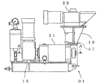
- FIG. 3 is an AA arrow view of the inside of the cover, the drive unit, the first roll, and the second roll shown in FIG. 2. It is a schematic diagram which shows the feeder screw in a hopper inside, and a shaft-integrated motor with a reduction gear.
- the drive unit 15 is provided with an output shaft 24.
- a first roll shaft 13 having a diameter larger than that of the output shaft 24 is connected to one end of the output shaft 24 coaxially.
- the second roll shaft 14 has the same configuration as that of the first roll shaft 13, and the steps 14a, 14b, 14c, and 14d have different diameters in order from the drive unit 15 side. And have.
- the diameter of the step part 14a and the step part 14c is smaller than the diameter of the step part 14b.
- the diameter of the step part 14d is smaller than the diameter of the step part 14c.
- a movable side bearing unit 17 including a pair of second bearings 26 that support the second roll shaft 14 is provided inside the cover 21.
- One of the two second bearings 26 is provided on the step portion 14a, and the other one is provided such that the end surface of the second bearing 26 is in contact with the boundary between the step portion 14b and the step portion 14c.
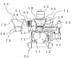
- the hopper 18 is arranged above the first roll 11 and the second roll 12, and the feeder screw 19 is provided in the hopper 18.
- a motor 23 with a speed reducer is provided on the upper part of the feeder screw 19. The motor 23 with speed reducer and the feeder screw 19 are connected so that the rotational driving force generated from the motor 23 with speed reducer is transmitted to the feeder screw 19.
- the hopper 18 is fixed to the cover 21 (FIG. 2), is formed integrally with the fixed hopper 32, and is movable and can be opened and closed in the horizontal direction.
- the movable hopper 33 is composed of a hopper 33 and is divided by a plane along the longitudinal direction of the fixed hopper 32 and the hopper 18. Further, the fixed hopper 32 and the movable hopper 33 in the hopper 18 are fixed by a link mechanism 34 (FIG. 3) so as to be opened and closed.
- the fixed hopper portion 32 includes a fixed side plane portion 55, and the movable hopper portion 33 includes a movable side plane portion 56.
- the link mechanism 34 includes a first arm 51 and a second arm 52, as shown in FIG.
- One end of the first arm 51 is connected to a plate-like fixed side extending portion 53 extending outward from one end of the fixed hopper portion 32 so as to be rotatable by a shaft.
- One end of the arm 52 is connected to be rotatable about an axis.
- the other end of the second arm 52 is connected to a plate-like movable side extending portion 54 extending outward from one end of the movable hopper portion 33 so as to be rotatable by a rotation shaft.
- the motor 23 with a speed reducer uses a shaft-integrated speed reducer motor, and includes a motor part 23a, a speed reducing part 23b, and a hollow shaft 23c.
- the shaft integrated type means that a shaft for transmitting torque to the feeder screw 19 is attached to the motor with a reduction gear.
- an orthogonal shaft integrated type motor with a speed reducer in which the rotation shaft of the motor portion 23a and the hollow shaft 23c are orthogonal to each other is used as the motor 23 with a speed reducer.
- a first gear 29 is provided on the step portion 13 a of the first roll shaft 13. The end surface of the first gear 29 is in contact with the boundary between the step portion 13a and the step portion 13b.
- a second gear 30 is provided on the step portion 14 a of the second roll shaft 14. The end surface of the second gear 30 is in contact with the boundary between the step portion 14a and the step portion 14b. The first gear 29 and the second gear 30 are engaged with each other.
- the fixed hopper 32 and the movable hopper 33 are fixed using bolts and nuts. More specifically, with the fixed side flat portion 55 in the fixed hopper 32 and the movable side flat portion 56 in the movable hopper 33 in contact with each other, the bolt and nut are passed through the fastening hole 71 and the fastening hole 72 to be fastened and fixed. As a result, the fixed hopper 32 and the movable hopper 33 are fixed.
- the hopper 18 When opening the hopper 18, such as when cleaning the inside of the hopper 18, it can be opened by the following procedure. First, the bolts and nuts fastened and fixed through the fastening holes 71 and 72 are removed. Next, the hand-held part 57 is pulled. The link mechanism 34 connects the fixed hopper portion 32 and the movable hopper portion 33, and the first arm 51 and the second arm 52 rotate as the hand holding portion 57 is pulled. Therefore, as shown in FIG. 1, the movable hopper 33 opens with respect to the fixed hopper 32.
- the fixed-side extension portion 53 is provided on the left side of the fixed hopper portion 32, and the method of opening the movable hopper portion 33 with respect to the fixed hopper portion 32 is left-opening.
- the fixed side extending portion 53 may be provided on the right side of the fixed hopper portion 32 so that the movable hopper portion 33 is opened to the fixed hopper portion 32 to the right.
- a motor with a reduction gear integrated with an orthogonal shaft is used as the motor 23 with a reduction gear.
- the rotation shaft of the motor portion 23a and the hollow shaft 23c have a parallel shaft integrated reduction device.
- a motor may be used.
Landscapes
- Engineering & Computer Science (AREA)
- Mechanical Engineering (AREA)
- Chemical & Material Sciences (AREA)
- Organic Chemistry (AREA)
- Chemical Kinetics & Catalysis (AREA)
- Press Drives And Press Lines (AREA)
- Filling Or Emptying Of Bunkers, Hoppers, And Tanks (AREA)
Abstract
Description
また、本発明は上述の詳細な説明により更に完全に理解できるであろう。しかしながら、詳細な説明および特定の実施例は、本発明の望ましい実施の形態であり、説明の目的のためにのみ記載されているものである。この詳細な説明から、種々の変更、改変が、当業者にとって明らかだからである。
出願人は、記載された実施の形態のいずれをも公衆に献上する意図はなく、開示された改変、代替案のうち、特許請求の範囲内に文言上含まれないかもしれないものも、均等論下での発明の一部とする。
本明細書あるいは請求の範囲の記載において、名詞及び同様な指示語の使用は、特に指示されない限り、または文脈によって明瞭に否定されない限り、単数および複数の両方を含むものと解釈すべきである。本明細書中で提供されたいずれの例示または例示的な用語(例えば、「等」)の使用も、単に本発明を説明し易くするという意図であるに過ぎず、特に請求の範囲に記載しない限り本発明の範囲に制限を加えるものではない。
11 第一ロール
12 第二ロール
13 第一ロール軸
14 第二ロール軸
15 駆動部
16 固定側軸受ユニット
17 可動側軸受ユニット
18 ホッパ
19 フィーダスクリュ
21 カバー
23 減速機付モータ
24 出力軸
25 第一軸受
26 第二軸受
29 第一歯車
30 第二歯車
31 油圧シリンダ
32 固定ホッパ部
33 可動ホッパ部
34 リンク機構
51 第一アーム
52 第二アーム
53 固定側延出部
54 可動側延出部
55 固定側平面部
56 可動側平面部
57 手持部
71 締結穴
72 締結穴
Claims (5)
- 第一ロール軸に固定される第一ロールと、
第二ロール軸に固定され、前記第一ロールと平行に配置されると共に、前記第一ロールと協動して原料を加圧固化してブリケットを圧縮成形する第二ロールと、
前記第一ロール軸及び前記第二ロール軸に回転駆動力を発生させる駆動部と、
前記第一ロール軸を軸支する固定側軸受ユニットと、
前記第二ロール軸を軸支すると共に、前記固定側軸受ユニットに対して前記第一ロールの回転軸に直交する方向に接近および離隔可能な可動側軸受ユニットと、
前記固定側軸受ユニット及び前記可動側軸受ユニットを覆うカバーと、
前記カバーに連結され、前記第一ロールおよび前記第二ロールの近傍の上方に位置するホッパと、
を備えるブリケットマシンにおいて、
前記ホッパは、前記カバーに固定された固定ホッパ部と、固定ホッパ部と一体的に形成されており、かつ水平方向に開閉可能である可動ホッパ部よりなり、前記可動ホッパ部は固定ホッパ部と、ホッパの縦軸方向に沿った面で分割されて形成されることを特徴とするブリケットマシン。 - 前記固定ホッパ部と前記可動ホッパ部はリンク機構によって開閉可能に固定されており、前記リンク機構の一端が前記固定ホッパ部の片側端に連結されると共に、前記リンク機構の他端が前記可動ホッパ部の片側端に連結されていることを特徴とする請求項1に記載のブリケットマシン。
- 前記固定ホッパ部と前記可動ホッパ部とは、双方の分割面同士を面合せしてボルトナットで固定したことを特徴とする請求項1又は請求項2に記載のブリケットマシン。
- 前記ホッパ内部には原料を前記第一ロールおよび前記第二ロールに供給するためのフィーダスクリュを備えることを特徴とする請求項1又は請求項2に記載のブリケットマシン。
- 前記フィーダスクリュは軸一体型の減速機付モータで駆動することを特徴とする請求項4に記載のブリケットマシン。
Priority Applications (2)
| Application Number | Priority Date | Filing Date | Title |
|---|---|---|---|
| CN201580000946.0A CN105392622B (zh) | 2014-06-23 | 2015-06-15 | 压块机 |
| JP2016529332A JP6455512B2 (ja) | 2014-06-23 | 2015-06-15 | ブリケットマシン |
Applications Claiming Priority (2)
| Application Number | Priority Date | Filing Date | Title |
|---|---|---|---|
| JP2014127879 | 2014-06-23 | ||
| JP2014-127879 | 2014-06-23 |
Publications (1)
| Publication Number | Publication Date |
|---|---|
| WO2015198902A1 true WO2015198902A1 (ja) | 2015-12-30 |
Family
ID=54937992
Family Applications (1)
| Application Number | Title | Priority Date | Filing Date |
|---|---|---|---|
| PCT/JP2015/067192 Ceased WO2015198902A1 (ja) | 2014-06-23 | 2015-06-15 | ブリケットマシン |
Country Status (3)
| Country | Link |
|---|---|
| JP (1) | JP6455512B2 (ja) |
| CN (1) | CN105392622B (ja) |
| WO (1) | WO2015198902A1 (ja) |
Cited By (1)
| Publication number | Priority date | Publication date | Assignee | Title |
|---|---|---|---|---|
| CN110774418A (zh) * | 2019-11-07 | 2020-02-11 | 邵阳金拓科技开发有限公司 | 一种脱硫石膏压球机脱模装置 |
Families Citing this family (3)
| Publication number | Priority date | Publication date | Assignee | Title |
|---|---|---|---|---|
| CN106553374A (zh) * | 2016-11-15 | 2017-04-05 | 长沙新气象自动化技术有限公司 | 一种压力自适应压球机 |
| CN110341232A (zh) * | 2019-08-22 | 2019-10-18 | 刘卫平 | 一种拌煤机 |
| CN115320162B (zh) * | 2022-04-22 | 2023-04-28 | 南方石墨新材料有限公司 | 一种石墨压球机 |
Citations (4)
| Publication number | Priority date | Publication date | Assignee | Title |
|---|---|---|---|---|
| JPH11123598A (ja) * | 1997-10-21 | 1999-05-11 | Hosokawa Micron Corp | ブリケッティングマシン及びブリケットの製造方法 |
| JP2001009834A (ja) * | 1999-06-30 | 2001-01-16 | Nakamura Kagakukogyo Co Ltd | プラスチックペレット乾燥装置用ホッパドライヤ |
| JP2004237296A (ja) * | 2003-02-04 | 2004-08-26 | Freunt Ind Co Ltd | 乾式造粒装置 |
| JP2014050844A (ja) * | 2011-02-28 | 2014-03-20 | Sintokogio Ltd | ブリケットマシン |
Family Cites Families (2)
| Publication number | Priority date | Publication date | Assignee | Title |
|---|---|---|---|---|
| CN201020860Y (zh) * | 2007-03-10 | 2008-02-13 | 李瑞平 | 高压热态压块机 |
| CN201735376U (zh) * | 2010-07-02 | 2011-02-09 | 国营第一二一厂 | 一种辊压机 |
-
2015
- 2015-06-15 CN CN201580000946.0A patent/CN105392622B/zh active Active
- 2015-06-15 JP JP2016529332A patent/JP6455512B2/ja active Active
- 2015-06-15 WO PCT/JP2015/067192 patent/WO2015198902A1/ja not_active Ceased
Patent Citations (4)
| Publication number | Priority date | Publication date | Assignee | Title |
|---|---|---|---|---|
| JPH11123598A (ja) * | 1997-10-21 | 1999-05-11 | Hosokawa Micron Corp | ブリケッティングマシン及びブリケットの製造方法 |
| JP2001009834A (ja) * | 1999-06-30 | 2001-01-16 | Nakamura Kagakukogyo Co Ltd | プラスチックペレット乾燥装置用ホッパドライヤ |
| JP2004237296A (ja) * | 2003-02-04 | 2004-08-26 | Freunt Ind Co Ltd | 乾式造粒装置 |
| JP2014050844A (ja) * | 2011-02-28 | 2014-03-20 | Sintokogio Ltd | ブリケットマシン |
Cited By (1)
| Publication number | Priority date | Publication date | Assignee | Title |
|---|---|---|---|---|
| CN110774418A (zh) * | 2019-11-07 | 2020-02-11 | 邵阳金拓科技开发有限公司 | 一种脱硫石膏压球机脱模装置 |
Also Published As
| Publication number | Publication date |
|---|---|
| CN105392622B (zh) | 2018-06-15 |
| CN105392622A (zh) | 2016-03-09 |
| JP6455512B2 (ja) | 2019-01-23 |
| JPWO2015198902A1 (ja) | 2017-04-20 |
Similar Documents
| Publication | Publication Date | Title |
|---|---|---|
| JP6455512B2 (ja) | ブリケットマシン | |
| US9101938B2 (en) | Pre-grinder or pre-shredder | |
| CN102112234B (zh) | 辊磨机 | |
| KR101765904B1 (ko) | 공작물을 파인 블랭킹, 포밍 및/또는 스탬핑하기 위한 기계 프레스 | |
| CN202278266U (zh) | 单蜗轮双蜗杆双电机驱动蜗轮蜗杆副 | |
| CN107984295A (zh) | 一种机床用防护装置 | |
| CN202506427U (zh) | 一种对辊硅铁破碎机 | |
| JP2013000732A (ja) | ジョークラッシャ | |
| CN103252267B (zh) | 一种双轴差动物料破碎机 | |
| CN201693106U (zh) | 一种轧延成型机 | |
| JP2014050844A (ja) | ブリケットマシン | |
| JP6614144B2 (ja) | 片持ち式ブリケットマシン | |
| CN210281400U (zh) | 一种数控打点的加工用设备 | |
| CN201580043U (zh) | 一体式圆网印花机网头传动装置 | |
| CN104879393B (zh) | 一种结构简单的安全联轴器 | |
| JP2012152205A (ja) | 小型チョッパの伝動装置 | |
| CN103846320A (zh) | 三辊传动卷板机 | |
| CN217774723U (zh) | 一种石灰粉除杂用滚筒筛 | |
| CA3046409C (en) | PELLET MANUFACTURING DEVICE | |
| CN201723651U (zh) | 自调式焊接滚轮架钳型架的传动装置 | |
| CN220923241U (zh) | 橡胶挤出机喂料机构的傍压装置 | |
| JP5389077B2 (ja) | 乗客コンベア減速機の軸受抜き雇装置 | |
| CN104895944B (zh) | 多功能复合机床动力切换装置 | |
| CN212468509U (zh) | 一种便于下料的化工用离心机 | |
| CN214490389U (zh) | 一种搪瓷搅拌器机械密封在线更换装置 |
Legal Events
| Date | Code | Title | Description |
|---|---|---|---|
| WWE | Wipo information: entry into national phase |
Ref document number: 201580000946.0 Country of ref document: CN |
|
| 121 | Ep: the epo has been informed by wipo that ep was designated in this application |
Ref document number: 15810855 Country of ref document: EP Kind code of ref document: A1 |
|
| ENP | Entry into the national phase |
Ref document number: 2016529332 Country of ref document: JP Kind code of ref document: A |
|
| NENP | Non-entry into the national phase |
Ref country code: DE |
|
| 122 | Ep: pct application non-entry in european phase |
Ref document number: 15810855 Country of ref document: EP Kind code of ref document: A1 |