WO2015198776A1 - 車両の電源装置 - Google Patents
車両の電源装置 Download PDFInfo
- Publication number
- WO2015198776A1 WO2015198776A1 PCT/JP2015/065052 JP2015065052W WO2015198776A1 WO 2015198776 A1 WO2015198776 A1 WO 2015198776A1 JP 2015065052 W JP2015065052 W JP 2015065052W WO 2015198776 A1 WO2015198776 A1 WO 2015198776A1
- Authority
- WO
- WIPO (PCT)
- Prior art keywords
- capacitor
- internal resistance
- power supply
- voltage
- resistance value
- Prior art date
- Legal status (The legal status is an assumption and is not a legal conclusion. Google has not performed a legal analysis and makes no representation as to the accuracy of the status listed.)
- Ceased
Links
Images


Classifications
-
- B—PERFORMING OPERATIONS; TRANSPORTING
- B60—VEHICLES IN GENERAL
- B60R—VEHICLES, VEHICLE FITTINGS, OR VEHICLE PARTS, NOT OTHERWISE PROVIDED FOR
- B60R16/00—Electric or fluid circuits specially adapted for vehicles and not otherwise provided for; Arrangement of elements of electric or fluid circuits specially adapted for vehicles and not otherwise provided for
- B60R16/02—Electric or fluid circuits specially adapted for vehicles and not otherwise provided for; Arrangement of elements of electric or fluid circuits specially adapted for vehicles and not otherwise provided for electric constitutive elements
- B60R16/03—Electric or fluid circuits specially adapted for vehicles and not otherwise provided for; Arrangement of elements of electric or fluid circuits specially adapted for vehicles and not otherwise provided for electric constitutive elements for supply of electrical power to vehicle subsystems or for
-
- H—ELECTRICITY
- H01—ELECTRIC ELEMENTS
- H01M—PROCESSES OR MEANS, e.g. BATTERIES, FOR THE DIRECT CONVERSION OF CHEMICAL ENERGY INTO ELECTRICAL ENERGY
- H01M10/00—Secondary cells; Manufacture thereof
- H01M10/42—Methods or arrangements for servicing or maintenance of secondary cells or secondary half-cells
- H01M10/48—Accumulators combined with arrangements for measuring, testing or indicating the condition of cells, e.g. the level or density of the electrolyte
-
- F—MECHANICAL ENGINEERING; LIGHTING; HEATING; WEAPONS; BLASTING
- F02—COMBUSTION ENGINES; HOT-GAS OR COMBUSTION-PRODUCT ENGINE PLANTS
- F02D—CONTROLLING COMBUSTION ENGINES
- F02D29/00—Controlling engines, such controlling being peculiar to the devices driven thereby, the devices being other than parts or accessories essential to engine operation, e.g. controlling of engines by signals external thereto
- F02D29/02—Controlling engines, such controlling being peculiar to the devices driven thereby, the devices being other than parts or accessories essential to engine operation, e.g. controlling of engines by signals external thereto peculiar to engines driving vehicles; peculiar to engines driving variable pitch propellers
-
- F—MECHANICAL ENGINEERING; LIGHTING; HEATING; WEAPONS; BLASTING
- F02—COMBUSTION ENGINES; HOT-GAS OR COMBUSTION-PRODUCT ENGINE PLANTS
- F02N—STARTING OF COMBUSTION ENGINES; STARTING AIDS FOR SUCH ENGINES, NOT OTHERWISE PROVIDED FOR
- F02N11/00—Starting of engines by means of electric motors
- F02N11/08—Circuits specially adapted for starting of engines
-
- H—ELECTRICITY
- H02—GENERATION; CONVERSION OR DISTRIBUTION OF ELECTRIC POWER
- H02J—ELECTRIC POWER NETWORKS; CIRCUIT ARRANGEMENTS OR SYSTEMS FOR SUPPLYING OR DISTRIBUTING ELECTRIC POWER; SYSTEMS FOR STORING ELECTRIC ENERGY
- H02J7/00—Circuit arrangements for charging or discharging batteries or for supplying loads from batteries
-
- Y—GENERAL TAGGING OF NEW TECHNOLOGICAL DEVELOPMENTS; GENERAL TAGGING OF CROSS-SECTIONAL TECHNOLOGIES SPANNING OVER SEVERAL SECTIONS OF THE IPC; TECHNICAL SUBJECTS COVERED BY FORMER USPC CROSS-REFERENCE ART COLLECTIONS [XRACs] AND DIGESTS
- Y02—TECHNOLOGIES OR APPLICATIONS FOR MITIGATION OR ADAPTATION AGAINST CLIMATE CHANGE
- Y02E—REDUCTION OF GREENHOUSE GAS [GHG] EMISSIONS, RELATED TO ENERGY GENERATION, TRANSMISSION OR DISTRIBUTION
- Y02E60/00—Enabling technologies; Technologies with a potential or indirect contribution to GHG emissions mitigation
- Y02E60/10—Energy storage using batteries
-
- Y—GENERAL TAGGING OF NEW TECHNOLOGICAL DEVELOPMENTS; GENERAL TAGGING OF CROSS-SECTIONAL TECHNOLOGIES SPANNING OVER SEVERAL SECTIONS OF THE IPC; TECHNICAL SUBJECTS COVERED BY FORMER USPC CROSS-REFERENCE ART COLLECTIONS [XRACs] AND DIGESTS
- Y02—TECHNOLOGIES OR APPLICATIONS FOR MITIGATION OR ADAPTATION AGAINST CLIMATE CHANGE
- Y02T—CLIMATE CHANGE MITIGATION TECHNOLOGIES RELATED TO TRANSPORTATION
- Y02T10/00—Road transport of goods or passengers
- Y02T10/10—Internal combustion engine [ICE] based vehicles
- Y02T10/40—Engine management systems
Definitions
- This invention relates to a power supply device for a vehicle.
- a power supply device including a capacitor in addition to a normal auxiliary battery has become widespread.
- a DC / DC converter is provided between an alternator, an auxiliary battery, or the like and a capacitor in order to adjust the voltage.
- Patent Document 1 describes a method for determining the internal resistance of a capacitor.
- the conventional technology uses a constant idling stop control regardless of the internal resistance value of the capacitor, so that there is a possibility that restart from idling stop may not be possible if the internal resistance value of the capacitor increases.
- the voltage applied to the starter decreases, which may make it impossible to restart the internal combustion engine.
- the present invention has been made to solve such a problem, and provides a vehicle power supply device that can avoid an event that it is impossible to restart from an idling stop regardless of the internal resistance value of the capacitor.
- the purpose is to provide.
- the power supply device for a vehicle is a power supply device for a vehicle, and includes a secondary battery, an auxiliary device and a DC / DC converter, a secondary battery and an auxiliary device connected in parallel to the secondary battery.
- a capacitor connected via a DC / DC converter and a starter connected to the capacitor, the DC / DC converter includes an internal resistance value measuring means for measuring the internal resistance value of the capacitor, and a power source
- the apparatus changes the control related to the idling stop of the internal combustion engine that is started by using the starter according to the internal resistance value of the capacitor.
- the control related to the idling stop of the internal combustion engine is changed according to the internal resistance value of the capacitor.
- the control related to the idling stop of the internal combustion engine is changed according to the internal resistance value of the capacitor, so that the restart from the idling stop can be performed regardless of the internal resistance value of the capacitor. It is possible to avoid the phenomenon of being impossible.
- the idling stop itself is avoided by prohibiting the idling stop, so that it is also possible to avoid the event that restart from the idling stop cannot be performed.
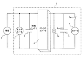
- FIG. 1 is a diagram showing a configuration including a power supply device 1 according to Embodiment 1 of the present invention.
- the power supply device 1 is a power supply device for a vehicle and supplies power to a load mounted on the vehicle.
- the load is, for example, the auxiliary machine 2.
- the power supply device 1 includes an alternator 3, an auxiliary battery 4, a capacitor 5, a DC / DC converter 6, and a starter 7.
- the alternator 3 functions as a generator.
- the auxiliary battery 4 is a secondary battery, for example, a lead battery.
- the capacitor 5 is, for example, an electric double layer capacitor (EDLC).
- At least a part of the load (auxiliary machine 2 in the example of FIG. 1), the alternator 3, and the DC / DC converter 6 are connected in parallel to the auxiliary battery 4.
- Capacitor 5 is connected to auxiliary battery 4 and auxiliary machine 2 via DC / DC converter 6, and starter 7 is connected to capacitor 5 via starter activation switch 7a.
- the capacitor 5 and the starter 7 are connected in parallel to the auxiliary machine 2, the alternator 3 and the auxiliary battery 4 via the DC / DC converter 6.
- the DC / DC converter 6 has a function of converting the voltage of power supplied from at least one of the alternator 3 and the auxiliary battery 4 and supplying the voltage to the capacitor 5. . Further, the DC / DC converter 6 has a function of converting the voltage of the electric power supplied from the capacitor 5 and supplying it to at least one of the auxiliary machine 2, the alternator 3 and the auxiliary battery 4.
- auxiliary machine 2 a part of the load (auxiliary machine 2) is directly connected to the auxiliary battery 4 and connected to the capacitor 5 via the DC / DC converter 6. For this reason, when the auxiliary machine 2 is supplied with power from the auxiliary battery 4, the voltage of the auxiliary battery 4 is applied as it is. On the other hand, when the auxiliary machine 2 is supplied with electric power from the capacitor 5, the voltage can be controlled via the DC / DC converter 6.
- the starter 7 is supplied with electric power from the capacitor 5 and starts an internal combustion engine (not shown).
- the power supply device 1 includes a control device that controls the operation of the power supply device 1.
- the control device is constituted by, for example, a computer (for example, a microprocessor or the like) that includes a calculation unit and a storage unit.
- a computer for example, a microprocessor or the like
- the control of the alternator 3, the auxiliary battery 4, the capacitor 5, and the DC / DC converter 6 is executed by this control device.
- the computer controls only the DC / DC converter 6.
- the DC / DC converter 6 includes internal resistance value measuring means for measuring the internal resistance value of the capacitor 5.
- the internal resistance value measuring means can be configured using, for example, a voltage measuring means 6a.
- Such internal resistance value measuring means measures the internal resistance value based on, for example, a change in voltage during charging due to a constant current.
- FIG. 2 is a diagram for explaining an example of the principle of measuring the internal resistance value of the capacitor 5 by the internal resistance value measuring means configurable using the voltage measuring means.
- the control device charges the capacitor 5 with a constant current (current value is I).
- the voltage V2 at time t1 after the elapse of the predetermined time T1 from the charging start time t0 is measured, and further the voltage V3 at time t2 after the elapse of the predetermined time T2 is measured.
- the voltage V1 at time t0 + 0 immediately after the start of charging is calculated.
- V1 V2-a ⁇ (t1-t0).
- the configuration of the internal resistance value measuring means and the internal resistance value measuring method can be realized using any other known technique. Further, information indicating the internal resistance value R (for example, a value of R or a value indicating a range to which R belongs) may be notified to the control device or the like.
- the power supply device 1 When the vehicle is decelerated, the power supply device 1 generates power with the alternator 3. At least a part of the generated electric power charges the capacitor 5 after adjusting the voltage and current by the DC / DC converter 6.
- the power supply device 1 When the power supply device 1 charges the capacitor 5, the internal resistance value of the capacitor 5 is measured by the internal resistance value measuring means. Then, the power supply device 1 changes the control related to the idling stop of the internal combustion engine according to the internal resistance value of the capacitor 5.
- FIG. 3 is a diagram showing an example of control related to idling stop of the internal combustion engine, which is changed according to the internal resistance value of the capacitor 5.
- the content of the control is changed according to a threshold value related to the internal resistance value of the capacitor 5.
- a first threshold value R1 and a second threshold value R2 are shown as two threshold values (where 0 ⁇ R2 ⁇ R1).
- the power supply device 1 when the internal resistance value of the capacitor 5 exceeds the first threshold value R1, the power supply device 1 performs control to prohibit idling stop. For example, even if the internal combustion engine is idling for a long time, the internal combustion engine is not stopped. Here, if the internal resistance value becomes too large, the restart of the internal combustion engine may be impossible, but the value of the first threshold value R1 is set to a value belonging to a range in which the internal combustion engine can be restarted. If this is the case, the internal combustion engine will not stop in a state where the internal resistance has become so large that restarting is impossible.
- Vth is the lower limit voltage value at which the internal combustion engine can be started, for example, when the internal resistance value is R1, and represents the lower limit of the voltage value at which the internal combustion engine can be started (or restarted).
- Vth does not have to be 10 V, and can be appropriately determined by a person skilled in the art so as to be suitable when the internal resistance value of the capacitor 5 exceeds the second threshold value R2 and is less than the first threshold value R1. Further, the value of Vth does not necessarily correspond to the actual lower limit voltage value at which the internal combustion engine can be started, and may be set including a certain margin value, for example.
- the control for setting the voltage of the capacitor 5 during idling stop to Vth or more may be realized in any way, but for example, the following two specific controls are possible.
- the first specific control when the voltage of the capacitor 5 is equal to or lower than Vth, it is possible to control to prohibit the supply of power from the capacitor 5 to the auxiliary machine 2.
- the time when the voltage of the capacitor 5 becomes Vth or less (or when it becomes equal to Vth) the time when the voltage of the capacitor 5 becomes Vth or less (or when it becomes equal to Vth) ),
- the DC / DC converter 6 is shut down, and the supply of power from the capacitor 5 to the auxiliary machine 2 is stopped.
- the supply of power to the auxiliary machine 2 immediately after that is performed from the auxiliary battery 4, for example.
- the capacitor 5 can be charged from the alternator 3 or the auxiliary battery 4 via the DC / DC converter 6.
- the voltage of the capacitor 5 during idling stop is maintained at Vth or higher (in practice, regardless of whether idling is stopped).
- the voltage of the capacitor 5 becomes less than Vth, it can be raised to Vth or more by charging the capacitor 5.
- the capacitor 5 can be charged from the alternator 3 or the auxiliary battery 4 via the DC / DC converter 6.
- the voltage of the capacitor 5 during idling stop is maintained at Vth or higher by the second specific control.
- the voltage of the capacitor 5 becomes less than Vth, it can be raised to Vth or more by charging the capacitor 5.
- the first specific control and the second specific control may be combined. For example, when the voltage of the capacitor 5 becomes equal to or lower than Vth during idling stop, it is possible to prohibit the supply of electric power from the capacitor 5 to the auxiliary machine 2 and to start the internal combustion engine.
- the value of the second threshold value R2 is set so as to belong to a range in which the internal combustion engine can be restarted when the voltage of the capacitor 5 is Vth. If this is done, the internal combustion engine will not stop in a state where the voltage of the capacitor 5 is lowered so that restarting is impossible.
- the power supply device 1 has the capacitor 5 connected to the auxiliary battery.
- the power may be controlled to be supplied to the auxiliary machine 2 with priority over 4.
- the internal resistance value exceeds the second threshold R2 and is less than the first threshold R1
- the voltage of the capacitor 5 exceeds Vth
- power can be supplied from both the auxiliary battery 4 and the capacitor 5 to the auxiliary machine 2
- the auxiliary battery 4 supplies power to the auxiliary machine 2.
- the power may be supplied to the auxiliary machine 2 from the capacitor 5 without being supplied.
- the power supply device 1 when the internal resistance value of the capacitor 5 is less than the second threshold value R2, the power supply device 1 performs normal control. For example, during normal driving (for example, when the vehicle is not accelerating or decelerating), the alternator 3 is stopped and the electric charge stored in the capacitor 5 is adjusted after the voltage is adjusted via the DC / DC converter 6. To the machine 2 and the auxiliary battery 4. Further, as the normal control, any known capacitor control in the vehicle power supply device may be included. If the value of the second threshold value R2 is set to a value belonging to a range in which the internal combustion engine can be restarted regardless of the voltage of the capacitor 5, the internal combustion engine can always be restarted.
- the internal resistance value measuring means may measure the internal resistance value of the capacitor 5 based on a change in voltage during charging instead of charging.
- the control is changed based on the two threshold values R1 and R2, but either one of the threshold values may be used.
- the threshold value may be only the second threshold value R2, normal control may be performed when the internal resistance value is less than R2, and idling stop may be prohibited when the internal resistance value exceeds R2.
- the value of the lower limit voltage value at which the internal combustion engine can be started may be changed stepwise in the interval between the threshold values.
- the lower limit voltage value Vth is the lower limit of the voltage value at which the internal combustion engine can be started (or restarted) when the internal resistance value is R1, but the internal combustion engine start (or The lower limit of the voltage value that can be restarted) may be set to the lower limit voltage value Vth, and the voltage of the capacitor 5 may be controlled to be equal to or higher than Vth.
- the lower limit voltage value Vth is a fixed value, but may be changed dynamically.
- the control device may determine the lower limit voltage value Vth based on the internal resistance value R. This determination may be made by mapping based on a predefined table or by assignment to a predefined function. Further, the control device may determine the lower limit voltage value Vth based on another measured value in addition to or instead of the internal resistance value R.
Landscapes
- Engineering & Computer Science (AREA)
- Chemical & Material Sciences (AREA)
- Mechanical Engineering (AREA)
- Chemical Kinetics & Catalysis (AREA)
- Electrochemistry (AREA)
- General Chemical & Material Sciences (AREA)
- Manufacturing & Machinery (AREA)
- Combustion & Propulsion (AREA)
- General Engineering & Computer Science (AREA)
- Power Engineering (AREA)
- Charge And Discharge Circuits For Batteries Or The Like (AREA)
- Direct Current Feeding And Distribution (AREA)
- Secondary Cells (AREA)
- Control Of Vehicle Engines Or Engines For Specific Uses (AREA)
Abstract
キャパシタの内部抵抗値に関わらず、アイドリングストップからの再始動ができないという事象を回避することができる、車両の電源装置を提供する。 車両の電源装置1は、補機バッテリ4と、補機バッテリ4に対して並列に接続される、補機2およびDC/DCコンバータ6と、補機バッテリ4および補機2に対して、DC/DCコンバータ6を介して接続されるキャパシタ5と、キャパシタ5に接続されるスタータ7とを備える。DC/DCコンバータ6は、キャパシタ5の内部抵抗値を測定する内部抵抗値測定手段を備え、電源装置1は、キャパシタ5の内部抵抗値に応じ、スタータ7を用いて始動される内燃機関のアイドリングストップに係る制御を変更する。
Description
この発明は車両の電源装置に関する。
車両の減速時のエネルギーを回収するため(回生機能)、通常の補機バッテリの他にキャパシタを備えた電源装置が普及してきている。このような電源装置では、電圧を調整するために、オルタネータや補機バッテリなどとキャパシタとの間に、DC/DCコンバータが設けられる。
このような電源装置において、アイドリングストップにより停止した内燃機関の再始動のためにスタータに電力を供給する際には、二次電池でなくキャパシタの電力を用いる制御が行われる場合がある。
特許文献1には、キャパシタの内部抵抗を判定する方法が記載されている。
特許文献1には、キャパシタの内部抵抗を判定する方法が記載されている。
従来の技術では、キャパシタの内部抵抗値に関わらず一定のアイドリングストップ制御を用いるので、キャパシタの内部抵抗値が増加するとアイドリングストップからの再始動ができなくなるおそれがあるという問題があった。
たとえば、キャパシタ温度低下やキャパシタ劣化等によりキャパシタの内部抵抗が増加すると、スタータに印加される電圧が低下し、このため内燃機関の再始動ができなくなる場合がある。
この発明はこのような問題点を解消するためになされたものであり、キャパシタの内部抵抗値に関わらず、アイドリングストップからの再始動ができないという事象を回避することができる、車両の電源装置を提供することを目的とする。
この発明に係る車両の電源装置は、車両の電源装置であって、二次電池と、二次電池に対して並列に接続される、補機およびDC/DCコンバータと、二次電池および補機に対して、DC/DCコンバータを介して接続されるキャパシタと、キャパシタに接続されるスタータとを備え、DC/DCコンバータは、キャパシタの内部抵抗値を測定する内部抵抗値測定手段を備え、電源装置は、キャパシタの内部抵抗値に応じ、スタータを用いて始動される内燃機関のアイドリングストップに係る制御を変更する。
このような構成によれば、キャパシタの内部抵抗値に応じ、内燃機関のアイドリングストップに係る制御が変更される。
この発明に係る車両の電源装置によれば、キャパシタの内部抵抗値に応じて内燃機関のアイドリングストップに係る制御が変更されるので、キャパシタの内部抵抗値に関わらず、アイドリングストップからの再始動ができないという事象を回避することができる。
たとえば、内部抵抗がある程度増加した場合にはアイドリングストップを禁止することにより、アイドリングストップそのものを回避するので、アイドリングストップからの再始動ができないという事象についても回避することができる。
以下、この発明の実施の形態を添付図面に基づいて説明する。
実施の形態1.
図1は、この発明の実施の形態1に係る電源装置1を含む構成を示す図である。
電源装置1は車両の電源装置であり、車両に搭載される負荷に電力を供給する。負荷は、たとえば補機2である。
実施の形態1.
図1は、この発明の実施の形態1に係る電源装置1を含む構成を示す図である。
電源装置1は車両の電源装置であり、車両に搭載される負荷に電力を供給する。負荷は、たとえば補機2である。
電源装置1は、オルタネータ3、補機バッテリ4、キャパシタ5、DC/DCコンバータ6およびスタータ7を備える。オルタネータ3は、発電機として機能する。補機バッテリ4は二次電池であり、たとえば鉛バッテリである。キャパシタ5はたとえば電気二重層キャパシタ(EDLC)である。
負荷のうち少なくとも一部(図1の例では補機2)と、オルタネータ3と、DC/DCコンバータ6とは、補機バッテリ4に対して並列に接続される。また、キャパシタ5は、補機バッテリ4および補機2に対して、DC/DCコンバータ6を介して接続され、スタータ7はスタータ起動スイッチ7aを介してキャパシタ5に接続される。とくに、本実施形態では、キャパシタ5およびスタータ7は、補機2、オルタネータ3および補機バッテリ4に対し、DC/DCコンバータ6を介して、並列に接続される。
DC/DCコンバータ6の内部構成はとくに説明しないが、DC/DCコンバータ6は、オルタネータ3および補機バッテリ4の少なくとも一方から供給される電力の電圧を変換し、キャパシタ5に供給する機能を有する。また、DC/DCコンバータ6は、キャパシタ5から供給される電力の電圧を変換し、補機2、オルタネータ3および補機バッテリ4のうち少なくとも1つに供給する機能を有する。
言い換えると、負荷の一部(補機2)は、補機バッテリ4には直接的に接続され、キャパシタ5にはDC/DCコンバータ6を介して接続される。このため、補機2が補機バッテリ4から電力の供給を受ける場合には、補機バッテリ4の電圧がそのまま印加されることになる。一方、補機2がキャパシタ5から電力の供給を受ける場合には、DC/DCコンバータ6を介して電圧の制御が可能である。
スタータ7は、キャパシタ5から電力の供給を受けて内燃機関(図示せず)の始動を行う。
また、とくに図示しないが、電源装置1は、電源装置1の動作を制御する制御装置を備える。制御装置はたとえば演算手段および記憶手段を備えるコンピュータ(たとえばマイクロプロセッサ等)によって構成される。また、以下ではとくに明記しないが、オルタネータ3、補機バッテリ4、キャパシタ5およびDC/DCコンバータ6の制御は、この制御装置により実行される。コンピュータが制御するのはDC/DCコンバータ6のみとなる。
さらに、DC/DCコンバータ6は、キャパシタ5の内部抵抗値を測定するための内部抵抗値測定手段を備える。内部抵抗値測定手段は、たとえば電圧測定手段6aを用いて構成することができる。このような内部抵抗値測定手段は、内部抵抗値を、たとえば定電流による充電中の電圧の変化に基づいて測定する。
図2は、電圧測定手段を用いて構成可能な内部抵抗値測定手段による、キャパシタ5の内部抵抗値の測定原理の一例を説明する図である。
まず、制御装置は、キャパシタ5への充電を、定電流(電流値をIとする)により行う。充電開始時刻t0から所定時間T1経過後の時刻t1における電圧V2を測定し、さらに所定時間T2経過後の時刻t2における電圧V3を測定する。その後、時刻t1からt2までの電圧の傾きaを、a=(V3-V2)/(t2-t1)として算出する。その後、傾きaに基づき、充電開始直後の時刻t0+0における電圧V1を算出する。たとえばV1=V2-a・(t1-t0)である。その後、電圧V1と、充電開始直前の時刻t0-0における電圧V0とに基づき、内部抵抗値Rを算出する。たとえばR=(V1-V0)/Iである。
まず、制御装置は、キャパシタ5への充電を、定電流(電流値をIとする)により行う。充電開始時刻t0から所定時間T1経過後の時刻t1における電圧V2を測定し、さらに所定時間T2経過後の時刻t2における電圧V3を測定する。その後、時刻t1からt2までの電圧の傾きaを、a=(V3-V2)/(t2-t1)として算出する。その後、傾きaに基づき、充電開始直後の時刻t0+0における電圧V1を算出する。たとえばV1=V2-a・(t1-t0)である。その後、電圧V1と、充電開始直前の時刻t0-0における電圧V0とに基づき、内部抵抗値Rを算出する。たとえばR=(V1-V0)/Iである。
なお、内部抵抗値測定手段の構成および内部抵抗値の測定方法は、他の任意の公知技術を用いて実現可能である。また、内部抵抗値Rを表す情報(たとえばRの値、またはRが属する範囲を表す値)を、制御装置等に通知してもよい。
次に、実施の形態1に係る電源装置1の動作を説明する。
車両の減速時には、電源装置1は、オルタネータ3により発電を行う。発生した電力の少なくとも一部は、DC/DCコンバータ6で電圧および電流を調整した後にキャパシタ5に充電する。
車両の減速時には、電源装置1は、オルタネータ3により発電を行う。発生した電力の少なくとも一部は、DC/DCコンバータ6で電圧および電流を調整した後にキャパシタ5に充電する。
電源装置1は、キャパシタ5への充電を行う際に、内部抵抗値測定手段によりキャパシタ5の内部抵抗値を測定する。そして、電源装置1は、キャパシタ5の内部抵抗値に応じ、内燃機関のアイドリングストップに係る制御を変更する。
図3は、キャパシタ5の内部抵抗値に応じて変更される、内燃機関のアイドリングストップに係る制御の例を示す図である。図3の例では、制御の内容は、キャパシタ5の内部抵抗値に関する閾値に応じて変更される。図3の例では、2つの閾値として、第1閾値R1と、第2閾値R2とが示されている(ただし0<R2<R1である)。
図3に示すように、キャパシタ5の内部抵抗値が第1閾値R1を超える場合には、電源装置1はアイドリングストップを禁止する制御を行う。たとえば、内燃機関が長時間アイドリング状態であっても、内燃機関を停止させない。ここで、内部抵抗値が大きくなりすぎると内燃機関の再始動が不可能となるおそれがあるが、第1閾値R1の値を、内燃機関の再始動が可能な範囲に属する値に設定しておけば、再始動が不可能なほど内部抵抗が大きくなった状態で内燃機関が停止してしまうことがない。
また、キャパシタ5の内部抵抗値が第2閾値R2を超え第1閾値R1未満である場合には、アイドリングストップ中のキャパシタ5の電圧を、所定の下限電圧値Vth以上とする制御を行う。このVthは、たとえば内部抵抗値がR1の場合に内燃機関の始動(または再始動)が可能な電圧値の下限を表す内燃機関始動可能下限電圧値であり、本実施形態では例として10Vとする。
Vthの値は10Vでなくともよく、キャパシタ5の内部抵抗値が第2閾値R2を超え第1閾値R1未満である場合によく適合するよう、当業者が適宜決定可能である。また、Vthの値は必ずしも実際の内燃機関始動可能下限電圧値に対応する必要はなく、たとえばある程度の余裕値を含んで設定されてもよい。
アイドリングストップ中のキャパシタ5の電圧をVth以上とする制御は、どのように実現されてもよいが、たとえば次の2通りの具体的制御が可能である。
第1の具体的制御として、キャパシタ5の電圧がVth以下である場合には、キャパシタ5から補機2への電力の供給を禁止する制御とすることができる。たとえば、キャパシタ5から補機2に電力が供給され、これに伴ってキャパシタ5の電圧が低下してゆく場合には、キャパシタ5の電圧がVth以下となった時点(またはVthに等しくなった時点)で、DC/DCコンバータ6をシャットダウンし、キャパシタ5から補機2への電力の供給を停止する。その直後の補機2への電力の供給は、たとえば補機バッテリ4から行われることになる。なお、キャパシタ5の電圧がVth以下となった場合でも、キャパシタ5への充電は、オルタネータ3または補機バッテリ4からDC/DCコンバータ6を介して行うことができる。
第1の具体的制御として、キャパシタ5の電圧がVth以下である場合には、キャパシタ5から補機2への電力の供給を禁止する制御とすることができる。たとえば、キャパシタ5から補機2に電力が供給され、これに伴ってキャパシタ5の電圧が低下してゆく場合には、キャパシタ5の電圧がVth以下となった時点(またはVthに等しくなった時点)で、DC/DCコンバータ6をシャットダウンし、キャパシタ5から補機2への電力の供給を停止する。その直後の補機2への電力の供給は、たとえば補機バッテリ4から行われることになる。なお、キャパシタ5の電圧がVth以下となった場合でも、キャパシタ5への充電は、オルタネータ3または補機バッテリ4からDC/DCコンバータ6を介して行うことができる。
このように、第1の具体的制御により、アイドリングストップ中のキャパシタ5の電圧が(実際には、アイドリングストップ中であるか否かに関わらず)Vth以上に保たれる。なお、キャパシタ5の電圧がVth未満となった場合には、キャパシタ5への充電によりVth以上に上昇させることが可能である。
また、第2の具体的制御として、アイドリングストップ中にキャパシタ5の電圧がVth以下となった場合に、内燃機関を始動する制御とすることができる。たとえば、内燃機関がアイドリングストップ中である間に、キャパシタ5から補機2に電力が供給されてキャパシタ5の電圧が低下し、キャパシタ5の電圧がVth以下となった時点(またはVthに等しくなった時点)で、キャパシタ5からスタータ7に電力を供給して内燃機関を始動させる。その直後の補機2への電力の供給は、たとえば補機バッテリ4から行われることになる。なお、キャパシタ5の電圧がVth以下となった場合でも、キャパシタ5への充電は、オルタネータ3または補機バッテリ4からDC/DCコンバータ6を介して行うことができる。
このように、第2の具体的制御により、アイドリングストップ中のキャパシタ5の電圧がVth以上に保たれる。なお、キャパシタ5の電圧がVth未満となった場合には、キャパシタ5への充電によりVth以上に上昇させることが可能である。
第1の具体的制御と、第2の具体的制御とを組み合わせてもよい。たとえば、アイドリングストップ中にキャパシタ5の電圧がVth以下となった場合に、キャパシタ5から補機2への電力の供給を禁止するとともに内燃機関を始動する制御としてもよい。
第1の具体的制御および第2の具体的制御のいずれによっても、キャパシタ5の電圧がVthである場合に内燃機関の再始動が可能となる範囲に属するように第2閾値R2の値を設定しておけば、再始動が不可能なほどキャパシタ5の電圧が低下した状態で内燃機関が停止してしまうことがない。
また、キャパシタ5の内部抵抗値が第2閾値R2を超え第1閾値R1未満である場合において、キャパシタ5の電圧がVthを超えている場合には、電源装置1は、キャパシタ5が補機バッテリ4より優先して補機2に電力を供給するよう制御してもよい。言い換えると、内部抵抗値が第2閾値R2を超え第1閾値R1未満であり、キャパシタ5の電圧がVthを超えており、補機バッテリ4およびキャパシタ5の双方から補機2に電力を供給可能であり、かつ、補機バッテリ4またはキャパシタ5から補機2に電力を供給する必要がある(たとえばオルタネータ3が発電していない状態)場合には、補機バッテリ4から補機2には電力を供給せず、補機2への電力の供給はキャパシタ5から行うよう制御してもよい。
図3に示すように、キャパシタ5の内部抵抗値が第2閾値R2未満である場合には、電源装置1は通常の制御を行う。たとえば、通常走行時(たとえば車両が加速も減速もしていない場合)には、オルタネータ3を停止させ、キャパシタ5に蓄えられた電荷を、DC/DCコンバータ6を介して電圧を調整した後に、補機2および補機バッテリ4に供給する。また、通常の制御として、車両の電源装置における任意の公知のキャパシタ制御を含んでもよい。第2閾値R2の値を、キャパシタ5の電圧に関わらず内燃機関の再始動が可能となる範囲に属する値に設定しておけば、常に内燃機関の再始動が可能である。
以上のように、図3に示すように制御を変更することにより、キャパシタ5の内部抵抗値に関わらず、アイドリングストップからの再始動ができないという事象を回避することができる。
上述の実施の形態1において、次のような変形を施すことができる。
内部抵抗値測定手段は、キャパシタ5の内部抵抗値を、充電中でなく放電中の電圧の変化に基づいて測定してもよい。
内部抵抗値測定手段は、キャパシタ5の内部抵抗値を、充電中でなく放電中の電圧の変化に基づいて測定してもよい。
実施の形態1では2つの閾値R1およびR2を基準として制御を変更するが、閾値はいずれか一方でもよい。たとえば、閾値を第2閾値R2のみとし、内部抵抗値がR2未満である場合には通常の制御を行い、内部抵抗値がR2を超える場合にはアイドリングストップを禁止してもよい。
また、3つ以上の閾値を設けてもよい。また、各閾値の間の区間において、内燃機関始動可能下限電圧値の値を段階的に変更してもよい。また、下限電圧値Vthは内部抵抗値がR1の場合に内燃機関の始動(または再始動)が可能な電圧値の下限としたが、都度測定される内部抵抗値において、内燃機関の始動(または再始動)が可能な電圧値の下限を下限電圧値Vthとし、キャパシタ5の電圧をVth以上にする制御を行っても良い。
実施の形態1では下限電圧値Vthは固定値であるが、動的に変更してもよい。たとえば制御装置は、内部抵抗値Rに基づいて下限電圧値Vthを決定してもよい。この決定は、事前に定義される表に基づくマッピングや、事前に定義される関数への代入によって行われてもよい。さらに、制御装置は、内部抵抗値Rに加えて、またはこれに代えて、他の測定値に基づいて下限電圧値Vthを決定してもよい。
上述の各実施例は例示であり、添付の請求の範囲によって定義される本発明の範囲内で変更可能である。
Claims (5)
- 車両の電源装置であって、
二次電池と、
前記二次電池に対して並列に接続される、補機およびDC/DCコンバータと、
前記二次電池および前記補機に対して、前記DC/DCコンバータを介して接続されるキャパシタと、
前記キャパシタに接続されるスタータと
を備え、
前記DC/DCコンバータは、前記キャパシタの内部抵抗値を測定する内部抵抗値測定手段を備え、
前記電源装置は、前記キャパシタの内部抵抗値に応じ、前記スタータを用いて始動される内燃機関のアイドリングストップに係る制御を変更する
車両の電源装置。 - 前記内部抵抗値が第1閾値を超える場合には、アイドリングストップを禁止する制御とし、
前記内部抵抗値が第2閾値を超え前記第1閾値未満である場合には、アイドリングストップ中の前記キャパシタの電圧を、所定の下限電圧値以上とする制御とする、請求項1に記載の車両の電源装置。 - 前記内部抵抗値が前記第2閾値を超え前記第1閾値未満であり、
前記キャパシタの電圧が前記下限電圧値を超えており、
前記二次電池および前記キャパシタの双方から前記補機に電力を供給可能であり、かつ
前記二次電池または前記キャパシタから前記補機に電力を供給する必要がある
場合には、前記キャパシタから前記補機に電力を供給する、請求項2に記載の車両の電源装置。 - 前記キャパシタの電圧を前記下限電圧値以上とする前記制御は、前記キャパシタの電圧が前記下限電圧値以下である場合に前記キャパシタから前記補機への電力の供給を禁止する制御を含む、請求項2に記載の車両の電源装置。
- 前記キャパシタの電圧を前記下限電圧値以上とする前記制御は、アイドリングストップ中に前記キャパシタの電圧が前記下限電圧値以下となった場合に前記内燃機関を始動する制御を含む、請求項2に記載の車両の電源装置。
Applications Claiming Priority (2)
| Application Number | Priority Date | Filing Date | Title |
|---|---|---|---|
| JP2014128143A JP6237488B2 (ja) | 2014-06-23 | 2014-06-23 | 車両の電源装置 |
| JP2014-128143 | 2014-06-23 |
Publications (1)
| Publication Number | Publication Date |
|---|---|
| WO2015198776A1 true WO2015198776A1 (ja) | 2015-12-30 |
Family
ID=54937873
Family Applications (1)
| Application Number | Title | Priority Date | Filing Date |
|---|---|---|---|
| PCT/JP2015/065052 Ceased WO2015198776A1 (ja) | 2014-06-23 | 2015-05-26 | 車両の電源装置 |
Country Status (2)
| Country | Link |
|---|---|
| JP (1) | JP6237488B2 (ja) |
| WO (1) | WO2015198776A1 (ja) |
Families Citing this family (1)
| Publication number | Priority date | Publication date | Assignee | Title |
|---|---|---|---|---|
| JP6677177B2 (ja) * | 2017-01-13 | 2020-04-08 | 株式会社デンソー | 制御装置 |
Citations (2)
| Publication number | Priority date | Publication date | Assignee | Title |
|---|---|---|---|---|
| JP2012070581A (ja) * | 2010-09-27 | 2012-04-05 | Panasonic Corp | 車両用電源装置 |
| JP2013179801A (ja) * | 2012-02-29 | 2013-09-09 | Panasonic Corp | 電源装置 |
-
2014
- 2014-06-23 JP JP2014128143A patent/JP6237488B2/ja not_active Expired - Fee Related
-
2015
- 2015-05-26 WO PCT/JP2015/065052 patent/WO2015198776A1/ja not_active Ceased
Patent Citations (2)
| Publication number | Priority date | Publication date | Assignee | Title |
|---|---|---|---|---|
| JP2012070581A (ja) * | 2010-09-27 | 2012-04-05 | Panasonic Corp | 車両用電源装置 |
| JP2013179801A (ja) * | 2012-02-29 | 2013-09-09 | Panasonic Corp | 電源装置 |
Also Published As
| Publication number | Publication date |
|---|---|
| JP2016008519A (ja) | 2016-01-18 |
| JP6237488B2 (ja) | 2017-11-29 |
Similar Documents
| Publication | Publication Date | Title |
|---|---|---|
| JP5941019B2 (ja) | 車両用電源装置 | |
| JP6465907B2 (ja) | 車両用電源システム | |
| JP5183774B2 (ja) | 車両用電源装置 | |
| US10998748B2 (en) | Electric power supply system and control method therefor | |
| JP2015009791A (ja) | 車両用電源装置 | |
| US11465609B2 (en) | Vehicle control apparatus | |
| US11233256B2 (en) | Power supply system and control method therefor | |
| WO2016125852A1 (ja) | 自動車用電源装置及び自動車用電源装置の制御方法 | |
| US20160105052A1 (en) | Method and apparatus for controlling low-voltage battery charging | |
| JP2009017752A (ja) | バッテリ制御装置 | |
| JP5975068B2 (ja) | 車両の電源装置 | |
| KR20160126338A (ko) | Ldc 출력 전압을 제어하는 시스템 및 방법 | |
| JP2015009743A (ja) | 車両用電源装置 | |
| KR101360421B1 (ko) | 하이브리드 차량의 발전제어방법 및 시스템 | |
| KR20170017106A (ko) | 하이브리드 자동차의 시동장치 및 시동방법 | |
| JP6237488B2 (ja) | 車両の電源装置 | |
| JP6098461B2 (ja) | 充電制御装置、充電制御装置を備える車両、及び、充電制御方法 | |
| JP2016005357A (ja) | 車両の電源装置 | |
| JP2018165080A (ja) | 車両電源装置 | |
| CN103707883B (zh) | 车辆辅助动力单元的控制方法、设备、系统及工程机械 | |
| JP2015104277A (ja) | 変圧装置 | |
| JP6469408B2 (ja) | 二次電池充電制御装置および二次電池充電制御方法 | |
| JP2014034916A (ja) | エンジン始動装置 | |
| JP5573625B2 (ja) | 車両の駆動装置 | |
| JP2016037879A (ja) | エンジンの自動停止制御装置 |
Legal Events
| Date | Code | Title | Description |
|---|---|---|---|
| 121 | Ep: the epo has been informed by wipo that ep was designated in this application |
Ref document number: 15811562 Country of ref document: EP Kind code of ref document: A1 |
|
| NENP | Non-entry into the national phase |
Ref country code: DE |
|
| 122 | Ep: pct application non-entry in european phase |
Ref document number: 15811562 Country of ref document: EP Kind code of ref document: A1 |