WO2015198665A1 - 着用物品 - Google Patents
着用物品 Download PDFInfo
- Publication number
- WO2015198665A1 WO2015198665A1 PCT/JP2015/058598 JP2015058598W WO2015198665A1 WO 2015198665 A1 WO2015198665 A1 WO 2015198665A1 JP 2015058598 W JP2015058598 W JP 2015058598W WO 2015198665 A1 WO2015198665 A1 WO 2015198665A1
- Authority
- WO
- WIPO (PCT)
- Prior art keywords
- liquid
- absorption
- absorbent
- longitudinal direction
- wearing article
- Prior art date
- Legal status (The legal status is an assumption and is not a legal conclusion. Google has not performed a legal analysis and makes no representation as to the accuracy of the status listed.)
- Ceased
Links
Images









Classifications
-
- A—HUMAN NECESSITIES
- A61—MEDICAL OR VETERINARY SCIENCE; HYGIENE
- A61F—FILTERS IMPLANTABLE INTO BLOOD VESSELS; PROSTHESES; DEVICES PROVIDING PATENCY TO, OR PREVENTING COLLAPSING OF, TUBULAR STRUCTURES OF THE BODY, e.g. STENTS; ORTHOPAEDIC, NURSING OR CONTRACEPTIVE DEVICES; FOMENTATION; TREATMENT OR PROTECTION OF EYES OR EARS; BANDAGES, DRESSINGS OR ABSORBENT PADS; FIRST-AID KITS
- A61F13/00—Bandages or dressings; Absorbent pads
- A61F13/15—Absorbent pads, e.g. sanitary towels, swabs or tampons for external or internal application to the body; Supporting or fastening means therefor; Tampon applicators
- A61F13/45—Absorbent pads, e.g. sanitary towels, swabs or tampons for external or internal application to the body; Supporting or fastening means therefor; Tampon applicators characterised by the shape
- A61F13/49—Absorbent pads, e.g. sanitary towels, swabs or tampons for external or internal application to the body; Supporting or fastening means therefor; Tampon applicators characterised by the shape specially adapted to be worn around the waist, e.g. diapers or nappies
- A61F13/494—Absorbent pads, e.g. sanitary towels, swabs or tampons for external or internal application to the body; Supporting or fastening means therefor; Tampon applicators characterised by the shape specially adapted to be worn around the waist, e.g. diapers or nappies characterised by edge leakage prevention means
-
- A—HUMAN NECESSITIES
- A61—MEDICAL OR VETERINARY SCIENCE; HYGIENE
- A61F—FILTERS IMPLANTABLE INTO BLOOD VESSELS; PROSTHESES; DEVICES PROVIDING PATENCY TO, OR PREVENTING COLLAPSING OF, TUBULAR STRUCTURES OF THE BODY, e.g. STENTS; ORTHOPAEDIC, NURSING OR CONTRACEPTIVE DEVICES; FOMENTATION; TREATMENT OR PROTECTION OF EYES OR EARS; BANDAGES, DRESSINGS OR ABSORBENT PADS; FIRST-AID KITS
- A61F13/00—Bandages or dressings; Absorbent pads
- A61F13/15—Absorbent pads, e.g. sanitary towels, swabs or tampons for external or internal application to the body; Supporting or fastening means therefor; Tampon applicators
- A61F13/45—Absorbent pads, e.g. sanitary towels, swabs or tampons for external or internal application to the body; Supporting or fastening means therefor; Tampon applicators characterised by the shape
- A61F13/49—Absorbent pads, e.g. sanitary towels, swabs or tampons for external or internal application to the body; Supporting or fastening means therefor; Tampon applicators characterised by the shape specially adapted to be worn around the waist, e.g. diapers or nappies
- A61F13/496—Absorbent pads, e.g. sanitary towels, swabs or tampons for external or internal application to the body; Supporting or fastening means therefor; Tampon applicators characterised by the shape specially adapted to be worn around the waist, e.g. diapers or nappies in the form of pants or briefs
-
- A—HUMAN NECESSITIES
- A61—MEDICAL OR VETERINARY SCIENCE; HYGIENE
- A61F—FILTERS IMPLANTABLE INTO BLOOD VESSELS; PROSTHESES; DEVICES PROVIDING PATENCY TO, OR PREVENTING COLLAPSING OF, TUBULAR STRUCTURES OF THE BODY, e.g. STENTS; ORTHOPAEDIC, NURSING OR CONTRACEPTIVE DEVICES; FOMENTATION; TREATMENT OR PROTECTION OF EYES OR EARS; BANDAGES, DRESSINGS OR ABSORBENT PADS; FIRST-AID KITS
- A61F13/00—Bandages or dressings; Absorbent pads
- A61F13/15—Absorbent pads, e.g. sanitary towels, swabs or tampons for external or internal application to the body; Supporting or fastening means therefor; Tampon applicators
- A61F13/53—Absorbent pads, e.g. sanitary towels, swabs or tampons for external or internal application to the body; Supporting or fastening means therefor; Tampon applicators characterised by the absorbing medium
- A61F13/534—Absorbent pads, e.g. sanitary towels, swabs or tampons for external or internal application to the body; Supporting or fastening means therefor; Tampon applicators characterised by the absorbing medium having an inhomogeneous composition through the thickness of the pad
Definitions
- This disclosure relates to wearing articles such as disposable toilet training pants, disposable incontinence pants, and disposable sanitary pants.
- Patent Document 1 discloses a disposable wearing article including a diaper main body having front and rear waist regions and a crotch region, and a liquid absorbing structure.
- Patent Document 2 includes a diaper main body having a front and rear waist region and a crotch region, and a liquid absorbing structure, and the liquid absorbing structure includes at least a first absorbing portion disposed in the crotch region, A disposable wearing article having a second absorbent part positioned on a leak-proof wall standing on both sides of one absorbent part is disclosed.
- JP 2002-78736 A Japanese Utility Model Publication No. 6-17724
- the elastic member is disposed along both side edges of the liquid absorbing structure, and the liquid absorbing structure is caused by the contraction force of the elastic member in the wearing state of the wearing article. Both side edge portions of the two are raised, and a pair of rising absorption portions are formed. In this way, by forming the absorbing part that rises from a part of the liquid-absorbing structure, it is possible to prevent body fluid from flowing out from the center of the wearing article to leak to the outside. , Part of it can be absorbed and retained.
- the rising-up absorption part is raised by the elastic member located on the free side edge thereof and abuts on the wearer's body, the portion where the elastic member is arranged fits the body, but the uplifting absorption part The whole body does not fit in a plane, and leakage of body fluids that connect the body cannot be effectively prevented.
- the leak-proof wall located between the first absorbent part and the second absorbent part is formed of a hydrophobic fiber nonwoven fabric and does not have liquid absorbency.
- the body fluid may leak out of the liquid absorbing structure.
- the subject of the 1st and 2nd invention of this application is in provision of the disposable wearing article which can prevent side leakage of a bodily fluid effectively by a rising-type absorption part.
- the first and second aspects of the present invention provide a longitudinal direction and a lateral direction, a skin facing surface and a clothing facing surface, a front waist region, a rear waist region, and a front waist region. It is related with the wearing article containing the crotch area located in (2) and the liquid absorption structure provided with the liquid absorptive core at least arrange
- the liquid absorbing structure is located on the skin-facing surface of at least the first absorbent portion located in the crotch region and on both sides of the first absorbent portion, and the longitudinal direction.
- a pair of second absorbent parts extending to the first absorbent part, wherein the second absorbent part comprises a contact surface that comes into contact with the wearer's body, a proximal part that is continuous with the first absorbent part, and a distal part.
- the second absorption part is divided into a first area located on the distal part side and a second area located on the proximal part side, and the abutment of the second absorption part
- the surface has liquid permeability, and a side elastic body extending in the longitudinal direction is disposed in the first section and the second section.
- the liquid absorbing structure includes a liquid absorbing core, a first absorbent part located at least in the crotch region, and a laterally outer side of the first absorbent part.
- Two absorbent parts, the second absorbent part is bent toward the skin facing surface side of the first absorbent part, and both ends spaced apart in the longitudinal direction are fixed to the first absorbent part.
- the second absorbent portion is provided with a side elastic body extending in the longitudinal direction, the liquid absorbing core is located in the bent portion, and at least a part thereof, A concave bent guide portion formed by embossing / debossing extending in the longitudinal direction is located.
- a liquid absorption structure has a 1st absorption part and a pair of 2nd absorption part located on the skin opposing surface, and a 2nd absorption part has a side part elastic body. Is attached, the second absorption part fits in a planar shape with respect to the wearer's body in the wearing state, and the side leakage of excrement can be effectively prevented. Moreover, since the surface which contact
- a liquid absorption structure has the 1st absorption part which consists of the center part, and the 2nd absorption part bent by the skin opposing surface side of the 1st absorption part. Since the concave folding guide portion formed by embossing / debossing is located at least in part of the bent portion, the bending process at the time of manufacture is easy and the posture of the wearer Even if it changes, there is no possibility that bending will be cancelled
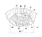
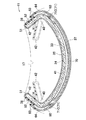
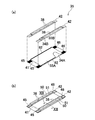
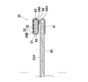
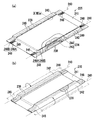
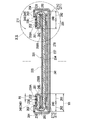
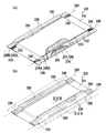
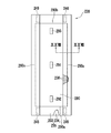
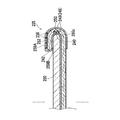
- FIG. 17 The perspective view of the liquid absorption structure of the diaper which concerns on 3rd Embodiment. Sectional drawing which follows the XIII-XIII line shown in FIG.
- A The partially broken expansion
- B The partially broken perspective view of a liquid absorption structure.
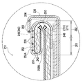
- A) The elements on larger scale enclosed with the dashed-dotted line XVIII (a) in FIG. 17 (a).
- FIG. 16 is a sectional view taken along line XIX-XIX in FIG. 15.
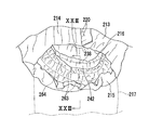
- FIG. 20 is a partially enlarged view of a portion surrounded by an alternate long and short dash line XX in FIG. 19.
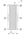
- the top view of a liquid absorption structure which shows only a joining area
- FIG. 23 is a sectional view taken along line XXIII-XXIII in FIG. 22; The top view of the liquid absorption structure of the diaper which concerns on 5th Embodiment.
- FIG. 26 is a sectional view taken along line XXVI-XXVI shown in FIG. 25.
- FIG. 28 is a sectional view taken along line XXVIII-XXVIII in FIG. 27.
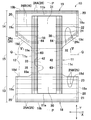
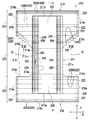
- the disposable pull-on diaper 10 shown as an example of the pull-on wearing article of the first invention has a longitudinal direction Y and a lateral direction X, a longitudinal center line P that divides the lateral direction X into two equal parts, and the longitudinal direction Y dimension.
- the horizontal center line Q is divided into two equal parts, and includes an absorption chassis 11 and an annular elastic waist panel 12.
- the term "pull-on wearing article” has a defined waist opening and a pair of leg openings, and inserts the wearer's leg into the leg opening and lifts the article over the waist to wear the wearer's body. It means what is attached to.
- the diaper 10 includes a skin facing surface and a non-skin facing surface on the opposite side, a front waist region 13, a rear waist region 14, a crotch region 15 located between the front and rear waist regions 13, 14, a waist opening and a pair.
- Leg opening 16 The waist opening is defined by an annular elastic waist panel 12, and the pair of leg openings 16 is defined by an absorption chassis 11 and an annular elastic waist panel 12.
- the elastic waist panel 12 includes a front waist panel 18 located in the front waist region 13 and a rear waist panel 19 located in the rear waist region 14.
- the front and rear waist panels 18 and 19 are opposed to the intermediate inner end edges 18a and 19a in the longitudinal direction Y while crossing the front and rear end parts 30 and 31 of the absorbent chassis 11 and extending in the lateral direction X.
- the outer edges 18b and 19b extending in the lateral direction X, the outer edges 18c and 19c extending inward from the outer edges 18b and 19b, the outer edges 18c and 19c, and the intermediate inner edges 18a and 19a It is formed in a substantially trapezoidal shape by the concave curved inner edges 18d and 19d.
- Each of the outer edges 18c of the front waist panel 18 and the outer edges 19c of the rear waist panel 19 are overlapped with each other and connected by side seams 20 extending intermittently in the longitudinal direction Y, thereby forming a waist opening and a pair.
- Leg openings 16 are defined.
- sheets that overlap each other are fused by embossing / debossing with heat or ultrasonic waves.
- the front and rear waist panels 18 and 19 include inner layer sheets 21 and 22 positioned on the skin facing surface side, outer layer sheets 23 and 24 positioned on the clothing facing surface side, and a plurality of strips extending in the lateral direction X.
- Front and rear waist elastic bodies 25 and 26 formed of a string-like or strand-like elastic material and attached so as to be shrinkable in a stretched state with, for example, a hot melt adhesive between the inner and outer layer sheets 21, 22, 23, and 24 .
- the front waist elastic body 25 is composed of an outer front waist elastic body 25A extending in the lateral direction X along the outer end edge 18b of the front waist panel 18 and a pair of inner front waist elastic bodies arranged to be opposed to each other in the lateral direction X. 25B.
- the rear waist elastic body 26 includes an outer rear waist elastic body 26A extending in the lateral direction X along the outer edge 19b of the rear waist panel 19 and a pair of intermediate rear waist elastic bodies disposed to face each other in the lateral direction X. 26 ⁇ / b> B and a pair of inner rear waist elastic bodies 26 ⁇ / b> C that extend in a concave manner along the inner edge 19 d and that are spaced apart from each other in the lateral direction X.
- Various sheets constituting the front and rear waist panels 18, 19, that is, the inner and outer layer sheets 21, 22, 23, 24, are known, for example, a spunbond fiber nonwoven fabric or an SMS (spunbond / meltblown / spunbond) fiber nonwoven fabric. It can be formed from a fiber nonwoven fabric, a laminate sheet of a plastic film and a nonwoven fabric, or the like. The laminated sheets are joined to each other by, for example, a hot melt adhesive or heat welding means applied intermittently to at least one of the inner surfaces.
- the front and rear waist elastic bodies 25 and 26 have string-like or strand-like elasticity, for example, having a fineness of about 300 to 1200 dtex and stretched and fixed about 1.8 to 3.5 times from a contracted or relaxed state. It can be formed from a material.
- the absorption chassis 11 has a vertically long and substantially rectangular shape, and is connected to the skin facing surface of the front waist panel 18 and the skin end facing surface of the rear waist panel 19. It has an end portion 31 and an intermediate portion 32 that extends in the longitudinal direction Y between the front and rear end portions 30 and 31 and forms part of the crotch region 15.
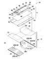
- the absorption chassis 11 includes a liquid-absorbing structure 35 having a liquid-permeable body-side liner 33 and an absorber 34 coated on the body side, and a clothing-facing surface side of the absorber 34. And a hydrophobic covering sheet 36 located therein.
- the body side liner 33 can be formed from, for example, a spunbond fiber nonwoven fabric, an SMS fiber nonwoven fabric or the like that has been subjected to a hydrophilic treatment.
- the covering sheet 36 is formed from a hydrophobic SMS fiber nonwoven fabric or a spunbond nonwoven fabric.
- a leak-proof sheet 37 formed from a plastic film having moisture permeability and liquid impermeability is disposed.
- the leak-proof sheet 37 is an option, and in the present embodiment, the joining areas 70 and 71 described later are provided for joining the liquid absorbing structure 35 and the leak-proof sheet 37. When not disposed, the liquid absorbing structure 35 and the covering sheet 36 are joined.
- the absorbent body 34 includes, for example, a liquid absorbent core 43 formed of an absorbent / discrete material such as wood fluff pulp or super absorbent polymer particles (SAP), and a mass of about 10 covering the entire liquid absorbent core 43. And a liquid-permeable core cover sheet 44 formed of tissue paper or the like of ⁇ 20 g / m 2 .
- the liquid absorption structure 35 includes a first absorption part (center part) 41, a pair of bending lines 40 that are located on both sides of the first absorption part 41 and extend in the vertical direction, It has the 2nd absorption part (both side part) 42 located in the outer side of the horizontal direction X from the bending line 40.
- the second absorption part 42 is fixed to the first absorption part 41 via a front end fixing part 45 and a rear end fixing part 46, for example, coated with a hot melt adhesive, which are located on the first absorption part 41 along the bending line 40. Is done.
- a plurality of side elastic bodies 38 are attached to the surface of the second absorbent portion 42 opposite to the surface where the front and rear end fixing portions 45 and 46 are located.
- the side elastic body 38 is extended in the wearing state of the diaper 10 by bending both side portions of the liquid absorbing structure 35 inward and fixing them through the front and rear end fixing portions 45 and 46.
- the 2nd absorption part 42 gets up toward a wearer's body.
- the front and rear end fixing portions 45 and 46 are front and rear end portions of the liquid absorption structure 35 and are located on the proximal portion 50 side of the second absorption portion 42.
- the front and rear end fixing portions 45 and 46 are positioned so as to overlap the elastic waist panel 12 in plan view.
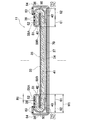
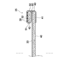
- the second absorbent portion 42 includes a contact surface 59 ⁇ / b> A that contacts the wearer's body in a worn state, a non-contact surface 59 ⁇ / b> B that is positioned on the opposite side, and a first absorption portion 41.
- the position part 50 and the distal part 51 located in the longitudinal centerline P side rather than the proximal part 50 are included. Since the second absorbent portion 42 includes the absorbent body 34 and the liquid-permeable body-side liner 33 that covers the body side, the entire outer surface (the contact surface 59A and the non-contact surface 59B) is transparent. It has liquidity.
- the side elastic body 38 is located on the contact surface 59A side of the second absorption portion 42 and is disposed between the body side liner 33 and the liquid-permeable fixing sheet 52.
- the fixing sheet 52 is optional, and a side elastic body 38 can be disposed between the body side liner 33 and the absorbent body 34, but when the diaper 10 is manufactured, it is directly attached to the semi-rigid absorbent body 34.
- the side elastic body 38 can be attached more stably by interposing the fixing sheet 52.
- the second absorbent portion 42 is divided into a first section 61 located on the distal portion 51 side and a second section 62 located on the proximal portion 50 side, which divides the width dimension into two equal parts.
- the mass per unit area of the liquid absorbing structure 35 in the first and second absorption parts 41 and 42 (excluding the bonding material for bonding the constituent members) is about 200, for example. ⁇ 600 g / m 2 , preferably 350 to 450 g / m 2 , and the total thickness of the liquid absorbing structure 35 is substantially uniform.
- the thickness of the first absorption part 41 may be larger than that of the second absorption part 42 in order to absorb and retain a larger amount of body fluid in the first absorption part 41, and conversely, the second absorption.
- the thickness of the part 42 may be larger than that of the first absorption part 41.
- the second absorbent portion 42 has a relatively high rigidity, and is difficult to break even if it is sandwiched between the wearer's crotch, and can maintain a raised state.
- the side elastic body 38 is, for example, a string-like or strand-like elastic material having a fineness of about 400 to 1200 dtex and stretched and fixed about 1.8 to 4.0 times from a contracted or relaxed state. Can be formed from The side elastic bodies 38 are evenly arranged over the entire width dimension (dimension in the lateral direction X) W1 from the proximal portion 50 to the distal portion 51 of the second absorbent portion 42, and the entire second absorbent portion 42 is disposed. Has elasticity.
- “the side elastic bodies 38 are evenly arranged” is a dimension in design and includes a slight dimensional error that occurs in an actual manufacturing process.
- the side elastic body 38 may be disposed at least in a part of each of the first and second sections 61 and 62 rather than the entire second absorbing section 42.
- you may form from elastic sheets, such as a stretchable fiber nonwoven fabric arrange
- the width dimension W1 of the second absorber 42 is, for example, about 20 to 60 mm, and the separation dimension R1 (pitch) between the side elastic bodies 38 is about 5 to 15 mm.
- the separation dimension R1 is an appropriate size, and the fineness and the expansion ratio of the side elastic body 38 are within the above-described preferable ranges, the second absorbent portion 42 exhibits the required elongation stress. sell.
- the extension stress of the side elastic body 38 may be substantially equal, or the extension stress can be changed by changing the extension magnification partly as necessary.
- both side portions of the covering sheet 36 are bent inward, and the front and rear end portions thereof are on the liquid absorbing structure 35 (on the second absorbing portion 42) via the joint portion 65. It is fixed to.
- a plurality of strings or strands extending in the longitudinal direction Y for example having a fineness of about 300 to 1000 dtex and extending about 1.6 to 3.0 times from a contracted or relaxed state
- a flap elastic body 63 which is a shaped elastic material, is disposed. By arranging the flap elastic body 63, barrier cuffs 64 are formed that rise to the wearer's body side in the wearing state of the diaper 10 by the contraction action.
- the liquid absorbing structure 35 is applied to the surface of the covering sheet 36 (or the leakage preventing sheet 37 when the leakage preventing sheet 37 is disposed) facing the liquid absorbing structure 35.
- it is fixed to the cover sheet 36 (or the leak-proof sheet 37 when the leak-proof sheet 37 is arranged) via the joining regions 70 and 71 formed of a hot melt adhesive.
- the joint regions 70 and 71 are located in the center in the lateral direction X of the liquid absorbing structure 35, and the central joint region 70 extending in the vertical direction Y from the front end edge to the rear end edge of the liquid absorbing structure 35, and the central joint region 70.
- Side junction regions 71 that are spaced apart by a given dimension on both sides in the lateral direction X.
- the side joint region 71 is located on the lower surface of the proximal portion 50 of the second absorption part 42, and is provided with both end joints 71A and 71B located on the front and rear end edges of the liquid absorbing structure 35, and both end joints 71A and 17B.
- Intermediate joint 71C located between the two.
- the intermediate joint portion 71C and both end joint portions 71A and 71B are located apart from each other in the longitudinal direction Y by a given dimension.
- the central portion of the liquid absorption structure 35 (that is, the center of the first absorption portion 41) is stably fixed to the covering sheet 36 via the central joint region 70, while the liquid absorption structure 35
- the absorbent chassis 11 Since the entire clothing facing surface is not fixed to the covering sheet 36 with, for example, a hot melt adhesive, the absorbent chassis 11 is entirely compared with a case where the entire clothing facing surface is fixed to the covering sheet 36 with a hot melt adhesive. Has flexibility.
- region 71 is located in the lower surface of the proximal part 50 of the 2nd absorption part 42, when wearing the diaper 10 as above-mentioned, the 2nd absorption part 42 starts from the proximal part 50. Can get up toward the wearer's body.
- the second absorbent portion 42 rises toward the wearer's body 17 due to the contraction force of the side elastic body 38.
- the side elastic bodies 38 are evenly arranged over the entire width of the second absorbent portion 42, and the side elastic bodies 38 of the first area 61 and the second area 62 are used.
- the shrinkage dimensions are substantially the same, not only the distal portion 51 but the entire abutment surface 59A abuts the wearer's thigh substantially in a planar shape. Therefore, compared with the case where only the distal portion 51 is in contact with the wearer's body 17, the contact area with the body is large, the fit is excellent, and the body fluid that has reached the body 17 can be reliably absorbed and retained. it can.
- the second absorbent portion 42 includes a compression-absorbing liquid-absorbing core 43 therein and has a required thickness and rigidity.
- a solid cuff formed only from a sheet member having elasticity in a conventional diaper is used. Is more stably fitted by the wearer's body 17 than the like, and in particular, there is a gap between the body 17 and the second absorption part 42 that causes leakage of bodily fluids in a state where the wearer is lying down. By being formed, it is possible to suppress excrement from side leakage from the leg opening 16.
- the absorption chassis 11 that has absorbed bodily fluids from its proper position due to its own weight. Since the second absorbent portion 42 fits to the body in a relatively wide range, it is possible to suppress the slipping down because the second absorbing portion 42 fits the body in a relatively wide range.
- the second absorption part 42 fits the wearer's body 17 in a planar shape, so that it can be said that the absorption efficiency is higher than when only a part of the second absorption part 42 fits and absorbs body fluid.
- the contact surface 59A of the second absorption part 42 has liquid permeability, the body fluid that leaks out beyond the apex (distal part 51) of the second absorption part 42 through the body 17. Can be absorbed and held at the contact surface 59A of the second absorbing portion 42.
- the entire surface including the non-contact surface 59B of the second absorbent portion 42 is liquid permeable, the excreted body fluid is first separated from the skin facing surface of the first absorbent portion 41.
- the non-contact surface 59B of the second absorption part 42 It penetrates through the non-contact surface 59B of the second absorption part 42 and is absorbed and held by them.
- the bodily fluid that has passed through the body and moved to the skin facing surface side of the liquid absorbing structure 35 beyond the top of the second absorbing portion 42 is absorbed and held from the contact surface 59A of the second absorbing portion 42.
- the non-contact surface 59B of the second absorbent portion 42 may be liquid-impervious or hardly liquid-permeable. In such a case, absorption of bodily fluid from the non-contact surface 59B is suppressed, while leakage of excrement moving in the lateral direction X in the diaper 10 can be effectively suppressed.
- the barrier cuff 64 of the covering sheet 36 rises toward the wearer's body 17 by the contraction force of the flap elastic body 63 outside the second absorbent portion 42.
- the width dimension W1 of the second absorption part 42 is larger than the width dimension of the barrier cuff 64 in the lateral direction X.
- the width of the second absorption part 42 from the side edge of the crotch area 15 is larger than the dimension in the lateral direction X from the side edge of the crotch region 15 to the distal portion of the covering sheet 36.
- the second absorption part 42 is higher than the barrier cuff 64 and the barrier cuff 64 does not cover the second absorption part 42.
- the barrier cuff 64 is preferably liquid-impervious or water-repellent, moves through the wearer's body toward the contact surface 59A of the second absorbent portion 42, and is not absorbed by the contact surface 59A. It has a function to suppress leakage. Further, the second absorbent portion 42 raised by the contracting action of the side elastic body 38 is easily sandwiched between the crotch and easily folds outward.
- the barrier cuff 64 is positioned on the outer side, so that the second absorbent portion 42 is located on the outer side.
- the barrier cuff 64 forms a double leak-proof wall together with the second absorption portion 42 and plays a role of assisting the rising of the second absorption portion 42. Further, as described above, in the diaper 10 in which the front and rear waist regions 13 and 14 are formed from the separate front and rear waist panels 18 and 19, the absorption chassis 11 is likely to slide down from an appropriate position by its own weight after absorbing body fluid. However, since not only the second absorption part 42 but also the barrier cuff 64 is fitted to the body, such sliding down can be prevented.
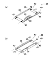
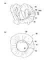
- FIG. 9A is a diagram showing a state in which the second absorbent portion 42 is cut out from the diaper 10 of the present embodiment and the side elastic body 38 is contracted
- FIG. 9B is a comparative example.
- the 2 absorption part 42 it is a figure which shows the state which attached the side part elastic body 38 only to the distal part 51, cut out it from the diaper, and the side part elastic body 38 was contracted.
- the second absorbent portion 42 cut out from the diaper 10 is arranged with the side elastic bodies 38 spaced apart equally from the proximal portion 50 to the distal portion 51.
- the first area 61 and the second area 62 are not deformed and have a three-dimensional shape having a hollow circular cross section with the abutting surface 59A surrounding the central space (having a required height) as an inner peripheral wall as a whole.
- the 2nd absorption part 42 becomes the aspect which stood up in the state cut out from the diaper 10 by the shrinkage
- the vertical dimension Y in the contracted state of the first section 61 and the vertical dimension in the contracted state of the second section 62 are substantially equal.
- the second area 62 is connected to the first absorption part 41 and the shrinkage is suppressed.
- the amount of contraction is smaller than that of the first area 61.
- the dimension of the first area 61 in the contracted state is larger than the dimension of the second area 62 in the contracted state of the longitudinal direction Y.
- the former is about 315 mm and the latter is about 365 mm.
- the contraction amount of the distal portion 51 is close. Since the contraction dimensions of the proximal portion 50 and the distal portion 51 are different from each other, the second absorbent portion 42 does not have a three-dimensional shape that forms a peripheral wall, but a flat ring shape. . As is apparent from the form of the second absorbent portion 42 in the state cut out from the diaper 10 in FIGS. 9A and 9B, the second absorbent portion 42 is deformed as shown in FIG.
- the side elastic body 38 is disposed in at least a part of the first and second areas 61 and 62, and the side elastic body 38 is It is necessary to adjust various conditions such as the number (pitch), fineness, and expansion ratio.
- concave grooves 80 extending in the vertical direction Y are formed in portions overlapping the folding lines 40 on both sides of the liquid absorbing structure 35. ing.
- the liquid absorbing core 43 does not exist or its mass is smaller than other portions and is thin.
- the concave groove 80 partially, particularly in the crotch region 15, a region where the second absorbent portion 42 is easily contracted in the longitudinal direction Y is formed, and the rising property and the surface fitting property of the second absorbent portion 42 are formed. Will improve.
- the concave groove 80 is formed so as to overlap with the bending line 40, the second absorbing portion 42 can be easily bent inward in the manufacturing process.
- the first absorption part 41 and the second absorption part 42 of the liquid absorption structure 35 are formed separately.
- the first absorption part 41 is composed of a first body side liner 33A and a first absorbent body 34A covered with the first body side liner 33A
- the second absorption part 42 includes a second body side liner 33B, It has the 2nd absorber 34B coat
- the second absorption portion 42 is joined to the first absorption portion 41 via a fixing portion 82 and front and rear end fixing portions 45 and 46 that continuously extend in the longitudinal direction Y along both side edges.
- the second absorption part 42 has a proximal part 50 fixed via a fixing part 82 and a distal part 51 located inside the proximal part 50 in the lateral direction X. Also in this embodiment, the contact surface 59 ⁇ / b> A of the second absorption part 42 has liquid permeability, and rises toward the wearer's body 17 by the contraction force of the side elastic body 38.
- the front and rear waist regions 13 and 14 are not configured from separate sheet members, and the front and rear waist regions 13 and 14 and the crotch region 15 may be integrally formed.
- the inner and outer layer sheets 21, 22, 23, and 24 may be formed from a single substantially hourglass-shaped sheet member that forms the outer shape of the diaper 10.
- the disposable pull-on diaper 210 shown as an example of the pull-on wearing article of the second invention includes a longitudinal direction Y and a transverse direction X, and a longitudinal center line P that bisects the dimension in the transverse direction X. And a horizontal center line Q that bisects the dimension in the longitudinal direction Y, and includes an absorption chassis 211 and an annular elastic waist panel 212.
- the diaper 210 includes a skin facing surface and a clothing facing surface on the opposite side, a front waist region 213, a rear waist region 214, a crotch region 215 located between the front and rear waist regions 213 and 214, a waist opening, and a pair of Leg opening 216.
- the waist opening is defined by an annular elastic waist panel 212
- the pair of leg openings 216 is defined by an absorption chassis 211 and an annular elastic waist panel 212.
- the elastic waist panel 212 includes a front waist panel 218 located in the front waist region 213 and a rear waist panel 219 located in the rear waist region 214.
- the front and rear waist panels 218 and 219 are spaced apart from the intermediate inner end edges 218a and 219a that intersect the front and rear end portions 230 and 231 of the absorption chassis 211 and extend in the horizontal direction X, and the intermediate inner end edges 218a and 219a in the vertical direction Y.
- outer end edges 218b and 219b extending in the lateral direction X, the outer edges 218c and 219c extending downward from the outer ends 218b and 219b, the outer edges 218c and 219c, and the intermediate inner edges 218a and 219a are connected.
- a substantially trapezoidal shape is formed by the concavely curved inner edges 218d and 219d.
- Each of the outer edge 218c of the front waist panel 218 and the outer edge 219c of the rear waist panel 219 are overlapped with each other and connected by a side seam 220 extending intermittently in the longitudinal direction Y, thereby forming a waist opening and a pair of legs.
- An opening 216 is defined.
- the overlapping sheets are fused by embossing / debossing with heat or ultrasonic waves.
- the front and rear waist panels 218 and 219 include inner layer sheets 221 and 222 located on the skin facing surface side, outer layer sheets 223 and 224 located on the clothing facing surface side, and a plurality of strips extending in the lateral direction X. It has front and rear waist elastic bodies 225 and 226 that are formed of a string-like or strand-like elastic material, and are attached between the inner and outer layer sheets 221 to 224 so as to be shrinkable in a stretched state via, for example, a hot melt adhesive.
- the front waist elastic body 225 is composed of an outer front waist elastic body 225A extending in the lateral direction X along the outer edge 218b of the front waist panel 218, and a pair of inner front waist elastic bodies disposed to be opposed to each other in the lateral direction X.
- the rear waist elastic body 226 is composed of a pair of intermediate rear waist elastic bodies 226 ⁇ / b> A and an outer rear waist elastic body 226 ⁇ / b> A that extends in the lateral direction X along the outer edge 219 b of the rear waist panel 219.
- 226B and a pair of inner rear waist elastic bodies 226C that extend in a concave manner along the inner edge 219d and that are spaced apart from each other in the lateral direction X.
- Various sheets constituting the front and rear waist panels 218, 219 that is, the inner and outer layer sheets 221, 222, 223, and 224 are known fiber nonwoven fabrics such as spunbond fiber nonwoven fabric or SMS (spunbond / meltblown / spunbond) fiber nonwoven fabric. It can be formed from a laminate sheet of a moisture-permeable plastic film and a nonwoven fabric. The laminated sheets are joined to each other by, for example, a hot melt adhesive or the above-mentioned heat welding means applied intermittently to at least one of the inner surfaces.
- a hot melt adhesive or the above-mentioned heat welding means applied intermittently to at least one of the inner surfaces.
- the front and rear waist elastic bodies 225 and 226 have, for example, a string shape or a strand shape having a fineness of about 300 to 1200 dtex and stretched and fixed about 1.8 to 3.5 times from a contracted or relaxed state. It can be formed from an elastic material.
- the absorption chassis 211 is a vertically long, substantially rectangular shape, and is connected to the skin facing surface of the front waist panel 218 and the skin facing surface of the rear waist panel 219.
- An end portion 231 and an intermediate portion 232 extending in the longitudinal direction Y between the front and rear end portions 230 and 231 and forming a part of the crotch region 215 are included.
- the absorption chassis 211 includes, for example, a liquid-absorbing structure 235 having a liquid-permeable body-side liner 233 and an absorber 234 coated on the body side, and a clothing-facing surface of the absorber 234. And a hydrophobic covering sheet 236 located on the side.
- the body side liner 233 can be formed from, for example, a spunbond fiber nonwoven fabric, an SMS fiber nonwoven fabric or the like that has been subjected to a hydrophilic treatment.
- the covering sheet 236 is formed of a hydrophobic SMS fiber nonwoven fabric or a spunbond nonwoven fabric.
- a leak-proof sheet 237 formed from a plastic film having moisture permeability and liquid impermeability is disposed between the covering sheet 236 and the liquid-absorbing structure 235.
- the leak-proof sheet 237 is optional, and in the present embodiment, the joining portions 270 and 271 described later are for joining the liquid absorbing structure 235 and the leak-proof sheet 237. When not disposed, the liquid absorbing structure 235 and the covering sheet 236 are joined.
- the absorbent body 234 includes, for example, a liquid absorbent core 243 formed of an absorbent / discrete material such as wood fluff pulp and super absorbent polymer particles (SAP), and a mass of about 10 to 10 covering the entire liquid absorbent core. And a liquid-permeable core cover sheet 244 formed of 20 g / m 2 tissue paper or the like.
- a liquid absorbent core 243 formed of an absorbent / discrete material such as wood fluff pulp and super absorbent polymer particles (SAP), and a mass of about 10 to 10 covering the entire liquid absorbent core.
- a liquid-permeable core cover sheet 244 formed of 20 g / m 2 tissue paper or the like.
- the liquid absorption structure 235 is positioned on both sides of the first absorption portion (center portion) 241 and the first absorption portion 241 and extends in the vertical direction Y. It has a pair of bending lines 240 and a second absorption part (both side parts) 242 located outside the bending line 240 in the lateral direction X.
- the both side portions 242 are fixed through a front end fixing portion 245 and a rear end fixing portion 246 that are bent inward along the bending line 240 and are applied to the first absorbent portion 241, for example, coated with a hot melt adhesive. .
- a plurality of side elastic bodies 238 are attached to the surface of the second absorbent portion 242 opposite to the surface where the front and rear end fixing portions 245 and 246 are located.
- the side elastic body 238 is extended in the wearing state of the diaper 210 by bending both sides of the liquid absorbing structure 235 inward and fixing them through the front and rear end fixing parts 245 and 246.
- the second absorption part 242 rises toward the wearer's body.
- the front and rear end fixing portions 245 and 246 are located at the front and rear end portions of the liquid absorption structure 235 and on the proximal portion 250 side of the second absorption portion 242 described later.
- the front and rear end fixing portions 245 and 246 are positioned so as to overlap the elastic waist panel 212 in the plan view of the diaper 210.
- the “folding line 240” is a portion where a part of the liquid absorption structure 235 is bent, and in addition to the line shape being visible in the bent state, It includes the case where the shape is not bent so that it can be visually recognized when unfolded.
- the liquid absorbing structure 235 has a pair of concave bent guide portions 248 extending in the vertical direction Y along the bent line 240.
- the bending guide portion 248 is a concave groove formed by embossing / debossing extending in the vertical direction Y, and has a plurality of concave grooves 248A and 248B spaced apart from each other in the horizontal direction X.
- the concave grooves 248A and 248B have a plurality of compression concave portions 249 that are intermittently arranged in the longitudinal direction Y.
- the plurality of compression recesses 249 are arranged, so that the bending guide portion 248 is thinner and more rigid than the other portions. Since the bending guide portion 248 having a relatively high rigidity is formed along the bending line 240, when the both side portions 242 are bent toward the central portion 241, the bending guide portion 248 can be easily bent.
- a part of the absorber 234 may be removed or only the portion of the absorber 234 having a substantially uniform thickness may be compressed and deformed.
- the part 248 is formed by the latter method (embossing / debossing). Therefore, the bending guide portion 248 has a thickness dimension smaller than that of other portions, and is relatively high rigidity and high density by being compressed. Therefore, the bending guide part 248 can easily be a starting point of bending, and can quickly move the body fluid that has entered in the longitudinal direction Y.
- the absorbent core 243 of the absorbent body 234 is formed from a mixture of SAP and wood fluff pulp, and the content of wood fluff pulp in the bending guide portion 248 is higher than that of other portions. Is preferred. Specifically, in this embodiment, the content of the wood fluff pulp is about 55 to 65% by mass (the SAP content is about 45 to 35% by mass) in the portion excluding the bending guide portion 248. In the bending guide portion 248, the wood fluff pulp content is preferably set to about 75 to 90% by mass (SAP content is about 25 to 10% by mass).
- FIG. 18A is a partially enlarged view of the region surrounded by the alternate long and short dash line XVIII (a) in FIG.
- the plurality of compression recesses 249 forming the respective concave grooves 248A and 248B are defined by both end edges 249a and 249b facing in the length direction and both side edges 249c facing in the width direction. It has a substantially rectangular shape.
- Each compression recess 249 of the recessed grooves 248A and the compression recesses 249 of the recess grooves 248B adjacent to each other in the lateral direction X are arranged so as to be displaced from each other in the lateral direction X and the longitudinal direction Y, and do not intersect with each other in the lateral direction X
- Each compression recess 249 includes a low compression portion 253 and a plurality of high compression portions 254 surrounded by the low compression portion 253.
- the absorber 234 is compressed deeper (stronger) than the low compression part 253, and the thickness dimension is smaller than that of the low compression part 253, and the rigidity is higher. Density.
- the thickness dimension (the deepest thickness dimension at which the high compression part 254 is located) D2 of the compression recess 249 of the bending guide part 248 ensures that the liquid absorbing structure 235 is bent.
- the size is preferably about 45 to 85% of the thickness D1 of the liquid absorption structure 235.
- the ratio is less than about 45%, the liquid absorbing structure 235 cannot be reliably bent at the bending line 240, and the second absorption is particularly caused by a change in the posture of the wearer in the wearing state.
- the bending guide portion 248 is a concave groove that is concave on the skin-facing surface side of the absorbent body 234, but the absorbent body 234 is bent via the bending guide portion 248 to make the second absorbent portion 242 the first. As long as it can be positioned on the absorbent portion 241, it may be a concave groove that is concave on the surface of the absorbent body 234 facing the cover sheet 236. However, in the former case, it is easier to bend the first absorbent portion 241 and the second absorbent portion 242 along the folding line 240 so that the skin facing surfaces face each other, compared to the latter case, And it can be said that it is easy to induce the bodily fluid excreted to the skin facing surface side.
- the bending guide portion 248 only needs to be positioned so as to overlap with at least a part of the bending line 240. Further, from the viewpoint of preventing side leakage, the liquid absorbing structure It suffices if they are positioned so as to overlap each other at the folding line 240 on at least one side of both sides of the body 235.
- the second absorption part 242 is connected to the first absorption part 241, the contact surface 259 ⁇ / b> A that contacts the wearer's body in the wearing state, the non-contact surface 259 ⁇ / b> B located on the opposite side. It has the proximal part 250 and the distal part 251 located inward from the proximal part 250 (to the longitudinal center line P side). Since the second absorbent portion 242 includes the absorbent body 234 and a liquid-permeable body-side liner 233 that covers the body side, the entire outer surface (the contact surface 259A and the non-contact surface 259B) is transparent. It has liquidity.
- the side elastic body 238 is located on the contact surface 259A side of the second absorbent portion 242, and is disposed between the body side liner 233 and the liquid-permeable fixing sheet 252.
- the fixing sheet 252 is optional, and a side elastic body 238 can be disposed between the body side liner 233 and the absorbent body 234, but when the diaper 210 is manufactured, it is directly attached to the semi-rigid absorbent body 234. Compared to the case where the side elastic body 238 is attached to the side elastic body 238, the side elastic body 238 can be attached more stably by interposing the fixed sheet 252.
- the second absorption part 242 is divided into a first area 261 located on the distal part 251 side and a second area 262 located on the proximal part 250 side, which bisect the width dimension.
- the mass per unit area of the liquid absorption structure 235 in the first and second absorption parts 241 and 242 is, for example, about 200 to
- the thickness is 600 g / m 2 , preferably 350 to 450 g / m 2 , and the thickness of the entire liquid absorbing structure 235 is substantially uniform except for the bending guide portion 248.
- the thickness of the first absorption part 241 may be larger than that of the second absorption part 242 in order to absorb and retain a larger amount of body fluid in the first absorption part 241, and conversely, the second absorption.
- the thickness of the part 242 may be larger than that of the first absorption part 241.
- the second absorbent portion 242 has a relatively high rigidity, and is difficult to break even if sandwiched between the groin portion of the wearer, and can maintain a raised state.
- the side elastic body 238 is formed of a string-like or strand-like elastic material having a fineness of about 400 to 1200 dtex and stretched and fixed about 1.8 to 4.0 times from a contracted or relaxed state. can do.
- the side elastic bodies 238 are evenly arranged over the entire width dimension (dimension in the lateral direction X) from the proximal portion 250 to the distal portion 251 of the second absorbent portion 242, and the entire second absorbent portion 242 expands and contracts. Have sex.
- “the side elastic bodies 238 are evenly arranged” is a dimension in design and includes a slight dimensional error generated in an actual manufacturing process.
- the side elastic body 238 is disposed not in the entire second absorbent portion 242 but in at least a part of each of the first area 261 and the second area 262. Just do it. Further, the side elastic body 238 is not a string-like or strand-like elastic material, but is formed of an elastic sheet such as a stretchable fiber nonwoven fabric disposed in both areas across the first area 261 and the second area 262. May be.
- the width dimension W1 of the second absorption part 242 is about 20 to 60 mm, and the separation dimension R1 (pitch) between the side elastic bodies 238 is about 5 to 15 mm. It is.
- the entire second absorbent portion 242 needs to have a required elongation stress. If the separation dimension R1 is an appropriate size, and the fineness and expansion ratio of the side elastic body 238 are within the above-described preferable ranges, the second absorbent portion 242 exhibits the required elongation stress. Yes.
- the extension stress of the side elastic body 238 may be substantially equal, or the extension stress can be changed by partially changing the extension magnification as necessary.
- both side portions of the covering sheet 236 are bent inward, and front and rear end portions thereof are fixed on the liquid absorbing structure 235 (on the second absorbing portion 242) via the joint portion 265.
- a plurality of strings extending in the longitudinal direction Y for example, having a fineness of about 300 to 1000 dtex and stretched and fixed about 1.6 to 3.0 times from a contracted or relaxed state
- a flap elastic body 263 made of an elastic material in the form of a strand or a strand is disposed.
- the liquid absorbing structure 235 is applied to the surface of the covering sheet 236 (or the leakage preventing sheet 237 when the leakage preventing sheet 237 is disposed) facing the liquid absorbing structure 235.
- it is fixed to the covering sheet 236 (or the leakage preventing sheet 237 when the leakage preventing sheet 237 is disposed) via the joint portions 270 and 271 formed from a hot melt adhesive.
- the joints 270 and 271 are located at the center in the lateral direction X of the liquid absorbing structure 235, and a central joint 270 that extends in the vertical direction Y from the front edge to the rear edge of the liquid absorbent structure 235, and the central joint 270.
- Side joints 271 that are spaced apart by a given dimension on both sides in the lateral direction X.
- the side joint part 271 is located on the lower surface of the proximal part 250 of the second absorption part 242, and is joined to both end joint parts 271A and 271B and the both end joint parts 271A and 217B located on the front and rear edge sides of the liquid absorbing structure 235.
- Intermediate junction 271C located between the two.
- the intermediate joint portion 271C and the both end joint portions 271A and 271B are spaced apart from each other in the longitudinal direction Y by a given dimension.
- the center of the liquid absorption structure 235 (that is, the center of the first absorption part 241) is stably fixed to the covering sheet 236 via the central joint 270, while the liquid absorption structure 235 is opposed to the liquid absorption structure 235. Since the entire surface is not fixed to the covering sheet 236 with, for example, a hot melt adhesive, the absorbent chassis 211 is generally flexible as compared with the case where the entire surface is fixed to the covering sheet 236 with a hot melt adhesive. Have Moreover, since the side junction part 271 is located in the lower surface of the proximal part 250 of the 2nd absorption part 242, when wearing the diaper 210 as above-mentioned, the 2nd absorption part 242 starts from the proximal part 250. Can get up toward the wearer's body.
- the second absorbent portion 242 rises toward the wearer's body 217 due to the contraction force of the side elastic body 238.
- the side elastic bodies 238 are evenly arranged over the entire width of the second absorbent portion 242, and the side elastic bodies 238 of the first area 261 and the second area 262 are used.
- the shrinkage dimensions are substantially the same, not only the distal portion 251 but also the entire abutting surface 259A of the second absorbent portion 242 abuts the wearer's thigh substantially in a planar shape. Therefore, compared with the case where only the distal portion 251 contacts the wearer's body 217, the contact area with the body 217 is large, the fit is excellent, and the body fluid that has reached the body 217 is reliably absorbed and retained. Can do.
- the second absorption portion 242 includes a compression elastic absorber 234 inside and has a required thickness and rigidity, for example, compared to a three-dimensional cuff or the like formed only from a sheet member having elasticity in a conventional diaper, for example.
- the wearer's body 217 is stably fitted.
- the absorption chassis 211 that has absorbed bodily fluids is displaced from its proper position by its own weight. Since the second absorption part 242 fits the body 217 in a relatively wide range, it is possible to suppress the sliding down because the second absorption part 242 fits the body 217 in a relatively wide range.
- the absorption efficiency is higher than when only a part of the second absorption part 242 fits and absorbs body fluid. Can be said to be expensive.
- the contact surface 259A of the second absorption part 242 is liquid permeable, it leaks to the outside through the top of the second absorption part 242 (distal part 251) through the body 217. The discharged body fluid can be absorbed and held on the skin-facing surface (contact surface 259A) of the second absorbent portion 242.
- the entire body including the non-contact surface 259B of the second absorption part 242 has liquid permeability, so that the excreted body fluid is in contact with the skin facing surface of the first absorption part 241 and the first surface. 2 Absorbs and is held by the non-contact surface 259B of the absorbent portion 242, and as described above, moves across the top of the second absorbent portion 242 to the skin facing surface side through the body. The body fluid thus absorbed is absorbed and held from the contact surface 259A.
- the non-contact surface 259B of the second absorbent portion 242 may be liquid-impervious or hardly liquid-permeable as long as the required body fluid is absorbed and held by the first absorbent portion 241. In such a case, absorption of bodily fluid from the non-contact surface 259B side is suppressed, while leakage of excrement moving in the lateral direction X in the diaper 210 can be effectively suppressed.
- the bending line 240 according to the present invention is the second absorbing portion 242.
- the bent state is not easily released due to a change in posture during wearing, etc. It is necessary.
- the bending guide portion 248 formed from the plurality of compression concave portions 249 extending along the bending line 240 on the skin facing surface side of the liquid absorbing structure 235 is disposed.
- the bent state is easily maintained, and the bent state during wearing is not inadvertently released.
- the compression recess 249 preferably has the required thickness dimension D2 and / or the suction thickness having the required thickness dimension so that the bent state can be maintained more stably.
- the bending guide portion 248 is preferably formed by a plurality of concave grooves 248A and 248B instead of a single one. That is, in the wearing state, the second absorbent portion 242 can be flexibly swung from the state in which the second absorbent portion 242 is in contact with the first absorbent portion 241 to about 180 degrees.
- the outer shape of the bent portion of the liquid absorbing structure 235 having the required thickness dimension D1 is not a sharp shape but a curved shape. It is preferable to bend like this.
- the bending guide portion 248 needs to have the required width dimension.
- the guide portion 248 is formed of a single concave groove having a relatively large width, the rigidity of the liquid absorbing structure 235 is excessively high in the portion compared to other portions, and the wearing feeling is impaired. There is a fear.
- the bending guide portion 248 is formed of a plurality of concave grooves 248A and 248B extending in the longitudinal direction Y and spaced apart from each other in the lateral direction X. The entire bending guide portion 248 has a required width.
- the concave grooves 248A and 248B may be two or more, and may be curved or different from each other in addition to a straight shape.
- the concave grooves 248 ⁇ / b> A and 248 ⁇ / b> B have a discontinuous shape composed of a plurality of compression concave portions 249 arranged in the vertical direction Y. Therefore, compared with the case where the concave grooves 248A and 248B are formed from a series of grooves continuously extending in the longitudinal direction Y, the rigidity can be further reduced, and the second elastic member 238 can contract by the contraction force of the side elastic body 238. By contracting together with the absorbing portion 242, the second absorbing portion 242 can be surely raised.
- each compression recesses 249 constituting the recess grooves 248A and 248B have substantially the same shape, and the compression recess 249 of the recess groove 248A and the compression recess 249 of the recess groove 248B are slightly different from each other in the lateral direction X. Arranged in a misaligned state. Therefore, compared to the case where the compression recesses adjacent to each other in the lateral direction X are arranged so as to coincide with each other in the lateral direction X, rigidity can be imparted evenly to the entire bent portion of the liquid absorbing structure 235. . Furthermore, since each compression recessed part 249 contains the low compression part 253 and the high compression part 254, this part does not become high rigidity locally, but can contribute to the balance of the rigidity of the whole bending part.
- the barrier cuff 264 of the covering sheet 236 rises toward the wearer's body 217 by the contraction force of the flap elastic body 263 outside the second absorbent portion 242. Since the width dimension of the barrier cuff 264 is smaller than the width dimension W1 of the second absorption part 242, the second absorption part 242 becomes higher than the barrier cuff 264 in the state where they rise, and the barrier cuff 264 The entire absorption part 242 is not covered.
- the width dimension in the lateral direction X from the side edge of the crotch region 215 to the side edge of the distal portion 251 of the second absorbent portion 242 is from the side edge of the crotch region 215 to the covering sheet 236. It is larger than the dimension in the lateral direction X to the distal portion.
- the barrier cuff 264 is preferably liquid-impervious or water-repellent, moves along the wearer's body 217 toward the contact surface 259A of the second absorbent portion 242, and is absorbed by the contact surface 259A. It has a function to suppress the leakage of body fluids that did not exist.
- the second absorption part 242 raised by the contracting action of the side elastic body 238 is easily sandwiched between the groin parts and easily bends outward.
- the barrier cuff 264 is located on the outer side, so that the second absorption part 242 is located. Is prevented from folding outward. That is, the barrier cuff 264 forms a double leak-proof wall together with the second absorption part 242 and plays a role of assisting the rising of the second absorption part.
- the absorption chassis 211 is likely to slide down from an appropriate position by its own weight after absorbing body fluid. Since not only the two absorption parts 242 but also the barrier cuff 264 is fitted to the body 217, the sliding can be suppressed.
- the basic configuration of the diaper 210 according to the fifth to seventh embodiments is the same as that of the fourth embodiment, and only different points will be described below.
- the bending guide portion 275 has a central concave groove 275A extending straight in the vertical direction Y, and both side concave grooves 275B and 275C located on both sides in the horizontal direction X. . Both side concave grooves 275B and 275C each have a shape in which both ends thereof are inclined toward the central concave groove 275A.
- the bending guide portion 275 may be formed of a plurality of concave grooves of three or more, and the concave grooves are mutually connected. It may have a different shape.
- a pair of slits 280 is provided at the center of the liquid absorbing structure 235 in the longitudinal direction Y so as to overlap the folding line 240 and the bending guide portion 248. Is provided. As described above, the slit 280 is partially disposed so as to overlap with the folding line 240 and the folding guide portion 248 in a plan view, so that the folding operation becomes smoother and folds are easily attached.
- the absorber 234 is compressed to have a relatively high rigidity, but by providing the slit 280 so as to overlap with the planar view, the rigidity in the region where the bending guide portion 248 is present. Can be adjusted as appropriate.
- a separate absorption pad (auxiliary pad) 290 having body fluid absorbability is disposed in the liquid absorption structure 235.
- the absorbent pad 290 has a substantially rectangular shape defined by front and rear end edges 290a and 290b extending in the lateral direction X and both side edges 290c extending in the longitudinal direction Y between the front and rear end edges 290a and 290b, and is a liquid-permeable fiber.
- a core cover sheet formed from a nonwoven fabric or tissue paper and a liquid-absorbent core encapsulated in the sheet are included.
- the absorbent pad 290 is disposed with both side edges interposed between the first absorbent portion 241 and the second absorbent portion 242 of the liquid absorbing structure 235. Since the liquid absorption structure 235 is a non-fixed region between the front and rear end fixing parts 245 and 246 of the first absorption part 241 and the second absorption part 242 on both sides thereof, the wearer holds the absorption pad 290. In the case of arrangement, for example, the second absorbent portion 242 in the non-fixed region is lifted upward with one hand, and both side edges of the absorbent pad 290 are placed between the first absorbent portion 241 and the second absorbent portion 242.
- the absorbent pad 290 having a predetermined width dimension can be properly arranged in the central portion of the absorbent chassis 211.
- the position is moved appropriately in the longitudinal direction Y as a guide while contacting the inner surface of the proximal portion 250 of the second absorbent portion 242. Can be adjusted.
- the separate absorption pad 290 can be arrange
- the both side edge parts of the absorption pad 290 are disposed so as to be sandwiched between the first absorption part 241 and the second absorption part 242, the displacement of the absorption pad 290 is suppressed.
- the absorbent pad 290 is fixed to the skin-facing surface of the liquid absorbing structure 235 (body side liner 233) via detachable fastening means 291 to 293 arranged on the surface facing the liquid absorbing structure 235. Is done.
- the fixing means 291 to 293 include a hook group and a pressure-sensitive adhesive that are fixed to a receiving portion (not shown) including a loop group of mechanical fasteners arranged on the skin-facing surface of the liquid absorbing structure 235. Etc. are formed. In this way, the absorbent pad 290 is fixed to the liquid absorbing structure 235 via the fastening means 291 to 293, so that both side edges are sandwiched between the first absorbent part 241 and the second absorbent part 242.
- the liquid absorbing structure 235 is more stably fixed.
- the fastening means 291 to 293 may be formed of a single member or a plurality of two or more members extending continuously in the longitudinal direction Y.
- the constituent materials constituting the diaper 210 of the second invention various known materials that are usually used in this type of field can be used without limitation, unless otherwise specified.
- the front and rear waist regions 213 and 214 are not formed of separate sheet members, and the front and rear waist regions 213 and 214 and the crotch region 215 may be integrally formed.
- the inner and outer layer sheets 221, 222, 223, and 224 may be formed from a single substantially hourglass-shaped sheet member that forms the outer shape of the diaper 210.
- Liquid absorbing property disposed in the crotch area, at least in the crotch area, and the crotch area located between the front and rear waist areas, the front waist area, the rear waist area, and the front and rear waist areas
- a wearing article including a liquid absorption structure including a core the liquid absorption structure is formed on at least a first absorbent portion located in the crotch region and the skin-facing surface on both sides of the first absorbent portion.
- a pair of second absorbent parts positioned and extending in the longitudinal direction, wherein the second absorbent part is a contact surface that comes into contact with a wearer's body, and a proximal part that is continuous with the first absorbent part.
- the second absorption part is divided into a first area located on the distal part side and a second area located on the proximal part side,
- the abutment surface of the second absorption part has liquid permeability, and a side elastic body extending in the longitudinal direction is disposed in the first area and the second area.
- the disposable wearing article according to the first invention disclosed in the above paragraph can include at least the following embodiments.
- the embodiments can be adopted separately or in combination with each other.
- (1) The first absorption part and the second absorption part are integrally formed, and the first absorption part is constituted by a central part of the liquid absorption structure, and the second absorption part is formed in the central part. Formed on both sides of the liquid-absorbing structure that is bent toward the skin-facing surface, and both end portions of the second absorbent portion that are separated in the longitudinal direction are interposed between a front end fixing portion and a rear end fixing portion. And fixed to the first absorption part.
- the first area and the second area divide the width dimension of the second absorbent portion into two equal parts, and in the worn state, the vertical dimension in the contracted state of the first area. Is smaller than the longitudinal dimension in the contracted state of the second zone, while the longitudinal dimension in the contracted state of the first zone when the second absorber is separated from the first absorber. The dimension and the dimension in the longitudinal direction in the contracted state of the second area are substantially equal.
- the liquid-absorbing structure further includes a liquid-permeable body side liner that covers at least the skin-facing surface of the first absorbent portion and the contact surface of the second absorbent portion, and the side portion. The elastic body is disposed between the body side liner and the liquid absorbent core.
- the liquid-absorbing structure includes a covering sheet that covers a bottom surface of the liquid-absorbing core, and a bonding area for fixing the liquid-absorbing core to the covering sheet.
- a central joint area for fixing the central part extending in the longitudinal direction of the liquid absorption structure; and a side joint area for fixing both side edges of the liquid absorption structure;
- the intermediate joint located in the lateral direction and spaced apart by a given dimension in the lateral direction, and the front and rear positions spaced apart by a given dimension in the longitudinal direction from the intermediate joint. And an end joint.
- It further has a liquid-impervious leak-proof sheet positioned between the covering sheet and the liquid-absorbing structure.
- cuff elastic members Disposed on both side portions of the covering sheet are cuff elastic members extending in the longitudinal direction to have a contracting distal portion.
- the second portion extends from a side edge of the crotch region.
- the lateral dimension from the side edge of the crotch region to the distal part of the covering sheet is larger than the lateral dimension from the side edge of the crotch region to the distal edge of the absorbent portion.
- the liquid-absorbing structure has a concave groove that extends in a vertical direction so as to overlap a bent portion, and the liquid-absorbing structure is compared with the other parts of the liquid-absorbing structure in the concave groove.
- the mass per unit area of the core is small or the liquid-absorbent core is absent.
- the second absorption portion has a three-dimensional shape with a hollow circular cross section with the contact surface as an inner peripheral wall in a state where the second elastic portion is separated from the first absorption portion and the side elastic body contracts.
- the disclosure relating to the second invention described above can be organized into at least the following matters.
- the liquid absorbent structure includes a liquid absorbent core, a first absorbent portion located at least in the crotch region, and a second absorbent located outside the lateral direction of the first absorbent portion.
- the second absorbent part is bent toward the skin facing surface side of the first absorbent part, and both end parts spaced apart in the longitudinal direction are fixed to the first absorbent part,
- the second absorbent portion is provided with a side elastic body extending in the longitudinal direction, and the liquid-absorbent core is located in the bent portion, and at least a part of the second absorbent portion is disposed in the longitudinal direction. Formed by embossing / debossing, extending in the direction Folding guide portion of Jo is located.
- the disposable wearing article according to the second invention disclosed in the above paragraph can include at least the following embodiments.
- the embodiments can be adopted separately or in combination with each other.
- the bending guide portion is formed of a plurality of concave grooves arranged in a spaced apart manner in the lateral direction.
- the bending guide portion is formed of a plurality of compression recesses that are discontinuous in the longitudinal direction and are spaced apart from each other in the longitudinal direction.
- the compression recess has a high compression portion and a low compression portion surrounding the high compression portion, and the compression recesses of the concave grooves adjacent to each other in the lateral direction have portions that do not intersect with each other in the lateral direction.
- the bending guide portion is recessed from the skin facing surface side of the liquid absorbing structure toward the clothing facing surface side.
- the liquid absorbent core is composed of a mixture of superabsorbent polymer particles and wood fluff pulp, and in the region where the bending guide portion is located, the wood fluff pulp of the liquid absorbent core The content is high compared to other parts.
- the second absorption portion is located on the skin facing surface side of the liquid absorption structure and has a contact surface that contacts the body in a worn state, and the contact surface is liquid permeable. Have. (7) In the second absorption portion, the side elastic body is located on the contact surface side.
- the liquid absorption structure has a slit extending in the longitudinal direction, and the slit overlaps a part of the bending guide portion. (9) It further has an absorption pad that can be attached to and detached from the liquid absorption structure, and both side edges extending in the longitudinal direction of the absorption pad are not fixed between the both ends of the second absorption part. It is located between the area and the first absorption part.
- Diapers (Pull-on wearing items) 12 Waist panel 13 Front waist area 14 Rear waist area 15 Crotch area 18 Front waist panel 19 Rear waist panel 33 Body side liner 34 Absorber 35 Liquid absorbing structure 36 Cover sheet 37 Leakproof sheet 38 Side elastic body 40 Folding line 41 1st absorption part 42 2nd absorption part 43 Liquid absorbing core 45 Front end fixing part 46 Rear end fixing part 50 Proximal part 51 of 2nd absorption part Distal part 61 of 2nd absorption part 1st area 62 2nd area 63 Flap elastic body 70 Central joint area (joint part) 71 Side joint area (joint) 71A front end joint 71B rear end joint 71C intermediate joint 80 concave groove 210 diaper (pull-on wearing article) 212 Elastic waist panel 213 Front waist region 214 Rear waist region 215 Crotch region 235 Liquid absorbing structure 238 Side elastic body 241 First absorbing portion (central portion of liquid absorbing structure) 242 2nd absorption part (both sides
Landscapes
- Health & Medical Sciences (AREA)
- Epidemiology (AREA)
- Engineering & Computer Science (AREA)
- Biomedical Technology (AREA)
- Heart & Thoracic Surgery (AREA)
- Vascular Medicine (AREA)
- Life Sciences & Earth Sciences (AREA)
- Animal Behavior & Ethology (AREA)
- General Health & Medical Sciences (AREA)
- Public Health (AREA)
- Veterinary Medicine (AREA)
- Absorbent Articles And Supports Therefor (AREA)
Abstract
起き上がり性の吸収部によって体液の横漏れを効果的に防止することのできる使い捨て着用物品の提供。 吸液構造体(35)は、少なくともクロッチ域(15)に位置する第1吸収部(41)と、第1吸収部(41)の両側部の肌対向面上に位置して縦方向(Y)へ延びる一対の第2吸収部(42)とを有し、第2吸収部(42)は、着用者の身体(17)に当接する当接面(59A)と、第1吸収部(41)と連続する近位部(50)と、遠位部(51)とを有する。第2吸収部(42)は、遠位部(51)側に位置する第1区域(61)と、近位部(50)側に位置する第2区域(62)とに区分されており、第2吸収部(42)の当接面(59A)は透液性を有し、第1区域(61)と第2区域(62)とに縦方向(Y)へ延びる側部弾性体(38)が配設される。
Description
本開示は、使い捨てのトイレット・トレーニングパンツ、使い捨て失禁パンツ、使い捨ての生理用パンツ等の着用物品に関する。
従来、体液の横漏れを防止するための手段を備えた使い捨て着用物品は公知である。例えば、特許文献1には、前後ウエスト域とクロッチ域とを有するおむつ本体と、吸液構造体とを備える使い捨て着用物品が開示されている。
また、例えば、特許文献2には、前後ウエスト域とクロッチ域とを有するおむつ本体と、吸液構造体とを備え、吸液構造体は少なくともクロッチ域に配置された第1吸収部と、第1吸収部の両側において起立する防漏壁上に位置する第2吸収部とを有する使い捨て着用物品が開示されている。
特許文献1に開示された発明に係る使い捨て着用物品では、吸液構造体の両側縁に沿って弾性部材が配置されており、着用物品の着用状態において、弾性部材の収縮力によって吸液構造体の両側縁部が起き上がり、一対の起き上がり性吸収部が形成される。このように、吸液構造体の一部から起き上がり性の吸収部が形成されることによって、着用物品の中央から横方向へ流れようとする体液が外部へ漏出するのを防止することができるとともに、その一部を吸収、保持することができる。
しかし、起き上がり性の吸収部はその自由側縁部に位置する弾性部材によって起き上がって着用者の身体に当接するので、弾性部材の配置された部分は身体にフィットされるが、起き上がり性の吸収部全体が面状に身体にフィットされず、身体をつたう体液の漏れを効果的に防止することができない。
また、特許文献2に開示された発明に係る使い捨て着用物品では、着用物品の着用状態において、防漏壁が第1吸収部から離間するように起き上がって第2吸収部が着用者の鼠径部に当接され、着用者の身体に対するフィット性が向上して排泄物の横漏れが防止される。
しかし、特許文献2の着用物品において、第1吸収部と第2吸収部との間に位置する防漏壁は、疎水性の繊維不織布から形成されており吸液性を有するものではないので、比較的に多量の体液が排泄されときに該部分から体液が吸液構造体の外に漏れ出るおそれがある。
本願の第1及び第2発明の課題は、起き上がり性の吸収部によって体液の横漏れを効果的に防止することのできる使い捨て着用物品の提供にある。
前記課題を解決するために、本発明の第1及び第2発明は、縦方向及び横方向と、肌対向面及び着衣対向面と、前ウエスト域と、後ウエスト域と、前記前後ウエスト域間に位置するクロッチ域と、少なくとも前記クロッチ域に配置された、吸液性コアを備えた吸液構造体とを含む着用物品に関する。
第1発明に係る着用物品は、前記吸液構造体は、少なくとも前記クロッチ域に位置する第1吸収部と、前記第1吸収部の両側部の前記肌対向面上に位置して前記縦方向へ延びる一対の第2吸収部とを有し、前記第2吸収部は、着用者の身体に当接する当接面と、前記第1吸収部と連続する近位部と、遠位部とを有し、前記第2吸収部は、前記遠位部側に位置する第1区域と、前記近位部側に位置する第2区域とに区分されており、前記第2吸収部の前記当接面は透液性を有し、前記第1区域と前記第2区域とに前記縦方向へ延びる側部弾性体が配設される。
第2発明に係る着用物品は、前記吸液構造体は、吸液性コアと、少なくとも前記クロッチ域に位置する第1吸収部と、前記第1吸収部の前記横方向の外側に位置する第2吸収部とを有し、前記第2吸収部は、前記第1吸収部の前記肌対向面側へ折り曲げられ、かつ、前記縦方向において離間する両端部が前記第1吸収部に固定されており、前記第2吸収部には、前記縦方向へ延びる側部弾性体が配設されており、前記折曲された部分には前記吸液性コアが位置し、その少なくとも一部には、前記縦方向に延びる、エンボス/デボス加工によって形成された凹状の折曲案内部が位置する。
第1発明に係る着用物品によれば、吸液構造体が第1吸収部とその肌対向面上に位置する一対の第2吸収部とを有し、第2吸収部には側部弾性体が取り付けられているので、着用状態において第2吸収部が着用者の身体に対して面状にフィットして、排泄物の横漏れを効果的に防止しうる。また、第2吸収部のうちの着用者の身体と当接する面が透液性を有するので、身体をつたって外部に漏出しようとする体液を吸収保持することができる。
また、第2発明に係る着用物品によれば、吸液構造体が、その中央部からなる第1吸収部と、第1吸収部の肌対向面側へ折曲された第2吸収部とを有し、折曲れた部分の少なくとも一部には、エンボス/デボス加工から形成された凹状の折曲案内部が位置するので、製造時における折曲工程が容易であるとともに、着用者の姿勢が変化等しても着用中に折曲が解除されるおそれはなく、第2吸収部の起き上がり状態を維持して体液の横漏れを確実に防止することができる。
[第1発明]
<第1実施形態>
第1発明のプルオン着用物品の一例として示す使い捨てプルオンおむつ10は、縦方向Y及び横方向Xと、その横方向Xの寸法を2等分する縦中心線Pと、その縦方向Yの寸法を2等分する横中心線Qとを有し、吸収シャーシ11と、環状の弾性ウエストパネル12とを含む。
明細書において、用語「プルオン着用物品」とは、画定されたウエスト開口及び一対のレッグ開口を有し、着用者の脚をレッグ開口に挿入してその物品をウエスト上に引き上げて着用者の身体に付けるものを意味する。
<第1実施形態>
第1発明のプルオン着用物品の一例として示す使い捨てプルオンおむつ10は、縦方向Y及び横方向Xと、その横方向Xの寸法を2等分する縦中心線Pと、その縦方向Yの寸法を2等分する横中心線Qとを有し、吸収シャーシ11と、環状の弾性ウエストパネル12とを含む。
明細書において、用語「プルオン着用物品」とは、画定されたウエスト開口及び一対のレッグ開口を有し、着用者の脚をレッグ開口に挿入してその物品をウエスト上に引き上げて着用者の身体に付けるものを意味する。
おむつ10は、肌対向面及びその反対側の非肌対向面と、前ウエスト域13と、後ウエスト域14と、前後ウエスト域13,14の間に位置するクロッチ域15と、ウエスト開口及び一対のレッグ開口16とを含む。ウエスト開口は、環状の弾性ウエストパネル12で画成され、一対のレッグ開口16は、吸収シャーシ11と環状の弾性ウエストパネル12とで画成される。
<弾性ウエストパネル>
図2を参照すると、弾性ウエストパネル12は、前ウエスト域13に位置する前ウエストパネル18と、後ウエスト域14に位置する後ウエストパネル19とから構成される。前後ウエストパネル18,19は、吸収シャーシ11の前後端部30,31と交差して横方向Xへ延びる中間内端縁18a,19aと、縦方向Yにおいて中間内端縁18a,19aと離間対向して横方向Xへ延びる外端縁18b,19bと、外端縁18b,19bから内方へ延びる両外側縁18c,19cと、両外側縁18c,19cと中間内端縁18a,19aとをつなぐ凹曲状の内側縁18d,19dとによって略台形状に形成される。前ウエストパネル18の両外側縁18cのそれぞれと後ウエストパネル19の両外側縁19cとは、互いに重ね合わされて、縦方向Yへ断続的に延びるサイドシーム20によって連結されることによってウエスト開口及び一対のレッグ開口16が画定される。サイドシーム20では、熱又は超音波によるエンボス/デボス加工によって互いに重なり合うシートが融着される。
図2を参照すると、弾性ウエストパネル12は、前ウエスト域13に位置する前ウエストパネル18と、後ウエスト域14に位置する後ウエストパネル19とから構成される。前後ウエストパネル18,19は、吸収シャーシ11の前後端部30,31と交差して横方向Xへ延びる中間内端縁18a,19aと、縦方向Yにおいて中間内端縁18a,19aと離間対向して横方向Xへ延びる外端縁18b,19bと、外端縁18b,19bから内方へ延びる両外側縁18c,19cと、両外側縁18c,19cと中間内端縁18a,19aとをつなぐ凹曲状の内側縁18d,19dとによって略台形状に形成される。前ウエストパネル18の両外側縁18cのそれぞれと後ウエストパネル19の両外側縁19cとは、互いに重ね合わされて、縦方向Yへ断続的に延びるサイドシーム20によって連結されることによってウエスト開口及び一対のレッグ開口16が画定される。サイドシーム20では、熱又は超音波によるエンボス/デボス加工によって互いに重なり合うシートが融着される。
<前後ウエストパネル>
図2を参照すると、前後ウエストパネル18,19は、肌対向面側に位置する内層シート21,22と、着衣対向面側に位置する外層シート23,24と、横方向Xへ延びる複数条のストリング状又はストランド状の弾性材料から形成され、内外層シート21,22,23,24の間において例えばホットメルト接着剤で伸長状態で収縮可能に取り付けられた前後ウエスト弾性体25,26とを有する。
図2を参照すると、前後ウエストパネル18,19は、肌対向面側に位置する内層シート21,22と、着衣対向面側に位置する外層シート23,24と、横方向Xへ延びる複数条のストリング状又はストランド状の弾性材料から形成され、内外層シート21,22,23,24の間において例えばホットメルト接着剤で伸長状態で収縮可能に取り付けられた前後ウエスト弾性体25,26とを有する。
前ウエスト弾性体25は、前ウエストパネル18の外端縁18bに沿って横方向Xへ延びる外側前ウエスト弾性体25Aと、横方向Xにおいて離間対向して配置された一対の内側前ウエスト弾性体25Bとから構成される。後ウエスト弾性体26は、後ウエストパネル19の外端縁19bに沿って横方向Xへ延びる外側後ウエスト弾性体26Aと、横方向Xにおいて離間対向して配置された一対の中間後ウエスト弾性体26Bと、内側縁19dに沿って凹曲して延び、かつ、横方向Xにおいて離間対向して配置された一対の内側後ウエスト弾性体26Cとから構成される。
前後ウエストパネル18,19を構成する各種のシート、すなわち、内外層シート21,22,23,24は、例えば、スパンボンド繊維不織布またはSMS(スパンボンド・メルトブローン・スパンボンド)繊維不織布等の公知の繊維不織布、プラスチックフィルムと不織布とのラミネートシート等から形成することができる。互いに積層されたシートは、少なくともいずれか一方の内面に断続的に塗布された例えばホットメルト接着剤又は熱溶着手段で接合される。前後ウエスト弾性体25,26は、例えば繊度が約300~1200dtexであって、収縮または弛緩された状態から約1.8~3.5倍に伸長されて固定されたストリング状またはストランド状の弾性材料から形成することができる。
<吸収シャーシ>
図2を参照すると、吸収シャーシ11は、縦長の略矩形状であって、前ウエストパネル18の肌対向面と連結された前端部30と、後ウエストパネル19の肌対向面と連結された後端部31と、前後端部30,31間において縦方向Yへ延び、クロッチ域15の一部を形成する中間部32とを有する。
図2を参照すると、吸収シャーシ11は、縦長の略矩形状であって、前ウエストパネル18の肌対向面と連結された前端部30と、後ウエストパネル19の肌対向面と連結された後端部31と、前後端部30,31間において縦方向Yへ延び、クロッチ域15の一部を形成する中間部32とを有する。
図2及び3を参照すると、吸収シャーシ11は、透液性の身体側ライナ33とそれに身体側が被覆された吸収体34とを有する吸液構造体35と、吸収体34の着衣対向面側に位置する疎水性の被覆シート36とを含む。身体側ライナ33は、例えば、親水化処理されたスパンボンド繊維不織布、SMS繊維不織布等から形成することができる。被覆シート36は、疎水性のSMS繊維不織布やスパンボンド不織布等から形成される。被覆シート36と吸液構造体35との間には、透湿性及び不透液性を有するプラスチックフィルムから形成された防漏シート37が配置される。防漏シート37はオプションであって、本実施形態において、後記の接合域70,71は、吸液構造体35と防漏シート37とを接合するために設けてあるが、防漏シート37を配置していない場合には、吸液構造体35と被覆シート36とが接合される。
吸収体34は、例えば、木材フラッフパルプや高吸収性ポリマー粒子(SAP)等の吸収性・離散材料から形成された吸液性コア43と、吸液性コア43全体を包被する質量約10~20g/m2のティッシュペーパ等から形成された透液性のコアカバーシート44とから形成される。
図4(a)を参照すると、吸液構造体35は、第1吸収部(中央部)41と、第1吸収部41の両側に位置して縦方向へ延びる一対の折曲ライン40と、折曲ライン40から横方向Xの外側に位置する第2吸収部(両側部)42とを有する。第2吸収部42は、折曲ライン40に沿って第1吸収部41に位置する例えばホットメルト接着剤を塗布した前端固定部45と後端固定部46を介して第1吸収部41に固定される。第2吸収部42のうちの前後端固定部45,46の位置する面の反対側の面には、複数条の側部弾性体38が取り付けられる。このように、吸液構造体35の両側部を内側へ折曲して前後端固定部45,46を介して固定することによって、おむつ10の着用状態において、側部弾性体38が伸長されて第2吸収部42は着用者の身体へ向かって起き上がる。本実施形態において、前後端固定部45,46は、吸液構造体35の前後端部であって、かつ、第2吸収部42の近位部50側に位置している。また、前後端固定部45,46は、平面視において、弾性ウエストパネル12と重なって位置している。
図5を参照すると、第2吸収部42は、着用状態において着用者の身体に当接する当接面59Aとその反対側に位置する非当接面59Bと、第1吸収部41から連続する近位部50と、近位部50よりも縦中心線P側へ位置する遠位部51とを有する。第2吸収部42は、吸収体34とその身体側を被覆する透液性の身体側ライナ33とから構成されているので、その外面全体(当接面59A及び非当接面59B)が透液性を有する。側部弾性体38は、第2吸収部42のうちの当接面59A側に位置しており、身体側ライナ33と透液性の固定シート52との間に配置される。固定シート52はオプションであって、身体側ライナ33と吸収体34との間に側部弾性体38を配置することもできるが、おむつ10の製造時において、半剛性の吸収体34に直接的に側部弾性体38を取り付ける場合に比して、固定シート52を介在させることによってより安定的に側部弾性体38を取り付けることができる。また、便宜上、第2吸収部42は、その幅寸法を2等分する、遠位部51側に位置する第1区域61と、近位部50側に位置する第2区域62とに区分される。
図5を参照すると、第1及び第2吸収部41,42における吸液構造体35の単位面積当たりの質量(但し、各構成部材を接合するための接合材料は除く)は、例えば、約200~600g/m2、好ましくは、350~450g/m2であって、吸液構造体35全体の厚さはほぼ均一である。しかし、第1吸収部41においてより多量の体液を吸収、保持すべく第1吸収部41の厚さが第2吸収部42のそれよりも大きくてもよいし、それとは反対に、第2吸収部42の厚さが第1吸収部41のそれよりも大きいものであってもよい。特に、後者の場合には、第2吸収部42は、剛性が比較的に高くなり、着用者の股間に挟まれても折れ難くなり、起き上がった状態を維持することができる。
側部弾性体38は、例えば、繊度が約400~1200dtexであって、収縮または弛緩された状態から約1.8~4.0倍に伸長されて固定されたストリング状またはストランド状の弾性材料から形成することができる。側部弾性体38は、第2吸収部42の近位部50から遠位部51までの幅寸法(横方向Xにおける寸法)W1全体に均等に配置されており、第2吸収部42全体が伸縮性を有する。ここで、「側部弾性体38が均等に配置される」とは、設計上における寸法であって、実際の製造工程において生じる僅かな寸法誤差を含むものである。ただし、後記の本発明の効果を奏する限りにおいて、第2吸収部42全体ではなく側部弾性体38は少なくとも第1及び第2区域61,62それぞれの一部に配置されていればよい。また、ストリング状又はストランド状の弾性材料ではなく、第1区域61から第2区域62を跨いで両区域に配置される伸縮性繊維不織布等の弾性シートから形成されていてもよい。
第2吸収部42の幅寸法W1は例えば、約20~60mmであって、側部弾性体38どうしの離間寸法R1(ピッチ)は約5~15mmである。おむつ10の着用状態において第2吸収部42が立ち上がってその外面が面状に着用者の身体にフィットするためには、第2吸収部42全体が所要の伸長応力を有することが必要である。離間寸法R1が適当な大きさであって、かつ、側部弾性体38の繊度、伸長倍率が既述の好適な範囲内であれば、第2吸収部42はかかる所要の伸長応力を発揮しうる。また、側部弾性体38の伸長応力はほぼ均等であってもよいし、必要に応じて、適宜部分的に、伸長倍率を変えて伸長応力を変更することもできる。
図2,3を参照すると、被覆シート36の両側部は、内方へ向かって折り曲げられて、その前後端部が接合部65を介して吸液構造体35上(第2吸収部42上)に固定されている。両側部には、縦方向Yへ延びる、例えば繊度が約300~1000dtexであって、収縮または弛緩された状態から約1.6~3.0倍に伸長された、複数条のストリング状又はストランド状の弾性材料であるフラップ弾性体63が配置される。フラップ弾性体63が配置されることによって、その収縮作用によっておむつ10の着用状態において両側部は着用者の身体側へ起き上がるバリアカフス64が形成される。
図5,6を参照すると、吸液構造体35は、被覆シート36(防漏シート37が配置されている場合には、防漏シート37)の吸液構造体35と対向する面に塗布された例えばホットメルト接着剤から形成された接合域70,71を介して被覆シート36(防漏シート37が配置されている場合には、防漏シート37)に固定されている。接合域70,71は、吸液構造体35の横方向Xにおける中央に位置し、吸液構造体35の前端縁から後端縁まで縦方向Yへ延びる中央接合域70と、中央接合域70の横方向Xの両側において所与寸法離間して位置するサイド接合域71とを有する。サイド接合域71は、第2吸収部42の近位部50の下面に位置しており、吸液構造体35の前後端縁側に位置する両端接合部71A,71Bと、両端接合部71A,17Bの間に位置する中間接合部71Cとを有する。中間接合部71Cと両端接合部71A,71Bとは、縦方向Yにおいて互いに所与寸法離間して位置する。
かかる接合態様において、吸液構造体35の中央部(すなわち、第1吸収部41の中央)が中央接合域70を介して被覆シート36に安定的に固定される一方、吸液構造体35の着衣対向面全体が例えばホットメルト接着剤で被覆シート36に固定されていないので、その全体がホットメルト接着剤で被覆シート36に固定されている場合に比して、吸収シャーシ11は全体的に柔軟性を有する。また、サイド接合域71が第2吸収部42の近位部50の下面に位置するので、既述のとおり、おむつ10を着用したときに、第2吸収部42が近位部50を起点として着用者の身体側へ向かって起き上がることができる。
図7,8を参照すると、おむつ10の着用状態において、第2吸収部42は、側部弾性体38の収縮力によって着用者の身体17側へ向かって起き上がる。通常、弾性体の収縮力によって立体カフ等を起き上がらせる場合には、弾性体の配置された遠位部のみが着用者の身体に当接して立体カフ全体が面状に着用者の身体にフィットし難くなる。本実施形態にかかるおむつ10においては、第2吸収部42の幅寸法全体に側部弾性体38が均等に配置されており、第1区域61と第2区域62との側部弾性体38による縮み寸法がほぼ同様であるので、遠位部51のみではなく当接面59Aの全体が着用者の大腿にほぼ面状に当接する。したがって、遠位部51のみが着用者の身体17に当接する場合に比して身体に対する当接面積が大きく、フィット性に優れ、身体17につたってきた体液を確実に吸収、保持することができる。
第2吸収部42は、その内部に圧縮弾性の吸液性コア43を含み所要の厚さと剛性を有するものであるから、例えば、従来のおむつにおける弾性を有するシート部材のみから形成された立体カフ等に比べて着用者の身体17により安定的にフィットされ、特に、着用者が横臥した状態等において、身体17と第2吸収部42との間に体液の漏れを原因となるような隙間が形成されることによってレッグ開口16から排泄物が横漏れするのを抑制することができる。また、本実施形態のように、前後ウエスト域13,14が別体の前後ウエストパネル18,19から形成されたおむつ10の場合には、体液を吸収した吸収シャーシ11がその自重によって適正位置からずり下がって着用者の股下に挟み込まれ易くなるところ、第2吸収部42が比較的に広範囲に身体にフィットしているので、かかるずり下がりを抑制することができる。
第2吸収部42は、全体が着用者の身体17に面状にフィットするので、その一部のみがフィットして体液を吸収する場合に比して、吸収効率が高いといえる。また、第2吸収部42のうちの少なくとも当接面59Aが透液性を有するから、身体17をつたって第2吸収部42の頂点(遠位部51)を越えて外へ漏れ出た体液を第2吸収部42の当接面59Aにおいて吸収して保持することができる。本実施形態においては、第2吸収部42の非当接面59Bを含めた全面が透液性を有しているので、排泄された体液は、まず、第1吸収部41の肌対向面と第2吸収部42の非当接面59Bとを透過してそれらに吸収、保持される。次に、身体をつたって第2吸収部42の頂点を越えて吸液構造体35の肌対向面側へ移動した体液は、第2吸収部42の当接面59Aから吸収、保持される。ただし、第2吸収部42に所要の体液が吸収、保持される限りにおいて、第2吸収部42の非当接面59Bは不透液性又は難透液性であってもよい。かかる場合には、非当接面59Bからの体液の吸収が抑制される一方、おむつ10において横方向Xへ移動する排泄物の漏れを効果的に抑制することができる。
被覆シート36のバリアカフス64は、第2吸収部42の外側において、フラップ弾性体63の収縮力によって着用者の身体17に向かって起き上がる。第2吸収部42の幅寸法W1は、バリアカフス64の横方向Xの幅寸法よりも大きくなっており、具体的には、クロッチ域15においてクロッチ域15の側縁から第2吸収部42の遠位部51の側縁までの前記横方向Xの寸法がクロッチ域15の側縁から被覆シート36の遠位部までの横方向Xの寸法よりも大きくなっている。したがって、第2吸収部42及びバリアカフス64が起き上がった状態において、第2吸収部42の方がバリアカフス64よりも高く、バリアカフス64が第2吸収部42を覆うことはない。バリアカフス64は、好ましくは不透液性又は撥水性であって、着用者の身体をつたって第2吸収部42の当接面59A側に移動し、かつ、当接面59Aに吸収されない体液の漏れを抑制する機能を有する。また、側部弾性体38の収縮作用によって起き上がった第2吸収部42は、股間に挟まれて外側に折れやすくなるところ、外側にバリアカフス64が位置することによって、第2吸収部42が外側へ折れるのを防止している。すなわち、バリアカフス64は、第2吸収部42とともに2重の防漏壁を形成するとともに、第2吸収部42の起き上がりを補助する役割を果たす。また、既述のとおり、前後ウエスト域13,14が別体の前後ウエストパネル18,19から形成されるおむつ10においては、体液を吸収した後に吸収シャーシ11が自重によって適正位置からずり下がり易くなるところ、第2吸収部42のみならずバリアカフス64が身体にフィットされるので、かかるずり下がりを防止することができる。
図9(a)は、本実施形態のおむつ10から、第2吸収部42を切り出して、側部弾性体38が収縮された状態を示す図、図9(b)は、比較例として、第2吸収部42において、遠位部51にのみ側部弾性体38を取り付け、それをおむつから切り出して、側部弾性体38が収縮された状態を示す図である。図9(a)を参照すると、おむつ10から切り出した第2吸収部42は、近位部50から遠位部51までの間に側部弾性体38が均等の離間した状態で配置されているので、第1区域61と第2区域62が変形せず、全体として中央の空間を取り囲む(所要の高さを有する)当接面59Aを内周壁とした断面中空円形の立体形状を有する。このように、第2吸収部42は全体的に、若しくは、少なくとも遠位部51と近位部50との縮み寸法がほぼ同一であることによって、おむつ10から切り出した状態において起き上がった態様になる。このように、第2吸収部42を製品から切り出した状態においては、第1区域61の収縮状態における縦方向Yの寸法と第2区域62の収縮状態における縦方向の寸法とは、ほぼ等しくなる(具体的には、0~10%以内の寸法差)一方、おむつ10の製品(プルオンおむつの形態)においては、第2区域62は第1吸収部41と連結されて収縮が抑制されるので、収縮量が第1区域61のそれよりも小さくなる。したがって、第1区域61は第2区域62に比してより収縮し易いので、第1区域61の収縮状態における縦方向Yの寸法は、第2区域62の収縮状態における縦方向Yの寸法よりも小さくなり、具体的には、本実施形態において、前者は約315mm、後者は約365mmである。
図9(b)を参照すると、比較例として、第2吸収部42のうちの遠位部51にのみ側部弾性体38が取り付けられている場合には、遠位部51の収縮量が近位部50のそれよりも大きく、近位部50と遠位部51との縮み寸法が互いに異なるので、第2吸収部42は周壁を形成するような立体形状とならず、平たいリング状になる。図9(a)及び図9(b)とにおけるおむつ10から切り出した状態における第2吸収部42の形態から明らかなように、第2吸収部42が図9(a)のような変形をして着用状態において安定した起き上がり性及び面状のフィット性を実現するためには、側部弾性体38を第1及び第2区域61,62の少なくとも一部に配置し、側部弾性体38の本数(ピッチ)、繊度及び伸長倍率等の諸条件を調整することが必要である。
<第2実施形態>
図10(a),(b)及び図11を参照すると、本実施形態において、吸液構造体35の両側における折曲ライン40と重なる部分には、縦方向Yへ延びる凹状溝80が形成されている。吸液構造体35の凹状溝80においては、吸液性コア43が存在していない又はその質量が他の部分よりも小さくて肉薄になっている。凹状溝80を、部分的に、特に、クロッチ域15に配置することによって、第2吸収部42が縦方向Yへ収縮し易い領域が形成され、第2吸収部42の起き上がり性及び面フィット性が向上する。また、折曲ライン40に重なって凹状溝80が形成されていることによって、製造工程において、第2吸収部42を内側へ折曲し易くなる。
図10(a),(b)及び図11を参照すると、本実施形態において、吸液構造体35の両側における折曲ライン40と重なる部分には、縦方向Yへ延びる凹状溝80が形成されている。吸液構造体35の凹状溝80においては、吸液性コア43が存在していない又はその質量が他の部分よりも小さくて肉薄になっている。凹状溝80を、部分的に、特に、クロッチ域15に配置することによって、第2吸収部42が縦方向Yへ収縮し易い領域が形成され、第2吸収部42の起き上がり性及び面フィット性が向上する。また、折曲ライン40に重なって凹状溝80が形成されていることによって、製造工程において、第2吸収部42を内側へ折曲し易くなる。
<第3実施形態>
図12及び図13を参照すると、本実施形態において、吸液構造体35の第1吸収部41と第2吸収部42とは別体で形成されている。具体的には、第1吸収部41は、第1身体側ライナ33Aとそれに被覆された第1吸収体34Aとから構成されており、第2吸収部42は、第2身体側ライナ33Bと、それに被覆された第2吸収体34Bとを有する。第2吸収部42は、両側縁に沿って縦方向Yへ連続的に延びる固定部82と前後端固定部45,46を介して第1吸収部41に接合される。第2吸収部42は、固定部82を介して固定された近位部50と近位部50の横方向Xの内側に位置する遠位部51とを有する。かかる実施形態においても、第2吸収部42の当接面59Aは透液性を有し、側部弾性体38の収縮力によって着用者の身体17に向かって起き上がる。
図12及び図13を参照すると、本実施形態において、吸液構造体35の第1吸収部41と第2吸収部42とは別体で形成されている。具体的には、第1吸収部41は、第1身体側ライナ33Aとそれに被覆された第1吸収体34Aとから構成されており、第2吸収部42は、第2身体側ライナ33Bと、それに被覆された第2吸収体34Bとを有する。第2吸収部42は、両側縁に沿って縦方向Yへ連続的に延びる固定部82と前後端固定部45,46を介して第1吸収部41に接合される。第2吸収部42は、固定部82を介して固定された近位部50と近位部50の横方向Xの内側に位置する遠位部51とを有する。かかる実施形態においても、第2吸収部42の当接面59Aは透液性を有し、側部弾性体38の収縮力によって着用者の身体17に向かって起き上がる。
第1発明のおむつ10を構成する各構成材料には、特に記述がなされている場合を除き、この種の分野において通常用いられている、各種の公知の材料を制限なく用いることができる。また、前後ウエスト域13,14が別体のシート部材から構成されたものではなく、前後ウエスト域13,14とクロッチ域15とが一体に形成されていてもよい。具体的には、内外層シート21,22,23,24が、おむつ10の外形をなす略砂時計状の一枚のシート部材から形成されていてもよい。
[第2発明]
<第4実施形態>
図14~16を参照すると、第2発明のプルオン着用物品の一例として示す使い捨てプルオンおむつ210は、縦方向Y及び横方向Xと、その横方向Xの寸法を2等分する縦中心線Pと、その縦方向Yの寸法を2等分する横中心線Qとを有し、吸収シャーシ211と、環状の弾性ウエストパネル212とを含む。
<第4実施形態>
図14~16を参照すると、第2発明のプルオン着用物品の一例として示す使い捨てプルオンおむつ210は、縦方向Y及び横方向Xと、その横方向Xの寸法を2等分する縦中心線Pと、その縦方向Yの寸法を2等分する横中心線Qとを有し、吸収シャーシ211と、環状の弾性ウエストパネル212とを含む。
おむつ210は、肌対向面及びその反対側の着衣対向面と、前ウエスト域213と、後ウエスト域214と、前後ウエスト域213,214の間に位置するクロッチ域215と、ウエスト開口及び一対のレッグ開口216とを含む。ウエスト開口は、環状の弾性ウエストパネル212で画成され、一対のレッグ開口216は、吸収シャーシ211と環状の弾性ウエストパネル212とで画成される。
<弾性ウエストパネル>
図15を参照すると、弾性ウエストパネル212は、前ウエスト域213に位置する前ウエストパネル218と、後ウエスト域214に位置する後ウエストパネル219とから構成される。前後ウエストパネル218,219は、吸収シャーシ211の前後端部230,231と交差して横方向Xへ延びる中間内端縁218a,219aと、縦方向Yにおいて中間内端縁218a,219aと離間対向して横方向Xへ延びる外端縁218b,219bと、外端縁218b,219bから下方へ延びる両外側縁218c,219cと、両外側縁218c,219cと中間内端縁218a,219aとをつなぐ凹曲状の内側縁218d,219dとによって略台形状に形成される。前ウエストパネル218の外側縁218cのそれぞれと後ウエストパネル219の外側縁219cとは、互いに重ね合わされて、縦方向Yへ断続的に延びるサイドシーム220によって連結されることによってウエスト開口及び一対のレッグ開口216が画定される。サイドシーム220では、熱又は超音波によるエンボス/デボス加工によって互いに重なり合うシートが融着される。
図15を参照すると、弾性ウエストパネル212は、前ウエスト域213に位置する前ウエストパネル218と、後ウエスト域214に位置する後ウエストパネル219とから構成される。前後ウエストパネル218,219は、吸収シャーシ211の前後端部230,231と交差して横方向Xへ延びる中間内端縁218a,219aと、縦方向Yにおいて中間内端縁218a,219aと離間対向して横方向Xへ延びる外端縁218b,219bと、外端縁218b,219bから下方へ延びる両外側縁218c,219cと、両外側縁218c,219cと中間内端縁218a,219aとをつなぐ凹曲状の内側縁218d,219dとによって略台形状に形成される。前ウエストパネル218の外側縁218cのそれぞれと後ウエストパネル219の外側縁219cとは、互いに重ね合わされて、縦方向Yへ断続的に延びるサイドシーム220によって連結されることによってウエスト開口及び一対のレッグ開口216が画定される。サイドシーム220では、熱又は超音波によるエンボス/デボス加工によって互いに重なり合うシートが融着される。
<前後ウエストパネル>
図15を参照すると、前後ウエストパネル218,219は、肌対向面側に位置する内層シート221,222と、着衣対向面側に位置する外層シート223,224と、横方向Xへ延びる複数条のストリング状又はストランド状の弾性材料から形成され、内外層シート221~224の間において例えばホットメルト接着剤を介して伸長状態で収縮可能に取り付けられた前後ウエスト弾性体225,226とを有する。
図15を参照すると、前後ウエストパネル218,219は、肌対向面側に位置する内層シート221,222と、着衣対向面側に位置する外層シート223,224と、横方向Xへ延びる複数条のストリング状又はストランド状の弾性材料から形成され、内外層シート221~224の間において例えばホットメルト接着剤を介して伸長状態で収縮可能に取り付けられた前後ウエスト弾性体225,226とを有する。
前ウエスト弾性体225は、前ウエストパネル218の外端縁218bに沿って横方向Xへ延びる外側前ウエスト弾性体225Aと、横方向Xにおいて離間対向して配置された一対の内側前ウエスト弾性体225Bから構成される。後ウエスト弾性体226は、後ウエストパネル219の外端縁219bに沿って横方向Xへ延びる外側後ウエスト弾性体226Aと、横方向Xにおいて離間対向して配置された一対の中間後ウエスト弾性体226Bと、内側縁219dに沿って凹曲して延び、かつ、横方向Xにおいて離間対向して配置された一対の内側後ウエスト弾性体226Cとから構成される。
前後ウエストパネル218,219を構成する各種のシート、すなわち、内外層シート221,222,223,224は、スパンボンド繊維不織布またはSMS(スパンボンド・メルトブローン・スパンボンド)繊維不織布等の公知の繊維不織布、透湿性プラスチックフィルムと不織布とのラミネートシート等から形成することができる。互いに積層されたシートは、少なくともいずれか一方の内面に断続的に塗布された例えばホットメルト接着剤又は前記熱溶着手段で接合される。前後ウエスト弾性体225,226は、例えば、繊度が約300~1200dtexであって、収縮または弛緩された状態から約1.8~3.5倍に伸長されて固定されたストリング状またはストランド状の弾性材料から形成することができる。
<吸収シャーシ>
図15を参照すると、吸収シャーシ211は、縦長の略矩形状であって、前ウエストパネル218の肌対向面と連結された前端部230と、後ウエストパネル219の肌対向面と連結された後端部231と、前後端部230,231間において縦方向Yへ延び、クロッチ域215の一部を形成する中間部232とを有する。
図15を参照すると、吸収シャーシ211は、縦長の略矩形状であって、前ウエストパネル218の肌対向面と連結された前端部230と、後ウエストパネル219の肌対向面と連結された後端部231と、前後端部230,231間において縦方向Yへ延び、クロッチ域215の一部を形成する中間部232とを有する。
図15及び16を参照すると、吸収シャーシ211は、例えば、透液性の身体側ライナ233とそれに身体側が被覆された吸収体234とを有する吸液構造体235と、吸収体234の着衣対向面側に位置する疎水性の被覆シート236とを含む。身体側ライナ233は、例えば、親水化処理されたスパンボンド繊維不織布、SMS繊維不織布等から形成することができる。被覆シート236は、疎水性のSMS繊維不織布やスパンボンド不織布等から形成される。被覆シート236と吸液構造体235との間には、透湿性及び不透液性を有するプラスチックフィルムから形成された防漏シート237が配置される。防漏シート237はオプションであって、本実施形態において、後記の接合部270,271は、吸液構造体235と防漏シート237とを接合するためのものであるが、防漏シート237を配置していない場合には、吸液構造体235と被覆シート236とが接合される。
吸収体234は、例えば、木材フラッフパルプや高吸収性ポリマー粒子(SAP)等の吸収性・離散材料から形成された吸液性コア243と、吸液性コア全体を包被する質量約10~20g/m2のティッシュペーパ等から形成された透液性のコアカバーシート244とを有する。
図16及び図17(a),(b)を参照すると、吸液構造体235は、第1吸収部(中央部)241と、第1吸収部241の両側に位置して縦方向Yへ延びる一対の折曲ライン240と、折曲ライン240から横方向Xの外側に位置する第2吸収部(両側部)242とを有する。両側部242は、折曲ライン240に沿って内方へ折り曲げられて第1吸収部241に位置する例えばホットメルト接着剤を塗布した前端固定部245及び後端固定部246を介して固定される。第2吸収部242のうちの前後端固定部245,246の位置する面の反対側の面には、複数条の側部弾性体238が取り付けられる。このように、吸液構造体235の両側部を内側に折曲して前後端固定部245,246を介して固定することによって、おむつ210の着用状態において、側部弾性体238が伸長されて第2吸収部242は着用者の身体へ向かって起き上がる。本実施形態において、前後端固定部245,246は、吸液構造体235の前後端部であって、かつ、後述する第2吸収部242の近位部250側に位置している。また、前後端固定部245,246は、おむつ210の平面視において、弾性ウエストパネル212と重なって位置している。本実施形態において、「折曲ライン240」は、吸液構造体235の一部を折曲した部分であって、折曲された状態においてライン状の形状が視認できるもののほかに、比較的に緩やかに折曲されて、展開したときに視認できる程度の形状の変化が形成されない場合も含む。
また、吸液構造体235は、折曲ライン240に沿って縦方向Yへ延びる一対の凹状の折曲案内部248を有する。折曲案内部248は、縦方向Yへ延びる、エンボス/デボス加工によって形成された凹状溝であって、互いに横方向Xにおいて離間する複数条の凹状溝248A,248Bを有する。凹状溝248A,248Bは、縦方向Yにおいて断続的に配置された複数の圧縮凹部249を有する。折曲案内部248においては、複数の圧縮凹部249が配置されることによって他の部分に比して肉薄かつ剛性が高くなっている。かかる比較的に剛性の高い折曲案内部248が折曲ライン240に沿って形成されていることによって、両側部242を中央部241に向かって折り曲げるときに、それを起点として折り曲げ易くなる。
折曲案内部248を形成する方法としては、例えば、吸収体234の一部を取り除いたり、厚さ寸法がほぼ均一な吸収体234において該部位のみ圧縮変形させることが考えられるところ、折曲案内部248は後者の方法(エンボス/デボス加工)によって形成される。したがって、折曲案内部248は、他の部分に比して厚さ寸法が小さく、かつ、圧縮されて比較的に高剛性かつ高密度である。したがって、折曲案内部248は折曲の起点になり易いとともに、進入した体液を縦方向Yへ速やかに移動させることができる。
また、吸収体234の吸液性コア243は、SAPと木材フラッフパルプとの混合物から形成されているところ、折曲案内部248における木材フラッフパルプの含有率が他の部分に比して高いことが好ましい。具体的には、本実施形態において、折曲案内部248を除く部分において木材フラッフパルプの含有量が約55~65質量%(SAPの含有量が約45~35質量%)であるのに対し、折曲案内部248において木材フラッフパルプの含有量が約75~90質量%(SAPの含有量が約25~10質量%)となるように設定することが好ましい。このように、折曲案内部248において木材フラッフパルプの含有量が比較的に高い場合には、i)製造工程において、凹状の形状を保形するために水分を吹き付けたときに、SAPが水分を吸収して膨潤して所定の保形性を維持することができないおそれがあるところ、SAPの含有量を相対的に一定以下に抑えることによって、かかる事態を避けることができ、また、ii)着用中において、折曲案内部248に体液が進入して吸収体234で吸収したときに、SAPが膨潤することによって凹状の形状が崩れて圧縮凹部249の深さが小さくなり、第2吸収部242の起き上がった状態が維持できなくなるおそれがあるのを抑制することができる。
図18(a)は、図17において一点鎖線XVIII(a)で囲んだ領域の一部拡大図である。図18を参照すると、各凹状溝248A,248Bを形成する複数の圧縮凹部249は、その長さ方向において対向する両端縁249a,249bと、その幅方向において対向する両側縁249cとから画成された略矩形状を有する。横方向Xにおいて隣り合う凹状溝248Aの圧縮凹部249と凹状溝248Bの圧縮凹部249とは、互いに横方向X及び縦方向Yにおいて位置ずれして配置されており、横方向Xにおいて互いに交差しない部分を有する。各圧縮凹部249は、低圧縮部253と、低圧縮部253に囲まれた複数の高圧縮部254とを有する。高圧縮部254においては、吸収体234が低圧縮部253に比してより深く(強く)圧縮されており、その厚さ寸法は低圧縮部253よりも小さく、かつ、より剛性が高く、高密度である。
図18(b)を参照すると、折曲案内部248の圧縮凹部249の厚さ寸法(高圧縮部254の位置する最深の厚さ寸法)D2は、吸液構造体235を確実に折曲して第2吸収部242を第1吸収部241上に配置するために、吸液構造体235の厚さ寸法D1の約45~85%の大きさであることが好ましい。かかる比率が約45%未満の場合には、折曲ライン240において吸液構造体235を確実に折曲することができず、着用状態において、特に着用者の姿勢が変化等して第2吸収部242に対してそれを倒伏しようとする力が作用する場合には、第2吸収部242の起き上がりが解除されるおそれがある。一方、かかる比率が約85%を超える場合には、折曲案内部248において吸液構造体235が比較的に肉薄になりすぎて、折曲工程中又は着用中に、該部分が破断してしまうおそれがある。
折曲案内部248は、吸収体234の肌対向面側において凹となる凹状溝であるが、折曲案内部248を介して吸収体234を折曲して、第2吸収部242を第1吸収部241上に位置させることができる限りにおいて、吸収体234の被覆シート236と対向する側の面において凹となる凹状溝であってもよい。ただし、前者の場合には、後者の場合に比べて、折曲ライン240に沿って第1吸収部241と第2吸収部242とを互いの肌対向面が対向するように折曲し易く、かつ、肌対向面側に排泄された体液を誘導し易いといえる。また、折曲案内部248は、折曲が維持される限りにおいて、折曲ライン240のうちの少なくとも一部と重なって位置していればよく、さらに、横漏れ防止の観点から、吸液構造体235の両側部のうちの少なくとも一方側部の折曲ライン240において重なって位置していればよい。
図19を参照すると、第2吸収部242は、着用状態において着用者の身体に当接する当接面259Aとその反対側に位置する非当接面259Bと、第1吸収部241と連結された近位部250と、近位部250よりも内方へ(縦中心線P側へ)位置する遠位部251とを有する。第2吸収部242は、吸収体234とその身体側を被覆する透液性の身体側ライナ233とから構成されているので、その外面全体(当接面259Aと非当接面259B)が透液性を有する。側部弾性体238は、第2吸収部242のうちの当接面259A側に位置しており、身体側ライナ233と透液性の固定シート252との間に配置される。固定シート252はオプションであって、身体側ライナ233と吸収体234との間に側部弾性体238を配置することもできるが、おむつ210の製造時において、半剛性の吸収体234に直接的に側部弾性体238を取り付ける場合に比して、固定シート252を介在させることによってより安定的に側部弾性体238を取り付けることができる。また、便宜上、第2吸収部242は、その幅寸法を2等分する、遠位部251側に位置する第1区域261と、近位部250側に位置する第2区域262とに区分される。
既述のとおり、第1及び第2吸収部241,242における吸液構造体235の単位面積当たりの質量(但し、各構成部材を接合するための接合材料は除く)は、例えば、約200~600g/m2、好ましくは、350~450g/m2であって、折曲案内部248を除き、吸液構造体235全体の厚さはほぼ均一である。しかし、第1吸収部241においてより多量の体液を吸収、保持すべく第1吸収部241の厚さが第2吸収部242のそれよりも大きくてもよいし、それとは反対に、第2吸収部242の厚さが第1吸収部241のそれよりも大きくてもよい。特に、後者の場合には、第2吸収部242は、剛性が比較的に高くなり、着用者の鼠径部に挟まれても折れ難くなり、起き上がった状態を維持することができる。
側部弾性体238は、繊度が約400~1200dtexであって、収縮または弛緩された状態から約1.8~4.0倍に伸長されて固定されたストリング状またはストランド状の弾性材料から形成することができる。側部弾性体238は、第2吸収部242の近位部250から遠位部251までの幅寸法(横方向Xにおける寸法)全体に均等に配置されており、第2吸収部242全体が伸縮性を有する。ここで、「側部弾性体238が均等に配置される」とは、設計上における寸法であって、実際の製造工程において生じる僅かな寸法誤差を含むものである。ただし、後記の本願発明の効果を奏する限りにおいて、側部弾性体238は、第2吸収部242全体ではなくて、少なくとも第1区域261と第2区域262とのそれぞれの一部に配置されていればよい。また、側部弾性体238は、ストリング状又はストランド状の弾性材料ではなく、第1区域261から第2区域262を跨いで両区域に配置される伸縮性繊維不織布等の弾性シートから形成されていてもよい。
第2吸収部242の各寸法についていえば、例えば、第2吸収部242の幅寸法W1は約20~60mmであって、側部弾性体238どうしの離間寸法R1(ピッチ)は約5~15mmである。おむつ210の着用状態において第2吸収部242が立ち上がってその外面が面状に着用者の身体にフィットするためには、第2吸収部242全体が所要の伸長応力を有することが必要であって、離間寸法R1が適当な大きさであって、かつ、側部弾性体238の繊度、伸長倍率が既述の好適な範囲内であれば、第2吸収部242はかかる所要の伸長応力を発揮しうる。また、側部弾性体238の伸長応力はほぼ均等であってもよいし、必要に応じて、適宜部分的に、伸長倍率を変えて伸長応力を変更することもできる。
図16を参照すると、被覆シート236の両側部は、内方へ向かって折り曲げられて、その前後端部が接合部265を介して吸液構造体235上(第2吸収部242上)に固定されている。両側部には、縦方向Yへ延びる、例えば、繊度が約300~1000dtexであって、収縮または弛緩された状態から約1.6~3.0倍に伸長されて固定された複数条のストリング状又はストランド状の弾性材料から形成されたフラップ弾性体263が配置される。フラップ弾性体263が配置されることによって、その収縮作用によっておむつ210の着用状態において両側部は着用者の身体側へ起き上がるバリアカフス264が形成される。
図19,21を参照すると、吸液構造体235は、被覆シート236(防漏シート237が配置されている場合には、防漏シート237)の吸液構造体235と対向する面に塗布された例えばホットメルト接着剤から形成された接合部270,271を介して被覆シート236(防漏シート237が配置されている場合には、防漏シート237)に固定されている。接合部270,271は、吸液構造体235の横方向Xにおける中央に位置し、吸液構造体235の前端縁から後端縁まで縦方向Yへ延びる中央接合部270と、中央接合部270の横方向Xの両側において所与寸法離間して位置するサイド接合部271とを有する。サイド接合部271は、第2吸収部242の近位部250の下面に位置しており、吸液構造体235の前後端縁側に位置する両端接合部271A,271Bと、両端接合部271A,217Bの間に位置する中間接合部271Cとを有する。中間接合部271Cと両端接合部271A,271Bとは、縦方向Yにおいて互いに所与寸法離間して位置する。
かかる接合態様において、吸液構造体235の中央(すなわち、第1吸収部241の中央)が中央接合部270を介して被覆シート236に安定的に固定される一方、吸液構造体235の対向面全体が例えばホットメルト接着剤で被覆シート236に固定されていないので、その全体がホットメルト接着剤で被覆シート236に固定されている場合に比して、吸収シャーシ211は全体的に柔軟性を有する。また、サイド接合部271が第2吸収部242の近位部250の下面に位置するので、既述のとおり、おむつ210を着用したときに、第2吸収部242が近位部250を起点として着用者の身体側へ向かって起き上がることができる。
図20,22,23を参照すると、おむつ210の着用状態において、第2吸収部242は、側部弾性体238の収縮力によって着用者の身体217側へ向かって起き上がる。通常、弾性体の収縮力によって立体カフ等を起き上がらせる場合には、弾性体の配置された遠位部251のみが着用者の身体217に当接して立体カフ全体が面状に着用者の身体にフィットし難くなる。本実施形態にかかるおむつ210においては、第2吸収部242の幅寸法全体に側部弾性体238が均等に配置されており、第1区域261と第2区域262との側部弾性体238による縮み寸法がほぼ同様であるので、遠位部251のみではなく第2吸収部242の当接面259Aの全体が着用者の大腿部にほぼ面状に当接する。したがって、遠位部251のみが着用者の身体217に当接する場合に比して身体217に対する当接面積が大きく、フィット性に優れ、身体217につたってきた体液を確実に吸収、保持することができる。
第2吸収部242はその内部に圧縮弾性の吸収体234を含み所要の厚さと剛性を有するものであるから、例えば、従来のおむつにおける弾性を有するシート部材のみから形成された立体カフ等に比べて着用者の身体217により安定的にフィットされる。特に、着用者が横臥した状態において、身体217と第2吸収部242との間に体液の漏れを原因となるような隙間が形成されるのを抑制することができ、レッグ開口216から排泄物が横漏れするのを抑制することができる。また、本実施形態のように、前後ウエスト域213,214が別体の前後ウエストパネル218,219から形成されるおむつの場合には、体液を吸収した吸収シャーシ211がその自重によって適正位置からずり下がって着用者の股下に挟み込まれ易くなるところ、第2吸収部242が比較的に広範囲に身体217にフィットしているので、かかるずり下がりを抑制することができる。
図22及び図23を参照すると、第2吸収部242は、全体が着用者の身体に面状にフィットするので、その一部のみがフィットして体液を吸収する場合に比して、吸収効率が高いものといえる。また、第2吸収部242のうちの少なくとも当接面259Aが透液性を有するものであるから、身体217をつたって第2吸収部242の頂点(遠位部251)を越えて外へ漏れ出た体液を第2吸収部242の肌対向面(当接面259A)において吸収して保持することができる。また、本実施形態においては、第2吸収部242の非当接面259Bを含めた全体が透液性を有しているので、排泄された体液は第1吸収部241の肌対向面と第2吸収部242の非当接面259Bとを透過してそれらに吸収、保持されるとともに、既述のとおり、身体をつたって第2吸収部242の頂点を越えてその肌対向面側へ移動した体液は当接面259Aから吸収、保持される。ただし、第1吸収部241に所要の体液が吸収、保持される限りにおいて、第2吸収部242の非当接面259Bは不透液性又は難透液性であってもよい。かかる場合には、非当接面259B側からの体液の吸収が抑制される一方、おむつ210において横方向Xへ移動する排泄物の漏れを効果的に抑制することができる。
従来、第2発明の属する技術分野において、吸液構造体の一部を折曲ラインに沿って折曲する構成は公知であるが、本願発明に係る折曲ライン240は、第2吸収部242を折曲して第1吸収部241上に配置した状態として吸液性能を有する立体カフを形成しようとするものであるから、その折曲状態が着用中における姿勢の変化等によって容易に解除されないことが必要である。既述のとおり、第2発明においては、吸液構造体235の肌対向面側において折曲ライン240に沿って延びる、複数の圧縮凹部249から形成された折曲案内部248が配置されていることによって、折曲された状態が維持され易く、着用中に折曲された状態が不用意に解除されることはない。
また、かかる折曲状態がさらに安定して維持されるべく、既述のとおり、圧縮凹部249は所要の厚さ寸法D2を有することが好ましく、または/それとともに、所要の厚さ寸法を有する吸液構造体235を折曲するために、折曲案内部248は、単数ではなく複数の凹状溝248A,248Bによって形成されることが好ましい。すなわち、着用状態においては、第2吸収部242が第1吸収部241に当接された状態から約180度までフレキシブルに旋回させることが、第2吸収部242を着用者の腹部、股下部及び臀部における様々な身体形状に沿って面状にフィットさせるうえで好ましく、そのためには、所要の厚さ寸法D1を有する吸液構造体235を折曲部分の外形が尖状ではなく曲状となるように折曲することが好ましい。
このように、所要の厚さ寸法を有する吸液構造体235を折曲部分において曲状とするためには、折曲案内部248が所要の幅寸法を有することが必要となるところ、折曲案内部248を幅寸法の比較的な大きな1条の凹状溝で形成した場合には、該部分において吸液構造体235の剛性が他の部分に比して高くなり過ぎて、着用感を損なうおそれがある。本実施形態においては、折曲案内部248が横方向Xにおいて互いに離間する、縦方向Yへ延びる複数条の凹状溝248A,248Bから形成されており、折曲案内部248全体としては所要の幅寸法を有する一方、凹状溝248A,248B間に非圧縮部分が位置していることから、折曲案内部248全体を圧縮部分のみから形成する場合に比してその剛性が局所的に高くなりすぎることはない。かかる効果を有する限りにおいて、凹状溝248A,248Bは、2条以上であってもよく、直状のほかに、曲状であったり、互いに形状が異なるものであってもよい。
既述のとおり、凹状溝248A,248Bは、縦方向Yにおいて並んだ複数の圧縮凹部249から構成された非連続した形状を有する。したがって、凹状溝248A,248Bが縦方向Yへ連続的に延びる一連の溝から形成される場合と比べて、さらに剛性を低く抑えることができ、かつ、側部弾性体238の収縮力によって第2吸収部242とともに収縮してより第2吸収部242を確実に起き上がらせることができる。
また、凹状溝248A,248Bを構成する各圧縮凹部249は、ほぼ同大同形であり、かつ、凹状溝248Aの圧縮凹部249と凹状溝248Bの圧縮凹部249とは、互いに横方向Xにおいて僅かに位置ずれした状態で配置されている。したがって、それら横方向Xにおいて隣り合う圧縮凹部どうしが横方向Xにおいて一致して配置されている場合に比して、吸液構造体235の折曲部分全体に均等に剛性を付与することができる。さらに、各圧縮凹部249は低圧縮部253と高圧縮部254とを含むものであるから、該部分が局所的に高剛性になることはなく、折曲部分全体の剛性のバランスに貢献しうる。
図23を参照すると、被覆シート236のバリアカフス264は、第2吸収部242の外側において、フラップ弾性体263の収縮力によって着用者の身体217に向かって起き上がる。バリアカフス264の幅寸法は第2吸収部242の幅寸法W1よりも小さいので、それらが起き上がった状態において、第2吸収部242の方がバリアカフス264よりも高くなり、バリアカフス264が第2吸収部242全体を覆うことはない。具体的には、クロッチ域215においてクロッチ域215の側縁から第2吸収部242の遠位部251の側縁までの前記横方向Xの幅寸法がクロッチ域215の側縁から被覆シート236の遠位部までの横方向Xの寸法よりも大きくなっている。バリアカフス264は、好ましくは不透液性又は撥水性であって、着用者の身体217をつたって第2吸収部242の当接面259A側に移動し、かつ、当接面259Aに吸収されなかった体液の漏れを抑制する機能を有する。また、側部弾性体238の収縮作用によって起き上がった第2吸収部242は、鼠径部間に挟まれて外側に折れやすくなるところ、外側にバリアカフス264が位置することによって、第2吸収部242が外側へ折れるのを防止している。すなわち、バリアカフス264は、第2吸収部242とともに2重の防漏壁を形成するとともに、第2吸収部の起き上がりを補助する役割を果たすものである。また、既述のとおり、前後ウエスト域213,214が前後ウエストパネル218,219から形成されたおむつ210においては、体液を吸収した後に吸収シャーシ211が自重によって適正位置からずり下がり易くなるところ、第2吸収部242のみならずバリアカフス264が身体217にフィットされるので、かかるずり下がりを抑制することができる。
第5~第7実施形態に係るおむつ210の基本構成は、第4実施形態におけるそれと同様であって、相違する点についてのみ以下に記述する。
<第5実施形態>
図24を参照すると、本実施形態において、折曲案内部275は、縦方向Yへ直状に延びる中央凹状溝275Aと、その横方向Xの両側に位置する両側凹状溝275B,275Cとを有する。両側凹状溝275B,275Cは、それぞれ、それらの両端が中央凹状溝275Aへ向かって傾斜した形状を有する。このように、折曲ライン240に沿って確実に折曲される限りにおいて、折曲案内部275は、3条以上の複数条の凹状溝から形成されていてもよいし、各凹状溝が互いに異なる形状を有していてもよい。
図24を参照すると、本実施形態において、折曲案内部275は、縦方向Yへ直状に延びる中央凹状溝275Aと、その横方向Xの両側に位置する両側凹状溝275B,275Cとを有する。両側凹状溝275B,275Cは、それぞれ、それらの両端が中央凹状溝275Aへ向かって傾斜した形状を有する。このように、折曲ライン240に沿って確実に折曲される限りにおいて、折曲案内部275は、3条以上の複数条の凹状溝から形成されていてもよいし、各凹状溝が互いに異なる形状を有していてもよい。
<第6実施形態>
図25(a),(b)及び図26を参照すると、吸液構造体235の縦方向Yの中央部には、折曲ライン240及び折曲案内部248と重なる位置に一対のスリット280が設けられている。このように、折曲ライン240及び折曲案内部248と平面視において重なるようにスリット280が部分的に配置されることによって、より折曲操作がスムーズになり、折り癖も付き易くなる。また、折曲案内部248においては、吸収体234を圧縮して比較的に高剛性であるところ、スリット280をそれと平面視において重なるように設けることによって、折曲案内部248の存在領域における剛性を適宜調整することができる。
図25(a),(b)及び図26を参照すると、吸液構造体235の縦方向Yの中央部には、折曲ライン240及び折曲案内部248と重なる位置に一対のスリット280が設けられている。このように、折曲ライン240及び折曲案内部248と平面視において重なるようにスリット280が部分的に配置されることによって、より折曲操作がスムーズになり、折り癖も付き易くなる。また、折曲案内部248においては、吸収体234を圧縮して比較的に高剛性であるところ、スリット280をそれと平面視において重なるように設けることによって、折曲案内部248の存在領域における剛性を適宜調整することができる。
<第7実施形態>
図27及び図28を参照すると、吸液構造体235には、体液吸収性を有する別体の吸収パッド(補助パッド)290が配置される。吸収パッド290は、横方向Xへ延びる前後端縁290a,290bと前後端縁290a,290b間において縦方向Yへ延びる両側縁290cとから画定された略矩形状を有し、透液性の繊維不織布又はテッシュペーパから形成されたコアカバーシートと、該シートに包被された吸液性コアとを含む。
図27及び図28を参照すると、吸液構造体235には、体液吸収性を有する別体の吸収パッド(補助パッド)290が配置される。吸収パッド290は、横方向Xへ延びる前後端縁290a,290bと前後端縁290a,290b間において縦方向Yへ延びる両側縁290cとから画定された略矩形状を有し、透液性の繊維不織布又はテッシュペーパから形成されたコアカバーシートと、該シートに包被された吸液性コアとを含む。
吸収パッド290は、その両側縁部が吸液構造体235の第1吸収部241と第2吸収部242と間に介在された状態で配置される。吸液構造体235は、その両側部において、第1吸収部241と第2吸収部242との前後端固定部245,246間が非固定領域となっているので、着用者が吸収パッド290を配置する場合には、例えば、非固定領域における第2吸収部242を一方の手で上方へ持ち上げて、吸収パッド290の両側縁部を第1吸収部241と第2吸収部242との間に介在するように他方の手で挿入することによって、所定の幅寸法を有する吸収パッド290を吸収シャーシ211の中央部に適正に配置することができる。また、非固定領域に吸収パッド290の両側縁部を挿入するときに、第2吸収部242の近位部250の内面に当接させながらそれを案内として、縦方向Yへ適宜移動させて位置を調整することができる。このように、製品となったおむつ210に対して、別体の吸収パッド290を比較的に容易に適正な位置に配置することができるので、排泄量に応じて、おむつ210全体の体液吸収量を適宜調整することができる。また、吸収パッド290の両側縁部が第1吸収部241と第2吸収部242との間に挟持されるようにして配置されるので、吸収パッド290の位置ずれが抑制される。
また、吸収パッド290は、その吸液構造体235と対向する面に配置された着脱可能な止着手段291~293を介して吸液構造体235(身体側ライナ233)の肌対向面に固定される。止着手段291~293は、吸液構造体235の肌対向面に配置されたメカニカルファスナのループ群を備えた受止部(図示せず)に止着されるフック群や感圧性の接着剤等から形成される。このように、吸収パッド290が止着手段291~293を介して吸液構造体235に固定されるので、その両側縁部が第1吸収部241と第2吸収部242との間に挟まれて配置される効果と相俟って、より安定的に吸液構造体235に固定される。かかる効果を有する限りにおいて、止着手段291~293は、縦方向Yへ連続して延びる単数又は2つ以上の複数から形成されていてもよい。
第2発明のおむつ210を構成する各構成材料には、特に記述がなされている場合を除き、この種の分野において通常用いられている、各種の公知の材料を制限なく用いることができる。また、前後ウエスト域213,214が別体のシート部材から構成されたものではなく、前後ウエスト域213,214とクロッチ域215とが一体に形成されていてもよい。具体的には、内外層シート221,222,223,224が、おむつ210の外形をなす略砂時計状の一枚のシート部材から形成されていてもよい。
上述した第1発明に関する開示は、少なくとも下記事項に整理することができる。
縦方向及び横方向と、肌対向面及び着衣対向面と、前ウエスト域と、後ウエスト域と、前記前後ウエスト域間に位置するクロッチ域と、少なくとも前記クロッチ域に配置された、吸液性コアを備えた吸液構造体とを含む着用物品において、前記吸液構造体は、少なくとも前記クロッチ域に位置する第1吸収部と、前記第1吸収部の両側部の前記肌対向面上に位置して前記縦方向へ延びる一対の第2吸収部とを有し、前記第2吸収部は、着用者の身体に当接する当接面と、前記第1吸収部と連続する近位部と、遠位部とを有し、前記第2吸収部は、前記遠位部側に位置する第1区域と、前記近位部側に位置する第2区域とに区分されており、
前記第2吸収部の前記当接面は透液性を有し、前記第1区域と前記第2区域とに前記縦方向へ延びる側部弾性体が配設される。
上記段落に開示した第1発明に係る使い捨て着用物品は、少なくとも下記の実施の形態を含むことができる。該実施の形態は、分離して又は互いに組み合わせて採択することができる。
(1)前記第1吸収部と前記第2吸収部とは一体に形成されていて、前記第1吸収部は前記吸液構造体の中央部から構成され、前記第2吸収部は、前記中央部の前記肌対向面側へ折り曲げられた前記吸液構造体の両側部から形成されており、前記第2吸収部の前記縦方向において離間する両端部が前端固定部及び後端固定部を介して前記第1吸収部に固定される。
(2)前記第1区域と前記第2区域とは、前記第2吸収部の幅寸法を2等分するものであって、着用状態において、前記第1区域の収縮状態における前記縦方向の寸法が、前記第2区域の収縮状態における前記縦方向の寸法よりも小さくなる一方、前記第2吸収部を前記第1吸収部から分離したときに、前記第1区域の収縮状態における前記縦方向の寸法と前記第2区域の収縮状態における前記縦方向の寸法とがほぼ等しくなる。
(3)前記吸液構造体は、少なくとも前記第1吸収部の前記肌対向面及び前記第2吸収部の前記当接面とを被覆する透液性の身体側ライナをさらに含み、前記側部弾性体は前記身体側ライナと前記吸液性コアとの間に配置される。
(4)前記吸液構造体は、前記吸液性コアの底面を被覆する被覆シートと、前記吸液性コアを前記被覆シートに固定するための接合域とを有し、前記接合域は、前記吸液構造体の前記縦方向へ延びる中央部を固定するための中央接合域と、前記吸液構造体の両側縁部を固定するためのサイド接合域とを有し、前記サイド接合域は、前記中央接合域と前記横方向において所与寸法離間して位置しており、前記クロッチ域に位置する中間接合部と、前記中間接合部と前記縦方向において所与寸法離間して位置する前後端接合部とを有する。
(5)前記被覆シートと前記吸液構造体との間に位置する不透液性の防漏シートをさらに有する。
(6)前記被覆シートの両側部には、前記縦方向へ延びるカフ弾性部材が取り付けられて収縮性を有する遠位部が位置し、前記クロッチ域において、前記クロッチ域の側縁から前記第2吸収部の前記遠位部の側縁までの前記横方向の寸法が、前記クロッチ域の側縁から前記被覆シートの前記遠位部までの前記横方向における寸法よりも大きい。
(7)前記吸液構造体は、折曲された部分に重なって縦方向へ延びる凹状溝を有し、前記凹状溝において、前記吸液構造体の他の部分に比して前記吸液性コアの単位面積当たりの質量が小さい又は前記吸液性コアが非存在である。
(8)前記前ウエスト域を画成する前ウエストパネルと、前記後ウエスト域を画成する後ウエストパネルとをさらに含み、前記吸液構造体の前後端部が前記前後ウエストパネルに固定される。
(9)前記第2吸収部は、前記第1吸収部から分離されて前記側部弾性体が収縮した状態において、前記当接面を内周壁とした断面中空円形の立体形状を有する。
上述した第2発明に関する開示は、少なくとも下記事項に整理することができる。
縦方向及び横方向と、肌対向面及び着衣対向面と、前ウエスト域と、後ウエスト域と、前記前後ウエスト域間に位置するクロッチ域と、少なくとも前記クロッチ域に配置された吸液構造体とを含む着用物品において、前記吸液構造体は、吸液性コアと、少なくとも前記クロッチ域に位置する第1吸収部と、前記第1吸収部の前記横方向の外側に位置する第2吸収部とを有し、前記第2吸収部は、前記第1吸収部の前記肌対向面側へ折り曲げられ、かつ、前記縦方向において離間する両端部が前記第1吸収部に固定されており、前記第2吸収部には、前記縦方向へ延びる側部弾性体が配設されており、前記折曲された部分には前記吸液性コアが位置し、その少なくとも一部には、前記縦方向に延びる、エンボス/デボス加工によって形成された凹状の折曲案内部が位置する。
縦方向及び横方向と、肌対向面及び着衣対向面と、前ウエスト域と、後ウエスト域と、前記前後ウエスト域間に位置するクロッチ域と、少なくとも前記クロッチ域に配置された吸液構造体とを含む着用物品において、前記吸液構造体は、吸液性コアと、少なくとも前記クロッチ域に位置する第1吸収部と、前記第1吸収部の前記横方向の外側に位置する第2吸収部とを有し、前記第2吸収部は、前記第1吸収部の前記肌対向面側へ折り曲げられ、かつ、前記縦方向において離間する両端部が前記第1吸収部に固定されており、前記第2吸収部には、前記縦方向へ延びる側部弾性体が配設されており、前記折曲された部分には前記吸液性コアが位置し、その少なくとも一部には、前記縦方向に延びる、エンボス/デボス加工によって形成された凹状の折曲案内部が位置する。
上記段落に開示した第2発明に係る使い捨て着用物品は、少なくとも下記の実施の形態を含むことができる。該実施の形態は、分離して又は互いに組み合わせて採択することができる。
(1)前記折曲案内部は、前記横方向において互いに離間して並ぶ複数条の凹状溝から形成される。
(2)前記折曲案内部は、前記縦方向において非連続であって、前記縦方向において互いに離間して配置された複数の圧縮凹部から形成される。
(3)前記圧縮凹部は、高圧縮部とそれを囲む低圧縮部とを有し、前記横方向において隣接する前記凹状溝どうしの前記圧縮凹部が前記横方向において互いに交差しない部分を有する。
(4)前記折曲案内部が、前記吸液構造体の前記肌対向面側から前記着衣対向面側ヘ向かって凹となる。
(5)前記吸液性コアは、高吸収性ポリマー粒子と木材フラッフパルプとの混合物から構成されており、前記折曲案内部が位置する領域において、前記吸液性コアにおける前記木材フラッフパルプの含有量が他の部分に比して高い。
(6)前記第2吸収部は、前記吸液構造体の前記肌対向面側に位置し、かつ、着用状態において身体に当接する当接面を有し、前記当接面は透液性を有する。
(7)前記第2吸収部において、前記側部弾性体は前記当接面の側に位置する。
(8)前記吸液構造体は、前記縦方向へ延びるスリットを有し、前記スリットは前記折曲案内部の一部と重なる。
(9)前記吸液構造体に対して着脱可能な吸収パッドをさらに有し、前記吸収パッドの前記縦方向へ延びる両側縁部は、前記第2吸収部における前記両端部間に位置する非固定域と前記第1吸収部との間に位置する。
10 おむつ(プルオン着用物品)
12 ウエストパネル
13 前ウエスト域
14 後ウエスト域
15 クロッチ域
18 前ウエストパネル
19 後ウエストパネル
33 身体側ライナ
34 吸収体
35 吸液構造体
36 被覆シート
37 防漏シート
38 側部弾性体
40 折曲ライン
41 第1吸収部
42 第2吸収部
43 吸液性コア
45 前端固定部
46 後端固定部
50 第2吸収部の近位部
51 第2吸収部の遠位部
61 第1区域
62 第2区域
63 フラップ弾性体
70 中央接合域(接合部)
71 サイド接合域(接合部)
71A 前端接合部
71B 後端接合部
71C 中間接合部
80 凹状溝
210 おむつ(プルオン着用物品)
212 弾性ウエストパネル
213 前ウエスト域
214 後ウエスト域
215 クロッチ域
235 吸液構造体
238 側部弾性体
241 第1吸収部(吸液構造体の中央部)
242 第2吸収部(吸液構造体の両側部)
243 吸液性コア
244 コアカバーシート
245 前端固定部
246 後端固定部
248 折曲案内部
248A,248B 凹状溝
249 圧縮凹部
250 近位部
251 遠位部
253 低圧縮部
254 高圧縮部
259A 当接面
280 スリット
290 吸収パッド(補助パッド)
X 横方向
Y 縦方向
Claims (20)
- 縦方向及び横方向と、肌対向面及び着衣対向面と、前ウエスト域と、後ウエスト域と、前記前後ウエスト域間に位置するクロッチ域と、少なくとも前記クロッチ域に配置された、吸液性コアを備えた吸液構造体とを含む着用物品において、
前記吸液構造体は、少なくとも前記クロッチ域に位置する第1吸収部と、前記第1吸収部の両側部の前記肌対向面上に位置して前記縦方向へ延びる一対の第2吸収部とを有し、
前記第2吸収部は、着用者の身体に当接する当接面と、前記第1吸収部と連続する近位部と、遠位部とを有し、前記第2吸収部は、前記遠位部側に位置する第1区域と、前記近位部側に位置する第2区域とに区分されており、
前記第2吸収部の前記当接面は透液性を有し、
前記第1区域と前記第2区域とに前記縦方向へ延びる側部弾性体が配設される前記着用物品。 - 前記第1吸収部と前記第2吸収部とは一体に形成されていて、前記第1吸収部は前記吸液構造体の中央部から構成され、前記第2吸収部は、前記中央部の前記肌対向面側へ折り曲げられた前記吸液構造体の両側部から形成されており、前記第2吸収部の前記縦方向において離間する両端部が前端固定部及び後端固定部を介して前記第1吸収部に固定される請求項1に記載の着用物品。
- 前記第1区域と前記第2区域とは、前記第2吸収部の幅寸法を2等分するものであって、着用状態において、前記第1区域の収縮状態における前記縦方向の寸法が、前記第2区域の収縮状態における前記縦方向の寸法よりも小さくなる一方、前記第2吸収部を前記第1吸収部から分離したときに、前記第1区域の収縮状態における前記縦方向の寸法と前記第2区域の収縮状態における前記縦方向の寸法とがほぼ等しくなる請求項1~3のいずれかに記載の着用物品。
- 前記吸液構造体は、少なくとも前記第1吸収部の前記肌対向面及び前記第2吸収部の前記当接面とを被覆する透液性の身体側ライナをさらに含み、前記側部弾性体は前記身体側ライナと前記吸液性コアとの間に配置される請求項1~3のいずれかに記載の着用物品。
- 前記吸液構造体は、前記吸液性コアの底面を被覆する被覆シートと、前記吸液性コアを前記被覆シートに固定するための接合域とを有し、前記接合域は、前記吸液構造体の前記縦方向へ延びる中央部を固定するための中央接合域と、前記吸液構造体の両側縁部を固定するためのサイド接合域とを有し、前記サイド接合域は、前記中央接合域と前記横方向において所与寸法離間して位置しており、前記クロッチ域に位置する中間接合部と、前記中間接合部と前記縦方向において所与寸法離間して位置する前後端接合部とを有する請求項1~4のいずれかに記載の着用物品。
- 前記被覆シートと前記吸液構造体との間に位置する防漏シートをさらに有する請求項5に記載の着用物品。
- 前記被覆シートの両側部には、前記縦方向へ延びるカフ弾性部材が取り付けられて収縮性を有する遠位部が位置し、前記クロッチ域において、前記クロッチ域の側縁から前記第2吸収部の前記遠位部の側縁までの前記横方向の寸法が、前記クロッチ域の側縁から前記被覆シートの前記遠位部までの前記横方向における寸法よりも大きい請求項5又は6に記載の着用物品。
- 前記吸液構造体は、前記折曲された部分に重なって縦方向へ延びる凹状溝を有し、前記凹状溝において、前記吸液構造体の他の部分に比して前記吸液性コアの単位面積当たりの質量が小さい又は前記吸液性コアが非存在である請求項2~7に記載の着用物品。
- 前記前ウエスト域を画成する前ウエストパネルと、前記後ウエスト域を画成する後ウエストパネルとをさらに含み、前記吸液構造体の前後端部が前記前後ウエストパネルに固定される請求項1~8のいずれかに記載の着用物品。
- 前記第2吸収部は、前記第1吸収部から分離されて前記側部弾性体が収縮した状態において、前記当接面を内周壁とした断面中空円形の立体形状を有する請求項3に記載の着用物品。
- 縦方向及び横方向と、肌対向面及び着衣対向面と、前ウエスト域と、後ウエスト域と、前記前後ウエスト域間に位置するクロッチ域と、少なくとも前記クロッチ域に配置された吸収性コアを備えた吸液構造体とを含む着用物品において、
前記吸液構造体は、前記吸液性コアと、少なくとも前記クロッチ域に位置する第1吸収部と、前記第1吸収部の前記横方向の外側に位置する第2吸収部とを有し、
前記第2吸収部は、前記第1吸収部の前記肌対向面側へ折り曲げられ、かつ、前記縦方向において離間する両端部が前記第1吸収部に固定されており、
前記第2吸収部には、前記縦方向へ延びる側部弾性体が配設されており、
前記折曲された部分には前記吸液性コアが位置し、その少なくとも一部には、前記縦方向に延びる、エンボス/デボス加工によって形成された凹状の折曲案内部が位置する前記着用物品。 - 前記折曲案内部は、前記横方向において互いに離間して並ぶ複数条の凹状溝から形成される請求項11に記載の着用物品。
- 前記折曲案内部は、前記縦方向において非連続であって、前記縦方向において互いに離間して配置された複数の圧縮凹部から形成される請求項11又は12記載の着用物品。
- 前記圧縮凹部は、高圧縮部とそれを囲む低圧縮部とを有し、前記横方向において隣接する前記凹状溝どうしの前記圧縮凹部が前記横方向において互いに交差しない部分を有する請求項13に記載の着用物品。
- 前記折曲案内部が、前記吸液構造体の前記肌対向面側から前記着衣対向面側ヘ向かって凹となる請求項11~14のいずれかに記載の着用物品。
- 前記吸液性コアは、高吸収性ポリマー粒子と木材フラッフパルプとの混合物から構成されており、前記折曲案内部が位置する領域において、前記吸液性コアにおける前記木材フラッフパルプの含有量が他の部分に比して高い請求項11~15のいずれかに記載の着用物品。
- 前記第2吸収部は、前記吸液構造体の前記肌対向面側に位置し、かつ、着用状態において身体に当接する当接面を有し、前記当接面は透液性を有する請求項11~16のいずれかに記載の着用物品。
- 前記第2吸収部において、前記側部弾性体は前記当接面の側に位置する請求項17に記載の着用物品。
- 前記吸液構造体は、前記縦方向へ延びるスリットを有し、前記スリットは前記折曲案内部の一部と重なる請求項11~18のいずれかに記載の着用物品。
- 前記吸液構造体に対して着脱可能な吸収パッドをさらに有し、前記吸収パッドの前記縦方向へ延びる両側縁部は、前記第2吸収部における前記両端部間に位置する非固定域と前記第1吸収部との間に位置する請求項11~19のいずれかに記載の着用物品。
Applications Claiming Priority (4)
| Application Number | Priority Date | Filing Date | Title |
|---|---|---|---|
| JP2014133407A JP2016010514A (ja) | 2014-06-27 | 2014-06-27 | 使い捨て着用物品 |
| JP2014133409A JP2016010516A (ja) | 2014-06-27 | 2014-06-27 | 使い捨て着用物品 |
| JP2014-133409 | 2014-06-27 | ||
| JP2014-133407 | 2014-06-27 |
Publications (1)
| Publication Number | Publication Date |
|---|---|
| WO2015198665A1 true WO2015198665A1 (ja) | 2015-12-30 |
Family
ID=54937767
Family Applications (1)
| Application Number | Title | Priority Date | Filing Date |
|---|---|---|---|
| PCT/JP2015/058598 Ceased WO2015198665A1 (ja) | 2014-06-27 | 2015-03-20 | 着用物品 |
Country Status (1)
| Country | Link |
|---|---|
| WO (1) | WO2015198665A1 (ja) |
Cited By (3)
| Publication number | Priority date | Publication date | Assignee | Title |
|---|---|---|---|---|
| CN111803280A (zh) * | 2020-08-21 | 2020-10-23 | 湖南贝恩叮当猫婴童用品有限公司 | 一种具有防侧漏吸收体的婴儿纸尿裤 |
| US12390376B2 (en) | 2018-02-28 | 2025-08-19 | Kimberly-Clark Worldwide, Inc. | Multi-layer absorbent cores and methods of manufacture |
| US12661277B2 (en) | 2021-03-30 | 2026-06-23 | Kimberly-Clark Worldwide, Inc. | Multi-layer absorbent cores and methods of manufacture |
Citations (10)
| Publication number | Priority date | Publication date | Assignee | Title |
|---|---|---|---|---|
| JPH03268753A (ja) * | 1990-03-20 | 1991-11-29 | Kao Corp | 使い捨ておむつ |
| JP2001252302A (ja) * | 2000-03-09 | 2001-09-18 | Kao Corp | 使い捨ておむつ |
| JP2002209940A (ja) * | 2001-01-19 | 2002-07-30 | Kao Corp | 使い捨ておむつ |
| JP2003159276A (ja) * | 2001-11-28 | 2003-06-03 | Kao Corp | 吸収体の製造方法 |
| JP2005279082A (ja) * | 2004-03-30 | 2005-10-13 | Daio Paper Corp | 吸収性物品 |
| JP2009153735A (ja) * | 2007-12-27 | 2009-07-16 | Kao Corp | 吸収性物品の個装体 |
| JP2009233161A (ja) * | 2008-03-27 | 2009-10-15 | Uni Charm Corp | 着用物品 |
| JP2011136094A (ja) * | 2009-12-28 | 2011-07-14 | Unicharm Corp | 吸収性物品 |
| JP2013068537A (ja) * | 2011-09-22 | 2013-04-18 | Uni Charm Corp | 吸収性物品に係る積層体の圧搾部の検査装置、及び検査方法 |
| JP2013081752A (ja) * | 2011-09-30 | 2013-05-09 | Unicharm Corp | 使い捨て着用物品 |
-
2015
- 2015-03-20 WO PCT/JP2015/058598 patent/WO2015198665A1/ja not_active Ceased
Patent Citations (10)
| Publication number | Priority date | Publication date | Assignee | Title |
|---|---|---|---|---|
| JPH03268753A (ja) * | 1990-03-20 | 1991-11-29 | Kao Corp | 使い捨ておむつ |
| JP2001252302A (ja) * | 2000-03-09 | 2001-09-18 | Kao Corp | 使い捨ておむつ |
| JP2002209940A (ja) * | 2001-01-19 | 2002-07-30 | Kao Corp | 使い捨ておむつ |
| JP2003159276A (ja) * | 2001-11-28 | 2003-06-03 | Kao Corp | 吸収体の製造方法 |
| JP2005279082A (ja) * | 2004-03-30 | 2005-10-13 | Daio Paper Corp | 吸収性物品 |
| JP2009153735A (ja) * | 2007-12-27 | 2009-07-16 | Kao Corp | 吸収性物品の個装体 |
| JP2009233161A (ja) * | 2008-03-27 | 2009-10-15 | Uni Charm Corp | 着用物品 |
| JP2011136094A (ja) * | 2009-12-28 | 2011-07-14 | Unicharm Corp | 吸収性物品 |
| JP2013068537A (ja) * | 2011-09-22 | 2013-04-18 | Uni Charm Corp | 吸収性物品に係る積層体の圧搾部の検査装置、及び検査方法 |
| JP2013081752A (ja) * | 2011-09-30 | 2013-05-09 | Unicharm Corp | 使い捨て着用物品 |
Cited By (3)
| Publication number | Priority date | Publication date | Assignee | Title |
|---|---|---|---|---|
| US12390376B2 (en) | 2018-02-28 | 2025-08-19 | Kimberly-Clark Worldwide, Inc. | Multi-layer absorbent cores and methods of manufacture |
| CN111803280A (zh) * | 2020-08-21 | 2020-10-23 | 湖南贝恩叮当猫婴童用品有限公司 | 一种具有防侧漏吸收体的婴儿纸尿裤 |
| US12661277B2 (en) | 2021-03-30 | 2026-06-23 | Kimberly-Clark Worldwide, Inc. | Multi-layer absorbent cores and methods of manufacture |
Similar Documents
| Publication | Publication Date | Title |
|---|---|---|
| JP6412899B2 (ja) | 吸収性物品 | |
| JP5144539B2 (ja) | 吸収性物品 | |
| JP5486347B2 (ja) | 使い捨て着用物品 | |
| JP5486346B2 (ja) | 使い捨て着用物品 | |
| JP5789423B2 (ja) | 吸収性物品 | |
| KR20120092610A (ko) | 착용 물품 | |
| CN103282000B (zh) | 一次性穿着物品 | |
| WO2013111871A1 (ja) | 使い捨て着用物品 | |
| JP5848068B2 (ja) | 使い捨て着用物品 | |
| WO2017213094A1 (ja) | 吸収性物品 | |
| WO2017085973A1 (ja) | 使い捨て着用物品 | |
| WO2015001914A1 (ja) | パンツ型の着用物品 | |
| CN111031984A (zh) | 吸收性物品 | |
| JP2014004258A (ja) | 使い捨て着用物品 | |
| WO2016103866A1 (ja) | 使い捨て着用物品 | |
| KR20230029697A (ko) | 팬티형 패드 | |
| TW201726088A (zh) | 吸收性物品 | |
| JP2014108271A (ja) | 吸収性物品 | |
| WO2004091459A1 (ja) | 使い捨てのパンツ型着用物品 | |
| JP2016010516A (ja) | 使い捨て着用物品 | |
| WO2015198662A1 (ja) | 使い捨て着用物品 | |
| JP2023171082A (ja) | 吸収性物品 | |
| JP5919082B2 (ja) | 吸収性物品 | |
| JP7726096B2 (ja) | 吸収性物品 | |
| JP3211463U (ja) | 使い捨て着用物品 |
Legal Events
| Date | Code | Title | Description |
|---|---|---|---|
| 121 | Ep: the epo has been informed by wipo that ep was designated in this application |
Ref document number: 15811012 Country of ref document: EP Kind code of ref document: A1 |
|
| NENP | Non-entry into the national phase |
Ref country code: DE |
|
| 122 | Ep: pct application non-entry in european phase |
Ref document number: 15811012 Country of ref document: EP Kind code of ref document: A1 |