WO2015198407A1 - 光情報記録再生装置、及び光情報記録再生方法 - Google Patents
光情報記録再生装置、及び光情報記録再生方法 Download PDFInfo
- Publication number
- WO2015198407A1 WO2015198407A1 PCT/JP2014/066761 JP2014066761W WO2015198407A1 WO 2015198407 A1 WO2015198407 A1 WO 2015198407A1 JP 2014066761 W JP2014066761 W JP 2014066761W WO 2015198407 A1 WO2015198407 A1 WO 2015198407A1
- Authority
- WO
- WIPO (PCT)
- Prior art keywords
- information recording
- light
- optical information
- reference light
- recording medium
- Prior art date
- Legal status (The legal status is an assumption and is not a legal conclusion. Google has not performed a legal analysis and makes no representation as to the accuracy of the status listed.)
- Ceased
Links
Images












Classifications
-
- G—PHYSICS
- G11—INFORMATION STORAGE
- G11B—INFORMATION STORAGE BASED ON RELATIVE MOVEMENT BETWEEN RECORD CARRIER AND TRANSDUCER
- G11B7/00—Recording or reproducing by optical means, e.g. recording using a thermal beam of optical radiation by modifying optical properties or the physical structure, reproducing using an optical beam at lower power by sensing optical properties; Record carriers therefor
- G11B7/004—Recording, reproducing or erasing methods; Read, write or erase circuits therefor
- G11B7/0065—Recording, reproducing or erasing by using optical interference patterns, e.g. holograms
-
- G—PHYSICS
- G03—PHOTOGRAPHY; CINEMATOGRAPHY; ANALOGOUS TECHNIQUES USING WAVES OTHER THAN OPTICAL WAVES; ELECTROGRAPHY; HOLOGRAPHY
- G03H—HOLOGRAPHIC PROCESSES OR APPARATUS
- G03H1/00—Holographic processes or apparatus using light, infrared or ultraviolet waves for obtaining holograms or for obtaining an image from them; Details peculiar thereto
- G03H1/26—Processes or apparatus specially adapted to produce multiple sub- holograms or to obtain images from them, e.g. multicolour technique
-
- G—PHYSICS
- G11—INFORMATION STORAGE
- G11B—INFORMATION STORAGE BASED ON RELATIVE MOVEMENT BETWEEN RECORD CARRIER AND TRANSDUCER
- G11B7/00—Recording or reproducing by optical means, e.g. recording using a thermal beam of optical radiation by modifying optical properties or the physical structure, reproducing using an optical beam at lower power by sensing optical properties; Record carriers therefor
- G11B7/004—Recording, reproducing or erasing methods; Read, write or erase circuits therefor
- G11B7/0045—Recording
-
- G—PHYSICS
- G11—INFORMATION STORAGE
- G11B—INFORMATION STORAGE BASED ON RELATIVE MOVEMENT BETWEEN RECORD CARRIER AND TRANSDUCER
- G11B7/00—Recording or reproducing by optical means, e.g. recording using a thermal beam of optical radiation by modifying optical properties or the physical structure, reproducing using an optical beam at lower power by sensing optical properties; Record carriers therefor
- G11B7/08—Disposition or mounting of heads or light sources relatively to record carriers
- G11B7/085—Disposition or mounting of heads or light sources relatively to record carriers with provision for moving the light beam into, or out of, its operative position or across tracks, otherwise than during the transducing operation, e.g. for adjustment or preliminary positioning or track change or selection
- G11B7/08547—Arrangements for positioning the light beam only without moving the head, e.g. using static electro-optical elements
- G11B7/08564—Arrangements for positioning the light beam only without moving the head, e.g. using static electro-optical elements using galvanomirrors
-
- G—PHYSICS
- G11—INFORMATION STORAGE
- G11B—INFORMATION STORAGE BASED ON RELATIVE MOVEMENT BETWEEN RECORD CARRIER AND TRANSDUCER
- G11B7/00—Recording or reproducing by optical means, e.g. recording using a thermal beam of optical radiation by modifying optical properties or the physical structure, reproducing using an optical beam at lower power by sensing optical properties; Record carriers therefor
- G11B7/12—Heads, e.g. forming of the optical beam spot or modulation of the optical beam
- G11B7/135—Means for guiding the beam from the source to the record carrier or from the record carrier to the detector
-
- G—PHYSICS
- G03—PHOTOGRAPHY; CINEMATOGRAPHY; ANALOGOUS TECHNIQUES USING WAVES OTHER THAN OPTICAL WAVES; ELECTROGRAPHY; HOLOGRAPHY
- G03H—HOLOGRAPHIC PROCESSES OR APPARATUS
- G03H1/00—Holographic processes or apparatus using light, infrared or ultraviolet waves for obtaining holograms or for obtaining an image from them; Details peculiar thereto
- G03H1/26—Processes or apparatus specially adapted to produce multiple sub- holograms or to obtain images from them, e.g. multicolour technique
- G03H2001/2605—Arrangement of the sub-holograms, e.g. partial overlapping
-
- G—PHYSICS
- G11—INFORMATION STORAGE
- G11B—INFORMATION STORAGE BASED ON RELATIVE MOVEMENT BETWEEN RECORD CARRIER AND TRANSDUCER
- G11B7/00—Recording or reproducing by optical means, e.g. recording using a thermal beam of optical radiation by modifying optical properties or the physical structure, reproducing using an optical beam at lower power by sensing optical properties; Record carriers therefor
- G11B7/004—Recording, reproducing or erasing methods; Read, write or erase circuits therefor
- G11B7/0065—Recording, reproducing or erasing by using optical interference patterns, e.g. holograms
- G11B2007/00653—Collinear holography
-
- G—PHYSICS
- G11—INFORMATION STORAGE
- G11B—INFORMATION STORAGE BASED ON RELATIVE MOVEMENT BETWEEN RECORD CARRIER AND TRANSDUCER
- G11B7/00—Recording or reproducing by optical means, e.g. recording using a thermal beam of optical radiation by modifying optical properties or the physical structure, reproducing using an optical beam at lower power by sensing optical properties; Record carriers therefor
- G11B7/004—Recording, reproducing or erasing methods; Read, write or erase circuits therefor
- G11B7/0065—Recording, reproducing or erasing by using optical interference patterns, e.g. holograms
- G11B2007/00656—Counterpropagating holography
Definitions
- the present invention relates to a technique for recording and reproducing information on an optical information recording medium.
- Patent Document 1 discloses a method of condensing signal light having page data information, installing an opening in the beam waist to remove high frequency components, and recording by reducing the distance between adjacent holograms. Proposed.
- Patent Document 2 states that “when the angle of the scan mirror 12 is changed in order to change the incident angle of the reference light 200 to the hologram recording material 15, the slit 11 is also interlocked to change its angle. The beam diameter of the reference light 200 is changed by the slit 11 so that the irradiation range on the hologram recording material 15 does not change due to the change of the incident angle of the light 200. Thereby, the hologram recording by the angle multiplex recording method is performed. Sometimes, even if the incident angle of the reference beam 200 changes, the area where the reference beam 200 irradiates the hologram recording material 15 can always be made constant. "
- Patent Document 2 When using the method of Patent Document 1 to improve the recording density of holograms, the distance between adjacent holograms can be reduced to the opening of the signal light beam waist with a minimum distance.
- Patent Document 2 As a condition for recording a hologram with stable reproduction quality, it is desirable to record a hologram by overlapping all signal light transmitted through the recording medium with reference light. Yes.
- Patent Document 1 The method of Patent Document 1 is characterized in that the signal light is collected by the lens as a spherical wave, and the reference light is irradiated to the recording medium as a plane wave. Therefore, when recording a hologram by overlapping all signal light transmitted through the recording medium with reference light, there is an area in the recording area near the beam waist of the signal light that is irradiated with only the reference light when recording the hologram. To do. In the region where only the reference light is irradiated onto the recording medium, the dynamic range of the recording material is wasted, and there is a problem that the number of multiplexed holograms that can be multiplexed in the recording region adjacent to the beam waist of the signal light is reduced.
- the dynamic range of the recording material indicates an index representing the multiplex recording performance of the hologram, and is hereinafter referred to as M / # (M number).
- M / # M number
- the beam waist indicates a region where the beam is condensed by an optical element such as a lens and the size of the condensed spot is minimized.
- an object of the present invention is to provide a recording method for improving the recording density of the hologram.
- an optical information recording apparatus that records information on an optical information recording medium using interference between signal light and reference light, the light source emitting light to the optical information recording medium, and the light source A light splitting element that splits the emitted light into the signal light and the reference light; and a reference light angle control unit that controls an incident angle of the reference light with respect to the optical information recording medium.
- the optical information recording medium is irradiated as a spherical wave
- the reference light is irradiated as a plane wave to the optical information recording medium
- information is recorded on the optical information recording medium. This is achieved by the existence of an area where only the signal light is exposed, an area where only the reference light is exposed, and an area where the signal light and the reference light are exposed in an overlapping manner.
- Block diagram showing an embodiment of an optical information recording / reproducing apparatus Schematic showing an embodiment of a pickup in an optical information recording / reproducing apparatus
- Schematic diagram showing optical information recording medium, signal light and reference light during angle multiplexing hologram recording Schematic showing a conventional recording method for an optical information recording medium Schematic showing an area irradiated only with reference light in a conventional recording method for an optical information recording medium Schematic showing a state in which the recording density is improved by a conventional recording method for an optical information recording medium
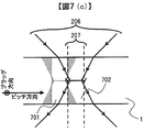
- Schematic diagram in the pitch direction showing a recording method according to an embodiment of the present invention.
- Schematic diagram in the pitch direction showing a region irradiated only with reference light in the recording method according to the embodiment of the present invention.
- Schematic diagram in the pitch direction showing a state in which the recording density is improved by the recording method according to the embodiment of the present invention.
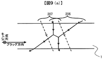
- Schematic representing a method of reproducing information from an optical information recording medium Schematic diagram in the Bragg direction representing a recording method according to an embodiment of the present invention
- Schematic representing the Bragg direction representing an area irradiated only with reference light in the recording method according to an embodiment of the present invention.
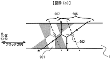
- Schematic diagram in the Bragg direction showing a state in which the recording density is improved by the recording method according to the embodiment of the present invention.
- FIG. 1 is a block diagram showing a recording / reproducing apparatus of an optical information recording medium for recording and / or reproducing digital information using holography.
- the optical information recording / reproducing device 10 is connected to an external control device 91 via an input / output control circuit 90.
- the optical information recording / reproducing apparatus 10 receives the information signal to be recorded from the external control device 91 by the input / output control circuit 90.
- the optical information recording / reproducing apparatus 10 transmits the reproduced information signal to the external control apparatus 91 by the input / output control circuit 90.
- the optical information recording / reproducing apparatus 10 includes a pickup 11, a reproduction reference light optical system 12, a cure optical system 13, a disk rotation angle detection optical system 14, and a rotation motor 50.
- the optical information recording medium 1 is a rotation motor. 50 can be rotated.
- the pickup 11 plays a role of emitting reference light and signal light to the optical information recording medium 1 and recording digital information on the recording medium using holography.
- the information signal to be recorded is sent by the controller 89 to the spatial light modulator in the pickup 11 via the signal generation circuit 86, and the signal light is modulated by the spatial light modulator.
- the reproduction reference light optical system 12 When reproducing the information recorded on the optical information recording medium 1, the reproduction reference light optical system 12 generates a light wave that causes the reference light emitted from the pickup 11 to enter the optical information recording medium in a direction opposite to that during recording. Generate. Reproduction light reproduced by the reproduction reference light is detected by a photodetector (to be described later) in the pickup 11, and a signal is reproduced by the signal processing circuit 85.
- the irradiation time of the reference light and the signal light applied to the optical information recording medium 1 can be adjusted by controlling the opening / closing time of the shutter in the pickup 11 via the shutter control circuit 87 by the controller 89.
- the cure optical system 13 plays a role of generating a light beam used for pre-cure and post-cure of the optical information recording medium 1.
- Precure is a pre-process for irradiating a predetermined light beam in advance before irradiating the desired position with reference light and signal light when recording information at a desired position in the optical information recording medium 1.
- Post-cure is a post-process for irradiating a predetermined light beam after recording information at a desired position in the optical information recording medium 1 so that additional recording cannot be performed at the desired position.
- the disk rotation angle detection optical system 14 is used to detect the rotation angle of the optical information recording medium 1.
- a signal corresponding to the rotation angle is detected by the disk rotation angle detection optical system 14, and a disk rotation motor control circuit is detected by the controller 89 using the detected signal.
- the rotation angle of the optical information recording medium 1 can be controlled via 88.
- a predetermined light source driving current is supplied from the light source driving circuit 82 to the light sources in the pickup 11, the cure optical system 13, and the disk rotation angle detection optical system 14, and each light source emits a light beam with a predetermined light amount. Can do.
- the pickup 11 and the disc cure optical system 13 are provided with a mechanism capable of sliding the position in the radial direction of the optical information recording medium 1, and the position is controlled via the access control circuit 81.
- the recording technology using the principle of angle multiplexing of holography tends to have a very small tolerance for the deviation of the reference beam angle.
- a mechanism for detecting the deviation amount of the reference beam angle is provided in the pickup 11, a servo control signal is generated by the servo signal generation circuit 83, and the deviation amount is corrected via the servo control circuit 84. It is necessary to provide a servo mechanism for this purpose in the optical information recording / reproducing apparatus 10.
- the pickup 11, the cure optical system 13, and the disk rotation angle detection optical system 14 may be simplified by combining several optical system configurations or all optical system configurations into one.
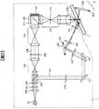
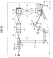
- FIG. 2 shows a recording principle in an example of a basic optical system configuration of the pickup 11 in the optical information recording / reproducing apparatus 10.
- the light beam emitted from the light source 201 passes through the collimator lens 202 and enters the shutter 203.
- the optical element 204 composed of, for example, a half-wave plate or the like, adjusts the light quantity ratio of p-polarized light and s-polarized light to a desired ratio.
- the light beam enters a PBS (Polarization Beam Splitter) prism 205.
- PBS Polarization Beam Splitter
- the light beam that has passed through the PBS prism 205 functions as signal light 206, and after the light beam diameter is expanded by the beam expander 208, the light beam passes through the phase mask 209, the relay lens 210, and the PBS prism 211 and passes through the spatial light modulator 212. Is incident on.
- the signal light to which information is added by the spatial light modulator 212 reflects the PBS prism 211 and propagates through the relay lens 213 and the spatial filter 214. Thereafter, the signal light is condensed as a spherical wave on the optical information recording medium 1 by the objective lens 215.
- the light beam reflected from the PBS prism 205 works as reference light 207, and is set to a predetermined polarization direction according to recording or reproduction by the polarization direction conversion element 216, and then passes through the mirror 217, the mirror 218, and the iris 219. Then, the light enters the galvanometer mirror 220.
- the iris 219 is an aperture element that two-dimensionally limits the cross-sectional size of the reference beam 207. Therefore, it can be considered that the beam diameter of the reference light 207 after passing through the iris 219 is limited to a predetermined size. Further, the beam diameter of the reference beam 207 is determined by the size of the opening of the iris 219.
- a beam expander may be used instead of the iris.
- the reference light may be incident into the beam expander from the opposite direction to reduce the beam diameter of the reference light.
- the component limited by the iris in the reference light can also be used for recording the hologram, so that a recording operation can be performed in a shorter time.
- the angle of the galvanometer mirror 220 can be adjusted by the actuator 221, the incident angle of the reference light that enters the optical information recording medium 1 as a plane wave after passing through the lens 222 and the lens 223 can be set to a desired angle. it can.
- an element that converts the wavefront of the reference light may be used instead of the galvanometer mirror.
- the signal light and the reference light are incident on the optical information recording medium 1 so as to overlap each other, whereby an interference fringe pattern is formed in the recording medium, and information is recorded by writing this pattern on the recording medium.
- the incident angle of the reference light incident on the optical information recording medium 1 can be changed by the galvanometer mirror 220, recording by angle multiplexing is possible.
- holograms corresponding to each reference beam angle are called pages, and a set of pages angle-multiplexed in the same area is called a book. .
- FIG. 3 shows a reproduction principle in an example of a basic optical system configuration of the pickup 11 in the optical information recording / reproducing apparatus 10.
- the reference beam is incident on the optical information recording medium 1 and the light beam transmitted through the optical information recording medium 1 is reflected by the galvanometer mirror 225 whose angle can be adjusted by the actuator 224 as described above. By doing so, the reproduction reference light is generated.
- the reproduction light reproduced by the reproduction reference light propagates through the objective lens 215, the relay lens 213, and the spatial filter 214. Thereafter, the reproduction light passes through the PBS prism 211 and enters the photodetector 226, and the recorded signal can be reproduced.
- an image sensor such as a CMOS image sensor or a CCD image sensor can be used as the photodetector 226.
- any element may be used as long as page data can be reproduced.
- FIG. 4 shows an operation flow of recording and reproduction in the optical information recording / reproducing apparatus 10.
- a flow relating to recording / reproduction using holography in particular will be described.
- FIG. 4A shows an operation flow from the insertion of the optical information recording medium 1 into the optical information recording / reproducing apparatus 10 until the preparation for recording or reproduction is completed.
- FIG. FIG. 4C shows an operation flow until information is recorded on the information recording medium 1, and
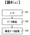
- FIG. 4C shows an operation flow until the information recorded on the optical information recording medium 1 is reproduced from the ready state.
- the optical information recording / reproducing apparatus 10 discriminates whether the inserted medium is a medium for recording or reproducing digital information using holography, for example. (402).
- the optical information recording / reproducing apparatus 10 reads control data provided on the optical information recording medium (403). ), For example, information relating to the optical information recording medium and information relating to various setting conditions during recording and reproduction, for example.
- the operation flow from the ready state to recording information is as follows. First, data to be recorded is received (411), and information corresponding to the data is received from the spatial light modulator in the pickup 11. To send.
- the access control circuit 81 is controlled to position the pickup 11 and the cure optical system 13 at predetermined positions on the optical information recording medium.
- the optical information recording medium 1 has address information, it reproduces the address information, checks whether it is positioned at the target position, and calculates the amount of deviation from the predetermined position if it is not positioned at the target position. And repeat the positioning operation.
- a predetermined region is pre-cured using the light beam emitted from the cure optical system 13 (414), and data is recorded using the reference light and signal light emitted from the pickup 11 (415).
- post cure is performed using the light beam emitted from the cure optical system 13 (416). Data may be verified as necessary.
- the operation flow from the ready state to the reproduction of the recorded information is as follows.
- the access control circuit 81 is controlled, and the pickup 11 and the reproduction reference light are reproduced.
- the position of the optical system 12 is positioned at a predetermined position on the optical information recording medium.
- the optical information recording medium 1 has address information, it reproduces the address information, checks whether it is positioned at the target position, and calculates the amount of deviation from the predetermined position if it is not positioned at the target position. And repeat the positioning operation.
- FIG. 5 shows a state in which the optical information recording medium 1 is irradiated with the signal light 206 and the reference light 207 and a plurality of pages are angle-multiplexed recorded. That is, FIG. 5 shows the state of the signal light 206, the reference light 207, and the optical information recording medium 1 during the processing of the data recording 615 in FIG.
- the incident angle of the reference beam 207 irradiated on the optical information recording medium 1 is sequentially changed according to the page to be recorded. For example, when the first page is recorded, the signal light 206 and the reference light 207a are simultaneously irradiated, and when the second page is recorded, the signal light 206 and the reference light 207b are simultaneously irradiated.
- One book 501 is recorded.
- the direction in which the incident angle of the reference light is changed is called the Bragg direction
- the direction orthogonal to the Bragg direction is called the pitch direction.
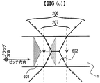
- 6 (a), 6 (b), and 6 (c) are cross-sectional views of the optical information recording medium 1 irradiated with the signal light 206 and the reference light 207 at the time of page recording in the prior art when viewed from the Bragg direction. is there.
- FIG. 6A in the prior art, in order to record a hologram having a stable reproduction quality, all signal light 206 transmitted through the optical information recording medium 1 is irradiated so as to overlap with the reference light 207. It was.
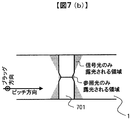
- FIGS. 7A, 7B, and 7C a part of the signal light 206 that passes through the optical information recording medium 1 is left behind as a hologram. A method of recording is described.
- the beam diameter or beam width refers to the diameter or beam width of the beam irradiated on the recording surface of the optical information recording medium.
- FIG. 7C shows a state in which the book 702 and the book 702 are recorded at a distance that does not overlap each other when the cross section of the optical information recording medium 1 is viewed from the Bragg direction. In order to improve the density, the book may be recorded at a distance where the book 701 and the book 702 overlap each other.
- the recording interval of each book is such that the beam waists of the signal light 206 do not overlap each other when viewed from the thickness direction of the optical information recording medium.
- the recording density can be improved even if recording is performed at a recording interval such that the beam waists of adjacent holograms overlap each other.
- the width of the beam of the reference light 207 irradiated on the optical information recording medium 1 is desirably larger than the width of the beam waist of the signal light 206 as shown in FIGS. This is because when the beam diameter in the pitch direction of the reference light is smaller than the width of the beam waist of the signal light 206, only a part of the spatial frequency component of the signal light image is recorded, and the reproduction quality is stabilized. This is because the hologram cannot be recorded.
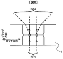
- FIG. 8 shows a state in which the reference light 207c is irradiated onto the optical information recording medium 1 and the signal light 206c is reproduced from the hologram recorded using the recording method of FIG. That is, FIG. 8 shows the state of the reference light 207 and the optical information recording medium 1 and the reproduced signal light 206 during the processing of the data reproduction 422 in FIG.
- the reference light irradiated at the time of reproduction is reflected by the mirror 225 and irradiated to the optical information recording medium 1 in the direction opposite to that at the time of recording.
- the reproduced signal light 206 c travels back through the optical element that has passed during recording and reaches the photodetector 226.
- the wasteful consumption of M / # of the recording material can be suppressed, and recording can be performed by reducing the interval between the books. Therefore, high-density recording can be realized.
- the signal light 206 is irradiated so that the beam waist of the signal light 206 is located inside the optical information recording medium 1.
- the beam waist is located outside the optical information recording medium 1. Even if irradiation is performed in this manner, similarly to the present embodiment, it is possible to suppress the wasteful consumption of M / # of the recording material and to obtain an effect that enables recording by reducing the interval between the books.
- FIGS. 9A, 9B, and 9C are cross-sectional views of the optical information recording medium 1 irradiated with the signal light 206 and the reference light 207 during page recording as viewed from the pitch direction.
- the beam diameter of the reference light is changed as compared with the conventional method.
- the beam diameter in the Bragg direction of the reference light 207 is changed to a predetermined value using an iris 219, and the signal light 206 transmitted through the optical information recording medium 1 is transmitted. Record a book with extra parts.
- this recording method as shown in FIG. 9B, there are areas where only signal light is exposed and areas where only reference light is exposed in the recording area near the book 901.
- the size of the area where only the signal light or the reference light is exposed is smaller than the conventional method of recording a book by irradiating the reference light so as to include all the signal light. / # Wasteful consumption is suppressed.
- the recording density when the recording density is improved by reducing the distance between the book 901 and the book 902, the M / # of the recording medium that can be used in the recording area of the book 902 is all signal light. Therefore, the recording density can be improved by increasing the number of possible multiplexing.
- the recording density is further improved as compared with the first embodiment in that wasteful consumption of M / # of the recording medium is suppressed not only in the pitch direction but also in the Bragg direction in the recording area near the book. It becomes possible to make it.
- the reference light beam diameter in the Bragg direction is variable according to the reference light angle. Except for the part where the size of the iris opening is variable, the other configuration is the same as that of the second embodiment, and thus the description thereof is omitted.
- the beam diameter of the reference light in the Bragg direction when the beam diameter of the reference light in the Bragg direction is changed and the page is angle-multiplexed, the beam diameter of the reference light applied to the medium changes according to the reference light angle. There is a problem of doing. Therefore, by changing the beam diameter of the reference light according to the reference light angle, the beam diameter of the reference light that contributes to hologram recording can be made the same even if the reference light angle changes.
- FIG. 10 shows another form of FIG. 2, and an iris actuator 219a for controlling the opening size of the iris 219 is added.
- the iris actuator 219a controls the opening size of the iris 219 according to the reference light angle when recording a page.
- the iris actuator 219a sets the opening size of the iris 219 to a predetermined value regardless of the reference light angle.
- FIG. 11 shows an example of the relationship between the reference light angle for recording a page and the optimum reference light beam diameter change rate.
- the reference light beam diameter change rate is changed according to the reference light angle using the iris 219 and the iris actuator 219a, even if the reference light angle changes due to the angle multiplex recording of the page, Unnecessary consumption of M / # in the recording area near the book can be suppressed.
- FIG. 12 shows a flowchart for sequentially recording pages while changing the reference light beam diameter changing rate according to the reference light incident angle. That is, FIG. 12 describes details of the data recording process 415.
- the reference light incident angle is set to the incident angle for recording the first page. (1203).
- the aperture size of the iris 219 is controlled by the iris actuator 219a so that the reference beam diameter change rate corresponding to the reference beam incident angle set in 1203 is obtained (1204). Then, the optical information recording medium 1 is irradiated with the signal light 206 and the reference light 207 set to a reference light beam diameter change rate of a predetermined value (1205), and a page is recorded.
- the above method can be used to realize hologram recording with stable reproduction quality. It is superior to the method described in 1.
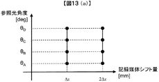
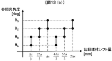
- FIGS. 13A and 13B show the relationship between the shift amount of the recording medium and the reference light angle range used for page recording when a plurality of books are recorded side by side on the recording medium.
- FIG. 13 (a) when a plurality of books are recorded with an interval of each book as ⁇ x, pages are recorded in the range of reference light angles ⁇ A to ⁇ D by shifting the recording medium by ⁇ x. It was.
- the reference beam angle range for recording a page is divided into three sections of ⁇ A to ⁇ B, ⁇ B to ⁇ C, and ⁇ C to ⁇ D, and the book is created by shifting the recording medium by ⁇ x / 3.
- the M / # consumption in the recording area is reduced, and as a result, a reproduction light intensity greater than that in FIG. 13A can be obtained.
- This technique is called a short stack, and is disclosed in Japanese Translation of PCT International Publication No. 2010-508617.
- the reference light beam diameter change rate may be set as shown in FIG.
- the reference light angle range for recording a page is divided into three sections of ⁇ A to ⁇ B, ⁇ B to ⁇ C, and ⁇ C to ⁇ D, the reference light beam diameter change rate is uniformly given in each section.
- this method can simplify the control of the iris actuator 219a and divides the shift amount of the recording medium. This is superior to the method of Example 3 in that the M / # consumption of the recording medium is reduced.
- the reproducing operation is performed by expanding the beam diameter of the reference light from the time of recording during book reproduction. Except for the point where the opening size of the iris 219 at the time of reproduction is controlled to be larger than that at the time of recording, the other configuration is the same as that of the third embodiment, and thus the description thereof is omitted.
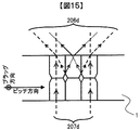
- FIG. 15 shows another form of FIG. FIG. 15 shows how the signal light 206d is reproduced by irradiating the reference light 207d with a beam diameter different from that during recording.
- the reference beam 207d has a larger beam diameter than the reference beam 207c having the same beam size as that during recording.
- the iris actuator 219a is controlled during reproduction.
- a beam expander may be used instead of the iris in order to expand the beam diameter of the reference light.
- the reference light is allowed to enter the beam expander in the forward direction to enlarge the beam diameter of the reference light.
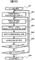
- FIG. 16 shows a flowchart for performing the reproducing operation by expanding the opening size of the iris 219 by the iris actuator 219a during reproduction. That is, FIG. 16 describes details of the data reproduction processing 422.
- the reference light incident angle is set to the incident angle for reproducing the first page. (1603).
- the opening size of the iris 219 is controlled by the iris actuator 219a so that the reference light beam diameter becomes a predetermined value larger than that during recording (1604). Then, the optical information recording medium 1 is irradiated with reference light 207 set to a predetermined beam diameter (1605), the page is reproduced, and at 1606, the reproduced image is acquired by a photodetector.
- FIG. 17 shows the relationship between the incident angle of the reference light and the amount of light received by the photodetector when the page is reproduced while changing the incident angle of the reference light with respect to the optical information recording medium by paying attention to one specific page in the book.
- the amount of light received by the photodetector takes a maximum value when the incident angle of the reference light is optimum, and gradually decreases as the deviation amount of the incident angle of the reference light increases.
- the maximum value of the amount of light received by the photodetector is defined as the signal amplitude
- the minimum value is defined as the noise amplitude.
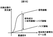
- FIG. 18 shows the relationship between the signal amplitude and the noise amplitude when the reference light beam diameter during reproduction is changed.
- the signal component is defined as a value obtained by subtracting the noise amplitude from the signal amplitude.
- the noise amplitude increases in proportion to the reference light beam diameter, whereas the increase in the signal component obtained by subtracting the noise amplitude from the signal amplitude results in a predetermined reference light beam diameter. Saturates with value. This saturation occurs because the reference light beam diameter eventually exceeds the size of the recording hologram as the reference light beam diameter is increased.
- the noise amplitude is generated when the in-plane reflected light of the optical information recording medium leaks into the photodetector, it is desirable to perform reproduction with the reflected light that is the main cause of noise as small as possible.
- FIG. 19 shows a flowchart of a reproducing operation for optimally controlling the size of the reference light beam diameter according to the incident angle of the reference light during reproduction. That is, FIG. 19 describes details of the data reproduction processing 422.
- the reference light incident angle is set to the incident angle for reproducing the first page. (1903).
- the aperture size of the iris 219 is controlled by the iris actuator 219a so that the signal beam diameter with respect to the noise amplitude on the photodetector becomes the maximum (1904).
- the optical information recording medium 1 is irradiated with reference light 207 set to an optimum beam diameter in signal reproduction (1905), a page is reproduced, and in 1906, the reproduced image is acquired by a photodetector.
- the reproduction operation is performed using the above method, the influence of the noise amplitude on the signal amplitude can be minimized, and the reproduction operation can be performed with higher signal quality. Therefore, the reproduction operation is superior to the method described in the fifth embodiment. ing.
- this invention is not limited to the above-mentioned Example, Various modifications are included.
- the above-described embodiments have been described in detail for easy understanding of the present invention, and are not necessarily limited to those having all the configurations described. It is also possible to add the configuration of another embodiment to the configuration of one embodiment. Further, it is possible to add, delete, and replace other configurations for a part of each embodiment.
- each of the above-described configurations may be configured such that a part or all of the configuration is configured by hardware, or is realized by executing a program by a processor.
- control lines and information lines indicate what is considered necessary for the explanation, and not all control lines and information lines are necessarily shown in the product. In practice, it can be considered that almost all the components are connected to each other.
- SYMBOLS 1 Optical information recording medium, 10 ... Optical information recording / reproducing apparatus, 11 ... Pickup, 12 ... Reference optical system for reproduction
- Phase mask 210 ... ⁇ Relay 211 ... PBS prism, 212 ... spatial light modulator, 213 ... relay lens, 214 ... spatial filter, 215 ... objective lens, 216 ... polarization direction conversion element, 217, 218 ... mirror, 219 ... iris, 219a ... iris actuator, 220 ... galvanometer mirror, 221 ... actuator, 222, 223 ... lens, 224 ... actuator, 225 ... Galvano mirror, 226, photodetector, 501, 601, 602, 701, 702, 901, 902, book
Landscapes
- Physics & Mathematics (AREA)
- General Physics & Mathematics (AREA)
- Optics & Photonics (AREA)
- Optical Recording Or Reproduction (AREA)
- Holo Graphy (AREA)
- Optical Head (AREA)
Abstract
Description
Claims (19)
- 信号光と参照光の干渉を利用して光情報記録媒体に情報を記録する光情報記録装置であって、
前記光情報記録媒体に光を出射する光源と、
前記光源から出射された出射光を前記信号光と前記参照光に分割する光分割素子と、
前記光情報記録媒体に対する前記参照光の入射角度を制御する参照光角度制御部と、
前記信号光を球面波として前記光情報記録媒体に照射する信号光光学系と、
前記参照光を平面波として前記光情報記録媒体に照射する参照光光学系と、
を備え、
前記光情報記録媒体に対して前記参照光の入射角度が変化する方向である第一の方向から前記光情報記録媒体を見た場合に、前記光情報媒体の内部に、前記信号光が露光される領域と、前記参照光が露光される領域と、前記信号光および前記参照光が重複して露光される領域と、が存在するよう前記信号光と前記参照光を照射することで情報を記録する、光情報記録装置。 - 請求項1に記載の光情報記録装置であって、
前記第一の方向から前記光情報記録媒体を見た場合に、前記光情報記録媒体の記録面に対して照射された前記参照光の光束の幅は、前記光情報記録媒体の表面上での信号光の光束の幅よりも小さく、かつ、前記信号光のビームウェストの幅よりも大きいこと、を特徴とする光情報記録装置。 - 請求項1または2に記載の光情報記録装置であって、
前記信号光のビームウェストが前記光情報記録媒体の内部に存在するように前記信号光が照射されること、を特徴とする光情報記録装置。 - 請求項1に記載の光情報記録装置であって、
前記光分割素子で分割された参照光が入射する光学素子、を備え、
前記光学素子で光束径が縮小された参照光が前記光情報記録媒体に照射されること、を特徴とする光情報記録装置。 - 請求項1に記載の光情報記録装置であって、
前記第一の方向から前記光情報記録媒体を見た場合に、前記信号光および前記参照光が重複して露光される領域が、前記信号光が露光される領域に挟まれた配置であること、を特徴とする光情報記録装置。 - 請求項1に記載の光情報記録装置であって、
前記第一の方向と直交する第二の方向から前記光情報記録媒体を見た場合に、前記信号光および前記参照光が重複して露光される領域が、前記信号光が露光される領域に挟まれた配置であること、を特徴とする光情報記録装置。 - 請求項6に記載の光情報記録装置であって、
前記光情報記録装置は、前記参照光の光束の幅を制御する参照光光束径制御部を備え、
前記参照光光束径制御部は、前記参照光の入射角度に応じて前記参照光の光束の幅を変化させること、を特徴とする光情報記録装置。 - 請求項6に記載の光情報記録装置であって、
前記参照光の光束径の大きさは、前記参照光の入射角度に応じて変更されること、を特徴とする光情報記録装置。 - 請求項7に記載の光情報記録装置であって、
前記参照光の光束径の大きさは、前記参照光の入射角度に応じて段階的に変更されること、を特徴とする光情報記録装置。 - 請求項1に記載の光情報記録装置であって、
前記信号光と前記参照光を干渉させて生成される第一のホログラムは、前記第一のホログラムと異なる第二のホログラムの一部と重複するように生成されること、を特徴とする光情報記録装置。 - 信号光と参照光の干渉を利用して光情報記録媒体に情報を記録するための情報記録方法であって、
前記光情報記録媒体に光を出射するステップと、
前記光源から出射された出射光を前記信号光と前記参照光に分割するステップと、
前記光情報記録媒体に対する前記参照光の入射角度を制御するステップと、
前記信号光を球面波として前記光情報記録媒体に照射するステップと、
前記参照光を平面波として前記光情報記録媒体に照射するステップと、
前記光情報記録媒体に対して前記参照光の入射角度が変化する方向である第一の方向から前記光情報記録媒体を見た場合に、前記光情報記録媒体の内部に、前記信号光が露光される領域と、前記参照光が露光される領域と、前記信号光および前記参照光が重複して露光される領域と、が存在するよう前記信号光および前記参照光を照射して情報を記録するステップと、
を有する情報記録方法。 - 信号光と参照光の干渉を利用して光情報記録媒体に情報を記録するための情報記録方法であって、
前記光情報記録媒体に光を出射するステップと、
前記光源から出射された出射光を前記信号光と前記参照光に分割するステップと、
前記光情報記録媒体に対する前記参照光の入射角度を制御するステップと、
前記信号光を球面波として前記光情報記録媒体に照射するステップと、
前記参照光を平面波として前記光情報記録媒体に照射するステップと、
を有し、
前記参照光を前記光情報記録媒体に照射するステップでは、前記光情報記録媒体に対して前記参照光の入射角度が変化する方向である第一の方向から前記光情報記録媒体を見た場合に、前記光情報記録媒体の記録面に対して照射する前記参照光の光束の幅を、前記光情報記録媒体の表面上での前記信号光の光束の幅よりも小さく、かつ、前記信号光のビームウェストの幅よりも大きくなるよう照射する、を特徴とする光情報記録方法。 - 請求項11に記載の情報記録方法であって、
前記信号光のビームウェストが前記光情報記録媒体の内部に存在するように前記信号光が照射されること、を特徴とする情報記録方法。 - 請求項11に記載の情報記録方法であって、
前記情報を記録するステップでは、前記第一の方向から前記光情報記録媒体を見た場合に、前記信号光および前記参照光が重複して露光される領域が、前記信号光が露光される領域に挟まれた配置となるように前記信号光および前記参照光を照射すること、を特徴とする情報記録方法。 - 請求項11に記載の情報記録方法であって、
前記情報を記録するステップでは、前記第一の方向と直交する第二の方向から前記光情報記録媒体を見た場合に、前記信号光および前記参照光が重複して露光される領域が、前記信号光が露光される領域に挟まれた配置となるように前記信号光および前記参照光を照射すること、を特徴とする情報記録方法。 - 請求項11に記載の情報記録方法であって、
前記情報記録再生方法は、前記参照光の光束の幅を変更するステップを備え、
前記参照光の光束の幅を変更するステップは、前記参照光の入射角度に応じて前記参照光の光束の大きさを変化させること、を特徴とする情報記録方法。 - 請求項11に記載の情報記録方法であって、
前記情報記録再生方法は、前記参照光の光束の大きさを変更するステップを備え、
前記参照光の光束径の大きさを変更するステップは、前記参照光の入射角度に応じて前記参照光の光束の幅を変化させること、を特徴とする情報記録方法。 - 請求項16に記載の情報記録方法であって、
前記参照光の光束の幅を変更するステップは、前記参照光の入射角度に応じて前記参照光の光束の幅を段階的に変化させること、を特徴とする情報記録方法。 - 請求項11に記載の情報記録方法であって、
前記信号光と前記参照光を干渉させて生成される第一のホログラムは、前記第一のホログラムと異なる第二のホログラムの一部と重複するように生成されること、を特徴とする情報記録方法。
Priority Applications (4)
| Application Number | Priority Date | Filing Date | Title |
|---|---|---|---|
| US15/320,766 US20170162221A1 (en) | 2014-06-25 | 2014-06-25 | Optical Information Recording/Reproduction Device and Optical Information Recording/Reproduction Method |
| CN201480078148.5A CN106233388A (zh) | 2014-06-25 | 2014-06-25 | 光信息记录再生装置以及光信息记录再生方法 |
| PCT/JP2014/066761 WO2015198407A1 (ja) | 2014-06-25 | 2014-06-25 | 光情報記録再生装置、及び光情報記録再生方法 |
| JP2016528796A JPWO2015198407A1 (ja) | 2014-06-25 | 2014-06-25 | 光情報記録再生装置、及び光情報記録再生方法 |
Applications Claiming Priority (1)
| Application Number | Priority Date | Filing Date | Title |
|---|---|---|---|
| PCT/JP2014/066761 WO2015198407A1 (ja) | 2014-06-25 | 2014-06-25 | 光情報記録再生装置、及び光情報記録再生方法 |
Publications (1)
| Publication Number | Publication Date |
|---|---|
| WO2015198407A1 true WO2015198407A1 (ja) | 2015-12-30 |
Family
ID=54937542
Family Applications (1)
| Application Number | Title | Priority Date | Filing Date |
|---|---|---|---|
| PCT/JP2014/066761 Ceased WO2015198407A1 (ja) | 2014-06-25 | 2014-06-25 | 光情報記録再生装置、及び光情報記録再生方法 |
Country Status (4)
| Country | Link |
|---|---|
| US (1) | US20170162221A1 (ja) |
| JP (1) | JPWO2015198407A1 (ja) |
| CN (1) | CN106233388A (ja) |
| WO (1) | WO2015198407A1 (ja) |
Families Citing this family (2)
| Publication number | Priority date | Publication date | Assignee | Title |
|---|---|---|---|---|
| EP3461636B1 (en) * | 2017-09-29 | 2021-05-19 | Wayray AG | Laminated holographic display and manufacturing thereof |
| US11443448B2 (en) * | 2019-12-03 | 2022-09-13 | Samsung Electronics Co., Ltd. | Incoherent digital holography based depth camera |
Citations (7)
| Publication number | Priority date | Publication date | Assignee | Title |
|---|---|---|---|---|
| JP2001147634A (ja) * | 1999-11-22 | 2001-05-29 | Sony Corp | ホログラムの多重記録方法及びホログラム記録装置 |
| JP2005215381A (ja) * | 2004-01-30 | 2005-08-11 | Pioneer Electronic Corp | ホログラム記録担体、記録再生方法及び記録再生装置 |
| JP2006023445A (ja) * | 2004-07-07 | 2006-01-26 | Sony Corp | ホログラム記録装置及びホログラム記録方法 |
| JP2009103765A (ja) * | 2007-10-19 | 2009-05-14 | Hitachi Ltd | 光情報記媒体、光情報記録再生装置、及び光情報記録再生方法 |
| WO2009099100A1 (ja) * | 2008-02-05 | 2009-08-13 | Sharp Kabushiki Kaisha | 情報記録媒体、情報記録装置、情報再生装置、情報記録方法、情報再生方法および2次元情報作成方法 |
| JP2010129110A (ja) * | 2008-11-26 | 2010-06-10 | Hitachi Ltd | 光情報再生装置、光情報記録再生装置 |
| JP2012221520A (ja) * | 2011-04-06 | 2012-11-12 | Hitachi Consumer Electronics Co Ltd | 光情報再生装置、光情報記録再生装置 |
Family Cites Families (3)
| Publication number | Priority date | Publication date | Assignee | Title |
|---|---|---|---|---|
| US7092133B2 (en) * | 2003-03-10 | 2006-08-15 | Inphase Technologies, Inc. | Polytopic multiplex holography |
| US7589877B2 (en) * | 2005-12-02 | 2009-09-15 | Inphase Technologies, Inc. | Short stack recording in holographic memory systems |
| JP2012211801A (ja) * | 2011-03-31 | 2012-11-01 | Tdk Corp | ホログラム画像記録媒体の評価方法及び評価装置 |
-
2014
- 2014-06-25 WO PCT/JP2014/066761 patent/WO2015198407A1/ja not_active Ceased
- 2014-06-25 JP JP2016528796A patent/JPWO2015198407A1/ja active Pending
- 2014-06-25 US US15/320,766 patent/US20170162221A1/en not_active Abandoned
- 2014-06-25 CN CN201480078148.5A patent/CN106233388A/zh active Pending
Patent Citations (7)
| Publication number | Priority date | Publication date | Assignee | Title |
|---|---|---|---|---|
| JP2001147634A (ja) * | 1999-11-22 | 2001-05-29 | Sony Corp | ホログラムの多重記録方法及びホログラム記録装置 |
| JP2005215381A (ja) * | 2004-01-30 | 2005-08-11 | Pioneer Electronic Corp | ホログラム記録担体、記録再生方法及び記録再生装置 |
| JP2006023445A (ja) * | 2004-07-07 | 2006-01-26 | Sony Corp | ホログラム記録装置及びホログラム記録方法 |
| JP2009103765A (ja) * | 2007-10-19 | 2009-05-14 | Hitachi Ltd | 光情報記媒体、光情報記録再生装置、及び光情報記録再生方法 |
| WO2009099100A1 (ja) * | 2008-02-05 | 2009-08-13 | Sharp Kabushiki Kaisha | 情報記録媒体、情報記録装置、情報再生装置、情報記録方法、情報再生方法および2次元情報作成方法 |
| JP2010129110A (ja) * | 2008-11-26 | 2010-06-10 | Hitachi Ltd | 光情報再生装置、光情報記録再生装置 |
| JP2012221520A (ja) * | 2011-04-06 | 2012-11-12 | Hitachi Consumer Electronics Co Ltd | 光情報再生装置、光情報記録再生装置 |
Non-Patent Citations (1)
| Title |
|---|
| MASAKAZU OGASAWARA: "Hologram Memory System", OPTICAL MEMORY AND ITS SYSTEMS FOR NEXT GENERATION, 31 January 2009 (2009-01-31), pages 192 - 193 * |
Also Published As
| Publication number | Publication date |
|---|---|
| CN106233388A (zh) | 2016-12-14 |
| US20170162221A1 (en) | 2017-06-08 |
| JPWO2015198407A1 (ja) | 2017-05-25 |
Similar Documents
| Publication | Publication Date | Title |
|---|---|---|
| CN102385874B (zh) | 再现装置和再现方法 | |
| JP5183667B2 (ja) | 再生装置および再生方法 | |
| JP5581111B2 (ja) | 光情報再生装置および光情報再生方法 | |
| US8472298B2 (en) | Optical information recording and reproducing apparatus and optical information recording method | |
| US8085643B2 (en) | Optical information reproducing apparatus, optical information recording and reproducing apparatus | |
| US9081364B2 (en) | Optical information recording/reproducing apparatus, optical information recording/reproducing method, and optical information recording medium | |
| WO2015198407A1 (ja) | 光情報記録再生装置、及び光情報記録再生方法 | |
| JP5320343B2 (ja) | 光情報記録再生装置及び光情報記録再生方法 | |
| JP5104695B2 (ja) | 情報記録装置 | |
| JP5557787B2 (ja) | 光情報再生装置、光情報記録再生装置 | |
| JP5816132B2 (ja) | ホログラム用光ピックアップ装置及び光情報記録再生装置 | |
| JP2007010821A (ja) | ホログラム装置及びホログラム記録再生方法 | |
| JP2006344278A (ja) | ホログラム装置及びホログラム記録再生方法 | |
| US8077580B2 (en) | Optical information recording and reproducing apparatus | |
| JP2006259519A (ja) | ホログラム記録装置 | |
| US20160358623A1 (en) | Optical information recording/reproducing device and optical information recording/reproducing method | |
| JP2012069207A (ja) | ホログラフィを用いたホログラフィックメモリ | |
| JP2018137029A (ja) | ホログラム記録再生装置 | |
| WO2016199229A1 (ja) | ホログラム記録再生装置 | |
| JP2012133879A (ja) | 情報記録装置、情報再生装置および記録媒体 | |
| JP2012243355A (ja) | 光情報記録再生装置および光情報記録再生方法 | |
| JP2015130215A (ja) | 光情報記録装置および光情報記録方法 | |
| JP2016207246A (ja) | 光情報記録再生装置 | |
| WO2016017020A1 (ja) | 光情報記録再生方法、光情報記録再生装置 | |
| WO2016208047A1 (ja) | 光位相制御装置、光位相制御方法、光情報記録再生装置、及び光情報記録再生方法 |
Legal Events
| Date | Code | Title | Description |
|---|---|---|---|
| 121 | Ep: the epo has been informed by wipo that ep was designated in this application |
Ref document number: 14895907 Country of ref document: EP Kind code of ref document: A1 |
|
| ENP | Entry into the national phase |
Ref document number: 2016528796 Country of ref document: JP Kind code of ref document: A |
|
| WWE | Wipo information: entry into national phase |
Ref document number: 15320766 Country of ref document: US |
|
| NENP | Non-entry into the national phase |
Ref country code: DE |
|
| 122 | Ep: pct application non-entry in european phase |
Ref document number: 14895907 Country of ref document: EP Kind code of ref document: A1 |