WO2015194351A1 - ブレーキ装置 - Google Patents
ブレーキ装置 Download PDFInfo
- Publication number
- WO2015194351A1 WO2015194351A1 PCT/JP2015/065746 JP2015065746W WO2015194351A1 WO 2015194351 A1 WO2015194351 A1 WO 2015194351A1 JP 2015065746 W JP2015065746 W JP 2015065746W WO 2015194351 A1 WO2015194351 A1 WO 2015194351A1
- Authority
- WO
- WIPO (PCT)
- Prior art keywords
- hydraulic pressure
- cylinder hydraulic
- wheel
- request
- brake
- Prior art date
- Legal status (The legal status is an assumption and is not a legal conclusion. Google has not performed a legal analysis and makes no representation as to the accuracy of the status listed.)
- Ceased
Links
Images


Classifications
-
- B—PERFORMING OPERATIONS; TRANSPORTING
- B60—VEHICLES IN GENERAL
- B60T—VEHICLE BRAKE CONTROL SYSTEMS OR PARTS THEREOF; BRAKE CONTROL SYSTEMS OR PARTS THEREOF, IN GENERAL; ARRANGEMENT OF BRAKING ELEMENTS ON VEHICLES IN GENERAL; PORTABLE DEVICES FOR PREVENTING UNWANTED MOVEMENT OF VEHICLES; VEHICLE MODIFICATIONS TO FACILITATE COOLING OF BRAKES
- B60T8/00—Arrangements for adjusting wheel-braking force to meet varying vehicular or ground-surface conditions, e.g. limiting or varying distribution of braking force
- B60T8/17—Using electrical or electronic regulation means to control braking
Definitions
- the present invention relates to a brake control device that applies a braking force to a vehicle.
- An object of the present invention is to provide a brake device capable of controlling a master cylinder pressure in which both driver operation and control regarding vehicle behavior are compatible.
- an upstream brake hydraulic pressure generating device that generates a master cylinder hydraulic pressure by multiplying a brake operating force of a brake operating member operated by a driver.
- a downstream brake fluid pressure generator capable of controlling the pressure in the wheel cylinder fluid pressure by driving the pump and the control valve, calculating the driver target fluid pressure according to the operation state of the brake operation member, and Alternatively, the required foil cylinder hydraulic pressure is calculated according to the state of the wheels, and the required master cylinder hydraulic pressure is calculated based on at least the calculated driver target hydraulic pressure and the calculated required foil cylinder hydraulic pressure.
- FIG. 2 is a view showing a schematic configuration of a brake device of Example 1 together with a hydraulic circuit.
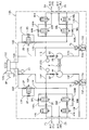
- FIG. 2 is a hydraulic circuit diagram of a downstream brake hydraulic pressure generating device.
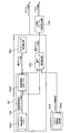
- FIG. 6 is a control block diagram showing a brake fluid pressure control process of the first embodiment.
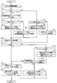
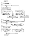
- FIG. 6 is a flowchart showing calculation processing of a wheel cylinder hydraulic pressure and a master cylinder hydraulic pressure according to the first embodiment.
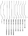
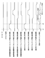
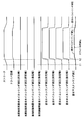
- FIG. 10 is a time chart in the case where control according to the driver's brake pedal operation is performed without performing control such as VDC, ABS, TCS and BAS in the brake system of the first embodiment.
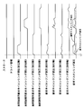
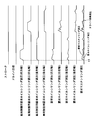
- 5 is a time chart showing wheel cylinder hydraulic pressure control and master cylinder hydraulic pressure control when ABS is performed in the brake system of the first embodiment.
- FIG. 1 is a view showing a schematic configuration of a brake device of Example 1 together with a hydraulic circuit.
- FIG. 2 is a hydraulic circuit diagram of a downstream brake hydraulic pressure generating device.
- FIG. 6 is a control
- FIG. 7 is a schematic view illustrating a method of setting a predetermined value to be added to the required master cylinder fluid pressure in the ABS of the first embodiment.
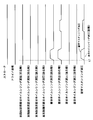
- 5 is a time chart showing wheel cylinder hydraulic pressure control and master cylinder hydraulic pressure control when VDC is performed in the brake system of the first embodiment.
- FIG. 6 is a time chart showing wheel cylinder hydraulic pressure control and master cylinder hydraulic pressure control when ABS is performed when VDC is performed in the brake system of the first embodiment. It is a time chart showing foil cylinder liquid pressure control and master cylinder liquid pressure control in case TCS is performed in a brake device of Example 1.
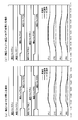
- 5 is a time chart showing the hydraulic pressure state of the wheel cylinder W / C of each wheel in the VDC of the first embodiment.
- FIG. 7 is a flowchart showing calculation processing of a wheel cylinder hydraulic pressure and a master cylinder hydraulic pressure according to a second embodiment.
- FIG. 13 is a time chart showing wheel cylinder hydraulic pressure control and master cylinder hydraulic pressure control when ABS is performed when VDC is performed in the brake system of the second embodiment.
- FIG. 1 is a diagram showing a schematic configuration of a brake system of a first embodiment together with a hydraulic circuit.
- the brake system of the first embodiment is an example applied to a rear wheel drive vehicle, but may be applied to a front wheel drive vehicle or a four wheel drive vehicle, and is not particularly limited.
- the brake device is a wheel cylinder W / C (FL), W / C (FR), W / C (RL), W / C (RR) (hereinafter collectively referred to as "all”) provided at each wheel FL to RR of the vehicle.
- Fluid pressure braking force is applied to each of the wheels FL to RR by supplying a brake fluid as a working fluid to the wheel cylinder W / C to generate a brake fluid pressure (foil cylinder fluid pressure).
- the brake actuation unit including the wheel cylinder W / C is a so-called disc type, and is provided with a brake disc rotating integrally with the tire and a caliper (hydraulic brake caliper) provided with a brake pad.
- the brake system has brake pipings 107 and 108 of two systems (primary P system and secondary S system), and adopts, for example, an X piping system. In addition, you may employ
- P and S are added to the end of the respective reference numerals.
- the brake device includes an upstream brake fluid pressure generating device 100 capable of controlling the master cylinder fluid pressure, and a downstream brake fluid pressure generating device 105 capable of controlling the wheel cylinder fluid pressure of each wheel.
- the upstream brake hydraulic pressure generation device 100 is configured to receive a brake operation input from a driver (driver) and a brake hydraulic pressure according to an operation amount (pedal stroke) of the brake pedal BP by the driver.
- the master cylinder 102 generates (master cylinder pressure), the electric booster 103 capable of controlling the master cylinder liquid pressure by controlling the piston pressing force in the master cylinder by the motor and the electromagnetic force regardless of the pedal stroke, and the electric booster 103 And an upstream controller 104 for controlling the state.
- the master cylinder 102 is a tandem type, and has a master cylinder piston connected to a push rod 30 which moves in the axial direction in response to the driver's brake pedal operation.
- the push rod 30 is provided with a stroke sensor 90 that detects a pedal stroke.
- the electric booster 103 is capable of controlling the pressing force of the master cylinder piston by an electromagnetic force in accordance with a command from the upstream controller 104.
- the master cylinder piston is controlled by a ball screw mechanism that converts rotational torque of the motor into axial torque. Apply the desired pressure.
- the master cylinder piston is pressed by the push rod 30, both operate integrally, while when the electric booster 103 generates a pressing force when the push rod 30 is in the non-operating state, the master cylinder piston is Only pressing force can be applied.
- the upstream controller 104 includes a driver target fluid pressure calculation unit 104a that calculates the driver target fluid pressure based on the operation of the driver's brake pedal BP.
- the master cylinder hydraulic pressure control is performed by the boost control that assists the driver's brake pedal depression force and the coordinated control with the downstream brake hydraulic pressure generation device 105 described later.
- the upstream controller 104 generates a master cylinder hydraulic pressure higher than the master cylinder hydraulic pressure generated only by the driver's brake pedal depression force when the driver operates the brake pedal, so that the driver's brake operation force is insufficient. Perform boost control to generate pressure braking force.
- the downstream brake hydraulic pressure generator 105 is provided between the wheel cylinder W / C and the master cylinder 102.
- the downstream brake fluid pressure generating device 105 is individually connected to the wheel cylinders W / C and the pipes 24, 25, 26, 27 and the master cylinder fluid pressure or the control fluid pressure for each wheel cylinder W / C. It is configured to be able to supply individually.
- the downstream brake fluid pressure generator 105 has a downstream controller 50.
- the downstream controller 50 receives, as input signals, a wheel speed sensor 51 that detects the wheel speed of each wheel, and an integrated sensor 52 that can detect the longitudinal acceleration, lateral acceleration, and yaw rate of the vehicle.
- the upstream controller 104 and the downstream controller 50 are connected to be able to transmit and receive information mutually via a CAN communication line CAN.
- the downstream controller 50 includes a receiver 50 c that receives the driver target fluid pressure calculated by the driver target fluid pressure calculator 104 a of the upstream controller 104.
- the downstream controller 50 calculates the required foil cylinder hydraulic pressure of each wheel based on the input signal of each sensor, the required foil cylinder hydraulic pressure calculation unit 50a, and various electromagnetic waves described later based on the calculated required foil cylinder hydraulic pressure And a control unit 50b that outputs a control signal to a valve or a pump drive motor.
- downstream controller 50 calculates a required master cylinder hydraulic pressure on the basis of the received driver target hydraulic pressure and the wheel cylinder hydraulic pressure calculated by the various controls, and the required master cylinder hydraulic pressure calculation unit 50d. And a transmission unit 50 e that transmits the cylinder hydraulic pressure to the upstream controller 104.
- the downstream controller 50 controls each actuator in the downstream brake fluid pressure generator 105 based on a built-in program. The detailed action at the time of control will be described later.
- Specific control includes anti-lock brake control (hereinafter, ABS) for suppressing wheel slip due to braking, traction control brake control (hereinafter, TCS) for inhibiting drive wheel slip due to driving, Brake control for vehicle motion control (Vehicle behavior stabilization control such as anti-slip, etc .; hereinafter VDC) or when an obstacle etc. is found in front of the vehicle or sudden operation of the driver's brake pedal is detected Regardless of the driver's operation of the brake pedal, the brake assist control (hereinafter BAS) etc. that generates a large braking force by driving the pump unit P to generate the brake fluid pressure and pressurizing the wheel cylinder W / C To realize.
- ABS anti-lock brake control
- TCS traction control brake control
- VDC Vehicle motion control
- BAS brake assist control
- FIG. 2 is a hydraulic pressure circuit diagram of the downstream brake hydraulic pressure generation device 105. As shown in FIG. The hydraulic circuit is formed in a downstream brake hydraulic pressure generator 105 provided between the master cylinder 102 and the wheel cylinder W / C.
- the downstream brake fluid pressure generation device 105 has a piping structure called X piping, which is composed of two systems of a brake fluid pressure circuit 21P of P system and a brake fluid pressure circuit 21S of S system.
- the wheel cylinder W / C (FL) for the left front wheel and the wheel cylinder W / C (RR) for the right rear wheel are connected to the P system, and the wheel cylinder W / C (FR for the right front wheel) is connected to the S system.
- the pump unit P is a tandem gear pump in which a gear pump PP and a gear pump PS are provided in each of a P system and an S system.
- the pump unit P may be a plunger pump.
- the brake pipes 107 and 108 connected to the master cylinder M / C and the downstream brake fluid pressure generator 105 are connected to the fluid paths 18P and 18S.
- the fluid passage 18 and the suction side of the pump unit P are connected by fluid passages 10P and 10S.
- a master cylinder hydraulic pressure sensor 22 is provided on the fluid passage 18P and between the connection portion between the brake pipe 107 and the fluid passage 10P.
- the discharge side of the pump unit P and the wheel cylinders W / C are connected by fluid paths 11P and 11S.
- pressure-increasing valves 3FL, 3RR, 3FR, 3RL which are normally open solenoid valves corresponding to the respective wheel cylinders W / C, are provided.
- check valves 6P and 6S are provided between the pressure increasing valves 3 and the pump unit P on the liquid passages 11, respectively. Each check valve 6 allows the flow of the brake fluid pressure in the direction from the pump unit P toward the pressure intensifying valve 3 and prohibits the flow in the opposite direction.
- each fluid passage 11 fluid passages 16FL, 16RR, 16FR, 16RL are provided for bypassing each pressure increasing valve 3.
- check valves 9FL, 9RR, 9FR, 9RL are provided. There is.
- Each check valve 9 allows the flow of brake fluid pressure in the direction from the wheel cylinder W / C to the pump unit P, and prohibits the flow in the opposite direction.
- Master cylinder M / C and fluid passage 11 are connected by fluid passages 12P and 12S, and fluid passage 11 and fluid passage 12 join between pump unit P and pressure-increasing valve 3.
- gate out valves 2P and 2S (hereinafter referred to as gate out valves 2) which are normally open solenoid valves are provided.
- each liquid passage 12 liquid passages 17P and 17S for bypassing each gate-out valve 2 are provided, and in the liquid passage 17, check valves 8P and 8S are provided.
- Each check valve 8 allows the flow of the brake fluid pressure in the direction from the master cylinder M / C to the wheel cylinder W / C, and prohibits the flow in the opposite direction.
- Reservoirs 15P and 15S are provided on the suction side of the pump unit P.
- the reservoir 15 has check valves 7P and 7S capable of blocking the flow of the brake fluid from the fluid passage 10 into the reservoir 15.
- the check valve 7 is configured to be able to open by raising the reservoir piston 15 a provided in the reservoir 15.
- the check valve 7 is closed when the brake fluid pressure in the reservoir 15 becomes equal to or higher than a predetermined value (for example, 0.2 Mpa) set in advance, and the check valve 7 is opened when the hydraulic pressure becomes less than the predetermined value.
- the reservoir 15 and the pump unit P are connected by the fluid paths 14P and 14S.
- the wheel cylinder W / C and the fluid passage 14 are connected by fluid passages 13P and 13S.
- the fluid passage 13 and the fluid passage 14 join together between the check valve 7 and the reservoir 15.
- Each fluid passage 13 is provided with pressure reducing valves 4FL, 4RR, 4FR, 4RL which are normally closed solenoid valves.
- the upstream brake hydraulic pressure generator 100 When executing VDC or TCS, the upstream brake hydraulic pressure generator 100 is used as a hydraulic pressure source, the pressure increasing valve 3 of the wheel requiring pressure increasing is opened, and the pressure reducing valve 4 is closed. In addition, the pressure increasing valve 3 and the pressure reducing valve 4 of the wheel that does not require pressure increasing are closed. When pressure is reduced after being increased, the pressure reducing valve 4 is opened to send the brake fluid to the reservoir 15.
- the upstream brake hydraulic pressure generator 100 is used as a hydraulic pressure source, the pressure increasing valve 3 of the wheel requiring pressure reduction is closed, the pressure reducing valve 4 is opened, and the brake fluid is sent to the reservoir 15. In either control, the brake fluid stored in the reservoir 15 is pumped up by the pump unit P and returned to the master cylinder 102 side.
- the pump unit P when performing VDC or TCS only with the downstream brake hydraulic pressure generator 105, the pump unit P is used as a hydraulic pressure source, but in the first embodiment, the master cylinder hydraulic pressure controlled by the upstream brake hydraulic pressure generator 100 Differs in that it is the hydraulic pressure source.
- the pump unit P of the downstream brake hydraulic pressure generator 105 is used as a hydraulic pressure source, the gate out valve 2 is controlled in the closing direction, and the pressure boosting valve 3 of the wheel requiring pressure increase Open and close the pressure reducing valve 4.
- FIG. 3 is a control block diagram showing a brake fluid pressure control process of the first embodiment.
- a required foil cylinder hydraulic pressure calculation unit 50a for calculating the required foil cylinder hydraulic pressure.
- a vehicle control unit 50a1 that calculates a request wheel cylinder hydraulic pressure for vehicle control (corresponding to a second request wheel cylinder hydraulic pressure) required by the VDC, and ABS or TCS
- a wheel control unit 50a2 for calculating the required wheel control required wheel cylinder hydraulic pressure (corresponding to the first required wheel cylinder hydraulic pressure).
- the required foil cylinder hydraulic pressure calculation unit 50a controls various solenoid valves and the pump unit P based on the calculated required foil cylinder hydraulic pressure so as to control each foil cylinder hydraulic pressure to a desired value.
- a request master cylinder hydraulic pressure calculation unit that calculates a request master cylinder hydraulic pressure that can supply a predetermined brake hydraulic pressure to the downstream brake hydraulic pressure generation device 105 without giving a sense of discomfort to the driver operation to the master cylinder 102 It has 50d.
- the required master cylinder hydraulic pressure calculating unit 50d calculates the driver target hydraulic pressure calculated by the driver target hydraulic pressure calculating unit 104a in the upstream controller 104, the required wheel cylinder hydraulic pressure for vehicle control, and the required wheel cylinder for wheel control.
- a final required master cylinder hydraulic pressure is calculated based on the hydraulic pressure. The required master cylinder hydraulic pressure calculation process will be described later.
- the calculated required master cylinder hydraulic pressure is transmitted to the upstream brake hydraulic pressure generating device 100, and the electric booster 103 is controlled to achieve a desired master cylinder hydraulic pressure.
- the driver target fluid pressure calculation unit 104a calculated in the upstream controller 104, there is a map in which the SP characteristics in which the master cylinder fluid pressure corresponding to the brake pedal stroke is set is set, and The target driver fluid pressure is calculated based on the above.
- the upstream brake fluid pressure generator 100 capable of using the fluid pressure source by controlling the fluid pressure of the master cylinder 102 and the pump unit P as the fluid pressure source
- a downstream brake fluid pressure generator 105 is provided.
- the upstream brake hydraulic pressure generator 100 and the downstream brake hydraulic pressure generator 105 There is no problem in controlling separately.
- the hydraulic pressure generated in the master cylinder 102 is supplied to the downstream brake hydraulic pressure generator 105, while the master brake 102 generates the hydraulic pressure in the downstream brake hydraulic pressure generator 105.
- the brake fluid In order to suck in the brake fluid from the cylinder 102, the brake fluid is mutually related to each other. Therefore, if the upstream side and the downstream side are separately controlled, vibration or control hunting may occur in the master cylinder fluid pressure, and it is difficult to appropriately control.
- the master cylinder hydraulic pressure directly affects the brake pedal BP operated by the driver, it is necessary to control the driver without discomfort. Therefore, in the first embodiment, a master cylinder that is stable by calculating the master cylinder hydraulic pressure without a sense of discomfort for the driver in consideration of both the brake pedal BP operating state of the driver and the control state of the wheel cylinder hydraulic pressure. It was decided to provide a brake device capable of generating a fluid pressure.
- FIG. 4 is a flowchart showing calculation processing of the wheel cylinder hydraulic pressure and the master cylinder hydraulic pressure according to the first embodiment.
- the driver target fluid pressure is calculated based on the operation state of the driver's brake pedal BP.
- step S2 it is determined whether or not VDC is to be executed. If VDC is to be executed, the process proceeds to step S3. Otherwise, the process proceeds to step S7.
- step S3 the vehicle control request wheel cylinder hydraulic pressure is set to the VDC hydraulic pressure calculated by VDC.
- step S4 it is determined whether or not wheel control such as ABS or TCS is to be performed. If wheel control is to be performed, the process proceeds to step S5. Otherwise, the process proceeds to step S6.
- step S5 the required foil cylinder hydraulic pressure is set to the hydraulic pressure (ABS or TCS hydraulic pressure) calculated by the wheel control, and the process proceeds to step S10.
- step S6 the required wheel cylinder hydraulic pressure is set to the required wheel cylinder liquid pressure for vehicle control (VDC hydraulic pressure), and the process proceeds to step S10.
- step S7 it is determined whether or not wheel control such as ABS or TCS is to be performed. If wheel control is to be performed, the process proceeds to step S8. Otherwise, the process proceeds to step S9.
- step S8 the required wheel cylinder hydraulic pressure is set to the hydraulic pressure (ABS or TCS hydraulic pressure) calculated by the wheel control, and the process proceeds to step S10.
- step S9 the required wheel cylinder hydraulic pressure is set to the driver target hydraulic pressure, and the process proceeds to step S11.
- step S10 the wheel cylinder hydraulic pressure of each wheel is controlled based on the set required wheel cylinder hydraulic pressure.
- step S11 it is determined whether or not to execute brake assist control (hereinafter referred to as BAS) that generates a braking force greater than the driver's requested braking force. If BAS is to be performed, the process proceeds to step S12, otherwise The process proceeds to step S14.
- a value P1 is calculated by adding a predetermined value to the select high value of the required wheel cylinder hydraulic pressure.
- the select high value represents the highest demanded foil cylinder fluid pressure among the demanded foil cylinder fluid pressures calculated in each wheel. Further, details of setting of the predetermined value will be described later.
- step S13 a select low value of P1 and the driver target fluid pressure is set as the required master cylinder fluid pressure.
- step S14 it is determined whether or not TCS is being executed, and while TCS is being executed, the process proceeds to step S15, and otherwise proceeds to step S16.
- step S15 a select high value of the required foil cylinder hydraulic pressure for TCS control is set as the required master cylinder hydraulic pressure.
- step S16 it is determined whether or not the select high value of the vehicle control request foil cylinder hydraulic pressure is higher than the driver target hydraulic pressure. If it is higher, the process proceeds to step S17. If it is lower than the driver target hydraulic pressure, the process proceeds to step S12. .
- step S17 a select high value of the vehicle control request wheel cylinder is set as the request master cylinder hydraulic pressure.
- FIG. 5 is a time chart in the case where control according to the driver's brake pedal operation is performed without performing control such as VDC, ABS, TCS and BAS in the brake system of the first embodiment.
- the driver target fluid pressure is set accordingly, and the required wheel cylinder fluid pressure of each wheel is set according to the driver target fluid pressure.
- the driver target hydraulic pressure is calculated as the required wheel cylinder hydraulic pressure of each wheel
- the wheel cylinder hydraulic pressure is set to the driver target hydraulic pressure
- the required master cylinder hydraulic pressure is also controlled to the driver target hydraulic pressure.
- the upstream brake fluid pressure generating device 100 and the downstream brake fluid pressure generating device 105 do not interfere with each other, so that a stable braking state can be obtained.
- FIG. 6 is a time chart showing wheel cylinder fluid pressure control and master cylinder fluid pressure control when ABS is performed in the brake system of the first embodiment.
- the process mainly executed in steps S12 and S13 is shown.
- the driver target fluid pressure is set accordingly.
- the ABS is started, and a value obtained by adding a predetermined value to the select high value of the required wheel cylinder hydraulic pressure of each wheel is set as the required master cylinder hydraulic pressure.
- the method of setting the predetermined value will be described.
- FIG. 7 is a schematic view illustrating a method of setting a predetermined value to be added to the required master cylinder fluid pressure in the ABS of the first embodiment.
- a predetermined max value is added to P1 set in the ABS to set the max side addition value.
- a predetermined min value smaller than the max value is added to P1 to set a min-side addition value.
- a predetermined width is formed by the max-side addition value and the min-side addition value, and this predetermined width is used as a dead zone. If the required master cylinder hydraulic pressure set at the start of ABS falls within the range of the dead zone, the required master cylinder hydraulic pressure is set so as to be a constant value maintaining the value at that time. In other words, when adding a predetermined value to P1, a predetermined value at which the required master cylinder hydraulic pressure is constant is set and added.
- the max side addition value is set to be smaller than the driver target fluid pressure. This is because if the driver target hydraulic pressure equals the required master cylinder hydraulic pressure, the driver target hydraulic pressure detects stroke vibration accompanying the ABS and vibrates, and the required master cylinder hydraulic pressure reflects the vibration. is there. Further, the predetermined width of the dead zone is set to be larger than the hydraulic pressure amplitude of P1 generated when the road surface ⁇ in the ABS continues. This is because the vibration of P1 is not reflected in the required master cylinder hydraulic pressure. Further, the min-side addition value is a value larger than a value obtained by adding an error of the wheel cylinder fluid pressure to the undershoot width of the master cylinder fluid pressure.
- An error when the wheel cylinder hydraulic pressure is detected by a sensor corresponds to detection accuracy, and an error when the wheel cylinder hydraulic pressure is estimated corresponds to an estimation error. That is, when the required master cylinder hydraulic pressure matches the wheel cylinder hydraulic pressure, the wheel cylinder hydraulic pressure can not be further increased.
- the required master cylinder hydraulic pressure and min Select high value between side addition value for example, when it matches with the min side addition value, the required master cylinder hydraulic pressure and min Select high value between side addition value.
- the select low value of the required master cylinder hydraulic pressure and the max side addition value is selected.
- the driver target fluid pressure is restricted. As a result, even if the wheel cylinder hydraulic pressure vibrates, the required master cylinder hydraulic pressure stabilized by the dead zone can be set.
- FIG. 8 is a time chart showing wheel cylinder fluid pressure control and master cylinder fluid pressure control when VDC is performed in the brake system of the first embodiment.
- the process mainly executed in steps S16 and S17 is shown.
- the driver does not operate the brake pedal BP, but if it is determined that the vehicle behavior deviates from a neutral steering state to an oversteer or an understeer, a yaw moment is generated in each wheel by VDC.
- a required wheel cylinder hydraulic pressure for vehicle control is calculated.
- the select high value of the required wheel cylinder fluid pressure for vehicle control of each wheel is set as the required master cylinder fluid pressure.
- VDC can be executed using the master cylinder 102 as a hydraulic pressure source without performing pump-up.
- the brake pedal BP is not operated, and the driver does not feel discomfort.
- FIG. 9 shows the wheel cylinder hydraulic pressure control and the master cylinder hydraulic pressure in the case where the ABS is performed when the VDC is performed in the brake system of the first embodiment. It is a time chart showing control. Among the above-described flowcharts, this is processing mainly executed in steps S16 and S17. At time t1, the driver does not operate the brake pedal BP, but if it is determined that the vehicle behavior deviates from a neutral steering state to an oversteer or an understeer, a yaw moment is generated in each wheel by VDC. A required wheel cylinder hydraulic pressure for vehicle control is calculated.
- ABS is executed on the front left wheel and the rear left wheel because the road surface ⁇ is low, and pressure reduction is performed so as to obtain the required wheel cylinder hydraulic pressure calculated by the wheel control.
- the required master cylinder hydraulic pressure is set to the select high value of the required foil cylinder hydraulic pressure for vehicle control requested from the VDC side, ABS control is performed in a state where the master cylinder hydraulic pressure is secured.
- the responsiveness of pressure increase / decrease control in ABS can be secured. Further, the brake pedal BP is not operated, and the driver does not feel discomfort.
- FIG. 10 is a time chart showing wheel cylinder fluid pressure control and master cylinder fluid pressure control when TCS is executed in the brake system of the first embodiment.
- the processing is mainly executed in steps S16 and S17.
- the driver does not operate the brake pedal BP, when it is determined that drive wheel slip is caused by the drive torque acting on the drive wheel, the TCS suppresses the drive slip on the drive wheel.
- the required foil cylinder hydraulic pressure for TCS control is calculated.
- wheel cylinder liquid pressure is generated to generate request wheel cylinder hydraulic pressure for vehicle control in VDC and request wheel cylinder hydraulic pressure for TCS control.
- closing the pressure increase valve 3 before the master cylinder pressure is detected or as a value other than zero before the master cylinder pressure is generated close the pressure reduction valve 4 for the wheels that will not And
- the reason for closing both the pressure increase and decrease valves 3 and 4 will be described.
- a configuration provided with a check valve 7 as the reservoir 15 is adopted.
- the check valve 7 is configured to be able to open by raising the reservoir piston 15 a provided in the reservoir 15.
- the check valve 7 is closed when the brake fluid pressure in the reservoir 15 becomes equal to or higher than a predetermined value (for example, 0.2 Mpa) set in advance, and the check valve 7 is opened when the hydraulic pressure becomes less than the predetermined value.
- a predetermined value for example, 0.2 Mpa
- the master cylinder fluid pressure when the master cylinder fluid pressure is generated, the master cylinder fluid pressure always acts on the check valve 7, so if the brake fluid supplied to the wheel cylinder W / C of the drive wheel is made to flow out from the pressure reducing valve 4, the reservoir 15 Even if the brake fluid flows in and then the brake fluid in the reservoir is scraped up by the pump unit P, if it falls below 0.2 MPa, the check valve 7 opens and the master cylinder fluid pressure flows into the reservoir 15. Become. That is, once the brake fluid is stored in the reservoir 15 and becomes 0.2 Mpa or more, even if the pump unit P is operated, the inside of the reservoir 15 can not be depressurized to 0.2 Mpa or less.
- FIG. 11 is a time chart showing the hydraulic pressure state of the wheel cylinders W / C of the respective wheels in the VDC of the first embodiment.
- Fig.11 (a) is a time chart at the time of closing only the pressure increase valve 3 of a non-pressure increase wheel
- FIG.11 (b) has closed both the pressure increase valve 3 and pressure reduction valve 4 of a non-pressure increase wheel. It is a time chart of the case.
- the wheel cylinder W / C (FR) for the right front wheel and the wheel cylinder W / C (RR) for the right rear wheel are non-pressure intensifying wheels. Only 3RR is closed, and the pressure reducing valves 4FR and 4RR are opened.
- the brake fluid from the reservoir 15 flows into the wheel cylinders W / C (FR) and W / C (RR) through the pressure reducing valves 4FR and 4RR, and generation of unnecessary brake fluid pressure makes it difficult to ensure control performance. is there.
- FIG. 11 (b) by setting both the pressure increasing valves 3FR and 3RR and the pressure reducing valves 4FR and 4RR to the closed state, the wheel cylinder W / C (FR , W / C (RR) is prohibited from flowing brake fluid, and control performance can be ensured.
- FIG. 12 is a time chart showing the wheel cylinder fluid pressure control and the master cylinder fluid pressure control when the BAS is performed in the brake system of the first embodiment.
- the processing is mainly executed in steps S12 and S13.
- the driver operates the brake pedal BP, and the required master cylinder fluid pressure also rises gently as the driver target fluid pressure rises.
- the pump unit P is activated when the BAS accompanied by the sudden braking request is executed.
- the required wheel cylinder hydraulic pressure increases.
- the driver target fluid pressure that is the select low value of the required master cylinder fluid pressure P1 and the driver target fluid pressure is set as the requested master cylinder fluid pressure. That is, the brake fluid is sucked from the master cylinder 102 by the operation of the pump unit P, and the brake fluid stored in the reservoir 15 is returned to the master cylinder 102 so that the brake fluid in the master cylinder 102 fluctuates.
- the master cylinder hydraulic pressure is controlled to the driver target hydraulic pressure, for example, the assist force of the electric booster 103 is appropriately controlled, and the fluctuation of the master cylinder hydraulic pressure is suppressed. Therefore, it becomes possible to control master cylinder liquid pressure stably, and it can control the sense of discomfort to the driver.
- the brake device boosts the brake operating force of the brake pedal BP (brake operating member) operated by the driver and the brake operating force of the brake pedal BP to generate the master cylinder fluid pressure to add the wheel cylinder W / C. It has a pressure-capable upstream brake fluid pressure generator 100, and a pump unit P (pump) capable of returning the brake fluid drawn in and discharged from the master cylinder 102 to the master cylinder 102 and a control valve.
- a downstream brake fluid pressure generator 105 capable of driving the pump unit P and the control valve to increase / decrease pressure control of the wheel cylinder fluid pressure, and a driver target fluid pressure for calculating a driver target fluid pressure according to the operation state of the brake pedal BP.
- Calculation unit 104a Request wheel cylinder hydraulic pressure calculation unit 50a for calculating request wheel cylinder hydraulic pressure according to the state of the host vehicle and / or wheels, and at least the driver calculated above
- a required master cylinder hydraulic pressure calculation unit 50d that calculates a required master cylinder hydraulic pressure based on the target hydraulic pressure and the calculated required foil cylinder hydraulic pressure. Therefore, it is possible to calculate the required master cylinder hydraulic pressure compatible with the driver operation and the state of the vehicle, and a brake device with good controllability can be obtained.
- the required master cylinder hydraulic pressure calculation unit 50d calculates the required master cylinder hydraulic pressure based on the magnitude relationship between the driver target hydraulic pressure and the required foil cylinder hydraulic pressure. calculate. Therefore, it is possible to calculate the required master cylinder hydraulic pressure compatible with the driver operation and the state of the vehicle, and a brake device with good controllability can be obtained.
- the request wheel cylinder hydraulic pressure calculation unit 50a calculates the request wheel cylinder hydraulic pressure of each wheel, and the request master cylinder hydraulic pressure calculation unit 50d If the calculated request wheel cylinder fluid pressure for each wheel is higher than the driver target fluid pressure, the request master cylinder fluid pressure is higher than the select high requested wheel cylinder fluid pressure and less than the driver target fluid pressure. Calculate the required master cylinder fluid pressure to be in the range. Therefore, the required master cylinder fluid pressure can be properly controlled.
- the required master cylinder hydraulic pressure calculation unit 50 d adds a predetermined value to the calculated required foil cylinder hydraulic pressure for the required master cylinder hydraulic pressure. Calculated based on fluid pressure. Therefore, the required master cylinder hydraulic pressure can be controlled to an appropriate value.
- the predetermined value absorbs the vibration of the required foil cylinder hydraulic pressure within the predetermined width range to request the required master cylinder hydraulic pressure. It is a variable value which is a constant value larger than that. Therefore, the required master cylinder hydraulic pressure can be controlled to an appropriate value.
- the downstream brake hydraulic pressure generation device 105 includes ABS, TCS (wheel control unit) and VDC (vehicle control unit), and the request wheel cylinder
- the fluid pressure calculation unit 50a requires the wheel control required foil cylinder fluid pressure (the first required foil cylinder fluid pressure for the wheel control unit) and the vehicle control required foil cylinder fluid pressure (for the vehicle control unit)
- the second request wheel cylinder hydraulic pressure is calculated, the select high request wheel cylinder hydraulic pressure of each calculated request wheel cylinder hydraulic pressure is calculated, and the request master cylinder hydraulic pressure calculation unit 50d is for the calculated vehicle control If the request wheel cylinder fluid pressure becomes higher than the calculated driver target fluid pressure, the request wheel cylinder fluid pressure for vehicle control is selected.
- the wheel control required wheel cylinder hydraulic pressure calculated as the inlet hydraulic pressure becomes less than the calculated driver target hydraulic pressure
- the wheel control required wheel cylinder hydraulic pressure is higher than the select high required wheel cylinder hydraulic pressure
- the required master cylinder hydraulic pressure is calculated so as to fall within the range below the driver target hydraulic pressure. Therefore, the required master cylinder hydraulic pressure can be controlled to an appropriate value.
- the brake system described in (7-7) above applies the BAS system (where the wheel cylinder fluid pressure is pressurized using the pump unit P of the downstream brake fluid pressure control device during operation of the brake pedal BP by the driver)
- the required wheel cylinder hydraulic pressure calculating unit 50a calculates the required wheel cylinder hydraulic pressure of each wheel
- the required master cylinder hydraulic pressure calculating unit 50d selects the calculated required wheel cylinder hydraulic pressure. Even when the high request wheel cylinder hydraulic pressure is equal to or higher than the driver target hydraulic pressure, when the BAS is operating, the driver target hydraulic pressure is calculated as the required master cylinder hydraulic pressure. Therefore, the required master cylinder hydraulic pressure can be controlled to an appropriate value.
- the required wheel cylinder hydraulic pressure calculation unit 50a calculates the required wheel cylinder hydraulic pressure for each wheel, and the calculated driver target hydraulic pressure is zero. If the request wheel cylinder hydraulic pressure is calculated, the wheel with a request wheel cylinder hydraulic pressure of zero has no master cylinder hydraulic pressure based on the request master cylinder hydraulic pressure, or the request master cylinder hydraulic pressure is not As soon as it becomes zero, the brake fluid is prevented from flowing into the wheel cylinder W / C corresponding to the wheel. Thus, the fluid pressure can be maintained at 0 at the non-control wheels.
- the downstream brake hydraulic pressure generation device 105 is configured to increase the pressure between the master cylinder 102 and the wheel cylinder W / C of each wheel.
- (1) control valve a reservoir 15 capable of temporarily storing the brake fluid flowing out of the wheel cylinder W / C, and a pressure reducing valve in each wheel between the reservoir 15 and the wheel cylinder W / C of each wheel 4 (second control valve) is provided, and closing the pressure increasing valve 3 prevents the brake fluid from flowing from the master cylinder 102 to the wheel cylinder W / C corresponding to the wheel, and closes the pressure reducing valve 4 This prevents the brake fluid from flowing into the wheel cylinder W / C corresponding to the wheel stored in the reservoir 15.
- the fluid pressure can be maintained at 0 at the non-control wheels.
- the upstream brake hydraulic pressure generation device 100 calculates the driver target hydraulic pressure according to the stroke of the brake pedal BP.
- the downstream brake fluid pressure generation device 105 includes a request foil cylinder fluid pressure calculation unit 50a that calculates a request foil cylinder fluid pressure, a reception unit 50c that receives a driver target fluid pressure, and a request foil cylinder fluid pressure and A request master cylinder hydraulic pressure calculation unit 50d that calculates a request master cylinder hydraulic pressure from the driver target hydraulic pressure, and a transmission unit 50e that transmits the calculated request master cylinder hydraulic pressure to the upstream brake hydraulic pressure generation device 100,
- the upstream brake hydraulic pressure generator 100 drives the actuator to generate the received requested master cylinder hydraulic pressure. Therefore, the controllability can be improved by adopting a system configuration that instructs the required master cylinder hydraulic pressure to be controlled in the upstream brake hydraulic pressure generation device 100 by the downstream brake hydraulic pressure generation device 105.
- the brake device includes a brake pedal BP operated by the driver, a driver target hydraulic pressure calculation unit 104a for calculating the driver target hydraulic pressure according to the operation state of the brake pedal BP, and the own vehicle and / or wheels.
- a request wheel cylinder fluid pressure calculation unit 50a that calculates a request wheel cylinder fluid pressure according to the behavior, and an electric booster that can generate a master cylinder fluid pressure according to the operation state of the brake pedal BP to pressurize the wheel cylinder W / C.
- the downstream brake hydraulic pressure generator 105 (hydraulic unit) capable of driving the wheel cylinder hydraulic pressure to increase, hold, or reduce the pressure in the wheel cylinder hydraulic pressure, and calculating the calculated driver target hydraulic pressure Comprising a requesting master cylinder pressure calculating section 50d which calculates the required master cylinder fluid pressure to be generated in the master cylinder 102 based on the magnitude relation between the required brake cylinder fluid pressure. Therefore, the required master cylinder fluid pressure can be properly controlled.
- the request wheel cylinder hydraulic pressure calculation unit 50a calculates the request wheel cylinder hydraulic pressure of each wheel, and the request master cylinder hydraulic pressure calculation unit 50d is If the calculated request foil cylinder hydraulic pressure is higher than the driver target fluid pressure, the request master cylinder fluid pressure is in the range above the selection high requested foil cylinder fluid pressure and below the driver target fluid pressure. Calculate the required master cylinder fluid pressure. Therefore, the required master cylinder hydraulic pressure can be controlled to an appropriate value.
- the required master cylinder hydraulic pressure calculation unit 50d adds the required master cylinder hydraulic pressure to the calculated required foil cylinder hydraulic pressure by a predetermined value. Calculated as fluid pressure. Therefore, the required master cylinder hydraulic pressure can be controlled to an appropriate value.
- the brake system uses the pump unit P of the downstream brake hydraulic pressure generation device 105 during operation of the brake operation member by the driver to control the wheel cylinder hydraulic pressure
- the required wheel cylinder hydraulic pressure calculating unit 50a calculates the required wheel cylinder hydraulic pressure for each wheel
- the required master cylinder hydraulic pressure calculating unit 50d calculates the required wheel cylinder. If the BAS is operating even if the fluid pressure select high request wheel cylinder hydraulic pressure is equal to or higher than the driver target hydraulic pressure, the driver target hydraulic pressure is calculated so as to be the required master cylinder hydraulic pressure. Therefore, the required master cylinder hydraulic pressure can be controlled to an appropriate value.
- the brake device includes a brake pedal BP (brake operation member) operated by the driver, a driver target hydraulic pressure calculation unit 104a that calculates the driver target hydraulic pressure according to the operation state of the brake pedal BP, and the vehicle Or and request wheel cylinder hydraulic pressure calculation unit 50a that calculates demand wheel cylinder hydraulic pressure according to the behavior of the wheel, and generates master cylinder hydraulic pressure according to the operation state of brake pedal BP to pressurize wheel cylinder W / C
- an upstream controller 104 boostster controller
- the pump unit P pump
- control valve capable of returning to the master cylinder 102 and driving the pump unit P and control valve
- the downstream brake hydraulic pressure generator 105 (hydraulic unit) capable of pressure increase, retention and pressure reduction control of the Linda hydraulic pressure and the downstream brake hydraulic pressure generator 105 are controlled, and the required foil cylinder hydraulic pressure calculation
- the downstream controller 50 (hydraulic unit controller) and a CAN communication line (communication line) connecting the two controllers 104 and 50 are provided, and the downstream controller 50 calculates the driver target liquid calculated via the CAN communication line.
- the required master cylinder hydraulic pressure calculation unit 50d receives the pressure and calculates the required master cylinder hydraulic pressure to be generated in the master cylinder 102 based on the magnitude relation between the received driver target hydraulic pressure and the calculated required foil cylinder hydraulic pressure.
- the calculated request master cylinder hydraulic pressure is transmitted to the upstream controller 104 via the CAN communication line, and the upstream controller 104 transmits the transmitted request master To control the electric booster 103 based on Tashirinda pressure. Therefore, since the upstream brake hydraulic pressure generating device 100 is controlled based on the command from the downstream controller 50, the controllability can be improved.
- the request wheel cylinder hydraulic pressure calculation unit 50a calculates the request wheel cylinder hydraulic pressure of each wheel, and the request master cylinder hydraulic pressure calculation unit 50d is If the calculated request wheel cylinder fluid pressure is higher than the driver target fluid pressure, the request master cylinder fluid pressure is obtained by adding a predetermined value to the select high request wheel cylinder fluid pressure. calculate. Therefore, the required master cylinder hydraulic pressure can be controlled to an appropriate value.
- FIG. 13 is a flow chart showing calculation processing of the wheel cylinder hydraulic pressure and the master cylinder hydraulic pressure in the second embodiment. Steps S1 to S13 are the same as in the first embodiment, and the other steps will be described.
- step S116 it is determined whether or not the select high value of the required wheel cylinder hydraulic pressure is higher than the driver target hydraulic pressure. If it is higher, the process proceeds to step S117. If it is lower than the driver target hydraulic pressure, the process proceeds to step S12. In step S117, a select high value of the request wheel cylinder is set as the request master cylinder hydraulic pressure.
- the required foil cylinder hydraulic pressure is a value set in any of steps S5, S6, S8 and S9.
- VDC the request wheel cylinder fluid pressure for vehicle control is set as the request wheel cylinder fluid pressure
- ABS or TCS the request wheel cylinder fluid pressure for wheel control is required, the wheel cylinder fluid pressure is requested If neither control is performed, the driver target fluid pressure is made the required wheel cylinder fluid pressure.
- the select high value of the vehicle control request foil cylinder hydraulic pressure is required even if the ABS intervenes in the middle of the VDC. It was set as the master cylinder fluid pressure.
- the select high value of the required foil cylinder hydraulic pressure is set as the required master cylinder hydraulic pressure.
- FIG. 14 shows the wheel cylinder hydraulic pressure control and the master cylinder hydraulic pressure in the case where the ABS is performed when the VDC is performed in the brake system of the second embodiment. It is a time chart showing control. Among the above-described flowcharts, this is processing mainly executed in steps S116 and S117. At time t1, the driver does not operate the brake pedal BP, but if it is determined that the vehicle behavior deviates from a neutral steering state to an oversteer or an understeer, a yaw moment is generated in each wheel by VDC. A required wheel cylinder hydraulic pressure for vehicle control is calculated.
- ABS is executed on the front left wheel and the rear left wheel because the road surface ⁇ is low, and pressure reduction is performed so as to obtain the required wheel cylinder hydraulic pressure calculated by the wheel control.
- the required master cylinder hydraulic pressure is set to the select high value of the wheel control required foil cylinder hydraulic pressure requested from the ABS side, the hydraulic pressure necessary for the master cylinder hydraulic pressure to perform ABS is secured ABS control is performed in the off state. Further, the brake pedal BP is not operated, and the driver does not feel discomfort.
- the scene where the ABS intervenes during the execution of VDC is a scene where the wheel cylinder hydraulic pressure applied by the VDC is too high for the frictional force of the road surface, thereby causing a wheel lock tendency. Therefore, if the required master cylinder fluid pressure capable of securing the wheel cylinder fluid pressure required for VDC is secured, the wheel cylinder fluid pressure can be secured also for the pressure increase / decrease control accompanying the execution of the ABS. However, when the required foil cylinder hydraulic pressure of VDC is set as the required master cylinder hydraulic pressure, pressure reduction is required for the wheel on which the ABS operates, so it is necessary to close the pressure increasing valve 3 and open the pressure reducing valve 4.
- the case where the electric booster 103 applies a desired pressing force to the master cylinder piston by a ball screw mechanism that converts rotational torque of the motor into axial torque will be examined.
- the amount of change of the master cylinder hydraulic pressure with respect to the amount of change of the master cylinder piston position is very large, extremely delicate position control is required.
- the ball screw mechanism has a large friction and a large friction variation, it is extremely difficult to perform subtle position control. Therefore, when trying to control the master cylinder fluid pressure to the required wheel cylinder fluid pressure for vehicle control in a state in which all the pressure increasing valves 3 are closed, the master cylinder fluid pressure tends to be oscillatory, ensuring controllability of the ABS May also be difficult.
- the required master cylinder hydraulic pressure is also set to the select high value of the required wheel control hydraulic pressure for wheel control requested by the ABS.
- the pressure increase valve 3 can be kept open at the wheel. Then, the hydraulic rigidity of the control target of the electric booster 103 can be maintained low, so that the master cylinder hydraulic pressure can be prevented from becoming oscillatory, and stable master cylinder hydraulic pressure control can be realized.
- the downstream brake hydraulic pressure generation device 105 includes ABS, TCS (wheel control unit), and VDC (vehicle control unit), and the request wheel cylinder
- the fluid pressure calculation unit 50a requires the wheel control required foil cylinder fluid pressure (the first required foil cylinder fluid pressure for the wheel control unit) and the vehicle control required foil cylinder fluid pressure (for the vehicle control unit)
- the second required wheel cylinder hydraulic pressure is calculated
- the select high required wheel cylinder hydraulic pressure of each calculated required wheel cylinder hydraulic pressure is calculated
- the required master cylinder hydraulic pressure calculation unit 50d is for calculated wheel control Request wheel cylinder hydraulic pressure select high request
- the wheel cylinder hydraulic pressure becomes equal to or higher than the calculated driver target hydraulic pressure
- the required master cylinder hydraulic pressure is calculated
- the brake device uses the pump unit P (pump) of the downstream brake hydraulic pressure generation device 105 while the driver operates the brake pedal BP (brake operation member) by the driver.
- the required wheel cylinder hydraulic pressure calculation unit 50a calculates the required foil cylinder hydraulic pressure of each wheel
- the required master cylinder hydraulic pressure calculation unit 50d calculates the required wheel cylinder hydraulic pressure calculation unit 50d. If the selected request wheel cylinder hydraulic pressure is higher than the driver target hydraulic pressure but the BAS is operating, the driver target hydraulic pressure is calculated to be the required master cylinder hydraulic pressure. . Therefore, the required master cylinder hydraulic pressure can be controlled to an appropriate value.
- the downstream brake hydraulic pressure generation device 105 includes ABS, TCS (wheel control unit), and VDC (vehicle control unit), and the request wheel cylinder
- the fluid pressure calculation unit 50a is a wheel control request master cylinder fluid pressure (a first request wheel cylinder fluid pressure for the wheel control unit) and a vehicle control request foil cylinder fluid pressure (for the vehicle control unit) in each wheel.
- the second required wheel cylinder hydraulic pressure) is calculated, the select high required wheel cylinder hydraulic pressure of each calculated required wheel cylinder hydraulic pressure is calculated, and the required master cylinder hydraulic pressure calculation unit 50d is for calculated wheel control If the request wheel cylinder hydraulic pressure is higher than the calculated driver target hydraulic pressure, the request wheel cylinder hydraulic pressure for select wheel cylinder is selected.
- the wheel control required wheel cylinder hydraulic pressure calculated as the inlet hydraulic pressure becomes less than the calculated driver target hydraulic pressure
- the wheel control required wheel cylinder hydraulic pressure is higher than the select high required wheel cylinder hydraulic pressure
- the required master cylinder hydraulic pressure is calculated so as to fall within the range below the driver target hydraulic pressure. Therefore, the required master cylinder hydraulic pressure can be controlled to an appropriate value.
- the downstream brake hydraulic pressure generation device 105 includes a wheel control unit and a vehicle control unit, and the request wheel cylinder hydraulic pressure calculation unit 50a
- request wheel cylinder fluid pressure for wheel control and request wheel cylinder fluid pressure for vehicle control are calculated, and select high request foil cylinder fluid pressure of each calculated request wheel cylinder fluid pressure is calculated, and request master cylinder fluid
- the pressure calculation unit 50d selects the request wheel cylinder fluid pressure for vehicle control when the calculated wheel control request wheel cylinder fluid pressure becomes higher than the calculated driver target fluid pressure.
- the required foil cylinder hydraulic pressure was calculated as the required master cylinder hydraulic pressure, and the calculated required wheel cylinder hydraulic pressure for vehicle control became less than or equal to the calculated driver target hydraulic pressure
- the required master cylinder hydraulic pressure is calculated so as to be in the range above the selection high request foil cylinder hydraulic pressure of the vehicle control required foil cylinder hydraulic pressure and below the driver target hydraulic pressure. Therefore, the required master cylinder hydraulic pressure can be controlled to an appropriate value.
- Example 1 As a motorized booster, although the structure provided with the ball screw mechanism was shown in Example 1, you may assist by the structure provided not only with a ball screw mechanism but with a pinion in a motor and having a rack in master cylinder piston. Further, the master cylinder piston may be controlled by an electromagnetic attraction force.
- upstream controller 104 and the downstream controller 50 are connected via a CAN communication line
- direct connection may be made by a dedicated line, or by using a line using another communication protocol. It is also good.
Landscapes
- Engineering & Computer Science (AREA)
- Transportation (AREA)
- Mechanical Engineering (AREA)
- Regulating Braking Force (AREA)
Abstract
ドライバ操作と車両挙動に関する制御との両立を図ったマスタシリンダ圧を制御可能なブレーキ装置を提供すること。 本発明のブレーキ装置は、ドライバが操作するブレーキ操作部材のブレーキ操作力を倍力してマスタシリンダ液圧を発生させる上流側ブレーキ液圧発生装置と、ポンプ及び制御弁を駆動しホイルシリンダ液圧の増減圧制御可能な下流側ブレーキ液圧発生装置と、を備え、ブレーキ操作部材の操作状態に応じてドライバ目標液圧を算出し、自車両及び/又は車輪の状態に応じて要求ホイルシリンダ液圧を算出し、少なくとも算出されたドライバ目標液圧と前記算出された要求ホイルシリンダ液圧に基づいて要求マスタシリンダ液圧を算出する。
Description
本発明は、車両に制動力を付与するブレーキ制御装置に関する。
従来、ブレーキ装置として特許文献1に記載の技術が知られている。この公報では、マスタシリンダ圧を制御する液圧制御ブースタと、ホイルシリンダ圧を制御する液圧制御アクチュエータを備えている。
しかしながら、特許文献1のような構成では、マスタシリンダ圧を制御する際に、ドライバ操作と、車両挙動に関する制御との両立を図ったマスタシリンダ圧をどのように生成するかについては検討の余地が残っていた。本発明は、ドライバ操作と車両挙動に関する制御との両立を図ったマスタシリンダ圧を制御可能なブレーキ装置を提供することを目的とする。
上記目的を達成するため、本発明の一実施形態のブレーキ装置は、ドライバが操作するブレーキ操作部材のブレーキ操作力を倍力してマスタシリンダ液圧を発生させる上流側ブレーキ液圧発生装置と、ポンプ及び制御弁を駆動しホイルシリンダ液圧の増減圧制御可能な下流側ブレーキ液圧発生装置と、を備え、ブレーキ操作部材の操作状態に応じてドライバ目標液圧を算出し、自車両及び/又は車輪の状態に応じて要求ホイルシリンダ液圧を算出し、少なくとも算出されたドライバ目標液圧と前記算出された要求ホイルシリンダ液圧に基づいて要求マスタシリンダ液圧を算出する。
よって、ドライバ操作と車両の状態に対して両立した要求マスタシリンダ液圧を算出することが可能となり、制御性の良いブレーキ装置が得られる。
〔実施例1〕
図1は、実施例1のブレーキ装置の概略構成を油圧回路と共に示す図である。実施例1のブレーキ装置は、後輪駆動車両に適用された例を示すが、前輪駆動車両や四輪駆動車両に適用してもよく特に限定しない。ブレーキ装置は、車両の各車輪FL~RRに設けられたホイルシリンダW/C(FL),W/C(FR),W/C(RL),W/C(RR)(以下、総称してホイルシリンダW/Cと記載する。)に作動流体としてのブレーキ液を供給してブレーキ液圧(ホイルシリンダ液圧)を発生させることで、各車輪FL~RRに液圧制動力を付与する。ホイルシリンダW/Cを含むブレーキ作動ユニットは所謂ディスク式であり、タイヤと一体に回転するブレーキディスクと、ブレーキパッドを備えるキャリパ(油圧式ブレーキキャリパ)が設けられている。ブレーキ装置は2系統(プライマリP系統及びセカンダリS系統)のブレーキ配管107,108を有しており、例えばX配管形式を採用している。なお、前後配管等、他の配管形式を採用してもよい。以下、P系統に対応して設けられた部材とS系統に対応する部材とを区別する場合は、それぞれの符号の末尾に添字P,Sを付す。
図1は、実施例1のブレーキ装置の概略構成を油圧回路と共に示す図である。実施例1のブレーキ装置は、後輪駆動車両に適用された例を示すが、前輪駆動車両や四輪駆動車両に適用してもよく特に限定しない。ブレーキ装置は、車両の各車輪FL~RRに設けられたホイルシリンダW/C(FL),W/C(FR),W/C(RL),W/C(RR)(以下、総称してホイルシリンダW/Cと記載する。)に作動流体としてのブレーキ液を供給してブレーキ液圧(ホイルシリンダ液圧)を発生させることで、各車輪FL~RRに液圧制動力を付与する。ホイルシリンダW/Cを含むブレーキ作動ユニットは所謂ディスク式であり、タイヤと一体に回転するブレーキディスクと、ブレーキパッドを備えるキャリパ(油圧式ブレーキキャリパ)が設けられている。ブレーキ装置は2系統(プライマリP系統及びセカンダリS系統)のブレーキ配管107,108を有しており、例えばX配管形式を採用している。なお、前後配管等、他の配管形式を採用してもよい。以下、P系統に対応して設けられた部材とS系統に対応する部材とを区別する場合は、それぞれの符号の末尾に添字P,Sを付す。
ブレーキ装置は、マスタシリンダ液圧を制御可能な上流側ブレーキ液圧発生装置100と、各輪のホイルシリンダ液圧を制御可能な下流側ブレーキ液圧発生装置105とから構成されている。上流側ブレーキ液圧発生装置100は、ドライバ(運転者)のブレーキ操作の入力を受けるブレーキ操作部材としてのブレーキペダルBPと、ドライバによるブレーキペダルBPの操作量(ペダルストローク)に応じてブレーキ液圧(マスタシリンダ圧)を発生するマスタシリンダ102と、ペダルストロークに関わらずモータや電磁力によってマスタシリンダ内のピストン押圧力を制御しマスタシリンダ液圧を制御可能な電動ブースタ103と、電動ブースタ103の状態を制御する上流側コントローラ104と、が設けられている。マスタシリンダ102はタンデム型であり、ドライバのブレーキペダル操作に応じて軸方向に移動するプッシュロッド30と接続されたマスタシリンダピストンを有する。プッシュロッド30には、ペダルストロークを検出するストロークセンサ90が設けられている。
電動ブースタ103は、上流側コントローラ104の指令に応じてマスタシリンダピストンの押圧力を電磁力により制御可能とされており、例えばモータの回転トルクを軸方向トルクに変換するボールねじ機構によってマスタシリンダピストンに所望の押圧力を付与する。尚、プッシュロッド30によりマスタシリンダピストンが押圧されたときは、両者は一体に作動する一方、プッシュロッド30が非作動状態の時に電動ブースタ103が押圧力を発生した場合には、マスタシリンダピストンにのみ押圧力を付与可能な構成とされている。上流側コントローラ104は、ドライバのブレーキペダルBP操作に基づいてドライバ目標液圧を算出するドライバ目標液圧算出部104aを有する。また、ドライバのブレーキペダル踏力をアシストする倍力制御や、後述する下流側ブレーキ液圧発生装置105との協調制御によってマスタシリンダ液圧制御を行う。上流側コントローラ104は、ドライバのブレーキペダル操作時に、ドライバのブレーキペダル踏力のみで発生するマスタシリンダ液圧よりも高いマスタシリンダ液圧を創生することで、運転者のブレーキ操作力では不足する液圧制動力を発生する倍力制御を行う。
下流側ブレーキ液圧発生装置105は、ホイルシリンダW/Cとマスタシリンダ102との間に設けられている。下流側ブレーキ液圧発生装置105は、各ホイルシリンダW/Cと配管24,25,26,27を介して個別に接続され、マスタシリンダ液圧又は制御液圧を各ホイルシリンダW/Cに対して個別に供給可能に構成されている。下流側ブレーキ液圧発生装置105は、下流側コントローラ50を有する。下流側コントローラ50は、各輪の車輪速を検出する車輪速センサ51と、車両の前後加速度、横加速度及びヨーレイトを検出可能な一体型センサ52と、を入力信号として受信する。また、上流側コントローラ104と下流側コントローラ50とはCAN通信線CANを介して相互に情報を送受信可能に接続されている。下流側コントローラ50には、上流側コントローラ104のドライバ目標液圧算出部104aで算出されたドライバ目標液圧を受信する受信部50cを有する。下流側コントローラ50は、各センサの入力信号に基づいて各輪の要求ホイルシリンダ液圧を算出する要求ホイルシリンダ液圧算出部50aと、算出された要求ホイルシリンダ液圧に基づいて後述する各種電磁弁やポンプ駆動用モータに制御信号を出力する制御部50bとを有する。また、下流側コントローラ50は、受信したドライバ目標液圧と各種制御により算出されたホイルシリンダ液圧とに基づいて要求マスタシリンダ液圧を算出する要求マスタシリンダ液圧算出部50dと、この要求マスタシリンダ液圧を上流側コントローラ104に送信する送信部50eと、を有する。
下流側コントローラ50は、内蔵されるプログラムに基づき、下流側ブレーキ液圧発生装置105内の各アクチュエータを制御する。制御時における詳細な作用については後述する。具体的な制御としては、制動による車輪のスリップを抑制するためのアンチロックブレーキ制御(以下、ABS)や、駆動による駆動輪のスリップを抑制するためのトラクションコントロールブレーキ制御(以下、TCS)や、車両の運動制御のためのブレーキ制御(横滑り防止等の車両挙動安定化制御。以下、VDC)や、車両前方に何らかの障害物等を発見したり、ドライバのブレーキペダルの急操作を検出した場合にドライバのブレーキペダル操作状態に関わらず、ポンプユニットPを駆動してブレーキ液圧を発生し、ホイルシリンダW/Cを加圧することで大きな制動力を発生するブレーキアシスト制御(以下、BAS)等を実現する。
[ブレーキ液圧回路の構成] 図2は、下流側ブレーキ液圧発生装置105の液圧回路図である。液圧回路は、マスタシリンダ102とホイルシリンダW/Cとの間に設けられた下流側ブレーキ液圧発生装置105内に形成されている。この下流側ブレーキ液圧発生装置105は、P系統のブレーキ液圧回路21PとS系統のブレーキ液圧回路21Sの2系統からなる、X配管と呼ばれる配管構造となっている。P系統には、左前輪のホイルシリンダW/C(FL)、右後輪のホイルシリンダW/C(RR)が接続されており、S系統には、右前輪のホイルシリンダW/C(FR)、左後輪のホイルシリンダW/C(RL)が接続されている。また、ポンプユニットPはP系統、S系統それぞれに、ギヤポンプPPとギヤポンプPSとが設けられたタンデムギヤポンプである。なお、ポンプユニットPはプランジャポンプであってもよい。
マスタシリンダM/Cに接続されたブレーキ配管107,108と下流側ブレーキ液圧発生装置105とは、液路18P,18Sに接続されている。この液路18とポンプユニットPの吸入側とは、液路10P,10Sによって接続されている。液路18P上であって、ブレーキ配管107と液路10Pとの接続部との間にはマスタシリンダ液圧センサ22が設けられている。ポンプユニットPの吐出側と各ホイルシリンダW/Cとは、液路11P,11Sによって接続されている。この各液路11上には、各ホイルシリンダW/Cに対応する常開型のソレノイドバルブである増圧バルブ3FL,3RR,3FR,3RLが設けられている。また各液路11上であって、各増圧バルブ3とポンプユニットPとの間にはチェックバルブ6P,6Sが設けられている。各チェックバルブ6は、ポンプユニットPから増圧バルブ3へ向かう方向へのブレーキ液圧の流れを許容し、反対方向の流れを禁止する。
更に各液路11には、各増圧バルブ3を迂回する液路16FL,16RR,16FR,16RLが設けられており、液路16には、チェックバルブ9FL,9RR,9FR,9RLが設けられている。この各チェックバルブ9は、ホイルシリンダW/CからポンプユニットPへ向かう方向へのブレーキ液圧の流れを許容し、反対方向の流れを禁止する。マスタシリンダM/Cと液路11とは液路12P,12Sによって接続されており、液路11と液路12とはポンプユニットPと増圧バルブ3との間において合流している。この各液路12上には、常開型のソレノイドバルブであるゲートアウトバルブ2P,2S(以下、ゲートアウトバルブ2)が設けられている。また各液路12には、各ゲートアウトバルブ2を迂回する液路17P,17Sが設けられており、この液路17には、チェックバルブ8P,8Sが設けられている。この各チェックバルブ8は、マスタシリンダM/C側からホイルシリンダW/Cへ向かう方向へのブレーキ液圧の流れを許容し、反対方向の流れを禁止する。
ポンプユニットPの吸入側にはリザーバ15P,15Sが設けられている。リザーバ15は、液路10からリザーバ15内へのブレーキ液の流れを遮断可能なチェックバルブ7P,7Sを有する。このチェックバルブ7は、リザーバ15内に設けられたリザーバピストン15aの上昇により開弁可能に構成されている。リザーバ15内のブレーキ液圧が予め設定された所定値(例えば、0.2Mpa)以上になるとチェックバルブ7が閉じ、所定値未満となるとチェックバルブ7が開くように構成されている。このリザーバ15とポンプユニットPとは液路14P,14Sによって接続されている。ホイルシリンダW/Cと液路14とは液路13P,13Sによって接続されている。液路13と液路14とはチェックバルブ7とリザーバ15との間において合流している。この各液路13にそれぞれ、常閉型のソレノイドバルブである減圧バルブ4FL,4RR,4FR,4RLが設けられている。
VDCやTCSを実行する際には、上流側ブレーキ液圧発生装置100を液圧源とし、増圧が必要な輪の増圧バルブ3を開き、減圧バルブ4を閉じる。また、増圧が不要な輪の増圧バルブ3及び減圧バルブ4を閉じる。増圧された後に減圧する際には、減圧バルブ4を開いてリザーバ15にブレーキ液を送る。ABSを実行する際には、上流側ブレーキ液圧発生装置100を液圧源とし、減圧が必要な輪の増圧バルブ3を閉じ、減圧バルブ4を開いてリザーバ15にブレーキ液を送る。いずれの制御においても、リザーバ15に貯留されたブレーキ液はポンプユニットPにより汲み上げられてマスタシリンダ102側に還流する。一般に、下流側ブレーキ液圧発生装置105のみでVDCやTCSを行う場合、ポンプユニットPを液圧源として用いるが、実施例1では上流側ブレーキ液圧発生装置100によって制御されたマスタシリンダ液圧を液圧源とする点で異なる。また、BASを実行する際には、下流側ブレーキ液圧発生装置105のポンプユニットPを液圧源とし、ゲートアウトバルブ2を閉じ方向に制御し、増圧が必要な輪の増圧バルブ3を開き、減圧バルブ4を閉じる。
図3は実施例1のブレーキ液圧制御処理を表す制御ブロック図である。下流側コントローラ50内には、要求ホイルシリンダ液圧を算出する要求ホイルシリンダ液圧算出部50aを有する。要求ホイルシリンダ液圧算出部50a内には、VDCにより要求される車両制御用要求ホイルシリンダ液圧(第2の要求ホイルシリンダ液圧に相当)を算出する車両制御部50a1と、ABSやTCSにより要求される車輪制御用要求ホイルシリンダ液圧(第1の要求ホイルシリンダ液圧に相当)を算出する車輪制御部50a2とを有する。要求ホイルシリンダ液圧算出部50aでは、算出された要求ホイルシリンダ液圧に基づいて、各種電磁弁及びポンプユニットPを制御し、各ホイルシリンダ液圧が所望の値となるように制御する。
また、マスタシリンダ102に対しドライバ操作に違和感を与えることなく下流側ブレーキ液圧発生装置105に対して所定のブレーキ液圧を供給可能な要求マスタシリンダ液圧を算出する要求マスタシリンダ液圧算出部50dを有する。この要求マスタシリンダ液圧算出部50dは、上流側コントローラ104内のドライバ目標液圧算出部104aで算出されたドライバ目標液圧と、車両制御用要求ホイルシリンダ液圧と、車輪制御用要求ホイルシリンダ液圧とに基づいて最終的な要求マスタシリンダ液圧を算出する。要求マスタシリンダ液圧算出処理については後述する。そして、算出された要求マスタシリンダ液圧は上流側ブレーキ液圧発生装置100に送信され、電動ブースタ103の制御により所望のマスタシリンダ液圧を達成する。尚、上流側コントローラ104内で算出されるドライバ目標液圧算出部104a内では、ブレーキペダルストロークに応じたマスタシリンダ液圧が設定されたS-P特性が設定されたマップを有し、ブレーキペダルストロークに基づいて目標ドライバ液圧が算出される。
上述のように、実施例1のブレーキ装置は、マスタシリンダ102の液圧を制御することで液圧源とすることが可能な上流側ブレーキ液圧発生装置100と、ポンプユニットPを液圧源とする下流側ブレーキ液圧発生装置105とを備えた構成を採用している。ここで、ブレーキバイワイヤユニットのように、ブレーキ液の経路が上流側と下流側とで分離している構成であれば、上流側ブレーキ液圧発生装置100と下流側ブレーキ液圧発生装置105とが別々に制御しても特に問題はない。しかしながら、実施例1の構成では、マスタシリンダ102で発生した液圧は下流側ブレーキ液圧発生装置105に供給され、一方、下流側ブレーキ液圧発生装置105で液圧を発生させる際にはマスタシリンダ102からブレーキ液を吸入するため、相互にブレーキ液を介して関係しあう。よって、上流側と下流側とが個別に制御すると、マスタシリンダ液圧に振動や制御ハンチングが生じるおそれがあり、適正に制御することが困難である。特に、マスタシリンダ液圧は、ドライバが操作するブレーキペダルBPに対して直接的に影響を及ぼすため、ドライバに対して違和感の無い状態で制御する必要がある。そこで、実施例1では、ドライバのブレーキペダルBP操作状態と、ホイルシリンダ液圧の制御状態との両方を考慮して、ドライバにとって違和感の無いマスタシリンダ液圧を算出することで、安定したマスタシリンダ液圧を発生可能なブレーキ装置を提供することとした。
図4は実施例1のホイルシリンダ液圧及びマスタシリンダ液圧の算出処理を表すフローチャートである。ステップS1では、ドライバのブレーキペダルBPの操作状態に基づいてドライバ目標液圧を算出する。ステップS2では、VDCを実行するか否かを判断し、VDCを実行する場合はステップS3に進み、それ以外の場合はステップS7に進む。ステップS3では、車両制御用要求ホイルシリンダ液圧をVDCにより算出されたVDC液圧に設定する。ステップS4では、ABSもしくはTCSといった車輪制御を実行するか否かを判断し、車輪制御を実行する場合はステップS5に進み、それ以外の場合はステップS6に進む。ステップS5では、要求ホイルシリンダ液圧を車輪制御で算出された液圧(ABS or TCS液圧)に設定してステップS10に進む。ステップS6では、要求ホイルシリンダ液圧を車両制御用要求ホイルシリンダ液圧(VDC液圧)に設定してステップS10に進む。
ステップS7では、ABSもしくはTCSといった車輪制御を実行するか否かを判断し、車輪制御を実行する場合はステップS8に進み、それ以外の場合はステップS9に進む。ステップS8では、要求ホイルシリンダ液圧を車輪制御で算出された液圧(ABS or TCS液圧)に設定してステップS10に進む。ステップS9では、要求ホイルシリンダ液圧をドライバ目標液圧に設定してステップS11に進む。ステップS10では、設定された要求ホイルシリンダ液圧に基づいて各車輪のホイルシリンダ液圧を制御する。
ステップS11では、ドライバの要求制動力以上に制動力を発生させるブレーキアシスト制御(以下、BAS)を実行するか否かを判断し、BASを実行する場合はステップS12に進み、それ以外の場合はステップS14に進む。ステップS12では、要求ホイルシリンダ液圧のセレクトハイ値に所定値を加算した値P1を算出する。尚、セレクトハイ値とは、各輪において算出される要求ホイルシリンダ液圧のうち最も高い要求ホイルシリンダ液圧を表す。また、所定値の設定の詳細については後述する。 ステップS13では、要求マスタシリンダ液圧としてP1とドライバ目標液圧とのセレクトロー値を設定する。
ステップS14では、TCS実行中か否かを判断し、TCS実行中はステップS15に進み、それ以外はステップS16に進む。ステップS15では、要求マスタシリンダ液圧としてTCS制御用の要求ホイルシリンダ液圧のセレクトハイ値を設定する。ステップS16では、車両制御用要求ホイルシリンダ液圧のセレクトハイ値がドライバ目標液圧より高いか否かを判断し、高いときはステップS17に進み、ドライバ目標液圧以下のときはステップS12に進む。ステップS17では、要求マスタシリンダ液圧として車両制御用要求ホイルシリンダのセレクトハイ値を設定する。
次に、上記フローチャートに基づく作用について、場面ごとに説明する。
(通常のブレーキ液圧制御処理) 図5は、実施例1のブレーキ装置においてVDC,ABS,TCS及びBASといった制御を行うことなくドライバのブレーキペダル操作に応じた制御を行う場合のタイムチャートである。 時刻t1において、ドライバがブレーキペダルBPを踏み込むと、それに応じてドライバ目標液圧が設定され、各輪の要求ホイルシリンダ液圧がドライバ目標液圧に応じて設定される。そして、各輪の要求ホイルシリンダ液圧としてドライバ目標液圧が算出されると、ホイルシリンダ液圧がドライバ目標液圧に設定されると共に、要求マスタシリンダ液圧もドライバ目標液圧に制御される。この場合、上流側ブレーキ液圧発生装置100と下流側ブレーキ液圧発生装置105との間で相互に干渉を起こすことがないため、安定した制動状態が得られる。
(ABSにおけるブレーキ液圧制御処理) 図6は、実施例1のブレーキ装置においてABSを行ったときのホイルシリンダ液圧制御及びマスタシリンダ液圧制御を表すタイムチャートである。上記フローチャートのうち、主にステップS12とS13において実行される処理を表す。 時刻t1において、ドライバがブレーキペダルBPを踏み込むと、それに応じてドライバ目標液圧が設定される。しかし、時刻t2においてABSが開始され、各輪の要求ホイルシリンダ液圧のセレクトハイ値に所定値を加算した値が要求マスタシリンダ液圧として設定される。ここで、所定値の設定方法について説明する。
図7は実施例1のABS中の要求マスタシリンダ液圧に加算する所定値設定方法を説明する概略図である。まず、ABSが開始されると、ABS中に設定されるP1に所定のmax値が加算されてmax側加算値が設定される。同様に、P1にmax値よりも小さな所定のmin値が加算されてmin側加算値が設定される。このmax側加算値とmin側加算値とで所定幅を構成し、この所定幅を不感帯として使用する。ABS開始時に設定されていた要求マスタシリンダ液圧が不感帯の範囲内にある場合は、その時点における値を維持する一定値となるように要求マスタシリンダ液圧を設定する。言い換えると、P1に所定値を加算する際、要求マスタシリンダ液圧が一定となる所定値を設定して加算する。
ここで、max側加算値は、ドライバ目標液圧よりも小さくなるように設定する。これは、仮にドライバ目標液圧=要求マスタシリンダ液圧となった場合、ドライバ目標液圧がABSに伴うストローク振動を検知して振動し、要求マスタシリンダ液圧に振動を反映させてしまうからである。また、不感帯の所定幅は、ABS中にある路面μが継続した場合に生じるP1の液圧振幅よりも大きくなるように設定する。これは、要求マスタシリンダ液圧にP1の振動が反映されないためである。また、min側加算値は、マスタシリンダ液圧のアンダーシュート幅にホイルシリンダ液圧の誤差を加算した値よりも大きな値とする。ホイルシリンダ液圧をセンサで検出している場合の誤差は検出精度に相当し、ホイルシリンダ液圧を推定している場合の誤差は推定誤差に相当する。すなわち、要求マスタシリンダ液圧がホイルシリンダ液圧と一致すると、それ以上ホイルシリンダ液圧が上がらなくなるためである。
上記の条件に基づいて設定された不感帯において、要求マスタシリンダ液圧を一定値となるように保持している状態で、例えばmin側加算値と一致した場合には、要求マスタシリンダ液圧とmin側加算値との間でセレクトハイ値を選択する。また、例えばmax側加算値と一致した場合には、要求マスタシリンダ液圧とmax側加算値とのセレクトロー値を選択する。また、min側加算値がドライバ目標液圧より大きくなる場合には、ドライバ目標液圧で制限をかける。これにより、ホイルシリンダ液圧が振動したとしても、不感帯により安定した要求マスタシリンダ液圧を設定することができる。
(VDCにおけるブレーキ液圧制御処理) 図8は、実施例1のブレーキ装置においてVDCを行った時のホイルシリンダ液圧制御及びマスタシリンダ液圧制御を表すタイムチャートである。上記フローチャートのうち、主にステップS16及びS17において実行される処理を表す。 時刻t1において、ドライバはブレーキペダルBPを操作していないものの、車両挙動としてニュートラルステア状態からオーバーステアもしくはアンダーステアに逸脱していると判断されると、VDCによって各輪においてヨーモーメントを発生させるための車両制御用要求ホイルシリンダ液圧が算出される。そして、各輪の車両制御用要求ホイルシリンダ液圧のセレクトハイ値を要求マスタシリンダ液圧として設定する。これにより、ポンプアップを行うことなくマスタシリンダ102を液圧源としてVDCを実行できる。このとき、ブレーキペダルBPは操作されておらず、ドライバに違和感を与えることはない。
(VDC作動中にABS作動した場合のブレーキ液圧制御処理) 図9は、実施例1のブレーキ装置においてVDCを行った時に、ABSが実行される場合のホイルシリンダ液圧制御及びマスタシリンダ液圧制御を表すタイムチャートである。上記フローチャートのうち、主にステップS16及びS17において実行される処理である。時刻t1において、ドライバはブレーキペダルBPを操作していないものの、車両挙動としてニュートラルステア状態からオーバーステアもしくはアンダーステアに逸脱していると判断されると、VDCによって各輪においてヨーモーメントを発生させるための車両制御用要求ホイルシリンダ液圧が算出される。このとき、前左輪及び後左輪では、路面μが低いためABSが実行され、車輪制御で算出された要求ホイルシリンダ液圧となるように減圧が行われる。 このとき、要求マスタシリンダ液圧はVDC側から要求された車両制御用要求ホイルシリンダ液圧のセレクトハイ値に設定されているため、マスタシリンダ液圧が確保された状態でABS制御を行うため、ABSにおける増減圧制御の応答性を確保できる。また、ブレーキペダルBPは操作されておらず、ドライバに違和感を与えることはない。
(TCS作動中のブレーキ液圧制御処理) 図10は、実施例1のブレーキ装置においてTCSが実行される場合のホイルシリンダ液圧制御及びマスタシリンダ液圧制御を表すタイムチャートである。上記のフローチャートのうち、主にステップS16及びS17において実行される処理である。時刻t1において、ドライバはブレーキペダルBPを操作していないものの、駆動輪に駆動トルクが作用することで駆動輪スリップが生じていると判断されると、TCSによって駆動輪に駆動スリップを抑制するためのTCS制御用要求ホイルシリンダ液圧が算出される。そして、各輪のTCS制御用要求ホイルシリンダ液圧のセレクトハイ値を要求マスタシリンダ液圧として設定されているため、マスタシリンダ液圧が確保された状態でTCS制御を行うことが可能となり、TCSにおける増減圧制御の応答性を確保できる。また、ブレーキペダルBPは操作されておらず、ドライバに違和感を与えることはない。
(非増圧輪ホイルシリンダW/Cの増減圧バルブ制御について) ここで、VDCにおける車両制御用要求ホイルシリンダ液圧やTCS制御用要求ホイルシリンダ液圧を発生させるにあたり、ホイルシリンダ液圧を発生させない輪に対しては、マスタシリンダ液圧を発生させるよりも前に、もしくはマスタシリンダ液圧がゼロ以外の値として検出されたと同時に増圧バルブ3を閉じるだけではなく、減圧バルブ4も閉じることとした。以下、増減圧バルブ3,4の両方を閉じる理由について説明する。
実施例1では、図2に示すように、リザーバ15としてチェックバルブ7を備えた構成を採用している。上述したように、チェックバルブ7は、リザーバ15内に設けられたリザーバピストン15aの上昇により開弁可能に構成されている。リザーバ15内のブレーキ液圧が予め設定された所定値(例えば、0.2Mpa)以上になるとチェックバルブ7が閉じ、所定値未満となるとチェックバルブ7が開くように構成されている。よって、マスタシリンダ液圧が発生すると、マスタシリンダ液圧が常時チェックバルブ7に作用するため、仮に駆動輪のホイルシリンダW/Cに供給されたブレーキ液を減圧バルブ4から流出させると、リザーバ15内にブレーキ液が流入し、その後、ポンプユニットPによってリザーバ内のブレーキ液を掻き揚げたとしても、0.2Mpaを下回ると、チェックバルブ7が開き、マスタシリンダ液圧がリザーバ15内に流れ込むことになる。すなわち、一旦リザーバ15内にブレーキ液が貯留されて0.2Mpa以上となると、例えポンプユニットPを作動させたとしてもリザーバ15内を0.2Mpa以下に減圧することができない。このとき、リザーバ15はブレーキ液の供給が不要となる従動輪(前輪)の減圧バルブ4とも連通していることから、従動輪のホイルシリンダW/Cにリザーバ15からブレーキ液が流れ込んでしまい、不要なホイルシリンダ液圧を発生させるという問題がある。
図11は、実施例1のVDCにおける各輪のホイルシリンダW/Cの液圧状態を表すタイムチャートである。図11(a)は、非増圧輪の増圧バルブ3のみを閉じた場合のタイムチャート、図11(b)は、非増圧輪の増圧バルブ3及び減圧バルブ4の両方を閉じた場合のタイムチャートである。図11(a)に示すように、右前輪のホイルシリンダW/C(FR)と右後輪のホイルシリンダW/C(RR)とは、非増圧輪であるため、増圧バルブ3FR,3RRのみを閉じ、減圧バルブ4FR,4RRを開弁状態とする。この場合、リザーバ15からブレーキ液が減圧バルブ4FR,4RRを通してホイルシリンダW/C(FR),W/C(RR)に流れ込み、不要なブレーキ液圧が発生によって制御性能を確保することが困難である。これに対し、図11(b)に示すように、増圧バルブ3FR,3RR及び減圧バルブ4FR,4RRの両方を閉弁状態とすることで、非増圧輪であるホイルシリンダW/C(FR),W/C(RR)へのブレーキ液の流入が禁止され、制御性能を確保できる。
(BASにおけるブレーキ液圧制御処理) 図12は、実施例1のブレーキ装置においてBASが実行されている場合のホイルシリンダ液圧制御及びマスタシリンダ液圧制御を表すタイムチャートである。上記のフローチャートのうち、主にステップS12及びS13において実行される処理である。時刻t1において、ドライバはブレーキペダルBPを操作し、ドライバ目標液圧の上昇に伴って要求マスタシリンダ液圧も緩やかに上昇する。その後、時刻t2において、車両前方に何らかの障害物等を検知したり、ドライバのブレーキペダルの急操作を検出した場合に、急制動要求に伴うBASが実行されると、ポンプユニットPが作動し、要求ホイルシリンダ液圧が増大する。このとき、要求マスタシリンダ液圧P1とドライバ目標液圧のセレクトロー値であるドライバ目標液圧が要求マスタシリンダ液圧として設定される。すなわち、ポンプユニットPの作動によりマスタシリンダ102からブレーキ液が吸入され、また、リザーバ15に貯留されたブレーキ液がマスタシリンダ102に還流されることで、マスタシリンダ102内のブレーキ液が変動する。しかし、マスタシリンダ液圧はドライバ目標液圧に制御されるため、例えば電動ブースタ103のアシスト力が適宜制御され、マスタシリンダ液圧の変動が抑制される。よって、マスタシリンダ液圧を安定的に制御することが可能となり、ドライバへの違和感を抑制できる。
〔実施例1の効果〕
以下、実施例1に記載のブレーキ装置の作用効果を列挙する。
以下、実施例1に記載のブレーキ装置の作用効果を列挙する。
(1-1)ブレーキ装置は、ドライバが操作するブレーキペダルBP(ブレーキ操作部材)と、ブレーキペダルBPのブレーキ操作力を倍力してマスタシリンダ液圧を発生させてホイルシリンダW/Cを加圧可能な上流側ブレーキ液圧発生装置100と、マスタシリンダ102内のブレーキ液を吸入して吐出したブレーキ液をマスタシリンダ102へ還流可能なポンプユニットP(ポンプ)と制御弁とを有し、ポンプユニットP及び制御弁を駆動しホイルシリンダ液圧の増減圧制御を可能な下流側ブレーキ液圧発生装置105と、ブレーキペダルBPの操作状態に応じてドライバ目標液圧を算出するドライバ目標液圧算出部104aと、 自車両及び/又は車輪の状態に応じて要求ホイルシリンダ液圧を算出する要求ホイルシリンダ液圧算出部50aと、少なくとも前記算出されたドライバ目標液圧と算出された要求ホイルシリンダ液圧とに基づいて要求マスタシリンダ液圧を算出する要求マスタシリンダ液圧算出部50dと、を備える。よって、ドライバ操作と車両の状態に対して両立した要求マスタシリンダ液圧を算出することが可能となり、制御性の良いブレーキ装置が得られる。
(2-2)上記(1-1)に記載のブレーキ装置において、要求マスタシリンダ液圧算出部50dは、ドライバ目標液圧と要求ホイルシリンダ液圧の大小関係に基づいて要求マスタシリンダ液圧を算出する。よって、ドライバ操作と車両の状態に対して両立した要求マスタシリンダ液圧を算出することが可能となり、制御性の良いブレーキ装置が得られる。
(3-3)上記(2-2)に記載のブレーキ装置において、要求ホイルシリンダ液圧算出部50aは、各輪の要求ホイルシリンダ液圧を算出し、要求マスタシリンダ液圧算出部50dは、算出された各輪の要求ホイルシリンダ液圧のセレクトハイ要求ホイルシリンダ液圧がドライバ目標液圧より小さい場合に、要求マスタシリンダ液圧をセレクトハイ要求ホイルシリンダ液圧以上、ドライバ目標液圧以下の範囲になるよう要求マスタシリンダ液圧を算出する。よって、要求マスタシリンダ液圧を適正に制御できる。
(4-4)上記(3-3)に記載のブレーキ装置において、要求マスタシリンダ液圧算出部50dは、要求マスタシリンダ液圧を、算出された要求ホイルシリンダ液圧に所定の値を加えた液圧に基づいて算出する。よって、要求マスタシリンダ液圧を適正な値に制御できる。
(5-5)上記(4-4)に記載のブレーキ装置において、所定の値は、所定幅の範囲で要求ホイルシリンダ液圧の振動を吸収して要求マスタシリンダ液圧を要求ホイルシリンダ液圧よりも大きな一定値とする可変値である。よって、要求マスタシリンダ液圧を適切な値に制御できる。
(6-6)上記(5-5)に記載のブレーキ装置は、要求ホイルシリンダ液圧が変化して所定幅の範囲外となるときは、要求マスタシリンダ液圧を所定幅の範囲内となるように変更する。よって、要求マスタシリンダ液圧を適切な値に制御できる。
(7-7)上記(3-3)に記載のブレーキ装置において、下流側ブレーキ液圧発生装置105は、ABS,TCS(車輪制御部)とVDC(車両制御部)とを備え、要求ホイルシリンダ液圧算出部50aは、各輪において、車輪制御用要求ホイルシリンダ液圧(車輪制御部用の第1の要求ホイルシリンダ液圧)と、車両制御用要求ホイルシリンダ液圧(車両制御部用の第2の要求ホイルシリンダ液圧)を算出し、算出された各要求ホイルシリンダ液圧のセレクトハイ要求ホイルシリンダ液圧を算出し、要求マスタシリンダ液圧算出部50dは、算出された車両制御用要求ホイルシリンダ液圧のセレクトハイ要求ホイルシリンダ液圧が算出されたドライバ目標液圧以上になった場合、車両制御用要求ホイルシリンダ液圧のセレクトハイ要求ホイルシリンダ液圧を要求マスタシリンダ液圧として算出し、算出された車輪制御用要求ホイルシリンダ液圧が算出されたドライバ目標液圧以下になった場合、車輪制御用要求ホイルシリンダ液圧のセレクトハイ要求ホイルシリンダ液圧以上、ドライバ目標液圧以下の範囲になるよう要求マスタシリンダ液圧を算出する。よって、要求マスタシリンダ液圧を適正な値に制御できる。
(8-8)上記(7-7)に記載のブレーキ装置は、ドライバによるブレーキペダルBPの操作中に下流側ブレーキ液圧制御装置のポンプユニットPを用いてホイルシリンダ液圧を加圧するBAS(ブレーキアシスト制御部)を備え、要求ホイルシリンダ液圧算出部50aは、各輪の要求ホイルシリンダ液圧を算出し、要求マスタシリンダ液圧算出部50dは、算出された要求ホイルシリンダ液圧のセレクトハイ要求ホイルシリンダ液圧がドライバ目標液圧以上であっても、BASが作動している場合は、ドライバ目標液圧を要求マスタシリンダ液圧として算出する。よって、要求マスタシリンダ液圧を適正な値に制御できる。
(9-11)上記(2-2)に記載のブレーキ装置において、要求ホイルシリンダ液圧算出部50aは、各輪の要求ホイルシリンダ液圧を算出し、算出されたドライバ目標液圧がゼロであって、要求ホイルシリンダ液圧が算出された場合に、要求ホイルシリンダ液圧がゼロの輪については、要求マスタシリンダ液圧に基づくマスタシリンダ液圧が発生する前または要求マスタシリンダ液圧が非ゼロになったと同時に、当該輪に対応するホイルシリンダW/Cへのブレーキ液の流れ込みを防止する。よって、非制御輪において液圧を0に維持することができる。
(10-12)上記(8-8)に記載のブレーキ装置において、下流側ブレーキ液圧発生装置105は、マスタシリンダ102と各輪のホイルシリンダW/Cとの間に増圧バルブ3(第1の制御弁)を備え、ホイルシリンダW/Cから流出したブレーキ液を一時的に貯留可能なリザーバ15を備え、リザーバ15と各輪のホイルシリンダW/Cとの間に各輪に減圧バルブ4(第2の制御弁)を備え、増圧バルブ3を閉じることで、マスタシリンダ102から当該輪に対応するホイルシリンダW/Cへのブレーキ液の流れ込みを防止するとともに、減圧バルブ4を閉じることで、リザーバ15内に貯留した当該輪に対応するホイルシリンダW/Cへのブレーキ液の流れ込みを防止する。よって、非制御輪において液圧を0に維持することができる。
(11-13)上記(1-1)に記載のブレーキ装置において、上流側ブレーキ液圧発生装置100は、ブレーキペダルBPのストロークに応じてドライバ目標液圧を算出するドライバ目標液圧算出部104aを備え、下流側ブレーキ液圧発生装置105は、要求ホイルシリンダ液圧を算出する要求ホイルシリンダ液圧算出部50aと、ドライバ目標液圧を受信する受信部50cと、要求ホイルシリンダ液圧と受信したドライバ目標液圧とから要求マスタシリンダ液圧を算出する要求マスタシリンダ液圧算出部50dと、算出した要求マスタシリンダ液圧を上流側ブレーキ液圧発生装置100に送信する送信部50eを備え、上流側ブレーキ液圧発生装置100は、受信した要求マスタシリンダ液圧を発生するようアクチュエータを駆動する。よって、下流側ブレーキ液圧発生装置105により上流側ブレーキ液圧発生装置100において制御される要求マスタシリンダ液圧を指示するシステム構成とすることで、制御性を向上できる。
(12-14)ブレーキ装置は、ドライバが操作するブレーキペダルBPと、ブレーキペダルBPの操作状態に応じてドライバ目標液圧を算出するドライバ目標液圧算出部104aと、自車両及び/又は車輪の挙動に応じて要求ホイルシリンダ液圧を算出する要求ホイルシリンダ液圧算出部50aと、ブレーキペダルBPの操作状態に応じマスタシリンダ液圧を発生させてホイルシリンダW/Cを加圧可能な電動ブースタ103(制御ブースタ)と、マスタシリンダ102内のブレーキ液を吸入して吐出したブレーキ液をマスタシリンダ102へ還流可能なポンプユニットP(ポンプ)と制御弁とを有し、ポンプユニットP及び制御弁を駆動しホイルシリンダ液圧の増圧、保持、減圧制御が可能な下流側ブレーキ液圧発生装置105(液圧ユニット)と、算出されたドライバ目標液圧と算出された要求ホイルシリンダ液圧の大小関係に基づいてマスタシリンダ102に発生させるべき要求マスタシリンダ液圧を算出する要求マスタシリンダ液圧算出部50dを備える。よって、要求マスタシリンダ液圧を適正に制御できる。
(13-15)上記(12-14)に記載のブレーキ装置において、要求ホイルシリンダ液圧算出部50aは、各輪の要求ホイルシリンダ液圧を算出し、要求マスタシリンダ液圧算出部50dは、算出された要求ホイルシリンダ液圧のセレクトハイ要求ホイルシリンダ液圧がドライバ目標液圧より小さい場合に、要求マスタシリンダ液圧をセレクトハイ要求ホイルシリンダ液圧以上、ドライバ目標液圧以下の範囲になるよう要求マスタシリンダ液圧を算出する。よって、要求マスタシリンダ液圧を適正な値に制御できる。
(14-16)上記(12-14)に記載のブレーキ装置において、要求マスタシリンダ液圧算出部50dは、要求マスタシリンダ液圧を、算出された要求ホイルシリンダ液圧に所定の値を加えた液圧として算出する。よって、要求マスタシリンダ液圧を適正な値に制御できる。
(15-17)上記(13-15)に記載のブレーキ装置において、ブレーキ装置は、ドライバによるブレーキ操作部材の操作中に下流側ブレーキ液圧発生装置105のポンプユニットPを用いてホイルシリンダ液圧を加圧するBAS(ブレーキアシスト制御)を備え、要求ホイルシリンダ液圧算出部50aは、各輪の要求ホイルシリンダ液圧を算出し、要求マスタシリンダ液圧算出部50dは、算出された要求ホイルシリンダ液圧のセレクトハイ要求ホイルシリンダ液圧がドライバ目標液圧以上であっても、BASが作動している場合は、ドライバ目標液圧が要求マスタシリンダ液圧となるよう算出する。よって、要求マスタシリンダ液圧を適正な値に制御できる。
(16-19)ブレーキ装置は、ドライバが操作するブレーキペダルBP(ブレーキ操作部材)と、ブレーキペダルBPの操作状態に応じてドライバ目標液圧を算出するドライバ目標液圧算出部104aと、自車両又は及び車輪の挙動に応じて要求ホイルシリンダ液圧を算出する要求ホイルシリンダ液圧算出部50aと、ブレーキペダルBPの操作状態に応じマスタシリンダ液圧を発生させてホイルシリンダW/Cを加圧可能な電動ブースタ103(電動ブースタ)と、電動ブースタ103をコントロールし、ドライバ目標液圧算出部104aを備えた上流側コントローラ104(ブースタコントローラ)と、マスタシリンダ102内のブレーキ吸入し吐出したブレーキ液をマスタシリンダ102へ還流可能なポンプユニットP(ポンプ)と制御弁を有し、ポンプユニットP及び制御弁を駆動しホイルシリンダ液圧の増圧、保持、減圧制御が可能な下流側ブレーキ液圧発生装置105(液圧ユニット)と、下流側ブレーキ液圧発生装置105をコントロールし、要求ホイルシリンダ液圧算出を備えた下流側コントローラ50(液圧ユニットコントローラ)と、両コントローラ104,50を接続するCAN通信線(通信ライン)と、を備え、下流側コントローラ50は、CAN通信線を介して算出されたドライバ目標液圧を受信し、受信したドライバ目標液圧と算出された要求ホイルシリンダ液圧の大小関係に基づいてマスタシリンダ102に発生させるべき要求マスタシリンダ液圧を算出する要求マスタシリンダ液圧算出部50dを備え、算出された要求マスタシリンダ液圧は、CAN通信ラインを介して上流側コントローラ104へ送信され、上流側コントローラ104は送信された要求マスタシリンダ液圧に基づき電動ブースタ103をコントロールする。よって、下流側コントローラ50からの指令に基づいて上流側ブレーキ液圧発生装置100を制御するため、制御性を向上できる。
(17-20)上記(16-19)に記載のブレーキ装置において、要求ホイルシリンダ液圧算出部50aは、各輪の要求ホイルシリンダ液圧を算出し、 要求マスタシリンダ液圧算出部50dは、算出された要求ホイルシリンダ液圧のセレクトハイ要求ホイルシリンダ液圧がドライバ目標液圧より小さい場合に、要求マスタシリンダ液圧を、セレクトハイ要求ホイルシリンダ液圧に所定の値を加えた液圧として算出する。よって、要求マスタシリンダ液圧を適正な値に制御できる。
〔実施例2〕 次に、実施例2について説明する。基本的な構成は実施例1と同じであるため、異なる点についてのみ説明する。図13は実施例2のホイルシリンダ液圧及びマスタシリンダ液圧の算出処理を表すフローチャートである。ステップS1~S13までは実施例1と同じであるため、それ以外のステップについて説明する。ステップS116では、要求ホイルシリンダ液圧のセレクトハイ値がドライバ目標液圧より高いか否かを判断し、高いときはステップS117に進み、ドライバ目標液圧以下のときはステップS12に進む。ステップS117では、要求マスタシリンダ液圧として要求ホイルシリンダのセレクトハイ値を設定する。尚、要求ホイルシリンダ液圧は、ステップS5,S6,S8及びS9のいずれかにおいて設定された値である。VDCが実行されているときは車両制御用要求ホイルシリンダ液圧が要求ホイルシリンダ液圧とされ、ABSやTCSが実行されているときは車輪制御用要求ホイルシリンダ液圧が要求ホイルシリンダ液圧とされ、いずれの制御も行われていない場合はドライバ目標液圧が要求ホイルシリンダ液圧とされる。
すなわち、実施例1では、ドライバがブレーキペダルBPを操作していない状態においてVDCを実行する場合、VDCの途中でABSが介入したとしても、車両制御用要求ホイルシリンダ液圧のセレクトハイ値を要求マスタシリンダ液圧として設定していた。これに対し、実施例2では、要求ホイルシリンダ液圧のセレクトハイ値を要求マスタシリンダ液圧として設定するため、VDCの途中でABSが介入した場合、車輪制御用要求ホイルシリンダ液圧のセレクトハイ値を要求マスタシリンダ液圧として設定する点が異なる。
(VDC作動中にABS作動した場合のブレーキ液圧制御処理) 図14は、実施例2のブレーキ装置においてVDCを行った時に、ABSが実行される場合のホイルシリンダ液圧制御及びマスタシリンダ液圧制御を表すタイムチャートである。上記フローチャートのうち、主にステップS116及びS117において実行される処理である。時刻t1において、ドライバはブレーキペダルBPを操作していないものの、車両挙動としてニュートラルステア状態からオーバーステアもしくはアンダーステアに逸脱していると判断されると、VDCによって各輪においてヨーモーメントを発生させるための車両制御用要求ホイルシリンダ液圧が算出される。このとき、前左輪及び後左輪では、路面μが低いためABSが実行され、車輪制御で算出された要求ホイルシリンダ液圧となるように減圧が行われる。 このとき、要求マスタシリンダ液圧はABS側から要求された車輪制御用要求ホイルシリンダ液圧のセレクトハイ値に設定されているため、マスタシリンダ液圧がABSを行うのに必要な液圧が確保された状態でABS制御を行う。また、ブレーキペダルBPは操作されておらず、ドライバに違和感を与えることはない。
基本的にVDCの実行中にABSが介入する場面とは、VDCにより付与されたホイルシリンダ液圧が路面の摩擦力に対して高すぎ、これにより車輪ロック傾向を招く場面である。よって、VDCに要求されたホイルシリンダ液圧を確保可能な要求マスタシリンダ液圧を確保すれば、ABSの実行に伴う増減圧制御に対してもホイルシリンダ液圧を確保できる。しかしながら、VDCの要求ホイルシリンダ液圧を要求マスタシリンダ液圧として設定した場合、ABSの作動する輪においては減圧が必要となるため、増圧バルブ3を閉じ、減圧バルブ4を開く必要がある。基本的に、VDCを実行する際には、2輪もしくは3輪の増圧バルブ3を閉じて所望の輪のホイルシリンダW/Cにのみ増圧するため、この増圧している輪がABSを開始すると、やはり増圧バルブ3を閉じるため、全ての増圧バルブ3が閉じる場面が増大する。全ての増圧バルブ3が閉じた場合、マスタシリンダ102からブレーキ液が流れ込む流路が全て封鎖されるため、電動ブースタ103は圧縮性の極めて少ない、言い換えると液圧剛性が極めて高い剛体を制御対象としなければならない。
例えば、電動ブースタ103がモータの回転トルクを軸方向トルクに変換するボールねじ機構によってマスタシリンダピストンに所望の押圧力を付与する構成の場合について検討する。この場合、マスタシリンダピストン位置の変化量に対するマスタシリンダ液圧の変化量が非常に大きいため、極めて微妙な位置制御が要求される。しかしながら、ボールねじ機構はフリクションが大きく、フリクションばらつきも大きいため、微妙な位置制御を実行することは極めて困難である。よって、全ての増圧バルブ3が閉じた状態で、マスタシリンダ液圧を車両制御用要求ホイルシリンダ液圧に制御しようとすると、マスタシリンダ液圧が振動的になりやすく、ABSの制御性の確保も困難となるおそれがある。
これに対し、実施例2ではVDCのときにABSが介入すると、要求マスタシリンダ液圧もABSで要求された車輪制御用要求ホイルシリンダ液圧のセレクトハイ値に設定されるため、必ずいずれかの輪において増圧バルブ3を開いておくことができる。そうすると、電動ブースタ103の制御対象の液圧剛性が低い状態を維持することができるため、マスタシリンダ液圧が振動的になることを回避して、安定したマスタシリンダ液圧制御が実現できる。
以上説明したように、実施例2にあっては下記の作用効果が得られる。
(18-9)上記(3-3)に記載のブレーキ装置において、下流側ブレーキ液圧発生装置105は、ABS,TCS(車輪制御部)と、VDC(車両制御部)を備え、要求ホイルシリンダ液圧算出部50aは、各輪において、車輪制御用要求ホイルシリンダ液圧(車輪制御部用の第1の要求ホイルシリンダ液圧)と、車両制御用要求ホイルシリンダ液圧(車両制御部用の第2の要求ホイルシリンダ液圧)を算出し、算出された各要求ホイルシリンダ液圧のセレクトハイ要求ホイルシリンダ液圧を算出し、要求マスタシリンダ液圧算出部50dは、算出された車輪制御用要求ホイルシリンダ液圧のセレクトハイ要求ホイルシリンダ液圧が算出されたドライバ目標液圧以上になった場合、車輪制御用要求ホイルシリンダ液圧のセレクトハイ要求ホイルシリンダ液圧を要求マスタシリンダ液圧として算出し、算出された車輪制御用要求ホイルシリンダ液圧が算出されたドライバ目標液圧以下になった場合、車輪制御用要求ホイルシリンダ液圧のセレクトハイ要求ホイルシリンダ液圧以上、ドライバ目標液圧以下の範囲になるよう要求マスタシリンダ液圧を算出する。よって、下流側ブレーキ液圧発生装置105の液圧剛性が過度に高くなることを回避でき、要求マスタシリンダ液圧を安定的に発生させることができる。
(19-10)上記(18-9)に記載のブレーキ装置は、ドライバによるブレーキペダルBP(ブレーキ操作部材)の操作中に下流側ブレーキ液圧発生装置105のポンプユニットP(ポンプ)を用いてホイルシリンダ液圧を加圧するBAS(ブレーキアシスト制御部)を備え、要求ホイルシリンダ液圧算出部50aは、各輪の要求ホイルシリンダ液圧を算出し、要求マスタシリンダ液圧算出部50dは、算出された要求ホイルシリンダ液圧のセレクトハイ要求ホイルシリンダ液圧がドライバ目標液圧以上であっても、BASが作動している場合は、ドライバ目標液圧が要求マスタシリンダ液圧となるよう算出する。よって、要求マスタシリンダ液圧を適正な値に制御できる。
(20-17)上記(13-15)に記載のブレーキ装置において、下流側ブレーキ液圧発生装置105は、ABS,TCS(車輪制御部)と、VDC(車両制御部)を備え、要求ホイルシリンダ液圧算出部50aは、各輪において、車輪制御用要求マスタシリンダ液圧(車輪制御部用の第1の要求ホイルシリンダ液圧)と、車両制御用要求ホイルシリンダ液圧(車両制御部用の第2の要求ホイルシリンダ液圧)を算出し、算出された各要求ホイルシリンダ液圧のセレクトハイ要求ホイルシリンダ液圧を算出し、要求マスタシリンダ液圧算出部50dは、算出された車輪制御用要求ホイルシリンダ液圧のセレクトハイ要求ホイルシリンダ液圧が算出されたドライバ目標液圧以上になった場合、車輪制御用要求ホイルシリンダ液圧のセレクトハイ要求ホイルシリンダ液圧を要求マスタシリンダ液圧として算出し、算出された車輪制御用要求ホイルシリンダ液圧が算出されたドライバ目標液圧以下になった場合、車輪制御用要求ホイルシリンダ液圧のセレクトハイ要求ホイルシリンダ液圧以上、ドライバ目標液圧以下の範囲になるよう要求マスタシリンダ液圧を算出する。よって、要求マスタシリンダ液圧を適正な値に制御できる。
(21-18)上記(20-17)に記載のブレーキ装置において、下流側ブレーキ液圧発生装置105は、車輪制御部と、車両制御部を備え、要求ホイルシリンダ液圧算出部50aは、各輪において、車輪制御用要求ホイルシリンダ液圧と、車両制御用要求ホイルシリンダ液圧を算出し、算出された各要求ホイルシリンダ液圧のセレクトハイ要求ホイルシリンダ液圧を算出し、要求マスタシリンダ液圧算出部50dは、算出された車輪制御用要求ホイルシリンダ液圧のセレクトハイ要求ホイルシリンダ液圧が算出されたドライバ目標液圧以上になった場合、車両制御用要求ホイルシリンダ液圧のセレクトハイ要求ホイルシリンダ液圧を要求マスタシリンダ液圧として算出し、算出された車両制御用要求ホイルシリンダ液圧が算出されたドライバ目標液圧以下になった場合、車両制御用要求ホイルシリンダ液圧のセレクトハイ要求ホイルシリンダ液圧以上、ドライバ目標液圧以下の範囲になるよう要求マスタシリンダ液圧を算出する。よって、要求マスタシリンダ液圧を適正な値に制御できる。
以上、実施例に基づいて本発明を説明したが、上記実施例に限らず他の構成を採用してもよい。実施例1ではチェックバルブ7を備えたリザーバ15を採用した例を示したが、チェックバルブを備えていないリザーバを採用し、マスタシリンダとリザーバとの間に常閉のゲートインバルブを備えた12バルブタイプの油圧回路を採用してもよい。この場合、リザーバは大気解放圧を維持するため、VDCやTCSで増圧不要な輪の減圧バルブ4を閉じなくても不要なホイルシリンダ液圧が発生することはない。
電動ブースタとして、実施例1ではボールねじ機構を備えた構成を示したが、ボールねじ機構に限らず、モータにピニオンを備え、マスタシリンダピストンにラックを備えた構成によりアシストしてもよい。また、電磁吸引力によりマスタシリンダピストンを制御する構成としてもよい。
また、上流側コントローラ104と下流側コントローラ50とをCAN通信線を介して接続する例を示したが、専用線により直接接続してもよいし、他の通信プロトコルを用いた線により接続してもよい。
以上、本発明のいくつかの実施形態について説明してきたが、上述した発明の実施形態は、本発明の理解を容易にするためのものであり、本発明を限定するものではない。本発明は、その趣旨を逸脱することなく、変更、改良され得るとともに、本発明にはその均等物が含まれることはもちろんである。また、上述した課題の少なくとも一部を解決できる範囲、または、効果の少なくとも一部を奏する範囲において、特許請求の範囲および明細書に記載された各構成要素の任意の組み合わせ、または、省略が可能である。
本願は、2014年6月19日出願の日本特許出願番号2014-126575号に基づく優先権を主張する。2014年6月19日出願の日本特許出願番号2014-126575号の明細書、特許請求の範囲、図面及び要約書を含む全ての開示内容は、参照により全体として本願に組み込まれる。
2 ゲートアウトバルブ、3 増圧バルブ、4 減圧バルブ、7 チェックバルブ、15 リザーバ、50 下流側コントローラ、50a 要求ホイルシリンダ液圧算出部、50a1 車両制御部、50a2 車輪制御部、50b 制御部、50c 受信部、50c 受信部、50d 要求マスタシリンダ液圧算出部、50e 送信部、100 上流側ブレーキ液圧発生装置、102 マスタシリンダ、103 電動ブースタ、104 上流側コントローラ、104a ドライバ目標液圧算出部、105 下流側ブレーキ液圧発生装置、BP ブレーキペダル、CAN 通信線、M/C マスタシリンダ、P ポンプユニット、W/C ホイルシリンダ
Claims (20)
- ブレーキ装置であって、
ドライバが操作するブレーキ操作部材と、
前記ブレーキ操作部材のブレーキ操作力を倍力してマスタシリンダ液圧を発生させてホイルシリンダを加圧可能な上流側ブレーキ液圧発生装置と、
前記マスタシリンダ内のブレーキ液を吸入して吐出したブレーキ液を前記マスタシリンダへ還流可能なポンプと制御弁とを有し、前記ポンプ及び前記制御弁を駆動し前記ホイルシリンダ液圧の増減圧制御を可能な下流側ブレーキ液圧発生装置と、
前記ブレーキ操作部材の操作状態に応じてドライバ目標液圧を算出するドライバ目標液圧算出部と、
自車両及び/又は車輪の状態に応じて要求ホイルシリンダ液圧を算出する要求ホイルシリンダ液圧算出部と、
少なくとも前記算出されたドライバ目標液圧と前記算出された要求ホイルシリンダ液圧とに基づいて要求マスタシリンダ液圧を算出する要求マスタシリンダ液圧算出部と
を備えたブレーキ装置。 - 請求項1に記載のブレーキ装置であって、
前記要求マスタシリンダ液圧算出部は、前記ドライバ目標液圧と前記要求ホイルシリンダ液圧の大小関係に基づいて要求マスタシリンダ液圧を算出する
ブレーキ装置。 - 請求項2に記載のブレーキ装置であって、
前記要求ホイルシリンダ液圧算出部は、各輪の要求ホイルシリンダ液圧を算出し、
前記要求マスタシリンダ液圧算出部は、前記算出された各輪の要求ホイルシリンダ液圧のセレクトハイ要求ホイルシリンダ液圧が前記ドライバ目標液圧より小さい場合に、前記要求マスタシリンダ液圧を前記セレクトハイ要求ホイルシリンダ液圧以上、前記ドライバ目標液圧以下の範囲になるよう前記要求マスタシリンダ液圧を算出する
ブレーキ装置。 - 請求項3に記載のブレーキ装置であって、
前記要求マスタシリンダ液圧算出部は、前記要求マスタシリンダ液圧を、前記算出された要求ホイルシリンダ液圧に所定の値を加えた液圧に基づいて算出する
ブレーキ装置。 - 請求項4に記載のブレーキ装置であって、
前記所定の値は、所定幅の範囲で前記要求ホイルシリンダ液圧の振動を吸収して前記要求マスタシリンダ液圧を前記要求ホイルシリンダ液圧よりも大きな一定値とする可変値である
ブレーキ装置。 - 請求項5に記載のブレーキ装置であって、
前記要求ホイルシリンダ液圧が変化して前記所定幅の範囲外となるときは、前記要求マスタシリンダ液圧を前記所定幅の範囲内となるように変更する
ブレーキ装置。 - 請求項3に記載のブレーキ装置であって、
前記下流側ブレーキ液圧発生装置は、車輪制御部と車両制御部とを備え、
前記要求ホイルシリンダ液圧算出部は、各輪であって、前記車輪制御部用の第1の要求ホイルシリンダ液圧と、前記車両制御部用の第2の要求ホイルシリンダ液圧を算出し、
前記算出された各要求ホイルシリンダ液圧のセレクトハイ要求ホイルシリンダ液圧を算出し、
前記要求マスタシリンダ液圧算出部は、前記算出された第2の要求ホイルシリンダ液圧のセレクトハイ要求ホイルシリンダ液圧が前記算出されたドライバ目標液圧以上になった場合、前記第2の要求ホイルシリンダ液圧のセレクトハイ要求ホイルシリンダ液圧を前記要求マスタシリンダ液圧として算出し、前記算出された第1の要求ホイルシリンダ液圧が前記算出されたドライバ目標液圧以下になった場合、前記第1の要求マスタシリンダ液圧のセレクトハイ要求ホイルシリンダ液圧以上、前記ドライバ目標液圧以下の範囲になるよう前記要求マスタシリンダ液圧を算出する
ブレーキ装置。 - 請求項7に記載のブレーキ装置であって、
ドライバによるブレーキ操作部材の操作中に前記下流側ブレーキ液圧制御装置のポンプを用いて前記ホイルシリンダ液圧を加圧するブレーキアシスト制御部を備え、
前記要求ホイルシリンダ液圧算出部は、各輪の要求ホイルシリンダ液圧を算出し、
前記要求マスタシリンダ液圧算出部は、前記算出された要求ホイルシリンダ液圧のセレクトハイ要求ホイルシリンダ液圧が前記ドライバ目標液圧以上であっても、ブレーキアシスト制御が作動している場合は、ドライバ目標液圧を要求マスタシリンダ液圧として算出する
ブレーキ装置。 - 請求項3に記載のブレーキ装置であって、
前記下流側ブレーキ液圧発生装置は車輪制御部と、車両制御部を備え、
前記要求ホイルシリンダ液圧算出部は、各輪において、前記車輪制御部用の第1の要求ホイルシリンダ液圧と、前記車両制御部用の第2の要求ホイルシリンダ液圧を算出し、
前記算出された各要求ホイルシリンダ液圧のセレクトハイ要求ホイルシリンダ液圧を算出し、
前記要求マスタシリンダ液圧算出部は、前記算出された第1の要求ホイルシリンダ液圧のセレクトハイ要求ホイルシリンダ液圧が前記算出されたドライバ目標液圧以上になった場合、前記第1の要求ホイルシリンダ液圧のセレクトハイ要求ホイルシリンダ液圧を前記要求マスタシリンダ液圧として算出し、前記算出された第1の要求ホイルシリンダ液圧が前記算出されたドライバ目標液圧以下になった場合、前記第1の要求マスタシリンダ液圧の前記セレクトハイ要求ホイルシリンダ液圧以上、前記ドライバ目標液圧以下の範囲になるよう前記要求マスタシリンダ液圧を算出する
ブレーキ装置。 - 請求項9に記載のブレーキ装置であって、
ドライバによるブレーキ操作部材の操作中に前記下流側ブレーキ液圧制御装置のポンプを用いて前記ホイルシリンダ液圧を加圧するブレーキアシスト制御部を備え、
前記要求ホイルシリンダ液圧算出部は、各輪の要求ホイルシリンダ液圧を算出し、
前記要求マスタシリンダ液圧算出部は、前記算出された要求ホイルシリンダ液圧のセレクトハイ要求ホイルシリンダ液圧が前記ドライバ目標液圧以上であっても、ブレーキアシスト制御が作動している場合は、ドライバ目標液圧が要求マスタシリンダ液圧となるよう算出する
ブレーキ装置。 - 請求項2に記載のブレーキ装置であって、
前記要求ホイルシリンダ液圧算出部は、各輪の要求ホイルシリンダ液圧を算出し、
前記算出されたドライバ目標液圧がゼロであって、前記要求ホイルシリンダ液圧が算出された場合に、要求ホイルシリンダ液圧がゼロの輪については、前記要求マスタシリンダ液圧に基づくマスタシリンダ液圧が発生する前または要求マスタシリンダ液圧が非ゼロになったと同時に、当該輪に対応するホイルシリンダへのブレーキ液の流れ込みを防止する
ブレーキ装置。 - 請求項8に記載のブレーキ装置であって、
前記下流側ブレーキ液圧発生装置は、前記マスタシリンダと各輪の前記ホイルシリンダとの間に第1の制御弁を備え、前記ホイルシリンダから流出したブレーキ液を一時的に貯留可能なリザーバを備え、前記リザーバと各輪のホイルシリンダとの間に各輪に第2の制御弁を備え、
前記第1の制御弁を閉じることで、前記マスタシリンダから当該輪に対応するホイルシリンダへのブレーキ液の流れ込みを防止するとともに、前記第2の制御弁を閉じることで、前記リザーバ内に貯留した当該輪に対応するホイルシリンダへのブレーキ液の流れ込みを防止する
ブレーキ装置。 - 請求項1に記載のブレーキ装置であって、
前記上流側ブレーキ液圧発生装置は、前記ブレーキ操作部材のストロークに応じてドライバ目標液圧を算出する前記ドライバ目標液圧算出部を備え、
下流側ブレーキ液圧発生装置は、前記要求ホイルシリンダ液圧を算出する前記要求ホイルシリンダ液圧算出部と、前記ドライバ目標液圧を受信する受信部と、前記要求ホイルシリンダ液圧と前記受信したドライバ目標液圧とから前記要求マスタシリンダ液圧を算出する前記要求マスタシリンダ液圧算出部と、算出した前記要求マスタシリンダ液圧を前記上流側ブレーキ液圧発生装置に送信する送信部を備え、
前記上流側ブレーキ液圧発生装置は、受信した要求マスタシリンダ液圧を発生するようアクチュエータを駆動する
ブレーキ装置。 - ブレーキ装置であって、
ドライバが操作するブレーキ操作部材と、
前記ブレーキ操作部材の操作状態に応じてドライバ目標液圧を算出するドライバ目標液圧算出部と、
自車両及び/又は車輪の挙動に応じて要求ホイルシリンダ液圧を算出する要求ホイルシリンダ液圧算出部と、
作部材の操作状態に応じマスタシリンダ液圧を発生させてホイルシリンダを加圧可能な制御ブースタと、
前記マスタシリンダ内のブレーキ液を吸入して吐出したブレーキ液を前記マスタシリンダへ還流可能なポンプと制御弁とを有し、前記ポンプ及び前記制御弁を駆動し前記ホイルシリンダ液圧の増圧、保持、減圧制御が可能な液圧ユニットと、
前記算出されたドライバ目標液圧と前記算出された要求ホイルシリンダ液圧の大小関係に基づいて前記マスタシリンダに発生させるべき要求マスタシリンダ液圧を算出する要求マスタシリンダ液圧算出部と
を備えたブレーキ装置。 - 請求項14に記載のブレーキ装置であって、
前記要求ホイルシリンダ液圧算出部は、各輪の要求ホイルシリンダ液圧を算出し、
前記要求マスタシリンダ液圧算出部は、前記算出された各輪の要求ホイルシリンダ液圧のセレクトハイ要求ホイルシリンダ液圧が前記ドライバ目標液圧より小さい場合に、前記要求マスタシリンダ液圧を前記セレクトハイ要求ホイルシリンダ液圧以上、前記ドライバ目標液圧以下の範囲になるよう前記要求マスタシリンダ液圧を算出する
ブレーキ装置。 - 請求項14に記載のブレーキ装置であって、
前記下流側ブレーキ液圧発生装置は、車輪制御部と車両制御部とを備え、
前記要求ホイルシリンダ液圧算出部は、
各輪において、前記車輪制御部用の第1の要求ホイルシリンダ液圧と、前記車両制御部用の第2の要求ホイルシリンダ液圧を算出し、
前記算出された各要求ホイルシリンダ液圧のセレクトハイ要求ホイルシリンダ液圧を算出し、
前記要求マスタシリンダ液圧算出部は、前記算出された第2の要求ホイルシリンダ液圧のセレクトハイ要求ホイルシリンダ液圧が前記算出されたドライバ目標液圧以上になった場合、前記第2の要求ホイルシリンダ液圧のセレクトハイ要求ホイルシリンダ液圧を前記要求マスタシリンダ液圧として算出し、前記算出された第1の要求ホイルシリンダ液圧が前記算出されたドライバ目標液圧以下になった場合、前記第1の要求マスタシリンダ液圧のセレクトハイ要求ホイルシリンダ液圧以上、前記ドライバ目標液圧以下の範囲になるよう前記要求マスタシリンダ液圧を算出する
ブレーキ装置。 - 請求項14に記載のブレーキ装置であって、
ドライバによるブレーキ操作部材の操作中に前記下流側ブレーキ液圧制御装置のポンプを用いて前記ホイルシリンダ液圧を加圧するブレーキアシスト制御部を備え、
前記要求ホイルシリンダ液圧算出部は、各輪の要求ホイルシリンダ液圧を算出し、
前記要求マスタシリンダ液圧算出部は、前記算出された要求ホイルシリンダ液圧のセレクトハイ要求ホイルシリンダ液圧が前記ドライバ目標液圧以上であっても、ブレーキアシスト制御が作動している場合は、ドライバ目標液圧を要求マスタシリンダ液圧として算出する
ブレーキ装置。 - 請求項14に記載のブレーキ装置であって、
前記下流側ブレーキ液圧発生装置は車輪制御部と、車両制御部を備え、
前記要求ホイルシリンダ液圧算出部は、
各輪において、前記車輪制御部用の第1の要求ホイルシリンダ液圧と、前記車両制御部用の第2の要求ホイルシリンダ液圧を算出し、
前記算出された各要求ホイルシリンダ液圧のセレクトハイ要求ホイルシリンダ液圧を算出し、
前記要求マスタシリンダ液圧算出部は、前記算出された第1の要求ホイルシリンダ液圧のセレクトハイ要求ホイルシリンダ液圧が前記算出されたドライバ目標液圧以上になった場合、前記第1の要求ホイルシリンダ液圧のセレクトハイ要求ホイルシリンダ液圧を前記要求マスタシリンダ液圧として算出し、前記算出された第1の要求ホイルシリンダ液圧が前記算出されたドライバ目標液圧以下になった場合、前記第1の要求マスタシリンダ液圧の前記セレクトハイ要求ホイルシリンダ液圧以上、前記ドライバ目標液圧以下の範囲になるよう前記要求マスタシリンダ液圧を算出する
ブレーキ装置。 - ブレーキ装置であって、
ドライバが操作するブレーキ操作部材と、
前記ブレーキ操作部材の操作状態に応じてドライバ目標液圧を算出するドライバ目標液圧算出部と、
自車両又は及び車輪の挙動に応じて要求ホイルシリンダ液圧を算出する要求ホイルシリンダ液圧算出部と、
ブレーキ操作部材の操作状態に応じマスタシリンダ液圧を発生させてホイルシリンダを加圧可能な電動ブースタと、
前記電動ブースタをコントロールし、前記ドライバ目標液圧算出部を備えたブースタコントローラと、
前記マスタシリンダ内のブレーキ吸入し吐出したブレーキ液を前記マスタシリンダへ還流可能なポンプと制御弁を有し、前記ポンプ及び前記制御弁を駆動し前記ホイルシリンダ液圧の増圧、保持、減圧制御が可能な液圧ユニットと、
前記液圧ユニットをコントロールし、前記要求ホイルシリンダ液圧算出を備えた液圧ユニットコントローラと、
前記両コントローラを接続する通信ラインと、
を備え、
前記液圧ユニットコントローラは、前記通信線を介して前記算出されたドライバ目標液圧を受信し、前記受信したドライバ目標液圧と前記算出された要求ホイルシリンダ液圧の大小関係に基づいて前記マスタシリンダに発生させるべき要求マスタシリンダ液圧を算出する要求マスタシリンダ液圧算出部を備え、
前記算出された要求マスタシリンダ液圧は、前記通信ラインを介して前記ブースタコントローラへ送信され、前記ブースタコントローラは送信された要求マスタシリンダ液圧に基づき前記電動ブースタをコントロールする
ブレーキ装置。 - 請求項19に記載のブレーキ装置であって、
前記要求マスタシリンダ液圧算出部は、前記要求マスタシリンダ液圧を、前記算出された要求ホイルシリンダ液圧に所定の値を加えた液圧に基づいて算出する
ブレーキ装置。
Applications Claiming Priority (2)
| Application Number | Priority Date | Filing Date | Title |
|---|---|---|---|
| JP2014-126575 | 2014-06-19 | ||
| JP2014126575A JP2016002977A (ja) | 2014-06-19 | 2014-06-19 | ブレーキ装置 |
Publications (1)
| Publication Number | Publication Date |
|---|---|
| WO2015194351A1 true WO2015194351A1 (ja) | 2015-12-23 |
Family
ID=54935342
Family Applications (1)
| Application Number | Title | Priority Date | Filing Date |
|---|---|---|---|
| PCT/JP2015/065746 Ceased WO2015194351A1 (ja) | 2014-06-19 | 2015-06-01 | ブレーキ装置 |
Country Status (2)
| Country | Link |
|---|---|
| JP (1) | JP2016002977A (ja) |
| WO (1) | WO2015194351A1 (ja) |
Cited By (2)
| Publication number | Priority date | Publication date | Assignee | Title |
|---|---|---|---|---|
| US20210362698A1 (en) * | 2017-09-05 | 2021-11-25 | Advics Co., Ltd. | Braking control device |
| CN116811821A (zh) * | 2022-03-21 | 2023-09-29 | 上汽通用汽车有限公司 | 驾驶员制动行为优先的判断方法、装置以及驾驶辅助系统 |
Families Citing this family (1)
| Publication number | Priority date | Publication date | Assignee | Title |
|---|---|---|---|---|
| CN111065557B (zh) * | 2017-09-05 | 2022-04-05 | 株式会社爱德克斯 | 制动控制装置 |
Citations (6)
| Publication number | Priority date | Publication date | Assignee | Title |
|---|---|---|---|---|
| JP2009029265A (ja) * | 2007-07-27 | 2009-02-12 | Hitachi Ltd | 液圧ブレーキ装置 |
| JP2009067262A (ja) * | 2007-09-14 | 2009-04-02 | Hitachi Ltd | ブレーキ制御装置およびその制御方法 |
| JP2012051455A (ja) * | 2010-09-01 | 2012-03-15 | Hitachi Automotive Systems Ltd | 液圧ブレーキ制御装置 |
| JP2014046768A (ja) * | 2012-08-30 | 2014-03-17 | Advics Co Ltd | 車両用ブレーキ装置 |
| JP2014080126A (ja) * | 2012-10-17 | 2014-05-08 | Nissan Motor Co Ltd | 車両のブレーキ制御装置 |
| JP2014097710A (ja) * | 2012-11-14 | 2014-05-29 | Hitachi Automotive Systems Ltd | ブレーキ制御装置 |
-
2014
- 2014-06-19 JP JP2014126575A patent/JP2016002977A/ja active Pending
-
2015
- 2015-06-01 WO PCT/JP2015/065746 patent/WO2015194351A1/ja not_active Ceased
Patent Citations (6)
| Publication number | Priority date | Publication date | Assignee | Title |
|---|---|---|---|---|
| JP2009029265A (ja) * | 2007-07-27 | 2009-02-12 | Hitachi Ltd | 液圧ブレーキ装置 |
| JP2009067262A (ja) * | 2007-09-14 | 2009-04-02 | Hitachi Ltd | ブレーキ制御装置およびその制御方法 |
| JP2012051455A (ja) * | 2010-09-01 | 2012-03-15 | Hitachi Automotive Systems Ltd | 液圧ブレーキ制御装置 |
| JP2014046768A (ja) * | 2012-08-30 | 2014-03-17 | Advics Co Ltd | 車両用ブレーキ装置 |
| JP2014080126A (ja) * | 2012-10-17 | 2014-05-08 | Nissan Motor Co Ltd | 車両のブレーキ制御装置 |
| JP2014097710A (ja) * | 2012-11-14 | 2014-05-29 | Hitachi Automotive Systems Ltd | ブレーキ制御装置 |
Cited By (2)
| Publication number | Priority date | Publication date | Assignee | Title |
|---|---|---|---|---|
| US20210362698A1 (en) * | 2017-09-05 | 2021-11-25 | Advics Co., Ltd. | Braking control device |
| CN116811821A (zh) * | 2022-03-21 | 2023-09-29 | 上汽通用汽车有限公司 | 驾驶员制动行为优先的判断方法、装置以及驾驶辅助系统 |
Also Published As
| Publication number | Publication date |
|---|---|
| JP2016002977A (ja) | 2016-01-12 |
Similar Documents
| Publication | Publication Date | Title |
|---|---|---|
| KR101726143B1 (ko) | 브레이크 제어 장치 및 브레이크 제어 방법 | |
| JP6756920B2 (ja) | 車両制動システム及び方法 | |
| CN104837692B (zh) | 用于运行车辆的制动系统的方法以及用于车辆的制动系统的控制装置 | |
| JP2015051672A (ja) | ブレーキシステム及びブレーキ装置及びブレーキ制御方法 | |
| CN102686457B (zh) | 车辆液压制动系统 | |
| JP5295750B2 (ja) | ブレーキ装置の制御装置 | |
| US10625721B2 (en) | Hydraulic pressure control device | |
| JP4529661B2 (ja) | Abs制御装置 | |
| CN108137016A (zh) | 液压压力控制装置 | |
| CN109070853B (zh) | 车辆用制动装置 | |
| JP2016002977A (ja) | ブレーキ装置 | |
| JP4978503B2 (ja) | 車輌用制動装置 | |
| US10800390B2 (en) | Hydraulic pressure generating device and spool position presuming device | |
| JP2012229020A (ja) | ブレーキ装置 | |
| JP5673458B2 (ja) | 車両挙動制御システム | |
| WO2017170596A1 (ja) | 車両用制動装置 | |
| JP5821830B2 (ja) | 制動力制御装置及び制御装置 | |
| WO2017170132A1 (ja) | 車両の制動制御装置 | |
| JP5071031B2 (ja) | 制動制御装置 | |
| JP4802878B2 (ja) | アンチスキッド制御装置 | |
| KR20150143008A (ko) | 차량의 능동 유압 부스터 시스템 및 그 제어방법 | |
| JP2017030553A (ja) | ブレーキ装置 | |
| JP2012166701A (ja) | 制駆動力制御装置 | |
| JP2011073605A (ja) | 車両の運動制御装置 | |
| JP5472646B2 (ja) | 制動力制御装置 |
Legal Events
| Date | Code | Title | Description |
|---|---|---|---|
| 121 | Ep: the epo has been informed by wipo that ep was designated in this application |
Ref document number: 15809683 Country of ref document: EP Kind code of ref document: A1 |
|
| NENP | Non-entry into the national phase |
Ref country code: DE |
|
| 122 | Ep: pct application non-entry in european phase |
Ref document number: 15809683 Country of ref document: EP Kind code of ref document: A1 |