WO2015194097A1 - 滑り軸受 - Google Patents
滑り軸受 Download PDFInfo
- Publication number
- WO2015194097A1 WO2015194097A1 PCT/JP2015/002689 JP2015002689W WO2015194097A1 WO 2015194097 A1 WO2015194097 A1 WO 2015194097A1 JP 2015002689 W JP2015002689 W JP 2015002689W WO 2015194097 A1 WO2015194097 A1 WO 2015194097A1
- Authority
- WO
- WIPO (PCT)
- Prior art keywords
- annular
- peripheral surface
- cylindrical portion
- inner peripheral
- outer peripheral
- Prior art date
- Legal status (The legal status is an assumption and is not a legal conclusion. Google has not performed a legal analysis and makes no representation as to the accuracy of the status listed.)
- Ceased
Links
Images










Classifications
-
- F—MECHANICAL ENGINEERING; LIGHTING; HEATING; WEAPONS; BLASTING
- F16—ENGINEERING ELEMENTS AND UNITS; GENERAL MEASURES FOR PRODUCING AND MAINTAINING EFFECTIVE FUNCTIONING OF MACHINES OR INSTALLATIONS; THERMAL INSULATION IN GENERAL
- F16C—SHAFTS; FLEXIBLE SHAFTS; ELEMENTS OR CRANKSHAFT MECHANISMS; ROTARY BODIES OTHER THAN GEARING ELEMENTS; BEARINGS
- F16C17/00—Sliding-contact bearings for exclusively rotary movement
- F16C17/10—Sliding-contact bearings for exclusively rotary movement for both radial and axial load
-
- F—MECHANICAL ENGINEERING; LIGHTING; HEATING; WEAPONS; BLASTING
- F16—ENGINEERING ELEMENTS AND UNITS; GENERAL MEASURES FOR PRODUCING AND MAINTAINING EFFECTIVE FUNCTIONING OF MACHINES OR INSTALLATIONS; THERMAL INSULATION IN GENERAL
- F16C—SHAFTS; FLEXIBLE SHAFTS; ELEMENTS OR CRANKSHAFT MECHANISMS; ROTARY BODIES OTHER THAN GEARING ELEMENTS; BEARINGS
- F16C33/00—Parts of bearings; Special methods for making bearings or parts thereof
- F16C33/02—Parts of sliding-contact bearings
- F16C33/04—Brasses; Bushes; Linings
- F16C33/20—Sliding surface consisting mainly of plastics
-
- F—MECHANICAL ENGINEERING; LIGHTING; HEATING; WEAPONS; BLASTING
- F16—ENGINEERING ELEMENTS AND UNITS; GENERAL MEASURES FOR PRODUCING AND MAINTAINING EFFECTIVE FUNCTIONING OF MACHINES OR INSTALLATIONS; THERMAL INSULATION IN GENERAL
- F16C—SHAFTS; FLEXIBLE SHAFTS; ELEMENTS OR CRANKSHAFT MECHANISMS; ROTARY BODIES OTHER THAN GEARING ELEMENTS; BEARINGS
- F16C33/00—Parts of bearings; Special methods for making bearings or parts thereof
- F16C33/72—Sealings
- F16C33/74—Sealings of sliding-contact bearings
-
- F—MECHANICAL ENGINEERING; LIGHTING; HEATING; WEAPONS; BLASTING
- F16—ENGINEERING ELEMENTS AND UNITS; GENERAL MEASURES FOR PRODUCING AND MAINTAINING EFFECTIVE FUNCTIONING OF MACHINES OR INSTALLATIONS; THERMAL INSULATION IN GENERAL
- F16F—SPRINGS; SHOCK-ABSORBERS; MEANS FOR DAMPING VIBRATION
- F16F9/00—Springs, vibration-dampers, shock-absorbers, or similarly-constructed movement-dampers using a fluid or the equivalent as damping medium
- F16F9/32—Details
-
- F—MECHANICAL ENGINEERING; LIGHTING; HEATING; WEAPONS; BLASTING
- F16—ENGINEERING ELEMENTS AND UNITS; GENERAL MEASURES FOR PRODUCING AND MAINTAINING EFFECTIVE FUNCTIONING OF MACHINES OR INSTALLATIONS; THERMAL INSULATION IN GENERAL
- F16C—SHAFTS; FLEXIBLE SHAFTS; ELEMENTS OR CRANKSHAFT MECHANISMS; ROTARY BODIES OTHER THAN GEARING ELEMENTS; BEARINGS
- F16C2326/00—Articles relating to transporting
- F16C2326/01—Parts of vehicles in general
- F16C2326/05—Vehicle suspensions, e.g. bearings, pivots or connecting rods used therein
-
- Y—GENERAL TAGGING OF NEW TECHNOLOGICAL DEVELOPMENTS; GENERAL TAGGING OF CROSS-SECTIONAL TECHNOLOGIES SPANNING OVER SEVERAL SECTIONS OF THE IPC; TECHNICAL SUBJECTS COVERED BY FORMER USPC CROSS-REFERENCE ART COLLECTIONS [XRACs] AND DIGESTS
- Y02—TECHNOLOGIES OR APPLICATIONS FOR MITIGATION OR ADAPTATION AGAINST CLIMATE CHANGE
- Y02T—CLIMATE CHANGE MITIGATION TECHNOLOGIES RELATED TO TRANSPORTATION
- Y02T10/00—Road transport of goods or passengers
- Y02T10/80—Technologies aiming to reduce greenhouse gasses emissions common to all road transportation technologies
- Y02T10/86—Optimisation of rolling resistance, e.g. weight reduction
Definitions
- the present invention relates to a sliding bearing made of a synthetic resin, which is particularly suitable as a sliding bearing for a strut suspension in a four-wheeled vehicle.
- Strut type suspensions which are mainly used for the front wheels of four-wheeled vehicles and have a structure in which a coil spring is combined with a strut assembly that incorporates a hydraulic shock absorber in an outer cylinder integrated with the main shaft,
- a structure in which the axis of the coil spring is positively offset and a structure in which the axis of the coil spring is arranged on the same axis with respect to the axis of the strut.
- a bearing that smoothly allows rotation of the strut assembly and the coil spring by a steering operation is disposed between the mounting member of the vehicle body and the upper spring seat of the coil spring.
- Patent Document 1 proposes a synthetic resin sliding bearing that satisfies the above-described performance.
- the present invention has been made in view of the above-mentioned points, and an object of the present invention is to provide a sliding bearing made of a synthetic resin that can achieve lower friction against a radial load and can further reduce the steering operation. It is to provide.
- the synthetic resin sliding bearing of the present invention has an upper disk-shaped portion having a circular hole in the center portion, an inner circumferential surface having the same diameter as the inner circumferential surface of the upper disk-shaped portion defining the circular hole, and the upper disk-shaped portion.
- a first cylindrical portion integrally formed on the annular lower surface of the first cylindrical portion, and spaced apart from the outer peripheral surface of the first cylindrical portion by a predetermined distance radially outward and integrally with the outer peripheral edge of the annular lower surface.
- An upper case made of synthetic resin having an annular engaging portion formed integrally with an end portion of an inner peripheral surface of the cylindrical engaging hanging portion formed, and an insertion hole in the center portion
- a lower disk-shaped part having an inner circumferential surface having the same diameter as the inner circumferential surface of the lower disk-shaped part defining the insertion hole and being integrally formed on the annular lower surface of the lower disk-shaped part
- a synthetic resin comprising an annular engagement protrusion formed integrally on the outer peripheral edge of the annular upper surface with a gap, and an annular engagement portion formed integrally on the outer peripheral surface of the annular engagement protrusion
- a lower case an outer circumferential surface of the annular projection, an inner circumferential surface of the annular engagement projection, and an annular recess defined by the annular upper surface of the lower disk-shaped portion, and the upper disk-shaped portion and the lower
- a synthetic resin thrust sliding bearing piece having annular upper and lower thrust sliding bearing surfaces that are in sliding contact with the side disk-shaped portion.
- a pair of radial plain bearings that are elastically mounted to the engaging portion of the upper portion and the upper case is combined with the lower case, and the outer peripheral surface of the first cylindrical portion and the inner peripheral surface of the second cylindrical portion are in sliding contact with each other Communicating with the sliding gap between the surfaces and defined by the outer peripheral surface of the first cylindrical portion and the inner peripheral surface of the annular projection Annular cavity is formed between the upper case and the lower case, the annular cavity lubricating oil is filled.
- the synthetic resin in the pair of radial sliding bearing surfaces that are in sliding contact with each other between the outer peripheral surface of the first cylindrical portion and the inner peripheral surface of the second cylindrical portion is subjected to a radial load.
- Low frictional resistance due to friction and filling of the annular space into the sliding gap between a pair of radial sliding bearing surfaces that are in sliding contact with the outer peripheral surface of the first cylindrical portion and the inner peripheral surface of the second cylindrical portion Combined with the low frictional resistance of the pair of radial sliding bearing surfaces by supplying lubricant, the frictional resistance can be further reduced, and for thrust loads, the upper disk-shaped part and the lower disk
- the steering operation can be lightened by reducing the frictional resistance caused by the friction between the plastic and the upper and lower thrust sliding bearing surfaces, and stick sliding during sliding of a pair of radial sliding bearing surfaces Can be suppressed, Abnormal frictional noise due to tick slip may no.
- the inner peripheral surface of the annular protrusion may have a tapered surface connected to the inner peripheral surface of the second cylindrical portion.
- the outer peripheral surface of the first cylindrical portion may be defined, and the inner peripheral surface of the annular projecting portion is defined by the second cylindrical portion via the annular upper surface on the inner peripheral side of the lower disc-shaped portion. It may have a tapered surface connected to the inner peripheral surface.
- the annular space includes the tapered surface, the annular upper surface on the inner peripheral side of the lower disk-shaped portion, and the first cylinder. It may be prescribed
- At least one of the pair of radial sliding bearing surfaces forming the sliding gap may be formed with a lubricating oil reservoir that opens at the sliding gap, and such a reservoir is formed. Therefore, the supply of the lubricant filled in the annular space to the sliding gap between the pair of radial sliding bearing surfaces can be promoted, and the low friction resistance can be further secured on the pair of radial sliding bearing surfaces.
- the reservoir portion may be filled with a lubricant, and the reservoir portion is an outer peripheral surface of the first cylindrical portion and an inner peripheral surface of the second cylindrical portion that form a radial sliding bearing surface.
- a plurality of concave grooves extending in the axial direction and spaced apart from each other in the circumferential direction on at least one of the outer peripheral surface of the first cylindrical portion and the inner peripheral surface of the second cylindrical portion forming a radial sliding bearing surface Formed on at least one of them Forming a plurality of depressions, a spiral groove and a radial sliding bearing surface formed in at least one of the outer peripheral surface of the first cylindrical portion and the inner peripheral surface of the second cylindrical portion forming the radial sliding bearing surface It has at least one of a plurality of annular grooves arranged along the axial direction formed on at least one of the outer peripheral surface of the first cylindrical portion and the inner peripheral surface of the second cylindrical portion. May be.
- the annular protrusion may be formed with a plurality of notched grooves that communicate with the annular cavity and the annular recess and that are spaced apart from each other in the circumferential direction.
- the concave groove may be filled with a lubricant.
- the lubricant can be replenished from the notch into the annular space, and the low frictional resistance can be maintained for a longer period.
- the upper case includes a first annular hanging portion that hangs downward in the axial direction from a lower end portion on the inner peripheral side of the first cylindrical portion, and the first annular hanging portion. It hangs downward in the axial direction from the lower end portion on the outer peripheral side of the first cylindrical portion so as to form the first lower end annular recess, and has a tapered surface on the outer surface and tapers downward in the axial direction.
- the lower case has a second annular drooping portion, and the lower case cooperates with a lower end disk-shaped portion extending radially inward from the lower end of the inner peripheral surface of the second cylindrical portion and the inner peripheral surface of the second cylindrical portion.
- the hanging portion is arranged in the second lower annular recess and the lower annular protrusion is the first annular lower end.
- the upper case has a lower-end annular droop that hangs downward in the axial direction from the lower end of the first cylindrical portion to the outer peripheral surface of the first cylindrical portion.
- the lower case has a lower end disk-shaped portion extending radially inward from the lower end of the inner peripheral surface of the second cylindrical portion, and a lower end annular in cooperation with the inner peripheral surface of the second cylindrical portion.
- the lower end annular protrusion is arranged in the lower end annular recess so as to form a sealing part that performs a labyrinth action. Yes.
- the sealing portion by the labyrinth structure is formed at the lower end portion of the upper case and the lower case, the radial formed by the cylindrical portion of the upper case and the cylindrical portion of the lower case It is possible to prevent foreign matters such as dust from entering the sliding bearing surface as much as possible.
- the upper case and the lower case are made of a synthetic resin
- the synthetic resin forming at least one of the upper case and the lower case is a thermoplastic synthetic resin such as a polyacetal resin, a polyamide resin, or a polyester resin.
- the synthetic resin forming the thrust sliding bearing piece may be a thermoplastic synthetic resin such as polyacetal resin, polyamide resin, polyolefin resin, or polyester resin.
- the lubricant includes silicone grease, calcium soap base grease, calcium composite soap base grease, lithium soap base grease, and the like.
- the base oil is silicone oil and has a kinematic viscosity at 25 ° C. Silicone grease that is 100 cSt or more and 500,000 cSt or less and contains a thickener and has a mixed consistency of 200 or more and 400 or less can be cited as a preferred example of the lubricating oil of the present invention.
- the lubricating oil such as the above-mentioned grease may be interposed on the thrust sliding bearing surface between the upper case, the lower case, and the thrust sliding bearing piece disposed between the upper case and the lower case.
- stick slip during sliding can be suppressed, and abnormal friction noise caused by the occurrence of the stick slip can be eliminated.
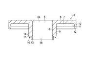
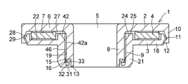
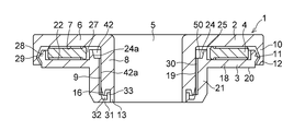
- FIG. 1 is a cross-sectional explanatory view of an example of a preferred embodiment of the present invention.
- FIG. 2 is a cross-sectional explanatory view of the upper case in the example of FIG.
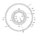
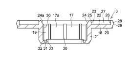
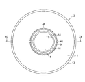
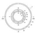
- FIG. 3 is an explanatory plan view of the lower case in the example of FIG. 4 is a cross-sectional explanatory view taken along the line IV-IV shown in FIG. 3 of the lower case of the example of FIG.
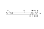
- FIG. 5 is an explanatory plan view of the thrust slide bearing piece in the example of FIG. 6 is a cross-sectional explanatory view taken along line VI-VI in FIG. 5 of the thrust slide bearing piece of the example of FIG.
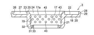
- FIG. 7 is a cross-sectional explanatory view of another example of the lower case in the example of FIG. FIG.
- FIG. 8 is a cross-sectional explanatory view of another example of the lower case in the example of FIG.
- FIG. 9 is a cross-sectional explanatory view of another example of the lower case in the example of FIG.
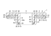
- FIG. 10 is a cross-sectional explanatory view of another example of the preferred embodiment of the present invention.
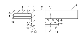
- FIG. 11 is an explanatory bottom view of the upper case in the example of FIG. 12 is a partial cross-sectional explanatory view taken along the line XII-XII shown in FIG. 11 of the upper case in the example of FIG.
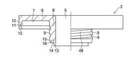
- FIG. 13 is a partial cross-sectional explanatory view of another example of the upper case according to the preferred embodiment of the present invention.
- FIG. 13 is a partial cross-
- FIG. 14 is a partial cross-sectional explanatory view of still another example of the upper case according to the preferred embodiment of the present invention.
- FIG. 15 is a partial cross-sectional explanatory view of still another example of the upper case according to the preferred embodiment of the present invention.
- FIG. 16 is a cross-sectional explanatory view of another example of the preferred embodiment of the present invention.
- FIG. 17 is an explanatory plan view of the lower case in the example of FIG. 18 is a cross-sectional explanatory view taken along the line XVIII-XVIII shown in FIG. 17 of the lower case of the example of FIG.
- FIG. 19 is a cross-sectional explanatory view of another example of the preferred embodiment of the present invention.
- FIG. 19 is a cross-sectional explanatory view of another example of the preferred embodiment of the present invention.
- FIG. 20 is an explanatory plan view of the lower case in the example of FIG. 21 is a cross-sectional explanatory view taken along the line XXI-XXI shown in FIG. 20 of the lower case of the example of FIG.
- FIG. 22 is a cross-sectional explanatory view of a main part of another example of the sealing part according to the preferred embodiment of the present invention.
- FIG. 23 is an explanatory plan view of another preferred example of the thrust slide bearing piece according to the preferred embodiment of the present invention.
- 24 is a cross-sectional explanatory view taken along the line XXIV-XXIV of the thrust slide bearing piece of the example of FIG.
- the slide bearing 1 of this example is made of a synthetic resin upper case 2, a synthetic resin lower case 3, and a synthetic resin made between the upper case 2 and the lower case 3. And a thrust sliding bearing piece 4.
- the upper case 2 has an upper disk-shaped part 6 having a circular hole 5 in the center part, an inner peripheral surface 5b having the same diameter as the inner peripheral surface 5a of the upper disk-shaped part 6 defining the circular hole 5, and an upper disk-shaped part.
- a cylindrical portion 8 formed integrally with the annular lower surface 7 of the portion 6, and a predetermined distance radially outward from the outer peripheral surface 9 of the cylindrical portion 8, integrally with the outer peripheral edge of the annular lower surface 7.
- a cylindrical engagement hanging portion 10 formed at the end, an annular engagement portion 12 formed at an end portion of the inner peripheral surface 11 of the cylindrical engagement hanging portion 10, and a cylindrical portion from the lower end portion on the inner circumferential side of the cylindrical portion 8.
- annular hanging portion 13 that hangs down in the axial direction with an inner circumferential surface that is flush with the inner circumferential surface 5 b of the portion 8 and a lower annular recess 14 in cooperation with the annular hanging portion 13.
- Annular droop that hangs downward in the axial direction from the lower end portion on the side and has a tapered surface 15 on the outer surface and tapers downward in the axial direction. It has a part 16.
- the lower case 3 has a lower disc-shaped portion 18 having an insertion hole 17 at the center, and an inner peripheral surface 19 having the same diameter as the inner peripheral surface 17a of the lower disc-shaped portion 18 that defines the insertion hole 17.
- a cylindrical portion 21 formed integrally with the annular lower surface 20 of the side disk-shaped portion 18 and a cylindrical outer peripheral surface 23 and a cylinder formed integrally with the annular upper surface 22 of the lower disk-shaped portion 18.
- the outer peripheral surface 23 of the ring-shaped upper surface 22 is separated from the outer peripheral surface 23 by a predetermined distance and is formed integrally with the outer peripheral edge of the annular upper surface 22 so as to be concentric with the annular protrusion 25 and the outer periphery of the cylindrical inner peripheral surface 26.
- annulus that forms a wide annular recess 27 in cooperation with the surface 23 and the annular upper surface 22 The mating projection 28, the annular engagement portion 29 formed at the lower end of the outer peripheral surface of the annular engagement projection 28, and the inner peripheral surface 19 of the cylindrical portion 21 are spaced apart from each other in the circumferential direction and axially And a lower end disk integrally formed at the lower end of the inner peripheral surface 19 of the cylindrical portion 21 and extending radially inward from the lower end. Is formed integrally with the inner peripheral edge of the lower end disk-shaped part 31 and cooperates with the inner peripheral surface 19 to form the lower end annular recess 32 so as to be pivoted from the inner peripheral edge of the lower end disk-shaped part 31. And a lower end annular projection 33 projecting upward in the direction.
- the thrust slide bearing piece 4 disposed in the annular recess 27 defined by the outer peripheral surface 23, the inner peripheral surface 26 and the annular upper surface 22 is an inner peripheral surface 34 having a diameter larger than the diameter of the outer peripheral surface 23. It comprises a disc 37 having a prescribed circular hole 35 in the center and an outer peripheral surface 36 having a diameter smaller than the diameter of the inner peripheral surface 26, and serves as an annular upper and lower thrust sliding bearing surface.
- the thrust slide bearing piece 4 is disposed in the annular recess 27 while holding an annular gap between the inner peripheral surface 34 and the outer peripheral surface 23 and between the outer peripheral surface 36 and the inner peripheral surface 26 and the upper surface. 38 is protruded from the opening of the annular recess 27 and slidably contacted with the annular lower surface 7, and the lower surface 39 is slidably contacted with the annular upper surface 22 defining the bottom surface of the annular recess 27 and the upper case 2 and the lower case 3. Arranged in between.
- the outer peripheral surface 9 is brought into sliding contact with the inner peripheral surface 19, the engaging portion 12 is elastically attached to the engaging portion 29, and the annular hanging portion 16 is disposed in the lower end annular recess 32, while the lower end annular recess 14.
- the lower end annular protrusion 33 is disposed on the outer peripheral surface 9 to form a sealing portion that is composed of the annular hanging portion 16 and the lower end annular recess 32, the lower end annular recess 14 and the lower end annular protrusion 33 and performs a labyrinth action.
- a sliding gap 42 a between a pair of radial sliding bearing surfaces that are in sliding contact with the inner peripheral surface 19 is sealed by the sealing portion and combined with the lower case 3.
- the annular space 42 defined by the outer peripheral surface 9 and the tapered surface 24a is communicated with the sliding gap 42a and the plurality of concave grooves 30, and the upper case 2 and the lower case 3 are connected to each other.
- the annular space 42 and the concave groove 30 that opens at the sliding gap 42a and communicates with the annular space 42 are filled with a lubricant such as grease, and the outer peripheral surface 9 and the inner peripheral surface. Lubricating oil supplied from the recessed groove 30 and the annular space 42 is always present between the radial sliding bearing surfaces with respect to 19.
- the frictional resistance is reduced by friction between synthetic resins on the radial slide bearing surface, and a plurality of concave grooves 30 serving as a reservoir for a lubricant formed on the radial slide bearing surface.
- the wide annular recess 27 of the lower case 3 is used.
- the lubricating oil reservoir is composed of a plurality of concave grooves 30 formed in the inner peripheral surface 19 so as to extend in the axial direction, but instead of or together with this, the lubricating oil reservoir
- the lubricating oil reservoir may be composed of a plurality of depressions 43 formed in a zigzag pattern on the inner peripheral surface 19, and as shown in FIG.
- the spiral groove 44 may be formed so as to surround the core O.
- the inner circumferential surface 19 is formed so as to be separated from each other in the axial direction and arranged along the axial direction.
- a plurality of annular grooves 45 may be formed.
- the lubricating oil reservoir comprising a plurality of concave grooves 30 is formed on the inner peripheral surface 19, but instead of or together with this, for example, as shown in FIGS.
- a pool portion composed of a plurality of concave grooves 46 may be formed on the outer peripheral surface 9, and the plurality of concave grooves 46 filled with a lubricant are also circumferentially oriented, like the plurality of concave grooves 30.
- a lubricating oil reservoir comprising a plurality of recesses 43, spiral grooves 44 or a plurality of annular grooves 45 is formed on the inner peripheral surface 19 in the above-described example. As shown in FIGS.
- a plurality of recesses 47, a spiral groove 48, or a plurality of annular grooves 49 are formed instead of or together with the plurality of grooves 46.
- a lubricating oil reservoir may be formed on the outer peripheral surface 9, and a plurality of depressions 47 may be formed.
- the spiral grooves 48 are arranged in a staggered manner, and the spiral groove 48 surrounds the axis O similarly to the spiral groove 44, and the plurality of annular grooves 49 includes a plurality of annular grooves 49. Similar to the grooves 45, they are spaced apart from each other in the axial direction and arranged along the axial direction.
- the annular protrusion 25 has the inner peripheral surface 24 formed of the tapered surface 24 a connected to the inner peripheral surface 19 of the cylindrical portion 21, and the annular space 42 has the tapered surface 24 a and the outer periphery.
- the annular protrusion 25 instead of this, as shown in FIGS. 16 to 18, has an annular upper surface on the inner circumferential side of the annular upper surface 22 of the lower disk-shaped portion 18.
- An annular space 42 having an inner peripheral surface 24 composed of a tapered surface 24a connected to the inner peripheral surface 19 through 50 and communicating with the plurality of concave grooves 30 and the sliding gap 42a is formed between the tapered surface 24a and an annular shape.
- the lubricating oil agent such as grease
- the slide bearing 1 provided with such an annular space 42, instead of or together with the plurality of concave grooves 46, a plurality of depressions 47, spiral grooves 48 or spiral grooves 48 as shown in FIGS.
- An annular groove 49 may be provided.
- the annular protrusion 25 is formed continuously in the circumferential direction. However, as shown in FIGS. 19 to 21, the annular protrusion 25 has an annular cavity 42 and an annular recess.
- a plurality of notched grooves 51 that communicate with the location 27 and are spaced apart from each other in the circumferential direction corresponding to the recessed grooves 30 may be formed.
- the lubricant is filled.
- the notched groove 51 and the groove 30 are filled with the lubricant in addition to the annular cavity 42, the lubricant is filled. Since such lubricating oil is supplied to the radial sliding bearing surface, the lubricating oil is always present on the radial sliding bearing surface.
- the recess 43, the spiral groove 44, and the spiral groove 44 shown in FIGS. 7, 8, and 9 may be used instead of or together with the plurality of grooves 30.
- At least one of the annular grooves 45 may be provided as a lubricating oil reservoir.
- the sliding bearing 1 shown in FIGS. 10 to 12, the sliding bearing 1 shown in FIGS. 13 to 15, and A notched groove 51 may be provided in the plain bearing 1 shown in FIGS.
- the annular hanging portion 13 is suspended from the lower end portion on the inner peripheral side of the cylindrical portion 8, and the lower end annular recess 14 is formed in cooperation with the annular hanging portion 13.
- 16 is suspended from the lower end portion on the outer peripheral side of the cylindrical portion 8, the annular hanging portion 16 is arranged in the lower end annular recess portion 32, and the lower end annular projection 32 is formed in cooperation with the inner peripheral surface 19.
- the portion 33 is projected from the inner peripheral edge of the lower end disk-shaped portion 31, and the lower end annular projection 33 is arranged in the lower end annular recess 14 to form a sealing portion that performs a labyrinth action.
- the upper case 2 is formed by omitting the annular hanging portion 13, and the lower annular hanging portion is formed. 53 may be disposed in the lower annular recess 32 of the lower case 3 to form a sealing portion that performs a labyrinth action.
- the thrust sliding bearing piece 4 made of synthetic resin shown in FIG. 23 and FIG. 24 in which the inner annular concave groove 54 and the outer annular concave groove 55 are filled with a lubricant such as grease. 5 and FIG. 6 may be used for the sliding bearing 1 instead of the synthetic resin thrust sliding bearing piece 4. In the sliding bearing 1 having the thrust sliding bearing piece 4 shown in FIGS.
- the inner annular concave groove 54 and the outer annular concave groove 55 formed on the upper surface 38 and the lower surface 39 are arranged in the circumferential direction around the axis between the upper surface 38 and the lower surface 39 and the annular lower surface 7 and the annular upper surface 22.
- the contact area between the upper surface 38 and the annular lower surface 7 which is a thrust sliding bearing surface and the annular lower surface 7 and the contact area between the lower surface 39 and the annular upper surface 22 are reduced, and the inner annular concave groove 54 and the outer circle are reduced.
- a thrust load is borne by the lubricant filled in the annular groove 55, thus reducing the frictional resistance due to friction between synthetic resins, and filling the inner annular groove 54 and the outer annular groove 55. Combined with the reduction in frictional resistance due to the lubricant, further reduction in frictional resistance can be achieved.
Landscapes
- Engineering & Computer Science (AREA)
- General Engineering & Computer Science (AREA)
- Mechanical Engineering (AREA)
- Sliding-Contact Bearings (AREA)
- Sealing Of Bearings (AREA)
- Fluid-Damping Devices (AREA)
Abstract
滑り軸受(1)は、合成樹脂製の上部ケース(2)と、合成樹脂製の下部ケース(3)と、上部ケース(2)及び下部ケース(3)間に配されている合成樹脂製のスラスト滑り軸受片(4)とを具備しており、滑り隙間(42a)及び複数個の凹溝(30)に連通すると共に外周面(9)とテーパ面(24a)とで規定された環状空所(42)が上部ケース(2)と下部ケース(3)との間に形成され、環状空所(42)と、滑り隙間(42a)で開口すると共に環状空所(42)に連通する凹溝(30)とには、グリース等の潤滑油剤が充填されおり、外周面(9)と内周面(19)とのラジアル滑り軸受面間には、常時、凹溝(30)及び環状空所(42)から供給される潤滑油剤が介在している。
Description
本発明は、特に四輪自動車におけるストラット型サスペンションの滑り軸受として組み込まれて好適な合成樹脂製の滑り軸受に関する。
主として四輪自動車の前輪に用いられ、主軸と一体となった外筒の中に油圧式ショックアブソーバを内蔵したストラットアッセンブリにコイルばねを組合せた構造のストラット型サスペンションには、一般に、ストラットの軸線に対してコイルばねの軸線を積極的にオフセットさせる構造と、ストラットの軸線に対してコイルばねの軸線を同一軸線上に配置させる構造とがあり、いずれの構造のサスペンションにおいても、車体荷重(スラスト荷重)を支持すると同時に、ステアリング操作によるストラットアッセンブリとコイルばねとの回転を円滑に許容する軸受が車体の取付部材とコイルばねの上部ばね座シートとの間に配置されている。
斯かる軸受には、サスペンション構造に起因するラジアル荷重、すなわち前者の構造においては、コイルばねの軸線がストラットの軸線に対してオフセットされているため、静止状態においてもコイルばねのストラットの軸線方向への復元力によって生じるラジアル荷重を、また後者の構造においては、ストラットの軸線とコイルばねの軸線とを同一軸線上に配置するという製作上の困難性に起因するミスアライメントによって生じるラジアル荷重を、支持する性能が要求され、上述した性能を満足する合成樹脂製の滑り軸受が例えば特許文献1において提案されている。
しかしながら、合成樹脂製の滑り軸受には、滑りを用いるために、ころがり軸受に比べて摩擦係数が高い上に、滑り面への塵埃等異物の混入でステアリング操作を重くするという問題がある。
本発明は、前記諸点に鑑みてなされたものであり、その目的とするところは、ラジアル荷重に対してより低摩擦性化を図り得て、ステアリング操作を更に軽くできる合成樹脂製の滑り軸受を提供することにある。
本発明の合成樹脂製の滑り軸受は、中央部に円孔を有する上側円盤状部、円孔を規定する上側円盤状部の内周面と同径の内周面を有すると共に上側円盤状部の円環状下面に一体的に形成された第一の円筒部、この第一の円筒部の外周面に対して径方向外方に所定の間隔をもって離れて円環状下面の外周縁に一体的に形成された円筒係合垂下部、この円筒係合垂下部の内周面の端部に一体的に形成された環状の係合部を備えた合成樹脂製の上部ケースと、中央部に挿通孔を有する下側円盤状部、挿通孔を規定する下側円盤状部の内周面と同径の内周面を有すると共に下側円盤状部の円環状下面に一体的に形成された第二の円筒部、下側円盤状部の円環状上面に一体的に形成された環状突部、この環状突部の外周面に対して径方向外方に所定の間隔をもって離れて円環状上面の外周縁に一体的に形成された環状係合突部、この環状係合突部の外周面に一体的に形成された環状の係合部を備えた合成樹脂製の下部ケースと、環状突部の外周面、環状係合突部の内周面及び下側円盤状部の円環状上面で規定された環状凹所に配されていると共に上側円盤状部及び下側円盤状部に摺接する円環状の上側及び下側のスラスト滑り軸受面を有する合成樹脂製のスラスト滑り軸受片とを具備しており、円筒係合垂下部の係合部が環状係合突部の係合部に弾性装着されて上部ケースが下部ケースに組合み合わされており、第一の円筒部の外周面と第二の円筒部の内周面との互いに摺接する一対のラジアル滑り軸受面間の滑り隙間に連通すると共に第一の円筒部の外周面と環状突部の内周面とで規定された環状空所が上部ケースと下部ケースとの間に形成されており、環状空所には潤滑油剤が充填されている。
本発明の滑り軸受によれば、ラジアル荷重に対しては、第一の円筒部の外周面と第二の円筒部の内周面との互いに摺接する一対のラジアル滑り軸受面における合成樹脂同士の摩擦による低摩擦抵抗化と、第一の円筒部の外周面と第二の円筒部の内周面との互いに摺接する一対のラジアル滑り軸受面間の滑り隙間への環状空所に充填された潤滑油剤の供給による一対のラジアル滑り軸受面における低摩擦抵抗化とが相俟って一層の低摩擦抵抗化を図ることができ、またスラスト荷重に対しては、上側円盤状部及び下側円盤状部と上側及び下側のスラスト滑り軸受面との合成樹脂同士の摩擦による低摩擦抵抗化によって、ステアリング操作を軽くすることができ、しかも、一対のラジアル滑り軸受面の摺動時のスティックスリップを抑止でき、スティックスリップに起因する異常摩擦音の発生もなくし得る。
本発明の滑り軸受において、環状突部の内周面は、第二の円筒部の内周面に連接するテーパ面を有していてもよく、この場合、環状空所は、このテーパ面と第一の円筒部の外周面とで規定されていてもよく、また、環状突部の内周面は、下側円盤状部の内周側の円環状上面を介して第二の円筒部の内周面に連接したテーパ面を有していてもよく、この場合には、環状空所は、このテーパ面と、下側円盤状部の内周側の円環状上面と、第一の円筒部の外周面とで規定されていてもよい。
本発明の滑り軸受において、滑り隙間を形成する一対のラジアル滑り軸受面のうちの少なくとも一方には、滑り隙間で開口する潤滑油剤の溜り部が形成されていてもよく、斯かる溜り部が形成されていると、一対のラジアル滑り軸受面間の滑り隙間への環状空所に充填された潤滑油剤の供給を促進できて、一対のラジアル滑り軸受面における低摩擦抵抗化をより確保でき、斯かる溜り部には、潤滑油剤が充填されていてもよく、また、溜り部は、ラジアル滑り軸受面を形成する第一の円筒部の外周面及び第二の円筒部の内周面のうちの少なくとも一方に円周方向に互いに離間していると共に軸方向に伸びた複数個の凹溝、ラジアル滑り軸受面を形成する第一の円筒部の外周面及び第二の円筒部の内周面のうちの少なくとも一方に形成された複数個の窪み、ラジアル滑り軸受面を形成する第一の円筒部の外周面及び第二の円筒部の内周面のうちの少なくとも一方に形成された螺旋凹溝及びラジアル滑り軸受面を形成する第一の円筒部の外周面及び第二の円筒部の内周面のうちの少なくとも一方に形成された軸方向に沿って配列された複数個の環状溝のうちの少なくとも一つを有していてもよい。
本発明の滑り軸受において、環状突部には、環状空所及び環状凹所に連通すると共に円周方向に互いに離間した複数個の切欠き凹溝が形成されていてもよく、斯かる切欠き凹溝には、潤滑油剤が充填されていてもよい。
斯かる切欠き凹溝に潤滑油剤が充填されていると、環状空所に切欠き凹溝から潤滑油剤を補給でき、低摩擦抵抗化をより長期に亘って維持できる。
本発明の滑り軸受において、好ましい例では、上部ケースは、第一の円筒部の内周側の下端部から軸方向下方に垂下する第一の環状垂下部及びこの第一の環状垂下部と協働して第一の下端環状凹部を形成するように第一の円筒部の外周側の下端部から軸方向下方に垂下すると共に外面にテーパ面を有して軸方向下方に向かって先細りとなる第二の環状垂下部を備えており、下部ケースは、第二の円筒部の内周面の下端から径方向内方に伸びた下端円盤状部、第二の円筒部の内周面と協働して第二の下端環状凹部を形成するように下端円盤状部から軸方向上方に突出した下端環状突部を備えており、ラビリンス作用をなす密封部を形成するように、第二の環状垂下部が第二の下端環状凹部に配されていると共に下端環状突部が第一の下端環状凹部に配されており、他の好ましい例では、上部ケースは、第一の円筒部の下端部から第一の円筒部の外周面と面一の外周面をもって軸方向下方に垂下する下端環状垂下部を備えており、下部ケースは、第二の円筒部の内周面の下端から径方向内方に伸びた下端円盤状部、第二の円筒部の内周面と協働して下端環状凹部を形成するように下端円盤状部から軸方向上方に突出した下端環状突部を備えており、ラビリンス作用をなす密封部を形成するように、下端環状突部が下端環状凹部に配されている。
斯かる例の本発明の滑り軸受によれば、上部ケースと下部ケースとの下端部にラビリンス構造による密封部が形成されるので、上部ケースの円筒部と下部ケースの円筒部で形成されるラジアル滑り軸受面への塵埃等の異物の侵入を極力防止することができる。
本発明の滑り軸受において、上部ケース及び下部ケースは合成樹脂製であり、上部ケース及び下部ケースのうちの少なくとも一方を形成する合成樹脂は、ポリアセタール樹脂、ポリアミド樹脂、ポリエステル樹脂などの熱可塑性合成樹脂であってもよく、また、スラスト滑り軸受片を形成する合成樹脂は、ポリアセタール樹脂、ポリアミド樹脂、ポリオレフィン樹脂、ポリエステル樹脂などの熱可塑性合成樹脂であってもよい。
本発明の滑り軸受において、潤滑油剤は、シリコーングリース、カルシウム石鹸基グリース、カルシウム複合石鹸基グリース、リチウム石鹸基グリース等を含み、特に、基油がシリコーン油であって、25℃における動粘度が100cSt以上500000cSt以下であり、これに増ちょう剤を含有して混合ちょう度を200以上400以下としたシリコーングリースを本発明の潤滑油剤の好ましい例として挙げることができる。
本発明では、上部ケースと下部ケースと上部ケース及び下部ケース間に配されるスラスト滑り軸受片との間のスラスト滑り軸受面に上述のグリース等の潤滑油剤を介在させてもよく、斯かる潤滑油剤の潤滑効果による低摩擦性に加えて、摺動時におけるスティックスリップを抑止でき、当該スティックスリップの発生に起因する異常摩擦音の発生もなくし得る。
本発明によれば、ラジアル荷重に対してより低摩擦性化を図り得て、ステアリング操作を更に軽くできる合成樹脂製の滑り軸受を提供できる。
次に本発明を、図に示す好ましい実施の形態の例に基づいて詳細に説明する。なお、本発明はこれらの例に何等限定されないのである。
図1から図6において、本例の滑り軸受1は、合成樹脂製の上部ケース2と、合成樹脂製の下部ケース3と、上部ケース2及び下部ケース3間に配されている合成樹脂製のスラスト滑り軸受片4とを具備している。
上部ケース2は、中央部に円孔5を有する上側円盤状部6と、円孔5を規定する上側円盤状部6の内周面5aと同径の内周面5bを有すると共に上側円盤状部6の円環状下面7に一体的に形成された円筒部8と、円筒部8の外周面9に対して径方向外方に所定の間隔をもって離れて円環状下面7の外周縁に一体的に形成された円筒係合垂下部10と、円筒係合垂下部10の内周面11の端部に形成された環状の係合部12と、円筒部8の内周側の下端部から円筒部8の内周面5bと面一の内周面をもって軸方向下方に垂下する環状垂下部13と、環状垂下部13と協働して下端環状凹部14を形成するように円筒部8の外周側の下端部から軸方向下方に垂下すると共に外面にテーパ面15を有して軸方向下方に向かって先細りとなる環状垂下部16を備えている。
下部ケース3は、中央部に挿通孔17を有する下側円盤状部18と、挿通孔17を規定する下側円盤状部18の内周面17aと同径の内周面19を有すると共に下側円盤状部18の円環状下面20に一体的に形成された円筒部21と、下側円盤状部18の円環状上面22に一体的に形成されていると共に円筒状の外周面23及び円筒部21の内周面19に連接する截頭円錐面、即ち、テーパ面24aからなる内周面24を有し、且つ、上方に向かって先細りとなった環状突部25と、環状突部25の外周面23に対して径方向外方に所定の間隔をもって離れて円環状上面22の外周縁に環状突部25と同心に一体的に形成されていると共に円筒状の内周面26で外周面23及び円環状上面22と協働して幅広の環状凹所27を形成する環状係合突部28と、環状係合突部28の外周面の下端に形成された環状の係合部29と、円筒部21の内周面19に円周方向に互いに離間していると共に軸方向に伸びて形成された複数個の凹溝30からなる潤滑油剤の溜り部と、円筒部21の内周面19の下端に当該下端から径方向内方に伸びて一体的に形成された下端円盤状部31と、下端円盤状部31の内周縁に一体的に形成されていると共に内周面19と協働して下端環状凹部32を形成するように下端円盤状部31の内周縁から軸方向上方に突出した下端環状突部33とを備えている。
外周面23、内周面26及び円環状上面22で規定された環状凹所27に配されているスラスト滑り軸受片4は、外周面23の径よりも大きい径をもった内周面34で規定された円孔35を中央部に有すると共に内周面26の径よりも小さい径をもった外周面36を有する円板37からなり、円環状の上側及び下側のスラスト滑り軸受面としての上面38及び下面39と、上面38及び下面39に円孔35を囲んで形成された環状溝40と、一端で環状溝40に連通する一方、他端が外周面36で開口すると共に円周方向に等間隔に配されて上面38及び下面39に形成された複数個の放射状溝41とを有している。
スラスト滑り軸受片4は、内周面34と外周面23との間及び外周面36と内周面26との間の夫々に環状隙間を保持して環状凹所27に配されていると共に上面38を環状凹所27の開口部より突出させて円環状下面7に摺接させ、下面39を環状凹所27の底面を規定する円環状上面22に摺接させて上部ケース2及び下部ケース3間に配されている。
上部ケース2は、外周面9を内周面19に摺接させ、係合部12を係合部29に弾性装着させると共に環状垂下部16を下端環状凹部32に配する一方、下端環状凹部14に下端環状突部33を配させて、環状垂下部16及び下端環状凹部32と下端環状凹部14及び下端環状突部33とからなると共にラビリンス作用をなす密封部を形成して、外周面9と内周面19との互いに摺接する一対のラジアル滑り軸受面間の滑り隙間42aをこの密封部により密閉して下部ケース3に組み合わされている。
このように組み合わされた滑り軸受1において、滑り隙間42a及び複数個の凹溝30に連通すると共に外周面9とテーパ面24aとで規定された環状空所42が上部ケース2と下部ケース3との間に形成され、環状空所42と、滑り隙間42aで開口すると共に環状空所42に連通する凹溝30とには、グリース等の潤滑油剤が充填されおり、外周面9と内周面19とのラジアル滑り軸受面間には、常時、凹溝30及び環状空所42から供給される潤滑油剤が介在している。
滑り軸受1では、ラジアル荷重に対してはラジアル滑り軸受面における合成樹脂同士の摩擦による低摩擦抵抗化と、ラジアル滑り軸受面に形成された潤滑油剤の溜り部としての複数個の凹溝30及び環状空所42から供給される潤滑油剤による低摩擦抵抗化とが相俟って一層の低摩擦抵抗化を図ることができ、スラスト荷重に対しては下部ケース3の幅広の環状凹所27での円環状上面22とスラスト滑り軸受片4の円環状の下面39との間のスラスト滑り軸受面又はスラスト滑り軸受片4の円環状の上面38と上部ケース2の上側円盤状部6の円環状下面7とのスラスト滑り軸受面の合成樹脂同士の摩擦による低摩擦抵抗化と、スラスト滑り軸受面への潤滑油剤の介在による低摩擦抵抗化とが相俟って一層の低摩擦抵抗化を図ることができ、ラジアル荷重及びスラスト荷重下での上部ケース2に対する下部ケース3の軸心Oの周りでの円周方向、即ち、R方向の相対回転を円滑に許容することができる。
上記の例では、潤滑油剤の溜り部は、内周面19に軸方向に伸びて形成された複数個の凹溝30からなっているが、これに代えて又はこれと共に、潤滑油剤の溜り部は、例えば、図7に示すように、内周面19に千鳥状に配列されて形成された複数個の窪み43からなっていてもよく、図8に示すように、内周面19に軸心Oを取り囲んで形成された螺旋溝44からなっていてもよく、更には、図9に示すように、内周面19に軸方向に互いに離間して且つ軸方向に沿って配列されて形成された複数個の環状溝45からなっていてもよい。更に、上記の例では、複数個の凹溝30からなる潤滑油剤の溜り部を内周面19に形成したが、これに代えて又はこれと共に、例えば、図10から図12に示すように、複数個の凹溝46からなる溜り部を外周面9に形成してもよく、潤滑剤が充填される斯かる複数個の凹溝46も、複数個の凹溝30と同様に、円周方向に互いに離間していると共に軸方向に伸びており、更に、上記の例では、複数個の窪み43、螺旋溝44又は複数個の環状溝45からなる潤滑油剤の溜り部を内周面19に形成したが、これらに代えて又はこれらと共に、複数個の凹溝46と同様に、図13から図15の夫々に示すように、複数個の窪み47、螺旋溝48又は複数個の環状溝49からなる潤滑油剤の溜り部を外周面9に形成してもよく、複数個の窪み47は、複数個の窪み43と同様に、千鳥状に配列されており、螺旋溝48は、螺旋溝44と同様に、軸心Oを取り囲んでおり、複数個の環状溝49は、複数個の環状溝45と同様に、軸方向に互いに離間して且つ軸方向に沿って配列されている。
また、上記の例では、環状突部25は、円筒部21の内周面19に連接するテーパ面24aからなる内周面24を有しており、環状空所42は、テーパ面24aと外周面9とで規定されているが、これに代えて、図16から図18に示すように、環状突部25が、下側円盤状部18の円環状上面22において内周側の円環状上面50を介して内周面19に連接するテーパ面24aからなる内周面24を有し、複数個の凹溝30及び滑り隙間42aに連通する環状空所42が、テーパ面24aと、円環状上面50と、外周面9とで規定されていてもよく、斯かる環状空所42にも、前記の例と同様に、グリース等の潤滑油剤が充填される。斯かる環状空所42を具備した滑り軸受1においても、複数個の凹溝46に代えて又はこれと共に、図13、図14及び図15に示すような複数個の窪み47、螺旋溝48又は環状溝49を設けてもよい。更に、上記の滑り軸受1では、環状突部25は、円周方向に連続に形成されているが、図19から図21に示すように、環状突部25に、環状空所42及び環状凹所27に連通すると共に凹溝30に対応して円周方向に互いに離間して配された複数個の切欠き凹溝51が形成されていてもよく、これら切欠き凹溝51には、環状空所42及び凹溝30と同様に、潤滑油剤が充填されており、このように環状空所42に加えて、切欠き凹溝51及び凹溝30に潤滑油剤が充填されていると、斯かる潤滑油剤がラジアル滑り軸受面に供給されるので、ラジアル滑り軸受面には常時、潤滑油剤が介在することになる。
切欠き凹溝51を具備した滑り軸受1においても、複数個の凹溝30に代えて又は複数個の凹溝30と共に、図7、図8及び図9に示した窪み43、螺旋溝44及び環状溝45の少なくとも一つを潤滑油剤の溜り部として具備していてもよく、更には、図10から図12に示される滑り軸受1、図13から図15の夫々に示される滑り軸受1及び図16から図18に示される滑り軸受1に、切欠き凹溝51を設けてもよい。
また、上記の滑り軸受1では、環状垂下部13を円筒部8の内周側の下端部から垂下させ、環状垂下部13と協働して下端環状凹部14を形成するように、環状垂下部16を円筒部8の外周側の下端部から垂下させ、環状垂下部16を下端環状凹部32に配し、内周面19と協働して下端環状凹部32を形成するように、下端環状突部33を下端円盤状部31の内周縁から突出させ、下端環状突部33を下端環状凹部14に配して、ラビリンス作用をなす密封部を形成したが、図22に示すように、円筒部8の下端部に円筒部8の外周面9と面一であって、外周面9に連接する外周面52をもって円筒部8の下端部から軸方向下方に垂下する下環状垂下部53を備えている一方、環状垂下部13を省いて上部ケース2を形成し、下環状垂下部53を下部ケース3の下端環状凹部32に配置してラビリンス作用をなす密封部を形成してもよく、斯かる密封部によっても、上部ケース2の円筒部8の外周面9と下部ケース3の円筒部21の内周面19で形成されるラジアル滑り軸受面への塵埃等の異物の侵入を極力防止することができる。
更に、合成樹脂製のスラスト滑り軸受片4の上面38及び下面39に円周方向に伸びると共に径方向において内側及び外側に互いに同心に形成された内側円環状凹溝54及び外側円環状凹溝55を具備し、これら内側円環状凹溝54及び外側円環状凹溝55の夫々にグリース等の潤滑油剤が充填されている図23及び図24に示す合成樹脂製のスラスト滑り軸受片4を、図5及び図6に示す合成樹脂製のスラスト滑り軸受片4に代えて、滑り軸受1に用いてもよく、このように図23及び図24に示すスラスト滑り軸受片4を有する滑り軸受1では、上面38及び下面39に形成された内側円環状凹溝54及び外側円環状凹溝55により、上面38及び下面39と円環状下面7及び円環状上面22との軸心回りでの円周方向の相対回転において、スラスト滑り軸受面であって摺動面となる上面38と円環状下面7との接触面積及び下面39と円環状上面22との接触面積を減少させると共に内側円環状凹溝54及び外側円環状凹溝55に充填された潤滑油剤でスラスト荷重を負担させ、而して、合成樹脂同士の摩擦による低摩擦抵抗化と、内側円環状凹溝54及び外側円環状凹溝55に充填された潤滑油剤による低摩擦抵抗化とが相俟って一層の低摩擦抵抗化を図ることができる。
1 滑り軸受
2 上部ケース
3 下部ケース
4 スラスト滑り軸受片
5 円孔
6 上側円盤状部
7 円環状下面
8 円筒部
10 円筒係合垂下部
12 係合部
17 挿通孔
18 下側円盤状部
19 内周面
20 円環状下面
21 円筒部
22 円環状上面
25 環状突部
27 環状凹所
28 環状係合突部
29 係合部
30、46 凹溝
40、45、49 環状溝
42 環状空所
42a 滑り隙間
43、47 窪み
44、48 螺旋溝
50 円環状上面
51 切欠き凹溝
2 上部ケース
3 下部ケース
4 スラスト滑り軸受片
5 円孔
6 上側円盤状部
7 円環状下面
8 円筒部
10 円筒係合垂下部
12 係合部
17 挿通孔
18 下側円盤状部
19 内周面
20 円環状下面
21 円筒部
22 円環状上面
25 環状突部
27 環状凹所
28 環状係合突部
29 係合部
30、46 凹溝
40、45、49 環状溝
42 環状空所
42a 滑り隙間
43、47 窪み
44、48 螺旋溝
50 円環状上面
51 切欠き凹溝
Claims (11)
- 中央部に円孔を有する上側円盤状部、円孔を規定する上側円盤状部の内周面と同径の内周面を有すると共に上側円盤状部の円環状下面に一体的に形成された第一の円筒部、この第一の円筒部の外周面に対して径方向外方に所定の間隔をもって離れて円環状下面の外周縁に一体的に形成された円筒係合垂下部、この円筒係合垂下部の内周面の端部に一体的に形成された環状の係合部を備えた合成樹脂製の上部ケースと、中央部に挿通孔を有する下側円盤状部、挿通孔を規定する下側円盤状部の内周面と同径の内周面を有すると共に下側円盤状部の円環状下面に一体的に形成された第二の円筒部、下側円盤状部の円環状上面に一体的に形成された環状突部、この環状突部の外周面に対して径方向外方に所定の間隔をもって離れて円環状上面の外周縁に一体的に形成された環状係合突部、この環状係合突部の外周面に一体的に形成された環状の係合部を備えた合成樹脂製の下部ケースと、環状突部の外周面、環状係合突部の内周面及び下側円盤状部の円環状上面で規定された環状凹所に配されていると共に上側円盤状部及び下側円盤状部に摺接する円環状の上側及び下側のスラスト滑り軸受面を有する合成樹脂製のスラスト滑り軸受片とを具備しており、円筒係合垂下部の係合部が環状係合突部の係合部に弾性装着されて上部ケースが下部ケースに組合み合わされており、第一の円筒部の外周面と第二の円筒部の内周面との互いに摺接する一対のラジアル滑り軸受面間の滑り隙間に連通すると共に第一の円筒部の外周面と環状突部の内周面とで規定された環状空所が上部ケースと下部ケースとの間に形成されており、環状空所には潤滑油剤が充填されている滑り軸受。
- 環状突部の内周面は、第二の円筒部の内周面に連接するテーパ面を有しており、環状空所は、このテーパ面と上部ケースの第一の円筒部の外周面とで規定されている請求項1に記載の滑り軸受。
- 環状突部の内周面は、下側円盤状部の内周側の円環状上面を介して第二の円筒部の内周面に連接したテーパ面を有しており、環状空所は、このテーパ面と、下側円盤状部の内周側の円環状上面と、第一の円筒部の外周面とで規定されている請求項1に記載の滑り軸受。
- 滑り隙間を形成する一対のラジアル滑り軸受面のうちの少なくとも一方には、滑り隙間で開口する潤滑油剤の溜り部が形成されており、この溜り部には潤滑油剤が充填されている請求項1から3のいずれか一項に記載の滑り軸受。
- 溜り部は、ラジアル滑り軸受面を形成する第一の円筒部の外周面及び第二の円筒部の内周面のうちの少なくとも一方に円周方向に互いに離間していると共に軸方向に伸びた複数個の凹溝を有している請求項4に記載の滑り軸受。
- 溜り部は、ラジアル滑り軸受面を形成する第一の円筒部の外周面及び第二の円筒部の内周面のうちの少なくとも一方に形成された複数個の窪みを有している請求項4又は5に記載の滑り軸受。
- 溜り部は、ラジアル滑り軸受面を形成する第一の円筒部の外周面及び第二の円筒部の内周面のうちの少なくとも一方に形成された螺旋凹溝を有している請求項4から6のいずれか一項に記載の滑り軸受。
- 溜り部は、ラジアル滑り軸受面を形成する第一の円筒部の外周面及び第二の円筒部の内周面のうちの少なくとも一方に形成された軸方向に沿って配列された複数個の環状溝を有している請求項4から7のいずれか一項に記載の滑り軸受。
- 環状突部には、環状空所及び環状凹所に連通すると共に円周方向に互いに離間した複数個の切欠き凹溝が形成されており、この切欠き凹溝には、潤滑油剤が充填されている請求項1から8のいずれか一項に記載の滑り軸受。
- 上部ケースは、第一の円筒部の内周側の下端部から軸方向下方に垂下する第一の環状垂下部及びこの第一の環状垂下部と協働して第一の下端環状凹部を形成するように第一の円筒部の外周側の下端部から軸方向下方に垂下すると共に外面にテーパ面を有して軸方向下方に向かって先細りとなる第二の環状垂下部を備えており、下部ケースは、第二の円筒部の内周面の下端から径方向内方に伸びた下端円盤状部、第二の円筒部の内周面と協働して第二の下端環状凹部を形成するように下端円盤状部から軸方向上方に突出した下端環状突部を備えており、ラビリンス作用をなす密封部を形成するように、第二の環状垂下部が第二の下端環状凹部に配されていると共に下端環状突部が第一の下端環状凹部に配されている請求項1から9のいずれか一項に記載の滑り軸受。
- 上部ケースは、第一の円筒部の下端部から第一の円筒部の外周面と面一の外周面をもって軸方向下方に垂下する下端環状垂下部を備えており、下部ケースは、第二の円筒部の内周面の下端から径方向内方に伸びた下端円盤状部、第二の円筒部の内周面と協働して下端環状凹部を形成するように下端円盤状部から軸方向上方に突出した下端環状突部を備えており、ラビリンス作用をなす密封部を形成するように、下端環状突部が下端環状凹部に配されている請求項1から9のいずれか一項に記載の滑り軸受。
Applications Claiming Priority (2)
| Application Number | Priority Date | Filing Date | Title |
|---|---|---|---|
| JP2014-124837 | 2014-06-17 | ||
| JP2014124837A JP2016003723A (ja) | 2014-06-17 | 2014-06-17 | 滑り軸受 |
Publications (1)
| Publication Number | Publication Date |
|---|---|
| WO2015194097A1 true WO2015194097A1 (ja) | 2015-12-23 |
Family
ID=54935112
Family Applications (1)
| Application Number | Title | Priority Date | Filing Date |
|---|---|---|---|
| PCT/JP2015/002689 Ceased WO2015194097A1 (ja) | 2014-06-17 | 2015-05-27 | 滑り軸受 |
Country Status (2)
| Country | Link |
|---|---|
| JP (1) | JP2016003723A (ja) |
| WO (1) | WO2015194097A1 (ja) |
Cited By (1)
| Publication number | Priority date | Publication date | Assignee | Title |
|---|---|---|---|---|
| CN116945012A (zh) * | 2023-09-04 | 2023-10-27 | 西可装备制造(衡阳)有限公司 | 抛光设备 |
Citations (6)
| Publication number | Priority date | Publication date | Assignee | Title |
|---|---|---|---|---|
| JPH074435A (ja) * | 1993-06-16 | 1995-01-10 | Nagata Buhin Seizo Kk | 軸受部材および軸受部材の摩耗防止方法 |
| JPH0949529A (ja) * | 1995-08-08 | 1997-02-18 | Oiles Ind Co Ltd | 合成樹脂軸受 |
| JPH09296841A (ja) * | 1996-04-30 | 1997-11-18 | Kayaba Ind Co Ltd | 油圧緩衝器及びガススプリング |
| WO2011070772A1 (ja) * | 2009-12-11 | 2011-06-16 | オイレス工業株式会社 | 合成樹脂製スラスト滑り軸受 |
| JP2012036983A (ja) * | 2010-08-06 | 2012-02-23 | Oiles Corp | スラスト滑り軸受 |
| WO2013108596A1 (ja) * | 2012-01-17 | 2013-07-25 | オイレス工業株式会社 | スラスト滑り軸受 |
-
2014
- 2014-06-17 JP JP2014124837A patent/JP2016003723A/ja active Pending
-
2015
- 2015-05-27 WO PCT/JP2015/002689 patent/WO2015194097A1/ja not_active Ceased
Patent Citations (6)
| Publication number | Priority date | Publication date | Assignee | Title |
|---|---|---|---|---|
| JPH074435A (ja) * | 1993-06-16 | 1995-01-10 | Nagata Buhin Seizo Kk | 軸受部材および軸受部材の摩耗防止方法 |
| JPH0949529A (ja) * | 1995-08-08 | 1997-02-18 | Oiles Ind Co Ltd | 合成樹脂軸受 |
| JPH09296841A (ja) * | 1996-04-30 | 1997-11-18 | Kayaba Ind Co Ltd | 油圧緩衝器及びガススプリング |
| WO2011070772A1 (ja) * | 2009-12-11 | 2011-06-16 | オイレス工業株式会社 | 合成樹脂製スラスト滑り軸受 |
| JP2012036983A (ja) * | 2010-08-06 | 2012-02-23 | Oiles Corp | スラスト滑り軸受 |
| WO2013108596A1 (ja) * | 2012-01-17 | 2013-07-25 | オイレス工業株式会社 | スラスト滑り軸受 |
Cited By (2)
| Publication number | Priority date | Publication date | Assignee | Title |
|---|---|---|---|---|
| CN116945012A (zh) * | 2023-09-04 | 2023-10-27 | 西可装备制造(衡阳)有限公司 | 抛光设备 |
| CN116945012B (zh) * | 2023-09-04 | 2024-03-26 | 西可装备制造(衡阳)有限公司 | 抛光设备 |
Also Published As
| Publication number | Publication date |
|---|---|
| JP2016003723A (ja) | 2016-01-12 |
Similar Documents
| Publication | Publication Date | Title |
|---|---|---|
| EP1365162B1 (en) | Synthetic resin sliding bearing | |
| RU2583986C2 (ru) | Упорный подшипник скольжения | |
| JP5332379B2 (ja) | 合成樹脂製スラスト滑り軸受 | |
| JP5910000B2 (ja) | 合成樹脂製の滑り軸受 | |
| RU2583827C1 (ru) | Упорный подшипник скольжения и монтажная конструкция подвески стоечного типа с использованием упорного подшипника скольжения | |
| JP6057814B2 (ja) | 合成樹脂製の滑り軸受 | |
| JP2012255500A (ja) | 合成樹脂製の滑り軸受 | |
| CN103620244B (zh) | 推力滑动轴承 | |
| KR20110065525A (ko) | 스러스트 슬라이드 베어링 | |
| CA2825380A1 (en) | Synthetic resin-made thrust sliding bearing | |
| JP2014145430A (ja) | 合成樹脂製の滑り軸受 | |
| JP6017340B2 (ja) | 合成樹脂製の滑り軸受 | |
| JP5909976B2 (ja) | 合成樹脂製の滑り軸受 | |
| JP6322889B2 (ja) | 合成樹脂製の滑り軸受 | |
| US10422374B2 (en) | Synthetic resin-made sliding bearing | |
| JP2008175349A (ja) | ストラット軸受 | |
| JP3709939B2 (ja) | 合成樹脂軸受 | |
| JP2004225754A (ja) | 合成樹脂製の滑り軸受及びこの滑り軸受を用いたストラット型サスペンションの取付構造 | |
| WO2015194097A1 (ja) | 滑り軸受 | |
| CN108350946B (zh) | 合成树脂制滑动轴承 | |
| JP6211124B2 (ja) | 合成樹脂製の滑り軸受 | |
| EP3385555B1 (en) | Synthetic resin sliding bearing | |
| JP2018132191A (ja) | 合成樹脂製の滑り軸受 | |
| JP6319345B2 (ja) | 合成樹脂製の滑り軸受 | |
| RU2575550C2 (ru) | Упорный подшипник скольжения |
Legal Events
| Date | Code | Title | Description |
|---|---|---|---|
| 121 | Ep: the epo has been informed by wipo that ep was designated in this application |
Ref document number: 15809055 Country of ref document: EP Kind code of ref document: A1 |
|
| NENP | Non-entry into the national phase |
Ref country code: DE |
|
| 122 | Ep: pct application non-entry in european phase |
Ref document number: 15809055 Country of ref document: EP Kind code of ref document: A1 |