WO2015190280A1 - エアリフトポンプおよび水中堆積物の吸引方法 - Google Patents
エアリフトポンプおよび水中堆積物の吸引方法 Download PDFInfo
- Publication number
- WO2015190280A1 WO2015190280A1 PCT/JP2015/065045 JP2015065045W WO2015190280A1 WO 2015190280 A1 WO2015190280 A1 WO 2015190280A1 JP 2015065045 W JP2015065045 W JP 2015065045W WO 2015190280 A1 WO2015190280 A1 WO 2015190280A1
- Authority
- WO
- WIPO (PCT)
- Prior art keywords
- working fluid
- pipe
- main pipe
- working
- water
- Prior art date
Links
Images


Classifications
-
- E—FIXED CONSTRUCTIONS
- E02—HYDRAULIC ENGINEERING; FOUNDATIONS; SOIL SHIFTING
- E02F—DREDGING; SOIL-SHIFTING
- E02F3/00—Dredgers; Soil-shifting machines
- E02F3/04—Dredgers; Soil-shifting machines mechanically-driven
- E02F3/88—Dredgers; Soil-shifting machines mechanically-driven with arrangements acting by a sucking or forcing effect, e.g. suction dredgers
-
- F—MECHANICAL ENGINEERING; LIGHTING; HEATING; WEAPONS; BLASTING
- F04—POSITIVE - DISPLACEMENT MACHINES FOR LIQUIDS; PUMPS FOR LIQUIDS OR ELASTIC FLUIDS
- F04F—PUMPING OF FLUID BY DIRECT CONTACT OF ANOTHER FLUID OR BY USING INERTIA OF FLUID TO BE PUMPED; SIPHONS
- F04F1/00—Pumps using positively or negatively pressurised fluid medium acting directly on the liquid to be pumped
- F04F1/18—Pumps using positively or negatively pressurised fluid medium acting directly on the liquid to be pumped the fluid medium being mixed with, or generated from the liquid to be pumped
- F04F1/20—Pumps using positively or negatively pressurised fluid medium acting directly on the liquid to be pumped the fluid medium being mixed with, or generated from the liquid to be pumped specially adapted for raising liquids from great depths, e.g. in wells
Definitions
- the present invention relates to an air lift pump and a method for sucking underwater deposits.
- Patent Document 1 discloses a liquid booster that injects bubbles of a working fluid from the lower part of a riser pipe through an injection nozzle and raises the inside of the riser pipe with warm water.
- the air bubbles in the working fluid are separated from the hot water by the gas-liquid separation drum installed at the top of the riser, then condensed and liquefied by the air-cooled condenser, lowered by the dead weight in the downcomer, and again introduced into the lower part of the riser.
- it is heated by hot water in the riser tube to form boiling bubbles.
- Patent Document 2 discloses a deep bottom resource suction device in which an air lift pipe is installed in the sea and sucks seabed minerals and the like together with seawater.
- Undersea resources such as rare earths and manganese nodules are extremely important domestic resources that are essential for the stable supply of resources in Japan, and their development and use are expected.
- a pump type and a bucket type are known in addition to the air lift type, but the air lift type is promising in terms of achieving both productivity and maintainability.
- this liquid push-up device is configured to cause a phase change of the working fluid by utilizing the temperature difference between the hot water temperature in the riser pipe and the ambient temperature of the downfall pipe.
- the desired phase change does not occur in the working fluid, and it is difficult to continuously operate.
- this liquid push-up device is configured so that the working fluid is injected into the riser in the liquid phase and heated in the riser to become a gas phase, so that a phase change of the working fluid occurs. It is necessary to provide this mechanism inside the riser tube, which not only makes the configuration of the phase change portion complicated, but also may cause problems such as damage to the phase change portion due to sucked earth and sand.
- the conventional air lift type pumping system requires a power source for introducing the working fluid into the pipe, such as the pressure feed pump disclosed in Patent Document 2 above. Since the load increases as the injection depth increases, development of a pump system that realizes energy saving at low cost has been demanded.
- an object of the present invention is to provide an air lift pump and a method for sucking underwater deposits that can efficiently suck underwater deposits.
- the object of the present invention is to have a main pipe and a working pipe installed in an upright state in water, and deposit from a suction port formed in a lower portion of the main pipe by introducing a working fluid from the working pipe to the main pipe.
- An air lift pump that sucks an object together with water and conveys it upwards, wherein the working pipe guides the supplied liquid-phase working fluid downward in a state insulated from outside water, and the heat insulation This is achieved by an air lift pump including a heat exchanging unit that heats and vaporizes the working fluid that has passed through the unit by heat exchange with external water and supplies the heat to the main pipe.
- the heat exchanging portion guides the working fluid upward from the heat insulating portion toward the main pipe.
- a gas-liquid separator that recovers the gas-phase working fluid rising up the main pipe; a compressor that compresses and heats the recovered working fluid; and the working fluid from the compressor that is installed in water It is preferable to further include a heat dissipating part that exchanges heat and cools, and an expander that expands and liquefies the working fluid that has passed through the heat dissipating part, and introduces the liquid working fluid that has passed through the expander into the working pipe.
- it may further comprise a gas-liquid separator that recovers the gas-phase working fluid that rises in the main pipe, and a cooler that cools and collects the recovered working fluid. It is also possible to introduce a working fluid into the working tube.
- the object of the present invention is to install a main pipe and a working pipe in an upright state in water, and introduce a working fluid from the working pipe into the main pipe, thereby depositing from a suction port formed at a lower portion of the main pipe.
- FIG. 4 It is a schematic block diagram of the air lift pump which concerns on one Embodiment of this invention. It is a schematic block diagram of the air lift pump which concerns on other embodiment of this invention. It is a schematic block diagram of the air lift pump which concerns on one Example of this invention. It is a schematic block diagram of the air lift pump which concerns on the other Example of this invention. It is a figure which shows an example of the measurement data of the air lift pump shown in FIG. 4, (a) has shown the flow volume change of the working fluid, (b) has each shown the temperature change of the working fluid. It is a figure which shows the measurement result of the pumping characteristic of the air lift pump shown in FIG. 4, (a)-(c) compares the internal diameter of the main pipe with each other, and compares with the prior art. It is the figure which compared the measurement result shown in FIG. 6 with the numerical calculation result.
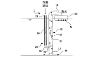
- FIG. 1 is a schematic configuration diagram of an air lift pump according to an embodiment of the present invention.
- the air lift pump 1 includes a main pipe 10 and a working pipe 20 that are installed in a standing state in water such as seawater by a support member (not shown).
- the air lift pump 1 of this embodiment has versatility that can be used in an open space.
- the main pipe 10 has a suction port 12 formed at the lower end side and a discharge port 14 formed at the upper end side, and the suction port 12 is located in the vicinity of the bottom surface such as the seabed, so that water such as seabed minerals, earth and sand, sludge, etc.
- the deposit is arranged so as to be sucked from the suction port 12.
- the discharge port 14 is located above the water surface such as the sea surface, and the underwater sediment sucked together with the water such as seawater from the suction port 12 is discharged from the discharge port 14 and collected by the collection unit 30.
- the standing state of the main pipe 10 is preferably an upright state, but may be an inclined state.
- the working tube 20 has a lower end side connection port 22 connected above the suction port 12 of the main tube 10.
- An introduction port 24 is formed on the upper end side of the working tube 20, and a liquid working fluid is introduced into the working tube 20 from the introduction port 24.
- the working tube 20 includes a heat insulating portion 26 and a heat exchanging portion 28, the heat insulating portion 26 is disposed on the introduction port 24 side, and the heat exchanging portion 28 is disposed on the connection port 22 side.
- the standing state of the working tube 20 may be not only an upright state but also an inclined state.
- the heat insulating part 26 guides the working fluid passing through the inside downward while being insulated from the external water.
- the specific structure of the heat insulation part 26 is not specifically limited, For example, the structure which coat
- the heat exchanging unit 28 heats and vaporizes the working fluid passing through the inside by heat exchange with external water and supplies the working fluid to the main pipe 10.
- the heat exchanging portion 28 can be composed of a metal tube having excellent thermal conductivity such as an aluminum alloy, for example, and may be appropriately curved in order to secure a heat transfer area necessary for vaporizing the working fluid.
- the heat insulating part 26 is configured by covering the pipe with a heat insulating material or the like, a part of the pipe can be exposed to form the heat exchanging part 28.
- a working fluid whose liquid density is equal to or higher than the density of the surrounding liquid phase (for example, seawater), whose boiling point is equal to or lower than the temperature of the surrounding liquid phase, and insoluble or hardly soluble in the surrounding liquid phase. Can do.
- a working fluid that is nonflammable or flame retardant and harmless to the human body and living organisms can be used more preferably.
- a liquid working fluid is supplied to the working tube 20 from the inlet 24.
- the working fluid to be used is in a liquid phase at the time of introduction, but in water, the working fluid is appropriately changed in consideration of the water temperature and water pressure at the place where the air lift pump 1 is installed so as to be in a gas phase by heat exchange in the heat exchange unit 28. Just choose.
- the air lift pump 1 When the air lift pump 1 is installed in the sea where the water depth is relatively shallow, it can be appropriately selected from alternative chlorofluorocarbon having a boiling point lower than the sea water temperature around the heat exchange section 28 in the sea, for example, 1,1,1, 3,3-pentafluoropropane (HFC-245fa, boiling point: 15.3 ° C.) can be used. Since the boiling point of the working fluid rises due to high water pressure at the deep sea floor, for example, HFC-23 (boiling point -82 ° C (1 atm), 0 ° C (about 20 atm)) is preferably used as the working fluid. it can.
- HFC-245fa 1,1,1, 3,3-pentafluoropropane
- the working fluid may be determined in consideration of the water depth at the blowing position, for example, HFC-22 (boiling point 4 ° C (about 5 atm)), HFC-32 (boiling point 0 ° C (about 7 atm)), HFC- 134a (boiling point 4 ° C. (about 3.5 atm)) or the like can also be used.
- the working fluid introduced into the working tube 20 passes through the heat insulating portion 26, heat exchange with external water is interrupted, so that the liquid phase state is maintained. Accordingly, the working fluid descends due to its own weight in the heat insulating portion 26 and is guided to the heat exchanging portion 28. Then, while the working fluid passes through the heat exchanging portion 28, it is heated by heat exchange with external water, and most of the fluid is changed from the liquid phase to the gas phase and supplied to the main pipe 10.
- the working fluid supplied to the main pipe 10 rises as bubbles B in the water. Due to this air lift effect, underwater deposits M such as seabed minerals are sucked together with water from the suction portion 12 of the main pipe 10 and conveyed upward. Thus, the underwater deposit M discharged together with the water from the discharge port 14 of the main pipe 10 can be recovered in the recovery unit 30.
- the collection unit 30 can be formed in a container shape having a bottom plate made of, for example, a net plate, and can discharge only water from the bottom plate to store only the underwater deposit M. It is preferable that the working fluid is introduced into the main pipe 10 in the vicinity of the suction port 12 as in the present embodiment. For example, even in the vicinity of the center of the main pipe 10, the underwater sediment M is removed from the suction port 12. It is possible to suck.
- the working tube 20 guides the liquid-phase working fluid downward in a state in which the working fluid in the liquid phase is insulated from the external water, and the working fluid that has passed through the heat-insulating portion 26 to the external water.
- a heat exchanging unit 28 that is heated and vaporized by heat exchange with the main pipe 10 to be supplied to the main pipe 10, so that by selecting a working fluid having a boiling point lower than the surrounding water temperature, power for lowering the working fluid, The air lift effect by the working fluid can be generated inside the main pipe 10 without requiring power for causing the phase change of the working fluid. Therefore, suction of underwater sediments can be performed efficiently at low cost.
- suction of marine resources such as rare earths, manganese nodules and methane hydride, suction of soil and sand in dredging works at port facilities and dams, etc. It can be suitably used for suction of various underwater deposits such as sludge suction in a dam, dam lake, water storage tank, etc.
- the working fluid introduced into the main pipe 10 in a gas phase state is not likely to condense on the way up the main pipe 10. Therefore, the air lift effect can be stably generated, and the underwater deposit can be reliably sucked and conveyed.
- the density of the working fluid in the liquid phase supplied to the working tube 20 is preferably larger than the density of water around the working tube 20.
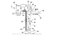
- FIG. 2 is a schematic configuration diagram of an air lift pump according to another embodiment of the present invention. 2, the same components as those in FIG. 1 are denoted by the same reference numerals, and detailed description thereof is omitted.
- the air lift pump 1 ′ shown in FIG. 2 is provided with a gas-liquid separator 40 in the upper part of the main pipe 10 in the air lift pump 1 shown in FIG. 1, and a gas outlet 42 of the gas-liquid separator 40 is introduced into the working pipe 20.
- the working fluid is configured to circulate with a phase change.
- the reflux pipe 50 includes a compressor 52 that heats the vapor-phase working fluid separated by the gas-liquid separator 40 by adiabatic compression, a heat radiating portion 54 that cools the working fluid heated by the compressor 52, and a heat radiating portion 54. And an expander 56 that liquefies the working fluid cooled in step adiabatic expansion, and the working fluid that has passed through the expander 56 is introduced into the working tube 20.
- the heat dissipating part 54 can be composed of a pipe made of a material having good thermal conductivity, and is installed in water at a temperature lower than the temperature of the working fluid passing through the inside, so that the working fluid exchanges heat with external water. To cool. This water temperature may be approximately the same as the water temperature around the heat exchange section 28 of the working tube 20. For example, when the main pipe 10 and the working pipe 20 are installed in the sea, the heat radiating unit 54 may be installed in the sea.
- the working fluid separated by the gas-liquid separator 40 is collected after the water containing the underwater deposit M is collected from the liquid outlet 44 of the gas-liquid separator 40 by the collecting unit 30. Since the gas phase is changed to the liquid phase by passing through the compressor 52, the heat radiating portion 54, and the expander 56, the working fluid introduced into the working pipe 20 is used as a power source that causes an air lift effect in the main pipe 10. Reusable. That is, the air lift pump 1 ′ can be operated only with the liquefaction energy of the working fluid, and the underwater sediment M can be efficiently sucked at low cost even when the installation site is deep. Further, the above-described liquefaction energy of the working fluid can be reduced by installing the heat dissipating part 54 in water in the same manner as the main pipe 10 and the working pipe 20, and further cost reduction and high efficiency can be achieved.
- the reflux pipe 50 is preferably airtightly connected to the gas-liquid separator 40 and the working tube 20 so as to surely prevent the entry of air, which is a non-condensable gas. It is preferable to provide a discharge mechanism such as a discharge valve so that the air can be easily discharged to the outside of the reflux pipe 50.
- the liquid inflow position of the working fluid is lower than the gas phase outflow position so that the heat exchanging section 28 can guide the working fluid upward from the heat insulating section 26 toward the main pipe 10.
- the working fluid that has become a gas phase in the heat exchange unit 28 can be reliably guided to the main pipe 10, and the working fluid can be injected into the main pipe 10 more easily.
- the heat exchanging portion 28 is disposed to be inclined from the heat insulating portion 26 toward the main pipe 10.
- the heat exchange part 28 can also be comprised from the bending piping etc. which have a perpendicular part in part.
- FIG. 3 In order to verify the operation and effect of the present invention, an air lift pump 101 having the configuration shown in FIG. 3 was installed in a water tank and tested.
- FIG. 3 the same components as those in FIGS. 1 and 2 are denoted by the same reference numerals.
- the main pipe 10 has an inner diameter of 11 mm and a length of 1000 mm.
- the heat insulating portion 26 of the working tube 20 was a pipe having an inner diameter of 11 mm and a length of 900 mm, and was insulated from the surroundings by being covered with neoprene sponge.
- the working fluid was HFC-245fa, and the liquid L around the air lift pump 101 was 30 ° C. water.
- the gas-liquid separator 40 and the working tube 20 are connected via a cooler 60 having a Peltier element 62, and the gas-phase working fluid introduced from the gas-liquid separator 40 is liquefied by Peltier cooling, and the working tube 20 to be introduced.
- the liquid phase working fluid at 14 ° C. is 0.013 L / min (0.017 kg / min) in the heat insulating portion 26.
- the working fluid is converted into a gas phase in the heat exchanging section 28 and then introduced into the main pipe 10, whereby the surrounding water L is sucked into the main pipe 10 at a suction flow rate of 30 mL / s (1.8 L). / min).
- the method for suppressing the amount of heat transfer of the main pipe 10 is not particularly limited, for example, the outer peripheral surface of the main pipe 10 is covered with a water-resistant heat insulating material such as urethane foam or polyimide similarly to the heat insulating portion 26 of the working pipe 20.
- a water-resistant heat insulating material such as urethane foam or polyimide similarly to the heat insulating portion 26 of the working pipe 20.
- a configuration in which the main pipe 10 is a double pipe and the inside of the inner pipe and the outside of the outer pipe are thermally insulated by vacuum is exemplified.
- the amount of heat transfer of the main pipe 10 may be appropriately adjusted according to the water depth or the like so that the seawater passing through the main pipe 10 does not freeze.
- the air lift pump 101 ′ shown in FIG. 4 was installed in the water storage tank 110 to verify the operation. 4, the same components as those in FIGS. 1 to 3 are denoted by the same reference numerals.
- the main tube 10 had an inner diameter of 11 mm and a length of 1000 mm.
- the liquid L stored in the water storage tank 110 used 30 ⁇ 1 ° C. water, and the pumping height Hd of the main pipe 10 was set to 300 mm.
- the working fluid was HFC-245fa.
- the working tube 20 forms the heat insulating portion 26 in the same manner as the configuration of FIG. 3, and for the heat exchanging portion 28, a casing in which both wall surfaces 28a and 28b are formed of an aluminum plate having a thickness of 0.5 mm is arranged in the vertical direction.
- the distance Li between the suction port 12 of the main tube 10 and the connection port 22 of the working tube 20 was set to 20 mm.
- the gas-liquid separator 40 is connected to the cooler 60 via the wet flow meter 120 so that the flow rate of the gas-phase working fluid discharged from the gas-liquid separator 40 can be measured.
- the cooler 60 includes a reserve bag 64 that serves as a buffer when adjusting the flow rate of the working fluid, and the heat absorption amount can be controlled in accordance with the flow rate of the working fluid by adjusting the voltage applied to the Peltier element 62.
- the above-described air lift pump 101 ′ is operated for 500 seconds, the flow rate of the working fluid is measured by the wet flow meter 120, and the temperature of the working fluid in the four temperature measuring portions T1 to T4 shown in FIG. 4 is measured.
- Is shown in FIG. 5A shows the flow rate of the working fluid introduced into the cooler 60
- FIG. 5B shows the temperature of each of the temperature measuring units T1 to T4 together with the water temperature in the water storage tank 110. .
- FIGS. 5A and 5B it was confirmed that both the flow rate and temperature were stable.
- 6A, 6B, and 6C correspond to the case where the inner diameter of the main pipe 10 is 8 mm, 11 mm, and 16 mm, respectively, and the water temperature in the water storage tank 110 is 25 ° C., 30 ° C., 35
- the temperature was set to 40 ° C. and 40 ° C., the relationship between Qg and Ql was measured several times.
- compressed air was used as the working fluid introduced into the main pipe 10, and the relationship between the above Qg and Ql was measured.
- the pumping characteristics of the air lift pump 101 'according to the present invention showed the same tendency as the pumping characteristics of the conventional air lift pump. That is, it was confirmed that the existing knowledge about the pumping characteristics can be used for the phase change air lift pump of the present invention.
- As a method for predicting the pumped amount of a conventional air lift pump there is known a method of numerical calculation using the “one-dimensional two-fluid drift flux model” by Hiyama et al. (1989). The numerical calculation result is shown in FIG. When compared with the measurement results of (a) to (c), it was confirmed that they almost coincided as shown in FIG.
Landscapes
- Engineering & Computer Science (AREA)
- Mechanical Engineering (AREA)
- General Engineering & Computer Science (AREA)
- Mining & Mineral Resources (AREA)
- Civil Engineering (AREA)
- Structural Engineering (AREA)
- Jet Pumps And Other Pumps (AREA)
Abstract
【課題】 水中堆積物の吸引を効率良く行うことができるエアリフトポンプを提供する。 【解決手段】 水中に起立状態で設置される主管(10)および作動管(20)を有し、作動管(20)から主管(10)に作動流体を導入することにより、主管(10)の下部に形成された吸引口(12)から堆積物を水と共に吸引して、上方に搬送するエアリフトポンプ(1)であって、作動管(20)は、供給された液相の作動流体を外部の水と断熱した状態で下方に案内する断熱部(22)と、断熱部(22)を経た作動流体を外部の水との熱交換により加熱気化させて主管(10)に供給する熱交換部(24)とを備える。
Description
本発明は、エアリフトポンプおよび水中堆積物の吸引方法に関する。
液体を押し上げるための従来の装置として、フロン等の低沸点作動流体の相変化によるエアリフト効果を利用する構成が知られている。例えば、特許文献1には、作動流体の気泡を上昇管の下部から注入ノズルを介して注入し、上昇管内を温水と共に上昇させる液体押上装置が開示されている。作動流体の気泡は、上昇管の上部に設置された気液分離ドラムで温水と分離された後、空冷コンデンサにより凝縮・液化し、下降管内を自重により降下して再び上昇管の下部に導入される際に、上昇管内の温水により加熱されて沸騰気泡となる。
また、特許文献2には、エアリフトパイプを海中に設置して、海底の鉱物等を海水と共に吸引する深底資源吸引装置が開示されている。レアアース、マンガン団塊等の海底資源は、我が国の資源の安定供給の要となる極めて重要な国内資源であり、その開発と利用が期待されている。海底からの揚鉱システムとしては、エアリフト式以外にポンプ式やバケット式等も知られているが、生産性およびメンテナンス性を両立させる点では、エアリフト式が有望である。
ところが、上記の特許文献1に開示された液体押上装置を、海底資源の採取等のために海中などの水中で使用する場合、以下のような問題があった。すなわち、この液体押上装置は、上昇管内の温水温度と、下降管の周囲温度との温度差を利用して、作動流体の相変化を生じさせるように構成されているので、海中のように上昇管の内外で十分な温度差が生じない状況で使用すると、作動流体に所望の相変化が生じず、運転を継続的に行うことが困難であった。
また、この液体押上装置は、作動流体の上昇管への注入が液相で行われ、上昇管内で加熱されて気相になるように構成されているので、作動流体の相変化を生じさせるための機構を上昇管の内部に設ける必要があり、この相変化部の構成が煩雑になるだけでなく、吸引する土砂等による相変化部の損傷等の問題が生じるおそれがあった。
このため、従来のエアリフト式の揚鉱システムは、上記特許文献2に開示された圧送ポンプ等のように、作動流体を管内に導入するための動力源が必要とされており、この動力源の負荷は、注入深度が深くなるほど大きくなることから、低コストで省エネルギー化を実現するポンプシステムの開発が求められていた。
そこで、本発明は、水中堆積物の吸引を効率良く行うことができるエアリフトポンプおよび水中堆積物の吸引方法の提供を目的とする。
本発明の前記目的は、水中に起立状態で設置される主管および作動管を有し、前記作動管から前記主管に作動流体を導入することにより、前記主管の下部に形成された吸引口から堆積物を水と共に吸引して、上方に搬送するエアリフトポンプであって、前記作動管は、供給された液相の作動流体を外部の水と断熱した状態で下方に案内する断熱部と、前記断熱部を経た作動流体を外部の水との熱交換により加熱気化させて前記主管に供給する熱交換部とを備えるエアリフトポンプにより達成される。
このエアリフトポンプにおいて、前記熱交換部は、前記断熱部から前記主管に向けて作動流体を上方に案内することが好ましい。
また、前記主管を上昇する気相の作動流体を回収する気液分離器と、回収された作動流体を圧縮加熱する圧縮機と、水中に設置されて前記圧縮機からの作動流体を外部の水と熱交換して冷却する放熱部と、前記放熱部を経た作動流体を膨張液化させる膨張器とを更に備え、前記膨張器を経た液相の作動流体を前記作動管に導入することが好ましい。あるいは、前記主管を上昇する気相の作動流体を回収する気液分離器と、回収された作動流体を冷却して液化する冷却器とを更に備えてもよく、前記冷却器を経た液相の作動流体を前記作動管に導入することも可能である。
また、本発明の前記目的は、主管および作動管を水中に起立状態で設置し、前記作動管から前記主管に作動流体を導入することにより、前記主管の下部に形成された吸引口から堆積物を水と共に吸引して、上方に搬送する水中堆積物の吸引方法であって、前記作動管に供給された液相の作動流体を、外部の水と断熱状態で下方に案内するステップと、前記作動管の下方に案内された液相の作動流体を、外部の水との熱交換により加熱気化させて、前記主管に供給するステップとを備える水中堆積物の吸引方法により達成される。
本発明によれば、水中堆積物の吸引を効率良く行うことができるエアリフトポンプおよび水中堆積物の吸引方法を提供することができる。
以下、本発明の実施の形態について、添付図面を参照して説明する。図1は、本発明の一実施形態に係るエアリフトポンプの概略構成図である。図1に示すように、エアリフトポンプ1は、不図示の支持部材により海水等の水中に起立状態で設置される主管10および作動管20を備えている。本実施形態のエアリフトポンプ1は、上記特許文献1に開示された閉鎖ループ内での液体流動装置とは異なり、開放空間での利用が可能な汎用性を有するものである。
主管10は、下端側に吸引口12が形成され、上端側に排出口14が形成されており、吸引口12が海底等の底面近傍に位置することにより、海底鉱物や土砂、汚泥等の水中堆積物を吸引口12から吸引可能に配置されている。排出口14は、海面等の水面よりも上方に位置しており、吸引口12から海水等の水と共に吸引された水中堆積物が排出口14から排出されて、回収部30に回収される。主管10の起立状態は、直立状態であることが好ましいが、傾斜状態であってもよい。
作動管20は、下端側の接続口22が、主管10の吸引口12の上方に接続されている。作動管20の上端側には導入口24が形成されており、液状の作動流体が導入口24から作動管20に導入される。また、作動管20は、断熱部26および熱交換部28を備えており、導入口24側に断熱部26が配置され、接続口22側に熱交換部28が配置されている。作動管20の起立状態は直立状態のみならず傾斜状態であってもよい。
断熱部26は、内部を通過する作動流体を、外部の水と断熱した状態で下方に案内する。断熱部26の具体的構成は、特に限定されないが、例えば、作動流体が通過する配管の外周面をウレタンフォームやポリイミド等の耐水性断熱材で被覆した構成、二重管を用いて内管内部の作動流体と外管外部の水とを真空断熱する構成等を挙げることができる。
熱交換部28は、内部を通過する作動流体を、外部の水との熱交換により加熱気化させて、主管10に供給する。熱交換部28は、例えばアルミニウム合金等の熱伝導性に優れる金属管から構成することができ、作動流体の気化に必要な伝熱面積を確保するために、適宜湾曲させてもよい。断熱部26が、配管を断熱材等で被覆して構成される場合には、配管の一部を露出させて熱交換部28とすることができる。作動流体は、液密度が周囲液相(例えば海水)の密度以上であり、沸点が周囲液相の温度以下であり、周囲液相に対して不溶性または難溶性であるものを好適に使用することができる。作動流体は、これらの条件に加えて、不燃性または難燃性であり、人体や生物に対して無害であるものを、より好ましく使用することができる。
次に、上記の構成を備えるエアリフトポンプ1を用いて、水中堆積物を吸引する方法を説明する。作動管20には、液状の作動流体を導入口24から供給する。使用する作動流体は、導入時は液相である一方、水中においては熱交換部28での熱交換により気相になるように、エアリフトポンプ1を設置する場所の水温や水圧を考慮して適宜選択すればよい。エアリフトポンプ1を水深が比較的浅い海中に設置する場合、海中において熱交換部28の周囲の海水温よりも低い沸点を有する代替フロン等から適宜選択可能であり、例えば、1,1,1,3,3-ペンタフルオロプロパン(HFC-245fa、沸点:15.3 ℃)を使用することができる。深海底においては、高い水圧によって作動流体の沸点が上昇することから、例えば、HFC-23 (沸点-82℃(1気圧), 0℃(約20気圧))を作動流体として好ましく使用することができる。作動流体は、吹き込む位置の水深等を考慮して決定すればよく、例えば、HFC-22(沸点4℃(約5気圧)), HFC-32(沸点0℃(約7気圧)), HFC-134a(沸点4℃(約3.5気圧))等も使用可能である。
作動管20に導入された作動流体は、断熱部26を通過する間は外部の水との熱交換が遮断されるため、液相の状態が維持される。したがって、作動流体は、断熱部26を自重により下降し、熱交換部28に案内される。そして、作動流体が熱交換部28を通過する間に、外部の水との熱交換により加熱され、大部分が液相から気相に変化して、主管10に供給される。
主管10に供給された作動流体は、水中を気泡Bとなって上昇する。このエアリフト効果により、主管10の吸引部12から海底鉱物等の水中堆積物Mが水と共に吸引され、上方に搬送される。こうして、主管10の排出口14から水と共に排出された水中堆積物Mを、回収部30において回収することができる。回収部30は、例えば底板が網板などからなるコンテナ状に形成することができ、水を底板から排出して水中堆積物Mのみを貯留することができる。主管10に対する作動流体の導入箇所は、本実施形態のように吸引口12の近傍であることが好ましいが、例えば、主管10の中央付近等であっても、吸引口12から水中堆積物Mを吸引することが可能である。
本実施形態のエアリフトポンプ1によれば、作動管20が、液相の作動流体を外部の水と断熱した状態で下方に案内する断熱部26と、断熱部26を経た作動流体を外部の水との熱交換により加熱気化させて主管10に供給する熱交換部28とを備えているので、周囲の水温より沸点が低い作動流体を選択することにより、作動流体を下降させるための動力や、作動流体の相変化を生じさせるための動力を必要とすることなく、主管10の内部に作動流体によるエアリフト効果を生じさせることができる。したがって、水中堆積物の吸引を低コストで効率良く行うことができ、例えば、レアアース、マンガン団塊、メタンハイドレード等の海底資源の吸引、港湾施設やダム等での浚渫工事における土砂の吸引、養殖所、ダム湖、貯水タンク等における汚泥の吸引等、各種の水中堆積物の吸引に好適に使用することができる。
また、作動流体は大部分が気相の状態で主管10に供給されるため、作動流体を水深が深い位置で注入する場合でも、注入エネルギーを軽減して主管10内に作動流体を容易且つ確実に供給することができる。また、従来のように作動流体の相変化部を主管10の内部に設ける必要がないので、相変化部の修理やメンテナンスの問題を解消することができると共に、主管10を流れる流体に固体が含まれる場合にも好適に使用可能である。
更に、作動流体の沸点が周囲の水温よりも低いと、気相の状態で主管10に導入された作動流体が、主管10を上昇する途中で凝縮するおそれがない。したがって、エアリフト効果を安定的に生じさせることができ、水中堆積物の吸引搬送を確実に行うことができる。
作動管20に供給される液相状態での作動流体の密度は、作動管20の周囲における水の密度よりも大きいことが好ましい。このような作動流体を選択することにより、作動管20における液相の作動流体の自重による移動を、エアリフトポンプ1の始動直後から補助動力を要することなく確実に行うことができ、作動流体を搬送するためのエネルギーの低減を図ることができる。
図2は、本発明の他の実施形態に係るエアリフトポンプの概略構成図である。図2において、図1と同様の構成部分については同一の符号を付して、詳細な説明を省略する。
図2に示すエアリフトポンプ1’は、図1に示すエアリフトポンプ1において、主管10の上部に気液分離器40を設けると共に、この気液分離器40の気体出口42を、作動管20の導入口24に還流配管50を介して接続することにより、作動流体が相変化を伴いながら循環するように構成したものである。
還流配管50は、気液分離器40で分離された気相の作動流体を断熱圧縮により加熱する圧縮機52と、圧縮機52で加熱された作動流体を冷却する放熱部54と、放熱部54で冷却された作動流体を断熱膨張により液化させる膨張器56とを備えており、膨張器56を経た作動流体が作動管20に導入される。放熱部54は、熱伝導性が良好な材料からなる配管から構成することができ、内部を通過する作動流体の温度よりも低温の水中に設置されて、作動流体を外部の水との熱交換により冷却する。この水温は、作動管20の熱交換部28の周囲における水温と同程度であればよい。例えば、主管10および作動管20を海中に設置する場合には、放熱部54も海中に設置すればよい。
図2に示すエアリフトポンプ1’によれば、気液分離器40の液体出口44から水中堆積物Mを含む水を回収部30において回収した後、気液分離器40で分離された作動流体が、圧縮機52、放熱部54および膨張器56を通過することにより気相から液相に変化するので、作動管20に導入される作動流体を、主管10内にエアリフト効果を生じさせる動力源として再利用可能となる。すなわち、作動流体の液化エネルギーのみでエアリフトポンプ1’を作動させることができ、設置場所の水深が深い場合であっても、水中堆積物Mを低コストで効率良く吸引することができる。また、上述した作動流体の液化エネルギーは、放熱部54を主管10および作動管20と同様に水中に設置することで軽減可能であり、更なる低コスト化、高効率化を図ることができる。
還流配管50は、不凝縮性ガスである空気の混入を確実に防止できるように、気液分離器40および作動管20に気密に接続されていることが好ましく、また、仮に空気が混入した場合には、この空気を還流配管50の外部に容易に排出できるように、排出弁などの排出機構を備えることが好ましい。
熱交換部28は、断熱部26側から主管10に向けて作動流体を上方に案内することができるように、作動流体の液体流入位置が気相流出位置より低いことが好ましい。この構成によれば、熱交換部28において気相となった作動流体を主管10に確実に案内することができ、主管10への作動流体の注入をより容易に行うことができる。具体的には、図2に示すように、熱交換部28を、断熱部26から主管10に向けて傾斜して配置することが好ましい。あるいは、熱交換部28を、一部に鉛直部を有する屈曲配管等から構成することもできる。
以上、本発明の実施の形態について詳述したが、本発明の具体的な態様は上記実施形態に限定されるものではない。本発明によれば、深海底における資源の引き上げコストを低減でき、海底資源の利用が容易になるので、我が国における資源・エネルギーの安定供給に寄与することができる。また、高効率の吸引装置として、海底資源の吸引以外の用途にも広く適用可能である。
本発明の作用・効果を検証するため、図3に示す構成のエアリフトポンプ101を貯水槽内に設置して試験を行った。なお、図3において、図1および図2と同様の構成部分には、同一の符号を付している。
主管10は、内径を11mm、長さを1000mmとした。作動管20の断熱部26は、内径を11mm、長さを900mmの配管とし、ネオプレンスポンジで被覆することにより周囲と断熱した。作動管20の熱交換部28は、内径を11mm、長さを150mmの配管とし、断熱部26から主管10に向けてθ=60度の角度で直線状に傾斜するように配置した。作動流体はHFC-245faを使用し、エアリフトポンプ101の周囲の液体Lは、30℃の水とした。気液分離器40と作動管20とはペルチェ素子62を備える冷却器60を介して接続し、気液分離器40から導入された気相の作動流体が、ペルチェ冷却により液化して、作動管20に導入されるように構成した。
上記の構成を備えるエアリフトポンプ101は、ペルチェ素子62を110Wの電力で0℃に制御したところ、断熱部26には、14℃の液相の作動流体が0.013 L/min(0.017 kg/min)の流量で導入され、この作動流体が熱交換部28で気相になった後、主管10に導入されることにより、主管10には、周囲の水Lが吸込流量30 mL/s(1.8 L/min)で吸引された。
図3に示すエアリフトポンプ101と同様の構成を備える装置を、水深の深い海中などに設置した場合、主管10内を作動流体が上昇する際に、上昇とともに作動流体の圧力が減少し、膨張により温度が低下する。したがって、主管10への外部からの熱移動量を抑制することにより、主管10出口での作動流体温度、すなわち、冷却器60への流入温度を低下でき、冷却器60での除熱量が少なくなり、効率を向上することができる。主管10の熱移動量を抑制する方法は、特に限定されないが、例えば、作動管20の断熱部26と同様に、主管10の外周面をウレタンフォームやポリイミド等の耐水性断熱材で被覆した構成、主管10を二重管として内管内部と外管外部とを真空断熱する構成等を挙げることができる。主管10の熱移動量の抑制は、主管10内を通過する海水が凍らない程度に、水深等に応じて適宜調整すればよい。
ついで、図4に示すエアリフトポンプ101’を貯水槽110に設置して、作動の検証を行った。図4において、図1から図3と同様の構成部分には、同一の符号を付している。主管10は、内径を11mm、長さを1000mmとした。貯水槽110に貯留される液体Lは30±1℃の水を使用し、主管10の揚水高さHdを300mmに設定した。作動流体はHFC-245faを使用した。作動管20は、図3の構成と同様にして断熱部26を形成し、熱交換部28については、両壁面28a,28bが厚さ0.5mmのアルミ板により形成されたケーシングを鉛直方向に直立させることで、入熱量がケーシング内の液面高さにより調整されるように構成した。主管10の吸引口12と作動管20の接続口22との距離Liは、20mmに設定した。気液分離器40は、湿式流量計120を介して冷却器60と接続し、気液分離器40から排出される気相の作動流体の流量を測定可能にした。冷却器60は、作動流体の流量調整時にバッファとなるリザーブバッグ64を備えており、ペルチェ素子62の印加電圧の調節により、作動流体の流量に応じて吸熱量を制御可能に構成した。
上記のエアリフトポンプ101’を500秒間作動させて、湿式流量計120により作動流体の流量を測定すると共に、図4に示す4か所の測温部T1~T4における作動流体の温度を測定した結果を図5に示す。図5(a)は、冷却器60に導入される作動流体の流量を示しており、図5(b)は、各測温部T1~T4の温度を貯水槽110内の水温と共に示している。図5(a)および(b)から明らかなように、流量および温度のいずれも安定していることを確認した。
次に、図4に示すエアリフトポンプ101’において、内径が異なる3種類(8mm、11mm、16mm)の主管10を用意し、それぞれについて、湿式流量計120が検出する気相の作動流体の流量Qg(ml/s)と、主管10の揚水量Ql(ml/s)との関係を測定した。この結果を図6に示す。
図6(a)、(b)および(c)は、主管10の内径が8mm、11mmおよび16mmである場合にそれぞれ対応しており、貯水槽110内の水温を、25℃、30℃、35℃および40℃に設定した場合において、上記のQgとQlとの関係をそれぞれ複数回ずつ測定した。この結果を従来技術と比較するため、主管10に導入する作動流体として圧縮空気を使用し、上記のQgとQlとの関係を測定した。
図6(a)~(c)のいずれの場合においても、本発明に係るエアリフトポンプ101’の揚水特性は、従来技術のエアリフトポンプの揚水特性と同様の傾向を示した。すなわち、揚水特性に関する既存の知見が、本発明の相変化エアリフトポンプにも利用可能であることを確認した。従来のエアリフトポンプの揚水量を予測する手法としては、畠山ら(1989)による「一次元二流体ドリフトフラックスモデル」を用いて数値計算する方法が知られているが、この数値計算結果を図6(a)~(c)の測定結果と比較すると、図7に示すように両者は概ね一致することを確認した。
1,1’ エアリフトポンプ
10 主管
12 吸引口
20 作動管
26 断熱部
28 熱交換部
30 回収部
40 気液分離器
52 圧縮機
54 放熱部
56 膨張器
60 冷却器
10 主管
12 吸引口
20 作動管
26 断熱部
28 熱交換部
30 回収部
40 気液分離器
52 圧縮機
54 放熱部
56 膨張器
60 冷却器
Claims (5)
- 水中に起立状態で設置される主管および作動管を有し、前記作動管から前記主管に作動流体を導入することにより、前記主管の下部に形成された吸引口から堆積物を水と共に吸引して、上方に搬送するエアリフトポンプであって、
前記作動管は、供給された液相の作動流体を外部の水と断熱した状態で下方に案内する断熱部と、前記断熱部を経た作動流体を外部の水との熱交換により加熱気化させて前記主管に供給する熱交換部とを備えるエアリフトポンプ。 - 前記熱交換部は、前記断熱部から前記主管に向けて作動流体を上方に案内する請求項1に記載のエアリフトポンプ。
- 前記主管を上昇する気相の作動流体を回収する気液分離器と、
回収された作動流体を圧縮加熱する圧縮機と、
水中に設置されて前記圧縮機からの作動流体を外部の水と熱交換して冷却する放熱部と、
前記放熱部を経た作動流体を膨張液化させる膨張器とを更に備え、
前記膨張器を経た液相の作動流体を前記作動管に導入する請求項1に記載のエアリフトポンプ。 - 前記主管を上昇する気相の作動流体を回収する気液分離器と、
回収された作動流体を冷却して液化する冷却器とを更に備え、
前記冷却器を経た液相の作動流体を前記作動管に導入する請求項1に記載のエアリフトポンプ。 - 主管および作動管を水中に起立状態で設置し、前記作動管から前記主管に作動流体を導入することにより、前記主管の下部に形成された吸引口から堆積物を水と共に吸引して、上方に搬送する水中堆積物の吸引方法であって、
前記作動管に供給された液相の作動流体を、外部の水と断熱状態で下方に案内するステップと、
前記作動管の下方に案内された液相の作動流体を、外部の水との熱交換により加熱気化させて、前記主管に供給するステップとを備える水中堆積物の吸引方法。
Priority Applications (1)
| Application Number | Priority Date | Filing Date | Title |
|---|---|---|---|
| JP2016527729A JPWO2015190280A1 (ja) | 2014-06-12 | 2015-05-26 | エアリフトポンプおよび水中堆積物の吸引方法 |
Applications Claiming Priority (2)
| Application Number | Priority Date | Filing Date | Title |
|---|---|---|---|
| JP2014-121184 | 2014-06-12 | ||
| JP2014121184 | 2014-06-12 |
Publications (1)
| Publication Number | Publication Date |
|---|---|
| WO2015190280A1 true WO2015190280A1 (ja) | 2015-12-17 |
Family
ID=54833383
Family Applications (1)
| Application Number | Title | Priority Date | Filing Date |
|---|---|---|---|
| PCT/JP2015/065045 WO2015190280A1 (ja) | 2014-06-12 | 2015-05-26 | エアリフトポンプおよび水中堆積物の吸引方法 |
Country Status (2)
| Country | Link |
|---|---|
| JP (1) | JPWO2015190280A1 (ja) |
| WO (1) | WO2015190280A1 (ja) |
Cited By (4)
| Publication number | Priority date | Publication date | Assignee | Title |
|---|---|---|---|---|
| JP6254645B1 (ja) * | 2016-07-19 | 2017-12-27 | 三井造船株式会社 | ガスハイドレート回収システムおよびガスハイドレート回収方法 |
| WO2018088053A1 (ja) * | 2016-11-11 | 2018-05-17 | 三井造船株式会社 | ガスハイドレート回収方法およびガスハイドレート回収装置 |
| JP2020034439A (ja) * | 2018-08-30 | 2020-03-05 | 株式会社Winビジネスデベロップメント | 浚渫装置 |
| WO2022173493A1 (en) * | 2021-02-09 | 2022-08-18 | Matt Hutcheson | Hydroelectricity production using changes in water column density to induce vertical flow |
Families Citing this family (1)
| Publication number | Priority date | Publication date | Assignee | Title |
|---|---|---|---|---|
| CN113294125B (zh) * | 2021-04-26 | 2022-05-27 | 西南石油大学 | 一种海底天然气水合物气举开采装置 |
Citations (2)
| Publication number | Priority date | Publication date | Assignee | Title |
|---|---|---|---|---|
| US4397612A (en) * | 1979-02-22 | 1983-08-09 | Kalina Alexander Ifaevich | Gas lift utilizing a liquefiable gas introduced into a well |
| JPH01155099A (ja) * | 1987-12-11 | 1989-06-16 | Kajima Corp | 低沸点媒体による液体押上装置 |
-
2015
- 2015-05-26 WO PCT/JP2015/065045 patent/WO2015190280A1/ja active Application Filing
- 2015-05-26 JP JP2016527729A patent/JPWO2015190280A1/ja active Pending
Patent Citations (2)
| Publication number | Priority date | Publication date | Assignee | Title |
|---|---|---|---|---|
| US4397612A (en) * | 1979-02-22 | 1983-08-09 | Kalina Alexander Ifaevich | Gas lift utilizing a liquefiable gas introduced into a well |
| JPH01155099A (ja) * | 1987-12-11 | 1989-06-16 | Kajima Corp | 低沸点媒体による液体押上装置 |
Cited By (7)
| Publication number | Priority date | Publication date | Assignee | Title |
|---|---|---|---|---|
| JP6254645B1 (ja) * | 2016-07-19 | 2017-12-27 | 三井造船株式会社 | ガスハイドレート回収システムおよびガスハイドレート回収方法 |
| WO2018016296A1 (ja) * | 2016-07-19 | 2018-01-25 | 三井造船株式会社 | ガスハイドレート回収システムおよびガスハイドレート回収方法 |
| JP2018012915A (ja) * | 2016-07-19 | 2018-01-25 | 三井造船株式会社 | ガスハイドレート回収システムおよびガスハイドレート回収方法 |
| CN109690022A (zh) * | 2016-07-19 | 2019-04-26 | 三井易艾斯控股有限公司 | 气体水合物回收系统及气体水合物回收方法 |
| WO2018088053A1 (ja) * | 2016-11-11 | 2018-05-17 | 三井造船株式会社 | ガスハイドレート回収方法およびガスハイドレート回収装置 |
| JP2020034439A (ja) * | 2018-08-30 | 2020-03-05 | 株式会社Winビジネスデベロップメント | 浚渫装置 |
| WO2022173493A1 (en) * | 2021-02-09 | 2022-08-18 | Matt Hutcheson | Hydroelectricity production using changes in water column density to induce vertical flow |
Also Published As
| Publication number | Publication date |
|---|---|
| JPWO2015190280A1 (ja) | 2017-06-08 |
Similar Documents
| Publication | Publication Date | Title |
|---|---|---|
| WO2015190280A1 (ja) | エアリフトポンプおよび水中堆積物の吸引方法 | |
| US4290266A (en) | Electrical power generating system | |
| US7900452B2 (en) | Clathrate ice thermal transport for ocean thermal energy conversion | |
| CN1690360B (zh) | 一种海底天然气水合物的开采方法及系统 | |
| JP5612096B2 (ja) | 加熱される液体のための自立型ポンプ、およびこれを用いた熱駆動式の液体閉ループ自動循環システム | |
| RU2416002C1 (ru) | Система для температурной стабилизации основания сооружений на вечномерзлых грунтах | |
| JP2014202149A (ja) | 地熱発電システム | |
| EP2395241A2 (en) | Offshore floating platform with ocean thermal energy conversion system | |
| JP5067692B2 (ja) | サイフォン式循環型ヒートパイプ | |
| NO20120557A1 (no) | Undervanns hydrokarbontransport- og temperaturreguleringsanordning | |
| RU2012126403A (ru) | Накопительный резервуар с разделительными перегородками | |
| JP7269674B2 (ja) | 地熱発電システム | |
| JP2009092350A (ja) | 地中熱採取用管、地中熱交換器及び地中熱利用のヒートポンプ | |
| KR20090099517A (ko) | 지열 교환 시스템 및 방법 | |
| TW201018785A (en) | Ocean thermal energy conversion power plant and condensor thereof | |
| US20100193152A1 (en) | Sawyer-singleton geothermal energy tank | |
| JP2017071959A (ja) | ガス回収装置及び水底メタンハイドレートからのガス回収方法 | |
| CN114017004A (zh) | 深水油气生产井筒模拟试验装置和试验方法 | |
| US20090321040A1 (en) | Methods and systems for hole reclamation for power generation via geo-saturation of secondary working fluids | |
| CN104567060A (zh) | 热虹吸油冷却系统 | |
| CN207194865U (zh) | 一种用于深层地热开采的大跨度水平对接u型井 | |
| CN206430398U (zh) | 一种热虹吸油冷却系统 | |
| KR101358303B1 (ko) | 부유식 해상 구조물 및 이를 이용한 전기 생산 방법 | |
| JP2016215151A (ja) | 流体分離装置及び流体分離方法 | |
| KR20140001267A (ko) | 증기압을 이용한 열에너지 순환장치 |
Legal Events
| Date | Code | Title | Description |
|---|---|---|---|
| 121 | Ep: the epo has been informed by wipo that ep was designated in this application |
Ref document number: 15806159 Country of ref document: EP Kind code of ref document: A1 |
|
| ENP | Entry into the national phase |
Ref document number: 2016527729 Country of ref document: JP Kind code of ref document: A |
|
| NENP | Non-entry into the national phase |
Ref country code: DE |
|
| 122 | Ep: pct application non-entry in european phase |
Ref document number: 15806159 Country of ref document: EP Kind code of ref document: A1 |