WO2015189928A1 - 分析機器制御方法、及び分析機器制御装置、並びに分析機器制御プログラム - Google Patents
分析機器制御方法、及び分析機器制御装置、並びに分析機器制御プログラム Download PDFInfo
- Publication number
- WO2015189928A1 WO2015189928A1 PCT/JP2014/065434 JP2014065434W WO2015189928A1 WO 2015189928 A1 WO2015189928 A1 WO 2015189928A1 JP 2014065434 W JP2014065434 W JP 2014065434W WO 2015189928 A1 WO2015189928 A1 WO 2015189928A1
- Authority
- WO
- WIPO (PCT)
- Prior art keywords
- analysis
- analytical instrument
- sample
- unit
- information
- Prior art date
- Legal status (The legal status is an assumption and is not a legal conclusion. Google has not performed a legal analysis and makes no representation as to the accuracy of the status listed.)
- Ceased
Links
Images



Classifications
-
- G—PHYSICS
- G01—MEASURING; TESTING
- G01N—INVESTIGATING OR ANALYSING MATERIALS BY DETERMINING THEIR CHEMICAL OR PHYSICAL PROPERTIES
- G01N30/00—Investigating or analysing materials by separation into components using adsorption, absorption or similar phenomena or using ion-exchange, e.g. chromatography or field flow fractionation
- G01N30/02—Column chromatography
- G01N30/04—Preparation or injection of sample to be analysed
- G01N30/24—Automatic injection systems
-
- G—PHYSICS
- G01—MEASURING; TESTING
- G01N—INVESTIGATING OR ANALYSING MATERIALS BY DETERMINING THEIR CHEMICAL OR PHYSICAL PROPERTIES
- G01N35/00—Automatic analysis not limited to methods or materials provided for in any single one of groups G01N1/00 - G01N33/00; Handling materials therefor
Definitions
- the present invention relates to an analytical instrument control method for controlling the operation of an analytical instrument having an autosampler, an analytical instrument control apparatus, and an analytical instrument control program.
- sample bottles each containing a different sample are placed at predetermined positions on the sample rack, and the sample rack is set on the autosampler.
- sample setting work dedicated control software is started up on the control computer, and analysis conditions (column temperature, detector wavelength, mobile phase flow rate, etc.) for each sample are set (analysis condition setting work).
- analysis conditions column temperature, detector wavelength, mobile phase flow rate, etc.
- position information (number etc.) of the vial in the sample rack set in the autosampler is input to identify the sample, and the analysis schedule is created using the sample and the previously set analysis conditions (analysis schedule creation) work).
- control software instructs the liquid chromatograph to perform analysis, and controls the operation of each part of the liquid chromatograph (autosampler, column oven, liquid feed pump, detector, etc.) according to the analysis schedule to analyze the sample. (Analysis execution instruction work).
- Liquid chromatographs are used for various purposes. For example, for the purpose of pharmaceutical production control and quality control, many different samples are analyzed under the same conditions. In such a case, the person in charge of analysis usually performs the analysis condition setting work, and the work is divided so that the worker performs the sample setting work, the analysis schedule creation work, and the analysis execution instruction work. Workers are often unskilled people who are not familiar with the structure and control software of liquid chromatographs, so that any work they are in charge of can be easily performed according to the instructions of the person in charge of analysis. It has been devised.
- control software on the same PC is used for analysis condition setting work and analysis schedule creation work.
- analysis conditions are erroneously changed.
- the worker since the worker is often an unskilled person, he / she does not realize that the analysis condition has been changed, and performs an invalid analysis as it is, which wastes samples and time.
- a malicious third party intentionally changes analysis conditions for the purpose of performing an incorrect analysis. Such an action becomes a serious problem in the production control and quality control of pharmaceuticals for which strict standards are established.
- a liquid chromatograph has been described as an example here, a gas chromatograph apparatus, a spectrophotometer, and the like, which are analyzers equipped with an autosampler, have the same problem as described above.
- the problem to be solved by the present invention is an analytical instrument capable of preventing analysis conditions from being changed accidentally or intentionally when analyzing a sample by controlling the operation of an analytical instrument having an autosampler.
- a control method, an analytical instrument control device, and an analytical instrument control program are provided.
- a first aspect of the present invention made to solve the above problems is a method for controlling the operation of an analytical instrument including an autosampler having a plurality of sample placement units, a) According to the input by the first user, create one or more samples and analysis condition information associating the analysis conditions of the one or more samples, b) Accepting input of sample position information related to the position of the sample mounting portion on which at least a part of the one or more samples is set by the second user; c) Create an analysis schedule using the analysis condition information and the sample position information, d) characterized in that it comprises a step of instructing the analytical instrument to execute analysis according to the analysis schedule.
- the first user is typically a responsible person
- the second user is typically an operator engaged in analysis work under the direction of the responsible person.
- the first user determines analysis condition information prior to analysis.
- the second user sets the determined sample at a predetermined position on the sample placement unit, and inputs the sample position information.
- the input by the second user is an input to the analytical instrument or an input to another apparatus communicably connected between the analytical instrument and a control device that controls the operation of the analytical instrument. You can also.
- the contents of the input by the second user are typically numbers and symbols that specify the position of the sample placement unit on which the second user has set the sample, but are not necessarily limited thereto.
- the order in which samples are set on a plurality of sample placement units may be determined in advance, and the second user may input the number of samples. In this case, the number of samples input last time is held, and when the second user inputs the number of samples next, the number is input by the number input from the number next to the number acquired last time. Can be configured.
- the analytical instrument control method when the second user sets a predetermined sample and performs input operation of the sample position information, an analysis schedule is created by combining the sample position information and the analysis conditions.
- the analysis instrument is instructed to execute the analysis.
- the second user can perform analysis work without touching a screen on which analysis conditions can be set or changed.
- the analysis conditions created by the first user when an authentication process for accessing a screen or the like on which analysis conditions can be set or changed is added, the analysis conditions created by the first user are added. However, it can prevent more reliably that it is changed by the 2nd user or a third party.
- the second aspect of the present invention made to solve the above problems is an apparatus for controlling the operation of an analytical instrument provided with an autosampler having a plurality of sample placement units, a) an analysis condition information creation unit that creates analysis condition information in which one or more samples and analysis conditions of the one or more samples are associated with each other according to an input by a first user, and stores the analysis condition information in a storage unit; b) a sample position information receiving unit that receives input of sample position information related to the position of the sample mounting unit on which at least a part of the one or more samples is set by the second user; c) an analysis schedule creation unit that creates an analysis schedule using the analysis condition information and the sample position information; d) When the analysis schedule is created, an analysis execution instructing unit that instructs the analysis device to execute analysis according to the analysis schedule; It is characterized by providing.
- the analytical instrument control device is: e) a user authentication unit that authenticates users before accepting operations related to input or change of analysis conditions; f) It is desirable to provide a change permission setting unit for setting permission / non-permission of an operation for changing the analysis condition or the analysis schedule from the analysis device.
- the analytical instrument control device is: g) A confirmation screen presenting unit for displaying a confirmation screen on the analytical instrument when receiving information on the change of the analysis condition from the analytical instrument may be provided.
- the user authentication unit may be configured to authenticate the user prior to input from the input unit of the analytical instrument control device and / or input from the input unit of the analytical instrument.
- the sample position information may include, as incidental information, sample container storage device information for specifying a sample container storage device, user information for specifying a user, or date and time information. This makes it possible to diversify the sample position information and increase the number of analysis conditions that can be executed in association with different analysis conditions.
- a third aspect of the present invention made to solve the above-described problem is a program for controlling the operation of an analytical instrument including an autosampler having a plurality of sample placement units, the computer, It is operated as the analytical instrument control device of the second aspect.
- the second user sets a predetermined sample on the sample placement unit and sets the sample position information.
- an analysis schedule combining the sample position information and the analysis conditions is created, and the analysis apparatus is instructed to execute the analysis.
- the second user can perform analysis work without touching a screen or the like on which analysis conditions can be set or changed. Therefore, it is possible to prevent the analysis conditions from being changed due to error or intention.
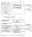
- the principal part block diagram of an example of a liquid chromatograph The figure which shows an example of the sample rack set to a liquid chromatograph. The figure which shows the whole structure of the analysis system containing the apparatus of one Example of the analytical instrument control apparatus which concerns on this invention.
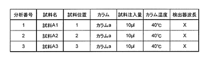
- An example of the analysis condition information used in a present Example An example of (a) analysis condition information and (b) analysis schedule used when incidental information is included in sample position information.
- the analytical instrument control device of this embodiment is a device that controls the operation of a liquid chromatograph having an autosampler.
- FIG. 3 shows the configuration of the liquid chromatograph 10.
- the liquid chromatograph 10 includes an autosampler 30 for introducing a sample, a liquid feed pump 31 for supplying a mobile phase to a flow path, a column oven 32 for maintaining a column to which the sample is introduced at a predetermined temperature, a detector 33, and the like. It has. Furthermore, the liquid chromatograph 10 functionally includes a sample position information holding unit 34 and a sample position information transmitting unit 35.
- the liquid chromatograph of this embodiment is a so-called integrated liquid chromatograph that is integrally provided with an autosampler, a liquid feed pump, a column oven, a detector, and the like, but is a so-called unit that includes each as a single unit. It may be a type of liquid chromatograph.
- FIG. 1 shows a main configuration of the liquid chromatograph 10.
- FIG. 1A is an external view seen from the front
- FIG. 1B is a diagram schematically showing an internal configuration of the apparatus seen from the front.
- the liquid chromatograph 10 includes a display unit 12 and an input unit 13 on the front, and flow path valves 23 and 24 for switching flow paths, a power source, and the like are provided inside. Contained.
- the display unit 12 and the input unit 13 may be provided on a keypad (not shown) connected to the liquid chromatograph 10.
- a sample rack 17 on which a vial 16 containing a sample is placed at a predetermined position is set in the autosampler portion of the liquid chromatograph 10.
- An injection port 22, a washing port (not shown), and a drain (not shown) are arranged on the side of the set sample rack 17.
- a sampling needle moving mechanism 19 for moving the sampling needle 18 in the horizontal direction and the vertical direction is provided.
- the sampling needle moving mechanism 19 includes a plurality of motors. By operating these motors, the sampling needle moving mechanism 19 is moved and the sampling needle 18 is moved up and down. Thereafter, a sample in the vial 16 is collected from the tip of the sampling needle 18 and injected into the injection port 22.
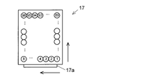
- FIG. 2 is a top view of an example of the sample rack 17 used in this embodiment.
- the sample rack 17 has 96 vial placement units. Each vial mounting part is numbered sequentially from the front side where the handle 17a is provided. It is also possible to use a sample rack having a different number of vial placement units from the illustrated sample rack 17 or a sample rack having a microplate placement unit.
- the analytical instrument control device 60 is connected to the liquid chromatograph 10 via the system controller 50, and has a storage unit 61 as shown in FIG. 3, and includes an analysis condition information creation unit 62, user authentication as functional blocks. A unit 63, a sample position information receiving unit 64, an analysis schedule creating unit 65, an analysis execution instructing unit 66, and a confirmation screen presenting unit 67.
- the storage unit 61 stores user authentication information and analysis condition information created by the person in charge of analysis (corresponding to the first user) in step S1 described later.
- the substance of the analytical instrument control device 60 is a general-purpose computer, and each functional block (portion surrounded by a broken line) is realized by executing an analytical instrument control program by the CPU of the computer.
- the analytical instrument control device 60 is connected to a display unit 70 such as a liquid crystal display and an input unit 80 for performing an input operation.
- a display unit 70 such as a liquid crystal display
- an input unit 80 for performing an input operation.
- the analytical instrument control device 60 is connected to each unit constituting the liquid chromatograph such as an autosampler via the system controller 50.
- the person in charge of analysis launches the analysis instrument control program and calls the analysis condition information creation unit 62.
- the user authentication unit 63 displays an authentication screen for inputting the user ID and password on the display unit 70 to prompt authentication.
- the user ID and password for authentication are issued only to the person in charge of analysis, and an operator or an outsider cannot access a screen for setting analysis conditions.
- the person responsible for analysis performs the authentication (step S1), and then sets the analysis conditions (for example, column a, sample injection volume 10 ⁇ l, column temperature 40 ° C., detector wavelength X, etc.) for different samples to be analyzed. To do.
- the analysis condition information creation unit 62 stores the set analysis condition information in the storage unit 61 (step S2).
- fingerprint authentication and other known methods can be used for user authentication.
- the operator prepares samples and sets each sample on the autosampler 30 (step S3). More specifically, the vial containing the sample is placed on the sample rack 17, and the sample rack 17 is set on the autosampler 30.
- the operator sets the samples A1, ⁇ A2, and A3 to the sample rack positions 1, 2, and 3 (sample rack position numbers shown in FIG. 2) will be described as an example.
- the operator inputs the position numbers 1, 2, and 3 (corresponding to the sample position information of the present invention) where the sample is set from the input unit 13 of the liquid chromatograph 10 (step S4).
- the sample position information holding unit 34 of the liquid chromatograph 10 holds the information (step S5).
- the sample position information transmitting unit 35 transmits the sample position information to the sample position information receiving unit 64 of the analytical instrument control device 60 (step S6).
- the analysis schedule creating unit 65 reads the analysis condition information from the storage unit 61 (step S7), and receives the received sample position information and the analysis. An analysis schedule is created using the conditions (see FIG. 5, step S8).
- the analysis schedule creation unit 65 creates an analysis schedule by combining the sample position information (1 to 3) with the analysis conditions.
- the analysis execution instructing unit 66 instructs the liquid chromatograph 10 to start the analysis based on this (Step S9).
- analysis is started in the liquid chromatograph 10, and sample injection by the autosampler 30 and data collection by the detector are performed.
- output data from the detector 33 is transmitted to the analytical instrument control device 60 and stored in the storage unit 61.
- the analytical instrument control device 60 by disposing the analytical instrument control device 60 at a position physically separated from the liquid chromatograph 10 (for example, a separate room), it is possible to prevent the operator from operating the analytical instrument control device. As a result, it is possible to prevent the analysis conditions from being changed without the operator's knowledge or the analysis condition information being intentionally changed by a malicious third party.
- the operator is allowed to perform only steps S4 and S5 described above, and the analysis conditions are set or changed.
- the analysis work can be performed without accessing the analysis schedule creation unit 65 or the like. Therefore, it is possible to prevent the analysis conditions from being changed by mistake or intentionally.
- the analysis instrument control device 60 that controls the operation of the liquid chromatograph 10 is used.
- other analysis instruments such as a spectroscopic measurement apparatus
- the analytical instrument is a liquid (or gas) chromatograph, it is common to set a large number of samples at once, so that it is possible to prevent accidental or intentional changes in analysis conditions. Is particularly needed. Therefore, particularly when controlling the chromatograph apparatus, the analytical instrument control method and the like according to the present invention can be suitably used.
- sample placement device information related to the date and time, the operator, and the sample placement device (sample rack, etc.) can be added to the above-described sample position information as incidental information.
- analysis condition information as shown in FIG. 6A is created by the responsible person, and the sample and analysis conditions are associated with each other by the sample position information including the worker name.
- An analysis schedule as shown in (b) is created. If comprised in this way, the kind and number of analyzes which can be performed can be increased.
- the analytical instrument information is added to the sample position information as supplementary information, the operation of a plurality of analytical instruments can be controlled by a single analytical instrument control device.
Landscapes
- Physics & Mathematics (AREA)
- Health & Medical Sciences (AREA)
- Life Sciences & Earth Sciences (AREA)
- Chemical & Material Sciences (AREA)
- Analytical Chemistry (AREA)
- Biochemistry (AREA)
- General Health & Medical Sciences (AREA)
- General Physics & Mathematics (AREA)
- Immunology (AREA)
- Pathology (AREA)
- Automatic Analysis And Handling Materials Therefor (AREA)
Abstract
オートサンプラ30を備えた分析機器の動作を制御する分析機器制御装置60において、分析の作業者による試料を載置した試料載置部の位置情報を入力する入力部13と、該試料位置情報の入力を受け付ける試料位置情報受付部64と、分析条件情報と、該試料位置情報を用いて分析スケジュールを作成する分析スケジュール作成部65と、分析スケジュールが作成されると、該分析スケジュールに従って分析機器に分析の実行を指示する分析実行指示部66と、を備える。これにより、オートサンプラを有する分析機器の動作を制御して試料を分析する際に、過失や故意によって分析条件が変更されることを防止することができる。
Description
本発明は、オートサンプラを有する分析機器の動作を制御する分析機器制御方法、及び分析機器制御装置、並びに分析機器制御プログラムに関する。
近年、液体クロマトグラフ等の分析機器では、分析機器本体を操作する代わりに、分析機器と相互に通信可能に接続された制御用コンピュータにインストールされた専用のソフトウェア上で使用者が分析条件を設定し、分析機器に対して分析の実行を指示することが一般的になっている。また、専用のソフトウェアでは、分析機器からの出力データを処理して解析することもできるようになっている(例えば特許文献1)。
オートサンプラを有する液体クロマトグラフを用いた分析では、それぞれ異なる試料を収容した1乃至複数の試料瓶(バイアル)をサンプルラックの予め決められた位置に載置し、そのサンプルラックをオートサンプラにセットする(試料セット作業)。また、制御用コンピュータで専用の制御ソフトウェアを立ち上げ、各試料の分析条件(カラム温度、検出器の波長、移動相の流量等)を設定する(分析条件設定作業)。さらに、オートサンプラにセットしたサンプルラックでのバイアルの位置情報(番号等)を入力して試料を特定し、該試料と先に設定した分析条件とを用いて分析スケジュールを作成する(分析スケジュール作成作業)。最後に、制御ソフトウェアから液体クロマトグラフに対して分析実行を指示し、分析スケジュールに従って液体クロマトグラフの各部(オートサンプラ、カラムオーブン、送液ポンプ、検出器等)の動作を制御して試料の分析を実行させる(分析実行指示作業)。
液体クロマトグラフは様々な目的で使用されるが、例えば医薬品の製造管理や品質管理を目的とする場合には多数の異なる試料を同一の条件で分析する。このような場合には、通常、分析責任者が分析条件設定作業を行い、作業者が試料セット作業、分析スケジュール作成作業、及び分析実行指示作業を行うように作業が切り分けられる。作業者は液体クロマトグラフの構造や制御ソフトウェアに精通していない非熟練者であることが多く、作業者が担当する作業は、いずれも分析責任者の指示に従って簡便に実行することができるように工夫されている。
従来の分析機器制御方法では、分析条件設定作業と分析スケジュール作成作業に同一のPC上の制御ソフトウェアが用いられる。このような構成では、作業者がバイアル番号を入力して分析スケジュールを作成する際に誤って分析条件を変更してしまう可能性がある。上述のとおり作業者は非熟練者であることが多いため、分析条件が変更されていることに気づかず、そのまま無効な分析を実行してしまい、試料や時間を無駄に消費してしまう。また、誤った分析を行わせることを目的として、悪意を持った第三者が分析条件を故意に変更することも考えられる。このような行為は、厳しい基準が設けられている医薬品の製造管理及び品質管理においては、重大な問題となる。
ここでは液体クロマトグラフを一例に挙げて説明したが、オートサンプラを備える分析装置であるガスクロマトグラフ装置、分光光度計等においても上記同様の問題がある。
ここでは液体クロマトグラフを一例に挙げて説明したが、オートサンプラを備える分析装置であるガスクロマトグラフ装置、分光光度計等においても上記同様の問題がある。
本発明が解決しようとする課題は、オートサンプラを有する分析機器の動作を制御することにより試料を分析する際に、過失や故意によって分析条件が変更されることを防止することが可能な分析機器制御方法、及び分析機器制御装置、並びに分析機器制御プログラムを提供することである。
上記課題を解決するために成された本発明の第1の態様は、複数の試料載置部を有するオートサンプラを備えた分析機器の動作を制御する方法であって、
a) 第1の使用者による入力に従って、1乃至複数の試料、及び該1乃至複数の試料の分析条件を対応づけた分析条件情報を作成し、
b) 第2の使用者による、前記1乃至複数の試料のうちの少なくとも一部がセットされた試料載置部の位置に関する試料位置情報の入力を受け付け、
c) 前記分析条件情報と、前記試料位置情報を用いて分析スケジュールを作成し、
d) 前記分析スケジュールに従って前記分析機器に分析の実行を指示する
工程を有することを特徴とする。
a) 第1の使用者による入力に従って、1乃至複数の試料、及び該1乃至複数の試料の分析条件を対応づけた分析条件情報を作成し、
b) 第2の使用者による、前記1乃至複数の試料のうちの少なくとも一部がセットされた試料載置部の位置に関する試料位置情報の入力を受け付け、
c) 前記分析条件情報と、前記試料位置情報を用いて分析スケジュールを作成し、
d) 前記分析スケジュールに従って前記分析機器に分析の実行を指示する
工程を有することを特徴とする。
上記第1の使用者は典型的には責任者であり、上記第2の使用者は典型的には該責任者の指示の元で分析作業に従事する作業者である。第1の使用者は分析に先立って分析条件情報を決定する。第2の使用者は、決められた試料を試料載置部の所定の位置にセットし、試料位置情報を入力する。
上記第2の使用者による入力は、分析機器への入力、あるいは該分析機器と該分析機器の動作を制御する制御装置との間で通信可能に接続された別の装置への入力とすることもできる。なお、分析機器と制御装置の設置場所が離れている場合には、分析機器への入力とすることが好ましい。これにより、第2の使用者が分析機器の設置場所から移動することなく試料のセットと入力を完了することができ、作業効率が高まる。
また、上記第2の使用者による入力の内容は、典型的には、第2の使用者が試料をセットした試料載置部の位置を特定する番号や記号であるが、必ずしもこれに限定されない。例えば、複数の試料載置部に試料をセットする順序を予め決めておき、第2の使用者が試料数を入力するようにしてもよい。この場合には、前回入力された試料数を保持しておき、次に第2の使用者が試料数を入力すると、前回取得した番号の次の番号から入力された数だけ番号を取得するように構成することができる。
本発明に係る分析機器制御方法では、第2の使用者が予め決められた試料をセットしてセットした試料位置情報の入力操作を行うと、試料位置情報と分析条件を組み合わせた分析スケジュールが作成され、分析機器に対して分析の実行が指示される。この方法では、分析条件を設定したり変更したりすることが可能な画面に触れさせることなく第2の使用者に分析作業を行わせることができる。
また、本発明に係る分析機器制御方法において、分析条件を設定したり変更したりすることが可能な画面等にアクセスするための認証工程を追加すると、第1の使用者により作成された分析条件が、第2の使用者や第三者によって変更されるのをより確実に防ぐことができる。
また、本発明に係る分析機器制御方法において、分析条件を設定したり変更したりすることが可能な画面等にアクセスするための認証工程を追加すると、第1の使用者により作成された分析条件が、第2の使用者や第三者によって変更されるのをより確実に防ぐことができる。
上記課題を解決するために成された本発明の第2の態様は、複数の試料載置部を有するオートサンプラを備えた分析機器の動作を制御する装置であって、
a) 第1の使用者による入力に従って、1乃至複数の試料、及び該1乃至複数の試料の分析条件を対応づけた分析条件情報を作成して記憶部に保存する分析条件情報作成部と、
b) 第2の使用者による、前記1乃至複数の試料のうちの少なくとも一部がセットされた試料載置部の位置に関する試料位置情報の入力を受け付ける試料位置情報受付部と、
c) 前記分析条件情報と、前記試料位置情報を用いて分析スケジュールを作成する分析スケジュール作成部と、
d) 前記分析スケジュールが作成されると、該分析スケジュールに従って前記分析機器に分析の実行を指示する分析実行指示部と、
を備えることを特徴とする。
a) 第1の使用者による入力に従って、1乃至複数の試料、及び該1乃至複数の試料の分析条件を対応づけた分析条件情報を作成して記憶部に保存する分析条件情報作成部と、
b) 第2の使用者による、前記1乃至複数の試料のうちの少なくとも一部がセットされた試料載置部の位置に関する試料位置情報の入力を受け付ける試料位置情報受付部と、
c) 前記分析条件情報と、前記試料位置情報を用いて分析スケジュールを作成する分析スケジュール作成部と、
d) 前記分析スケジュールが作成されると、該分析スケジュールに従って前記分析機器に分析の実行を指示する分析実行指示部と、
を備えることを特徴とする。
ところで、分析機器によっては、分析機器側から制御装置に分析条件の変更を指示し、分析条件情報の書き換えを指示する機能を有するものがある。
そこで、本発明に係る分析機器制御装置は、
e) 分析条件の入力や変更に係る操作を受け付ける前に使用者の認証を行う使用者認証部や、
f) 前記分析機器から前記分析条件や前記分析スケジュールを変更する操作の許可・不許可を設定する変更許可設定部
を備えることが望ましい。また、本発明に係る分析機器制御装置は、
g) 前記分析機器から分析条件の変更に関する情報を受信すると、該分析機器に確認画面を表示させる確認画面提示部
を備えるようにしてもよい。なお、前記使用者認証部は、分析機器制御装置の入力部からの入力及び/又は分析機器の入力部からの入力に先立って使用者の認証を行うように構成することができる。
そこで、本発明に係る分析機器制御装置は、
e) 分析条件の入力や変更に係る操作を受け付ける前に使用者の認証を行う使用者認証部や、
f) 前記分析機器から前記分析条件や前記分析スケジュールを変更する操作の許可・不許可を設定する変更許可設定部
を備えることが望ましい。また、本発明に係る分析機器制御装置は、
g) 前記分析機器から分析条件の変更に関する情報を受信すると、該分析機器に確認画面を表示させる確認画面提示部
を備えるようにしてもよい。なお、前記使用者認証部は、分析機器制御装置の入力部からの入力及び/又は分析機器の入力部からの入力に先立って使用者の認証を行うように構成することができる。
前記試料位置情報は、試料容器収容器具を特定する試料容器収容器具情報、使用者を特定する使用者情報、又は日時に関する情報を付帯情報として含むものとすることができる。これにより、試料位置情報を多様化し、それらに異なる分析条件を対応付けて実行可能な分析条件の数を増やすことができる。なお、使用者による付帯情報の誤入力を防ぐ観点から、前記試料位置情報取得部が付帯情報を自動的に取得するように構成することが好ましい。
上記課題を解決するために成された本発明の第3の態様は、複数の試料載置部を有するオートサンプラを備えた分析機器の動作を制御するためのプログラムであって、コンピュータを、上記第2の態様の分析機器制御装置として動作させることを特徴とする。
本発明に係る分析機器制御方法及び分析機器制御装置並びに分析機器制御プログラムを用いた試料の分析では、第2の使用者が予め決められた試料を試料載置部にセットして試料位置情報の入力操作を行うと、試料位置情報と分析条件を組み合わせた分析スケジュールが作成され、分析機器に対して分析の実行が指示される。この方法では、分析条件を設定したり変更したりすることが可能な画面等に触れさせることなく第2の使用者に分析作業を行わせることができる。従って、過失や故意によって分析条件が変更されることを防止することができる。
以下、本発明に係る分析機器制御方法、分析機器制御装置、及び分析機器制御プログラムの一実施例について説明する。
本実施例の分析機器制御装置はオートサンプラを有する液体クロマトグラフの動作を制御する装置である。
本実施例の分析機器制御装置はオートサンプラを有する液体クロマトグラフの動作を制御する装置である。
図3に液体クロマトグラフ10の構成を示す。液体クロマトグラフ10は、試料を導入するオートサンプラ30、移動相を流路に供給する送液ポンプ31、試料が導入されるカラムを所定の温度に維持するためのカラムオーブン32、検出器33等を備えている。さらに、液体クロマトグラフ10は、機能的に、試料位置情報保持部34と、試料位置情報送信部35を備えている。本実施例の液体クロマトグラフは、オートサンプラ、送液ポンプ、カラムオーブン、及び検出器などを一体的に備える、いわゆる一体型の液体クロマトグラフであるが、それぞれを単体のユニットとして備える、いわゆるユニット型の液体クロマトグラフであってもよい。
図1に液体クロマトグラフ10の要部構成を示す。図1(a)は正面から見た外観、図1(b)は正面から見た装置内部の構成を模式的に示す図である。図1(a)に示すように、液体クロマトグラフ10は、正面に表示部12と入力部13を備えており、内部には流路を切り替えるための流路バルブ23、24や、電源等が収容されている。なお、表示部12および入力部13は、液体クロマトグラフ10と接続したキーパッド(図示なし)上に設けられることもある。
図1(b)に示すように、液体クロマトグラフ10のオートサンプラ部には、試料を収容したバイアル16が所定の位置に載置されたサンプルラック17がセットされる。セットされたサンプルラック17の側方にはインジェクションポート22、洗浄ポート(図示なし)、ドレイン(図示なし)が配置されている。これらの上部には、サンプリングニードル18を水平方向及び垂直方向に移動するためのサンプリングニードル移動機構19が設けられている。サンプリングニードル移動機構19の内部には複数のモータが内蔵されており、このモータを動作させることによって、サンプリングニードル移動機構19を移動させるとともに、サンプリングニードル18を上下動させる。その後、サンプリングニードル18の先端からバイアル16内の試料が採取され、インジェクションポート22に注入される。
図2は、本実施例において用いられるサンプルラック17の一例の上面図である。このサンプルラック17は96個のバイアル載置部を有している。各バイアル載置部には取っ手17aが設けられた手前側から順に番号が付されている。なお、図示したサンプルラック17と異なる数のバイアル載置部を有するサンプルラックやマイクロプレートの載置部を有するサンプルラックを用いることもできる。
分析機器制御装置60は、システムコントローラ50を介して液体クロマトグラフ10に接続されており、図3に示すように、記憶部61を有し、機能ブロックとして分析条件情報作成部62、使用者認証部63、試料位置情報受付部64、分析スケジュール作成部65、分析実行指示部66、及び確認画面提示部67を備えている。記憶部61には、使用者認証情報と、後述するステップS1において分析責任者(第1の使用者に相当)により作成される分析条件情報が保存される。分析機器制御装置60の実体は汎用のコンピュータであり、上記の各機能ブロック(破線で囲んだ部分)は、該コンピュータのCPUによって分析機器制御プログラムを実行することにより具現化される。また、分析機器制御装置60には、液晶ディスプレイ等からなる表示部70と、入力操作を行うための入力部80が接続されている。
なお、前述したユニット型の液体クロマトグラフの場合、分析機器制御装置60は、システムコントローラ50を介してオートサンプラなど液体クロマトグラフを構成する各ユニットにそれぞれ接続される。
なお、前述したユニット型の液体クロマトグラフの場合、分析機器制御装置60は、システムコントローラ50を介してオートサンプラなど液体クロマトグラフを構成する各ユニットにそれぞれ接続される。
以下、図4のフローチャートを参照して、本実施例における分析機器制御方法を説明する。なお、フローチャートにおいて二重枠線で囲んだステップが作業者(第2の使用者に相当)により行われる。
はじめに、分析責任者が分析機器制御プログラムを立ち上げて分析条件情報作成部62を呼び出す。すると、使用者認証部63が表示部70に使用者IDとパスワードを入力する認証画面を表示して認証を促す。認証用の使用者IDとパスワードは、分析責任者にのみ発行され、作業者や部外者が分析条件を設定する画面にアクセスできないようになっている。分析責任者は認証を行った後(ステップS1)、分析の対象とする複数の異なる試料の分析条件(例えば、カラムa、試料注入量10μl、カラム温度40℃、検出器波長X等)を設定する。分析条件情報作成部62は、設定された分析条件情報を記憶部61に保存する(ステップS2)。なお、使用者の認証には、上記の方法以外にも、指紋認証や、その他周知の方法を用いることができる。
作業者は、試料を準備し、各試料をオートサンプラ30にセットする(ステップS3)。より詳しくは、試料が収容されたバイアルをサンプルラック17に載置し、サンプルラック17をオートサンプラ30にセットする。以下、作業者が試料A1, A2, A3をサンプルラックの位置1, 2, 3(図2に示したサンプルラックの位置の番号)にそれぞれセットした場合を例に説明する。
続いて、作業者は、液体クロマトグラフ10の入力部13から、試料をセットした位置の番号1, 2, 3(本発明の試料位置情報に相当)を入力する(ステップS4)。試料位置情報が入力されると、液体クロマトグラフ10の試料位置情報保持部34はその情報を保持する(ステップS5)。また、試料位置情報送信部35は分析機器制御装置60の試料位置情報受付部64に試料位置情報を送信する(ステップS6)。
ここでは、作業者が試料をセットした位置の番号を個別に入力する例を説明したが、サンプルラック17の位置1から96まで試料瓶(バイアル)を順番にセットする場合には、作業者がセットした試料数(ここでは「3」)を入力してもよい。この場合、作業者によりセットされた試料数の分だけ1から順に(ここでは1~3まで)位置が取得されて試料位置情報受付部64にその情報が送信される。また、取得した位置の最大値(ここでは「3」)は試料位置情報保持部34に保持され、次に作業者が試料数を入力したときにその数(ここでは「3」)が読み出されて、4から順に試料数の分だけ位置が取得される。例えば、一度にセットする試料の数が多い場合にはこのように構成することで作業者による入力の手間を省き、作業効率を高めることができる。
分析機器制御装置60の試料位置情報受付部64が試料位置情報を受信すると、分析スケジュール作成部65は、記憶部61から分析条件情報を読み出して(ステップS7)、受信した試料位置情報と、分析条件を用いて分析スケジュールを作成する(図5参照。ステップS8)。ここでは、分析スケジュール作成部65は、試料位置情報(1~3)に分析条件を組み合わせて分析スケジュールを作成する。
分析スケジュールが作成されると、分析実行指示部66は、これに基づいて液体クロマトグラフ10に分析開始を指示する(ステップS9)。これにより液体クロマトグラフ10で分析が開始され、オートサンプラ30による試料の注入や検出器によるデータ採取が行われる。分析開始後は、検出器33からの出力データが分析機器制御装置60に送信され、記憶部61に保存される。
また、分析機器制御装置60を液体クロマトグラフ10と物理的に離れた位置(たとえば別室)に配置することで、作業者による分析機器制御装置の操作を防止することができる。これにより、作業者が気づかないうちに分析条件を変更したり、悪意を持った第三者により故意に分析条件情報が変更されたりするのを防止できる。
上述のとおり、本実施例の分析機器制御方法、分析機器制御装置、及び分析機器制御プログラムを用いると、作業者に上述のステップS4及びS5のみ行わせ、分析条件を設定したり変更したりすることが可能な分析スケジュール作成部65等にアクセスさせずに分析作業を行わせることができる。従って、過失や故意によって分析条件が変更されることを防止できる。
上記の実施例は一例であって、本発明の趣旨に沿って適宜に変更することができる。
上記実施例では、液体クロマトグラフ10の動作を制御する分析機器制御装置60としたが、オートサンプラを有する他の分析機器(分光測定装置等)についても同様に構成することができる。なお、分析機器が液体(あるいはガス)クロマトグラフ装置である場合には、一度に多数の試料をセットすることが一般的であるため、過失や故意によって分析条件が変更されるのを防止することが特に必要とされる。従って、特にクロマトグラフ装置を制御する際に、本発明に係る分析機器制御方法等を好適に用いることができる。
上記実施例では、液体クロマトグラフ10の動作を制御する分析機器制御装置60としたが、オートサンプラを有する他の分析機器(分光測定装置等)についても同様に構成することができる。なお、分析機器が液体(あるいはガス)クロマトグラフ装置である場合には、一度に多数の試料をセットすることが一般的であるため、過失や故意によって分析条件が変更されるのを防止することが特に必要とされる。従って、特にクロマトグラフ装置を制御する際に、本発明に係る分析機器制御方法等を好適に用いることができる。
また、上述の試料位置情報に、付帯情報として日時や作業者、試料載置器具(サンプルラック等)に関する情報を追加することができる。例えば作業者情報を追加する場合には、責任者によって図6(a)に示すような分析条件情報が作成され、作業者名を含む試料位置情報によって試料と分析条件が対応付けられ、図6(b)に示すような分析スケジュールが作成される。このように構成すると、実行可能な分析の種類や数を増やすことができる。また、分析機器情報を付帯情報として試料位置情報に追加すると、1つの分析機器制御装置によって複数の分析機器の動作を制御することもできる。
10…液体クロマトグラフ
12…表示部
13…入力部
16…バイアル
17…サンプルラック
30…オートサンプラ
31…送液ポンプ
32…カラムオーブン
33…検出器
34…試料位置情報保持部
35…試料位置情報送信部
50…システムコントローラ
60…分析機器制御装置
61…記憶部
62…分析条件情報作成部
63…使用者認証部
64…試料位置情報受付部
65…分析スケジュール作成部
66…分析実行指示部
67…確認画面提示部
70…表示部
80…入力部
12…表示部
13…入力部
16…バイアル
17…サンプルラック
30…オートサンプラ
31…送液ポンプ
32…カラムオーブン
33…検出器
34…試料位置情報保持部
35…試料位置情報送信部
50…システムコントローラ
60…分析機器制御装置
61…記憶部
62…分析条件情報作成部
63…使用者認証部
64…試料位置情報受付部
65…分析スケジュール作成部
66…分析実行指示部
67…確認画面提示部
70…表示部
80…入力部
Claims (8)
- 複数の試料載置部を有するオートサンプラを備えた分析機器の動作を制御する方法であって、
a) 第1の使用者による入力に従って、1乃至複数の試料、及び該1乃至複数の試料の分析条件を対応づけた分析条件情報を作成し、
b) 第2の使用者による、前記1乃至複数の試料のうちの少なくとも一部がセットされた試料載置部の位置に関する試料位置情報の入力を受け付け、
c) 前記分析条件情報と、前記試料位置情報を用いて分析スケジュールを作成し、
d) 前記分析スケジュールに従って前記分析機器に分析の実行を指示する
工程を有することを特徴とする分析機器制御方法。 - e) 分析条件を設定したり変更したりすることが可能な分析スケジュール設定画面等にアクセスするために使用者の認証を行う
工程を有することを特徴とする請求項1に記載の分析機器制御方法。 - 前記試料位置情報が、試料容器収容器具を特定する試料容器収容器具情報、使用者を特定する使用者情報、日時に関する情報、又は分析機器を特定する情報を付帯情報として含むことを特徴とする請求項1又は2に記載の分析機器制御方法。
- 複数の試料載置部を有するオートサンプラを備えた分析機器の動作を制御する装置であって、
a) 第1の使用者による入力に従って、1乃至複数の試料、及び該1乃至複数の試料の分析条件を対応づけた分析条件情報を作成して記憶部に保存する分析条件情報作成部と、
b) 第2の使用者による、前記1乃至複数の試料のうちの少なくとも一部がセットされた試料載置部の位置に関する試料位置情報の入力を受け付ける試料位置情報受付部と、
c) 前記分析条件情報と、前記試料位置情報を用いて分析スケジュールを作成する分析スケジュール作成部と、
d) 前記分析スケジュールが作成されると、該分析スケジュールに従って前記分析機器に分析の実行を指示する分析実行指示部と、
を備えることを特徴とする分析機器制御装置。 - e) 分析条件の入力や変更に係る操作を受け付ける前に使用者の認証を行う使用者認証部
を備えることを特徴とする請求項4に記載の分析機器制御装置。 - f) 前記分析機器から前記分析条件や前記分析スケジュールを変更する操作の許可・不許可を設定する変更許可設定部
を備えることを特徴とする請求項4又は5に記載の分析機器制御装置。 - g) 前記分析機器から分析条件の変更に関する情報を受信すると、該分析機器に確認画面を表示させる確認画面提示部
を備えること特徴とする請求項4から6のいずれかに記載の分析機器制御装置。 - 複数の試料載置部を有するオートサンプラを備えた分析機器の動作を制御するために、コンピュータを請求項4から7のいずれかに記載の分析器制御装置として機能させることを特徴とする分析機器制御プログラム。
Priority Applications (1)
| Application Number | Priority Date | Filing Date | Title |
|---|---|---|---|
| PCT/JP2014/065434 WO2015189928A1 (ja) | 2014-06-11 | 2014-06-11 | 分析機器制御方法、及び分析機器制御装置、並びに分析機器制御プログラム |
Applications Claiming Priority (1)
| Application Number | Priority Date | Filing Date | Title |
|---|---|---|---|
| PCT/JP2014/065434 WO2015189928A1 (ja) | 2014-06-11 | 2014-06-11 | 分析機器制御方法、及び分析機器制御装置、並びに分析機器制御プログラム |
Publications (1)
| Publication Number | Publication Date |
|---|---|
| WO2015189928A1 true WO2015189928A1 (ja) | 2015-12-17 |
Family
ID=54833059
Family Applications (1)
| Application Number | Title | Priority Date | Filing Date |
|---|---|---|---|
| PCT/JP2014/065434 Ceased WO2015189928A1 (ja) | 2014-06-11 | 2014-06-11 | 分析機器制御方法、及び分析機器制御装置、並びに分析機器制御プログラム |
Country Status (1)
| Country | Link |
|---|---|
| WO (1) | WO2015189928A1 (ja) |
Cited By (2)
| Publication number | Priority date | Publication date | Assignee | Title |
|---|---|---|---|---|
| JP2020038199A (ja) * | 2018-08-31 | 2020-03-12 | 株式会社日立ハイテクサイエンス | クロマトグラフ装置 |
| CN112461980A (zh) * | 2019-09-06 | 2021-03-09 | 株式会社岛津制作所 | 分析系统、分析辅助装置、分析方法以及分析辅助方法 |
Citations (3)
| Publication number | Priority date | Publication date | Assignee | Title |
|---|---|---|---|---|
| JPH10197509A (ja) * | 1996-12-27 | 1998-07-31 | Shimadzu Corp | 分析装置のデータ管理装置 |
| JP2006277577A (ja) * | 2005-03-30 | 2006-10-12 | Hitachi High-Technologies Corp | 処理装置及び処理装置システム |
| JP2009019913A (ja) * | 2007-07-10 | 2009-01-29 | Hitachi High-Technologies Corp | 分析装置 |
-
2014
- 2014-06-11 WO PCT/JP2014/065434 patent/WO2015189928A1/ja not_active Ceased
Patent Citations (3)
| Publication number | Priority date | Publication date | Assignee | Title |
|---|---|---|---|---|
| JPH10197509A (ja) * | 1996-12-27 | 1998-07-31 | Shimadzu Corp | 分析装置のデータ管理装置 |
| JP2006277577A (ja) * | 2005-03-30 | 2006-10-12 | Hitachi High-Technologies Corp | 処理装置及び処理装置システム |
| JP2009019913A (ja) * | 2007-07-10 | 2009-01-29 | Hitachi High-Technologies Corp | 分析装置 |
Cited By (4)
| Publication number | Priority date | Publication date | Assignee | Title |
|---|---|---|---|---|
| JP2020038199A (ja) * | 2018-08-31 | 2020-03-12 | 株式会社日立ハイテクサイエンス | クロマトグラフ装置 |
| JP7337573B2 (ja) | 2018-08-31 | 2023-09-04 | 株式会社日立ハイテクサイエンス | クロマトグラフ装置 |
| CN112461980A (zh) * | 2019-09-06 | 2021-03-09 | 株式会社岛津制作所 | 分析系统、分析辅助装置、分析方法以及分析辅助方法 |
| CN112461980B (zh) * | 2019-09-06 | 2023-10-24 | 株式会社岛津制作所 | 分析系统、分析辅助装置、分析方法以及分析辅助方法 |
Similar Documents
| Publication | Publication Date | Title |
|---|---|---|
| US20170089870A1 (en) | Sample introduction system | |
| JP6264997B2 (ja) | 自動分析装置用制御装置 | |
| US10191620B2 (en) | Sample-analyzing system | |
| US11499984B2 (en) | Pretreatment apparatus and analysis system comprising the same | |
| JP5637313B2 (ja) | 液体クロマトグラフ用制御装置及びプログラム | |
| US20150066388A1 (en) | Automatic analysis control device and program | |
| JP2014029270A (ja) | 分析機器制御装置 | |
| WO2014068786A1 (ja) | クロマトグラフ分析装置 | |
| JP2014032093A (ja) | 分析装置 | |
| CN105095640A (zh) | 分析装置 | |
| JP2012181023A (ja) | 自動分析用制御装置及びプログラム | |
| WO2015189928A1 (ja) | 分析機器制御方法、及び分析機器制御装置、並びに分析機器制御プログラム | |
| JP6729692B2 (ja) | ソフトウェアライセンス管理システム及び管理方法 | |
| JP5471629B2 (ja) | 液体クロマトグラフ用分析システム及び該分析システムの制御プログラム | |
| JP2022137310A (ja) | クロマトグラフ用データ処理装置および自動試料注入装置 | |
| JP2003076401A (ja) | 操作監視システム | |
| JP4066743B2 (ja) | 分析装置及び分析システム | |
| JP2002229538A (ja) | 分析機器用データ処理装置 | |
| CN102906799A (zh) | 具有键盘的扭转遥控器 | |
| JP2006201064A (ja) | クロマトグラフ制御装置 | |
| CN107076767B (zh) | 分析装置系统以及该系统用程序 | |
| KR20120015888A (ko) | 휴대용단말기 및 그 제어방법 | |
| JP2012168050A (ja) | 承認手段を備えた分析システム | |
| JP7452643B2 (ja) | 自動試料注入装置 | |
| US20200116682A1 (en) | Pretreatment apparatus and analysis system comprising the same |
Legal Events
| Date | Code | Title | Description |
|---|---|---|---|
| 121 | Ep: the epo has been informed by wipo that ep was designated in this application |
Ref document number: 14894604 Country of ref document: EP Kind code of ref document: A1 |
|
| NENP | Non-entry into the national phase |
Ref country code: DE |
|
| NENP | Non-entry into the national phase |
Ref country code: JP |
|
| 122 | Ep: pct application non-entry in european phase |
Ref document number: 14894604 Country of ref document: EP Kind code of ref document: A1 |