WO2015186758A1 - 表示装置、及びテレビジョン受信機 - Google Patents
表示装置、及びテレビジョン受信機 Download PDFInfo
- Publication number
- WO2015186758A1 WO2015186758A1 PCT/JP2015/066099 JP2015066099W WO2015186758A1 WO 2015186758 A1 WO2015186758 A1 WO 2015186758A1 JP 2015066099 W JP2015066099 W JP 2015066099W WO 2015186758 A1 WO2015186758 A1 WO 2015186758A1
- Authority
- WO
- WIPO (PCT)
- Prior art keywords
- substrate
- display
- display device
- display unit
- holder
- Prior art date
- Legal status (The legal status is an assumption and is not a legal conclusion. Google has not performed a legal analysis and makes no representation as to the accuracy of the status listed.)
- Ceased
Links
Images










Classifications
-
- G—PHYSICS
- G02—OPTICS
- G02F—OPTICAL DEVICES OR ARRANGEMENTS FOR THE CONTROL OF LIGHT BY MODIFICATION OF THE OPTICAL PROPERTIES OF THE MEDIA OF THE ELEMENTS INVOLVED THEREIN; NON-LINEAR OPTICS; FREQUENCY-CHANGING OF LIGHT; OPTICAL LOGIC ELEMENTS; OPTICAL ANALOGUE/DIGITAL CONVERTERS
- G02F1/00—Devices or arrangements for the control of the intensity, colour, phase, polarisation or direction of light arriving from an independent light source, e.g. switching, gating or modulating; Non-linear optics
- G02F1/01—Devices or arrangements for the control of the intensity, colour, phase, polarisation or direction of light arriving from an independent light source, e.g. switching, gating or modulating; Non-linear optics for the control of the intensity, phase, polarisation or colour
- G02F1/13—Devices or arrangements for the control of the intensity, colour, phase, polarisation or direction of light arriving from an independent light source, e.g. switching, gating or modulating; Non-linear optics for the control of the intensity, phase, polarisation or colour based on liquid crystals, e.g. single liquid crystal display cells
- G02F1/133—Constructional arrangements; Operation of liquid crystal cells; Circuit arrangements
- G02F1/1333—Constructional arrangements; Manufacturing methods
-
- G—PHYSICS
- G09—EDUCATION; CRYPTOGRAPHY; DISPLAY; ADVERTISING; SEALS
- G09F—DISPLAYING; ADVERTISING; SIGNS; LABELS OR NAME-PLATES; SEALS
- G09F9/00—Indicating arrangements for variable information in which the information is built-up on a support by selection or combination of individual elements
-
- H—ELECTRICITY
- H04—ELECTRIC COMMUNICATION TECHNIQUE
- H04N—PICTORIAL COMMUNICATION, e.g. TELEVISION
- H04N5/00—Details of television systems
- H04N5/64—Constructional details of receivers, e.g. cabinets or dust covers
Definitions
- the present invention relates to a display unit that displays video, a display device that includes a holding body that holds the display unit, and a television receiver that includes the display device.
- a television receiver such as a liquid crystal television receiver
- a display panel display unit
- a display panel display unit
- a synthetic resin front cabinet and rear cabinet that are accommodated so as to sandwich the display module, and a stand.
- the display module has a horizontally long and substantially rectangular parallelepiped shape as a whole, and is housed in the front cabinet and the rear cabinet in a vertical posture.
- the backlight includes an edge type (side light type, light guide plate type) and a direct type.
- a liquid crystal display device having an edge-type backlight a light guide plate, an optical sheet, and an LED are mounted on a rectangular box-shaped chassis [BL (backlight) chassis] in order to realize a thin, light, and narrow frame.
- BL backlight
- the LED substrate is formed by mounting a plurality of LEDs on the plane of an elongated substrate.
- the LED substrate is disposed on one long side surface of the rectangular light guide plate. Light emitted from the LED and incident on the long side surface of the light guide plate exits from the main surface of the light guide plate and irradiates the back surface of the liquid crystal display panel.
- the LED substrate may be disposed on the short side surface of the light guide plate.
- the chassis protrudes outward in a state substantially parallel to the flat plate portion from the rectangular flat plate portion, the side portion standing on the periphery of the flat plate portion, and the end portion of the side portion. And an edge portion provided on the surface.
- a reflective sheet is in contact with the inner surface of the chassis.
- a plurality of LED substrates are juxtaposed in the short direction of the flat plate portion with the LED lens portion protruding from the reflection sheet.
- a diffusion plate for diffusing light emitted from the LED substrate is placed on the edge.
- FIG. 26 is a perspective view showing a state in which a conventional edge type display module is viewed from the back side
- FIG. 27 is a partial vertical sectional view of the display module.
- This display module includes a display panel 21, an optical sheet 22, a light guide plate 23, a reflection sheet 24, an LED substrate 25, a light guide plate holder 26, a heat spreader 27, a chassis 28, and a panel chassis 30. .
- the chassis 28 has a substantially box shape with the display panel 21 side opened.
- the chassis 28 houses the light guide plate 23, the reflection sheet 24, the LED substrate 25, the light guide plate holder 26, and the heat spreader 27.
- the panel chassis 30 has a frame shape. A state in which the buffer member 33 is interposed between the peripheral portion on the surface of the display panel 21 and the front cabinet 3, and the buffer member 34 is interposed between the peripheral portion on the back surface of the display panel 21 and the front side portion of the panel chassis 30. Thus, the display panel 21 is sandwiched between the front cabinet 3 and the panel chassis 30.
- the side portion of the panel chassis 30 supports the side surface of the chassis 28. With the above configuration, the display panel 21 and the backlight are integrated. Light emitted from the LED substrate 25 enters from the long side surface of the light guide plate 23, exits from the main surface, and is irradiated on the back surface of the display panel 21.
- a horizontally long insulating sheet 36 is provided along the lower long side portion of the outer surface of the bottom plate of the chassis 28, and the source substrate 32 is disposed on the insulating sheet 36.
- the source substrate 32 is held by the substrate holding part 41 at a plurality of locations in the longitudinal direction.
- the substrate holding portion 41 is provided on the insulating sheet 36, and includes an inner surface contact portion 41a that contacts the inner surface of the source substrate 32, an outer surface covering portion 41b that covers the outer surface of the source substrate 32, and an inner surface contact portion 41a.
- a protrusion 41d that protrudes outward and a locking portion 41c that is provided at the lower end of the outer surface covering portion 41b and that is locked to the protrusion 41d.
- a plurality of source-side terminal portions are provided on the lower long side portion of the display panel 21, and each source-side terminal portion has one of SOF (System On Film) substrates 31 made of a flexible substrate. The ends of the are connected. The other end of the SOF substrate 31 is connected to the lower long side portion of the source substrate 32. Due to the sharing of the chassis 28, the source substrate 32 is fixed.
- SOF System On Film
- the lower long side surface of the source substrate 32 is placed on the protruding portion 41d, and the locking portion 41c is locked to the protruding portion 41d.
- the substrate holding portion 41 is closed after being provided on the insulating sheet 36, and is opened when the source substrate 32 is fixed, and the long side surface of the source substrate 32 is placed on the projecting portion 41d and closed again.
- the work is complicated. According to this configuration, the accuracy of attaching the substrate holding portion 41 to the insulating sheet 36 affects the workability of fixing the source substrate 32. That is, when the substrate holding part 41 is pasted on the upper side from the design or is shifted to the left or right, the source substrate 32 cannot be fixed unless there is a margin in the length of the SOF substrate 31 in the short direction. .
- the length of the SOF substrate 31 is applied when the chassis 28 is applied to a slightly thick display module. Therefore, the above-described fixing method has a problem that the SOF substrate 31 may be pulled and disconnected when the source substrate 32 is inserted into the substrate holding portion 41. Moreover, when the length of the source substrate 32 is too long with respect to the thickness of the display module, there is a problem that the source substrate 32 may be displaced upward and cannot be fixed.
- FIG. 28 is a partial vertical cross-sectional view showing a case where the locking portion 41 c of the substrate holding portion 41 is located at the end outside the side surface of the chassis 28. In this case, at the time of manufacture, there is a possibility that the latching portion 41c comes into contact with other components and the substrate holding portion 41 is damaged.
- Patent Document 1 a drive substrate connected to an edge of a display panel of a display module via a flexible substrate is pulled out to the back side of the rear frame of the display module, and is loosely fitted in a recess of a plate-shaped holder.
- the driving board fixing structure is shown in which the holder is screwed to the rear surface of the rear frame.
- a load such as a tension on the flexible substrate can be relaxed, and disconnection of the flexible substrate can be prevented.
- the source substrate when the side portion of the chassis is inclined, the source substrate is arranged along the side portion, and the substrate holding portion 41 described above is provided on the side portion,
- the substrate holding unit 41 When the source substrate is fixed to the substrate holding unit 41, there is a problem that the source substrate cannot be fixed by the substrate holding unit 41 if the vertical dimension of the SOF substrate is short. Therefore, it is necessary to provide a dedicated substrate holding part corresponding to the shape of the side part of the chassis.
- the vertical dimension of the source substrate differs depending on the display panel, so a dedicated substrate holding part is required for each display panel. There was a problem. That is, there has been a demand for a structure that can fix the drive board to the chassis regardless of the shape of the chassis or the vertical dimension of the drive board.
- the present invention has been made in view of such circumstances, and it is easy to fix the drive substrate to the display unit holder and has flexibility, such as a flexible substrate that connects the drive substrate and the display unit. It is an object of the present invention to provide a display device that can suppress the disconnection of the substrate or the wiring and can prevent the fixed portion from being damaged and reduce the manufacturing cost, and a TV receiver including the display device. An object of the present invention is to provide a display device that can fix the drive substrate to the display unit holder regardless of the shape of the display unit holder or the vertical dimension of the drive substrate, and a TV receiver including the display device. And
- a display device includes a display unit having a display panel for displaying an image, and a display unit holding that holds and holds the display unit in a box shape, with a part of the display unit protruding from an opening. And a driving substrate that drives the display panel, and has a horizontally long rectangular shape and one long side portion is arranged along one side portion of the outer surface of the bottom plate facing the opening of the display unit holding body.
- the display unit holder includes a substrate holding unit that holds a part of the other long side portion of the driving substrate.
- the display device includes a panel holding body that holds the display panel, and the panel holding body supports a side surface of the display unit holding body and includes a protruding portion that protrudes toward the drive substrate. It is characterized by providing.
- the display device includes a substrate support portion that supports a part of the one long side portion of the drive substrate.
- the display device includes a light source, a diffusion plate that diffuses light emitted from the light source, and a diffusion plate support that supports the diffusion plate in the display unit holder, and the diffusion plate support Comprises the substrate support part.
- the display device includes an insulating sheet interposed between the display unit holder and the driving substrate, and the insulating sheet includes a positioning unit for positioning the substrate holding unit.
- the display device is characterized in that the insulating sheet includes a plurality of positioning portions having different vertical positions.
- the display device further includes a front cabinet that covers a peripheral portion of the display unit, and a flexible substrate that connects the display unit and the drive substrate, and the flexible substrate contacts an inner surface of the front cabinet. It is configured to be possible.
- the display device includes a display unit that displays an image, a box-like shape, a holder that holds and holds the display unit in a state in which a part of the display unit protrudes from the opening, and a horizontally-long rectangular shape.
- An insulating sheet having a shape and having one long side portion provided along one side portion of the outer surface of the bottom surface facing the opening of the holding body, and a driving substrate provided on the insulating sheet and driving the display unit
- the insulating sheet includes a substrate holding portion that holds a part of the other long side portion of the drive substrate.
- a display device includes a display panel that displays an image, a rectangular flat plate shape, a light guide plate that emits light to the display panel and irradiates the display panel, and light toward a side surface or a plane of the light guide plate.
- a light source that makes the light incident
- a light source holder that houses and holds the light guide plate and the light source
- a light guide plate support that supports the light guide plate in the light source holder
- the light guide plate support is provided with a driving substrate for driving the display panel, wherein one long side portion is arranged along one side portion of the outer surface of the bottom plate facing the opening of the light source holder.
- a television receiver includes any one of the display devices described above and a receiving unit that receives a television broadcast, and an image is displayed on the display device based on the television broadcast received by the receiving unit. Is displayed.
- the one long side portion of the driving substrate is held by the substrate holding portion, and the other long side portion of the driving substrate is not locked, so that the fixing is flexible.
- the length of the board or wiring such as a flexible board that connects the drive board and the display unit can be absorbed, i.e., the degree of bending varies between the long and short cases, and the board or wiring is disconnected. Is suppressed.
- the drive substrate can be fixed to the display unit holding body regardless of the shape of the display unit holding body (the inclination angle of the side portion of the display unit holding body, the length of the side portion, etc.). Can be shared. Fixing the drive substrate to the substrate holding portion is easy, and the number of work steps can be reduced. Further, since the substrate holding portion is provided inside the side portion of the holding body, the substrate holding portion may be damaged during manufacturing as in the fixing structure in which the end portion of the substrate holding portion is located outside the side portion. There is no. Therefore, the manufacturing cost can be reduced.
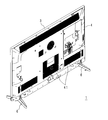
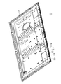
- FIG. 1 is a perspective view of a TV receiver according to Embodiment 1 of the present invention. It is a perspective view which shows the state which looked at TV receiver from the back side. It is a perspective view which shows the state which looked at the display module of TV receiver from the back side.
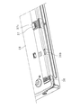
- FIG. 4 is a partially enlarged perspective view showing a lower left part of FIG. 3. It is a rear view which shows a display module.
- FIG. 6 is a partially enlarged rear view showing the lower left part of FIG. 5.
- FIG. 1 is a perspective view of a TV receiver 1 according to Embodiment 1 of the present invention
- FIG. 2 is a perspective view of the TV receiver 1 as seen from the back side
- FIG. 3 shows a display module 2 of the TV receiver 1.
- FIG. 4 is a partially enlarged perspective view showing the lower left portion of FIG. 3
- FIG. 5 is a rear view showing the display module 2
- FIG. 6 is a partially enlarged view showing the lower left portion of FIG.
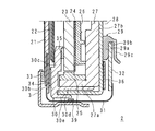
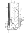
- FIG. 7 is a partial longitudinal sectional view showing the display module 2
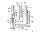
- FIG. 8 is a partial longitudinal sectional view showing a state where the display module 2 is cut at a position different from FIG. 7, and
- FIG. It is a partial longitudinal cross-sectional view which shows the state which stops.
- the TV receiver 1 includes a display module 2 having a display panel 21, a front cabinet 3 made of metal such as aluminum that is accommodated so as to sandwich the display module 2, a rear cabinet 4 made of synthetic resin, and a plurality of speakers. Speaker box 5, two stands 6, a tuner 11 that receives broadcast waves from an antenna (not shown), and a decoder 12 that decodes encoded broadcast waves.
- the display module 2 has a horizontally long and substantially rectangular parallelepiped shape as a whole, and is housed in the front cabinet 3 and the rear cabinet 4 in a vertical posture.
- the materials of the front cabinet 3 and the rear cabinet 4 are not limited to the above.
- the front cabinet 3 has a rectangular frame shape.
- the rear cabinet 4 has a box shape so as to cover the side surface and the back surface of the display module 2.
- the rear cabinet 4 is provided with a plurality of heat radiation slits 41.
- the display module 2 includes a display panel 21, an optical sheet 22, a light guide plate 23, a reflection sheet 24, an LED substrate 25, a light guide plate holder 26, a heat spreader 27, A chassis 28 and a panel chassis 30 are provided.
- planar light is emitted from the light guide plate 23, and the back surface of the display panel 21 is illuminated by the light.
- the chassis 28 has a substantially box shape with the display panel 21 side opened.
- the chassis 28 houses the light guide plate 23, the reflection sheet 24, the LED substrate 25, the light guide plate holder 26, and the heat spreader 27.
- a main board (not shown) including the tuner 11, the decoder 12, and a CPU is provided on the rear surface of the chassis 28.
- the display panel 21 includes a color filter substrate, a liquid crystal layer, a TFT substrate, and a polarizing plate.
- the color filter substrate and the TFT substrate are bonded to each other with a sealing material interposed therebetween, and a liquid crystal layer is sandwiched therebetween.
- the polarizing plate is each arrange
- the light guide plate 23 has a rectangular plate shape, and has a main surface facing the display panel 21, a back surface opposite to the main surface and facing the chassis 28, a pair of long side surfaces, and a pair of short side surfaces.
- the lower long side surface functions as a light incident surface for introducing light into the light guide plate 23, and the light introduced into the light guide plate 23 from the long side surface is displayed from the main surface of the light guide plate 23. The light is emitted toward the panel 21 side.
- the optical sheet 22 is a sheet group including a diffusion sheet, a lens sheet, a DBEF sheet (reflective polarizing sheet), and the like, and is disposed on the main surface side of the light guide plate 23.
- the optical sheet 22 diffuses and collects light emitted from the main surface of the light guide plate 23.
- the LED substrate 25 is for generating light to be introduced into the light guide plate 23, and is disposed on the long side surface side of the light guide plate 23.
- a plurality of LEDs are mounted on the plane of the substrate body of the LED substrate 25.
- the LED substrate 25 extends along the long side surface of the light guide plate 23, and a plurality of LEDs are arranged to face the long side surface of the light guide plate 23.
- the heat spreader 27 includes an LED attachment portion 27 a to which the LED substrate 25 is attached, and a contact portion 27 b that is in contact with the inner surface of the bottom plate of the chassis 28.
- the LED attachment portion 27a and the contact portion 27b are L-shaped in a side view.
- a reflection sheet 24 is disposed on the back surface of the light guide plate 23, and a light guide plate holder 26 is interposed between the heat spreader 27 and the reflection sheet 24.
- the panel chassis 30 includes a display panel support 30b, a light guide plate support 30c, a heat spreader support 30d, a chassis support 30e, and a protrusion 30a.
- the panel chassis 30 has a substantially frame shape, that is, the display panel support portion 30b and the light guide plate support portion 30c, the heat spreader support portion 30d, and the chassis support portion 30e and the projection portion 30a have a substantially L shape in a side view. ing.
- the buffer member 33 is interposed between the peripheral edge portion of the surface of the display panel 21 and the front cabinet 3, and the buffer member 34 is interposed between the peripheral edge portion of the back surface of the display panel 21 and the display panel support portion 30b.
- the display panel 21 is sandwiched between the front cabinet 3 and the display panel support portion 30b.
- the light guide plate support portion 30c is connected to the inside of the display panel support portion 30b, supports the peripheral portion of the surface of the light guide plate 23 with the buffer member 35 interposed on the back side, and the optical sheet 22 on the front side. keeping.
- the heat spreader support portion 30 d supports the LED mounting portion 27 a of the heat spreader 27, and the chassis support portion 30 e supports the side surface of the chassis 28.
- the chassis support part 30e is provided with eight protrusions 30a protruding in the longitudinal direction of the chassis 28 and projecting to the back side of the chassis 28 (see FIG. 8).
- an insulating sheet 36 having a horizontally long rectangular shape is provided along the lower long side portion of the outer surface of the bottom plate of the chassis 28, and the source substrate 32 is provided on the insulating sheet 36.
- the source substrate 32 is provided on the insulating sheet 36.
- eight substrate holding portions 29 are provided in the longitudinal direction of the chassis 28 on the outer surface of the bottom plate of the chassis 28, and each substrate holding portion 29 is a long side portion on the upper side of the source substrate 32. Holding.
- the substrate holding portion 29 is provided on the outer surface of the bottom plate of the chassis 28, is connected to the inner surface abutting portion 29 a that abuts on the inner surface of the source substrate 32, and the inner surface abutting portion 29 a at a right angle, and extends outward to extend to the source substrate 32.
- the substrate holding portion 29 In the upper long side portion of the insulating sheet 36, eight cutouts corresponding to the substrate holding portion 29 are provided.
- the substrate holding portion 29 is provided in the chassis 28, positioning is performed by the notch of the insulating sheet 36, but this positioning does not vary in the left-right direction.
- a plurality of source side terminal portions are provided on the lower long side portion of the TFT substrate, and one end portion of the SOF substrate 31 made of a flexible substrate is connected to each source side terminal portion.
- An IC chip 39 for driving a liquid crystal is mounted on the SOF substrate 31 on a film-like substrate made of a synthetic resin material such as polyimide resin having insulation and flexibility.
- the other end of the SOF substrate 31 is connected to a terminal portion (not shown) provided on the lower long side portion of the source substrate 32.
- the substrate holding part 29 and the protrusions 30a of the panel chassis 30 are arranged in a staggered manner.
- the substrate holding part 29 and the protruding part 30a are in the same position, it becomes difficult to insert and remove the source substrate 32.
- the source substrate 32 is made to take advantage of the bending of the SOF substrate 31. It can be easily detached from the substrate holder 29.
- FIG. 9 is a partial longitudinal sectional view for explaining a method of locking the source substrate 32 to the substrate holding portion 29.
- the SOF substrate 31 since the SOF substrate 31 has flexibility, the inner side contact portion 29a and the outer surface covering portion 29c of the substrate holding portion 29 can be easily used by using the bending to make the upper side portion of the source substrate 32 upper.
- the source substrate 32 can be locked to the substrate holding portion 29 by being inserted therebetween. That is, due to the reaction force of the SOF substrate 31, the source substrate 32 is pushed upward and contacts the side surface covering portion 29b.
- the substrate holding unit 29 is configured to hold the upper long side portion of the source substrate 32, and the lower long side portion of the source substrate 32 is the substrate holding unit 29. Since the fixing is flexible and the degree of bending changes depending on whether the SOF substrate 31 is long or short, the difference in length between the SOF substrates 31 can be absorbed, and the source substrate 32 can be absorbed. Is prevented from breaking.
- the protrusion 30a prevents the source substrate 32 from falling even when the source substrate 32 moves downward due to vibration or the like.
- the IC chip 39 becomes high temperature because it operates at a high frequency. In order to dissipate heat, it is necessary to abut against adjacent metal parts. In the present embodiment, it is in contact with the front cabinet 3 made of aluminum. The IC chip 39 and the front cabinet 3 need to be in close contact with each other for heat dissipation, and the SOF substrate 31 is biased with respect to the front cabinet 3 by utilizing the bending of the SOF substrate 31.
- Fixing the source substrate 32 to the substrate holding portion 29 is easy and can reduce the work man-hours. Since the end portion of the substrate holding portion 29 is inside the side portion of the chassis 28, the end portion of the substrate holding portion is Unlike the fixing structure located outside the side portion, there is no possibility that the substrate holding portion 29 is damaged during manufacturing. Accordingly, there is no occurrence of defects, and the manufacturing cost can be reduced.
- the insulating sheet 36 of the present embodiment can be provided with a plurality of notches corresponding to the above-described substrate holding portion 29 at different positions in the vertical direction.
- the substrate holding part 29 can be provided at an appropriate position.
- the SOF substrate 31 comes into close contact with the front cabinet 3, and the heat of the IC chip 39 is efficiently released to the front cabinet 3. .
- the SOF substrate 31 is not appropriately biased by the front cabinet 3, the SOF substrate 31 is likely to be shaken, and there is a possibility that the SOF substrate 31 is damaged due to vibration and friction caused by the vibration.
- the SOF substrate 31 may be pulled and cut when the SOF substrate 31 or the display panel 21 moves due to vibration, dropping, temperature, or the like.
- FIG. The display module according to the second embodiment of the present invention is different from the display module 2 according to the first embodiment in that the insulating sheet 36 includes a substrate holding portion 37 and a protruding portion 38.
- 10 is a partial perspective view showing the lower left portion of the display module according to Embodiment 2 of the present invention
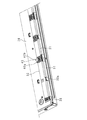
- FIG. 11 is a partial rear view showing the lower left portion of the display module
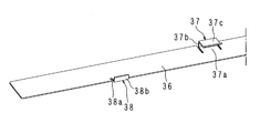
- FIG. 12 is a partial perspective view showing the insulating sheet 36.
- 13 is a partial rear view showing the insulating sheet 36
- FIG. 14 is a partial vertical sectional view showing the display module
- FIG. 15 is a partial vertical sectional view showing a state cut at a position different from FIG.
- the same parts as those in FIGS. 3 to 9 are denoted by the same reference numerals, and detailed description thereof will be omitted.
- the front cabinet 3 is screwed to the lower side surface of the chassis 28 while the end surface is in contact with the panel chassis 30.
- the substrate holding portion 37 is provided at a plurality of locations on the long side portion on the upper side of the insulating sheet 36, with a base portion 37a formed by cutting two portions from the edge portion to the central portion, and connected to the base portion 37a at a right angle, and extends outward.
- a side surface covering portion 37 b that covers the upper long side surface of the source substrate 32 and an outer surface covering portion 37 c that is connected to the side surface covering portion 37 b at a right angle and covers the outer surface of the source substrate 32 are provided.
- the projecting portions 38 are provided at a plurality of locations on the long side portion of the lower side of the insulating sheet 36, and a base portion 38 a formed by cutting two portions from the edge portion to the central portion, and a base portion 38 a, and is provided at right angles. And a side surface covering portion 38b that covers the lower long side surface. The side cover portion 38b prevents the source substrate 32 from moving downward.
- the substrate holding part 37 and the protruding part 38 are arranged in a staggered manner.
- the upper long side portion of the source substrate 32 is configured to be held by the substrate holding portion 37, and the lower long side portion of the source substrate 32 is not locked by the substrate holding portion 37.
- the fixing is flexible, the difference in length between the SOF substrates 31 can be absorbed, and the source substrate 32 is prevented from being disconnected.
- the substrate holding portion 37 and the projections 38 are arranged in a staggered manner, and the source substrate 32 can be easily attached to and detached from the substrate holding portion 37 using the bending of the SOF substrate 31.
- FIG. 16 is a partial perspective view showing the lower left part of the display module according to Embodiment 3 of the present invention
- FIG. 17 is a partial rear view showing the lower left part of the display module
- FIG. 18 is a view of the light guide plate holder 26 from the back side.
- FIG. 19 is a partial vertical sectional view showing the display module.
- the same parts as those in FIGS. 3 to 9 are denoted by the same reference numerals, and detailed description thereof will be omitted.
- the substrate holding part 40 extends outward at the lower part of the light guide plate holder 26 and covers the long side surface on the upper side of the source substrate 32, and is connected to the side surface covering part 40 a at right angles. And an outer surface contact portion 40b that contacts the outer surface.
- the lower long side surface of the source substrate 32 is prevented from moving downward by the protrusions 30a of the panel chassis 30 as in the first embodiment (see FIG. 8).
- the upper long side portion of the source substrate 32 is held by the substrate holding portion 40, and the lower long side portion of the source substrate 32 is not locked to the substrate holding portion 40.
- the fixing is flexible, the difference in length between the SOF substrates 31 can be absorbed, and the source substrate 32 is prevented from being disconnected. Since the substrate holding portion 40 and the protrusions 30a are arranged in a staggered manner, the source substrate 32 can be easily attached to and detached from the substrate holding portion 40 using the bending of the SOF substrate 31.
- FIG. The display module 50 according to Embodiment 4 of the present invention is a direct type display module.
- 20 is a partial longitudinal sectional view showing the display module 50
- FIG. 21 is a perspective view showing the diffusion plate holder 54
- FIG. 22 is a perspective view showing a part of the chassis 28 before the source substrate 32 is attached
- FIG. It is a perspective view which shows a part of chassis 28 after attaching the board
- the display module 50 includes a display panel 21, an optical sheet 22, a diffusion plate 51, a reflection sheet 24, an LED substrate (not shown), a diffusion plate holder 54, a chassis 28, and a panel chassis 30.
- planar light is emitted from the diffusion plate 51, and the back surface of the display panel 21 is illuminated by the light.
- the chassis 28 has, for example, a box shape formed by molding a metal plate, a rectangular flat plate portion 28a, a side portion 28b provided so as to project obliquely outward from the peripheral edge of the flat plate portion 28a, and a side portion 28b.
- the edge portion 28c is provided so as to project outward from the end edge portion of the flat plate portion 28a substantially in parallel with the flat plate portion 28a, and the covering portion 28d is provided at a right angle to the edge portion 28c and covers the diffusion plate 51.
- rectangular locking holes 28e and 28e are provided near both ends in the longitudinal direction of the edge portion 28c.
- the reflection sheet 24 is in contact with the inner surface of the chassis 28.
- the reflection sheet 24 has a rectangular flat plate portion, an inclined portion that rises from the periphery of the flat plate portion, and an edge portion that protrudes from the edge of the inclined portion.
- the diffusion plate 51 has a rectangular plate shape, and has a main surface facing the display panel 21 side, a back surface opposite to the main surface and facing the chassis 28, a pair of long side surfaces, and a pair of short side surfaces. Light incident from the back surface is scattered and diffused and emitted toward the display panel 21 side.
- the diffusion plate holder 54 has an elongated plate shape, and two sets of substrate support portions 54a and locking portions 54c are provided near both ends.
- the locking portion 54c is provided at the upper edge portion of the diffusion plate holder 54 at a right angle to the plane of the diffusion plate holder 54, and the substrate support portion 54a is provided so as to extend obliquely downward from the upper edge portion.
- a plate locking portion 54b having a triangular shape in a side view is provided at the distal end portion of the substrate support portion 54a.
- the optical sheet 22 is a sheet group including a diffusion sheet, a lens sheet, a DBEF sheet (reflection type polarizing sheet), and the like, and is disposed on the main surface side of the diffusion plate 51.
- the optical sheet 22 diffuses and collects light emitted from the main surface of the diffusion plate 51.
- the panel chassis 30 includes a display panel support part 30b, a side part support part 30f, and a diffusion plate holding part 30g.
- the panel chassis 30 has a substantially frame shape, that is, the display panel support portion 30b, the diffusion plate sandwiching portion 30g, and the side portion 30f are substantially L-shaped in a side view.
- the diffusion plate holding portion 30g is connected to the upper inner side of the display panel support portion 30b, supports the peripheral portion of the surface of the diffusion plate 51 with the buffer member 35 interposed on the back side, and the optical sheet 22 on the front side. Holding.
- the side part 30 f supports the side part of the diffusion plate 51.
- the locking portion 54c of the substrate holding portion 54 is locked to the upper edge portion of the locking hole 28e of the chassis 28, the substrate support portion 54b is protruded from the locking hole 28e, and the end portion of the reflection sheet 24 is provided on the front side.
- the diffusion plate holder 54 holds the end portion of the diffusion plate 51.
- a buffer member (not shown) is interposed between the peripheral portion of the surface of the display panel 21 and the front cabinet 3, and the buffer member 34 is interposed between the peripheral portion of the back surface of the display panel 21 and the display panel support portion 30b.
- the display panel 21 is sandwiched between the front cabinet 3 and the display panel support 30b.
- an insulating sheet 53 is provided on the lower portion of the side portion 28b of the chassis 28.
- the insulating sheet 53 has a long and narrow plate shape, and is provided with notches 53a and 53a near both ends in the longitudinal direction of the upper edge, and rectangular holes 53b and 53b are provided on the inner side and the lower side of the notches 53a and 53a. Is provided. That is, the notch 53 a and the locking hole 28 e are arranged in a state shifted in the longitudinal direction of the insulating sheet 53.
- the substrate holding portion 52 includes an inner surface abutting portion 52a that abuts on the inner surface of the source substrate 32, a side surface covering portion 52b that is connected to the inner surface abutting portion 52a at a right angle, extends outward, and covers the side surface of the source substrate 32. And an outer surface abutting portion 52c that is provided at a right angle to the side surface covering portion 52b and abuts against the outer surface of the source substrate 32.
- a plurality of source side terminal portions are provided on the lower long side portion of the TFT substrate of the display panel 21, and each source side terminal portion has one end of an SOF substrate 31 made of a flexible substrate. Are connected.
- An IC chip 39 for driving a liquid crystal is mounted on the SOF substrate 31 on a film-like substrate made of a synthetic resin material such as polyimide resin having insulation and flexibility.
- the other end of the SOF substrate 31 is connected to a terminal portion (not shown) provided on the lower long side portion of the source substrate 32.
- the SOF substrate 31 has flexibility, the upper long side portion of the source substrate 32 can be easily inserted between the inner surface abutting portion 52a and the outer surface abutting portion 52c of the substrate holding portion 52 using bending. Thus, the source substrate 32 can be locked to the substrate holding portion 52. That is, the source substrate 32 is pushed upward by the reaction force of the SOF substrate 31, and the upper long side portion is held between the substrate holding portions 52.
- the source substrate 32 is supported by the notch 53a and the substrate support portion 54b protruding from the locking holes 28e arranged in a staggered manner. Since it is restrained by 54b, the source substrate 32 can be favorably fixed to the side portion 28b.
- the IC chip 39 needs to be brought into contact with an adjacent metal portion for heat dissipation. In the present embodiment, it is in contact with the front cabinet 3 made of aluminum.
- the SOF substrate 31 is biased with respect to the front cabinet 3 by utilizing the bending of the SOF substrate 31.
- the shape of the side portion 28b of the chassis 28 (the inclination angle of the side portion of the display portion holding body, the length of the side portion, etc.) Regardless, the source substrate 31 can be fixed to the chassis 28.
- FIG. The display module 55 according to Embodiment 5 of the present invention is a direct type display module.
- FIG. 24 is a partial longitudinal sectional view showing the display module 55
- FIG. 25 is a partial back view showing the display module 55.
- the source substrate 32 according to the present embodiment has a smaller vertical dimension than the source substrate 32 according to the fourth embodiment.
- the insulating sheet 53 has the notch 53a and the hole 53b.
- the insulating sheet 53 is positioned by the hole 53b and the substrate holding part 52 is provided on the side part 28b of the chassis 28. It has been.
- the source substrate 32 according to the present embodiment also uses the flexure of the SOF substrate 31 so that the long side portion on the upper side of the source substrate 32 can be easily mounted on the substrate holding portion.
- the source substrate 32 can be locked to the substrate holding portion 52 by being inserted between the inner surface abutting portion 52 a and the outer surface abutting portion 52 c. That is, the source substrate 32 is pushed upward by the reaction force of the SOF substrate 31, and the upper long side portion is held between the substrate holding portions 52.
- the source substrate 32 is supported by the notch 53a and the substrate support portion 54b protruding from the locking holes 28e arranged in a staggered manner. Since it is restrained by 54b, the source substrate 32 can be satisfactorily fixed to the side portion 28b.
- the substrate holding portion 52 is selected.
- the source substrate 31 can be fixed to the chassis 28 only by changing the position. That is, by providing a plurality of positioning portions such as notches 53 a according to the vertical dimension of the source substrate 31, the chassis 28 and the insulating sheet 53 are shared, and the source substrates 31 having different vertical dimensions are fixed to the chassis 28. can do. Accordingly, there is no need to provide a plurality of marking lines on the chassis 28, and no sticking mistakes occur. There is no need to remodel the mold of the chassis 28 in order to provide a new marking line, and a new positioning portion may be provided in the insulating sheet 53.
- the following effects are also generated as in the first embodiment.
- the SOF substrate 31 is moderately slackened and the source substrate 32 is inserted into the substrate holding part 52 in this state, the outer surface of the SOF substrate 31 is brought into close contact with the inner surface of the front cabinet 3 by the elasticity of the SOF substrate 31. Then, the IC chip 39 arranged at the substantially central portion of the SOF substrate 31 comes into close contact with the front cabinet 3, and the heat of the IC chip 39 is efficiently released to the front cabinet 3.
- the SOF substrate 31 is not appropriately biased by the front cabinet 3, the SOF substrate 31 is likely to be shaken, and there is a possibility that the SOF substrate 31 is damaged due to vibration and friction caused by the vibration.
- the SOF substrate 31 may be pulled and cut when the SOF substrate 31 or the display panel 21 moves due to vibration, dropping, temperature, or the like.
- the display device (1, 50, 55) has a display unit (2) having a display panel (21) for displaying an image, a box shape, and a part of the display unit.
- a display unit holding body (28) that accommodates and holds the display unit in a state of protruding from the opening, and has a horizontally long rectangular shape with one long side portion of the outer surface of the bottom plate facing the opening of the display unit holding unit
- the display device including a drive substrate (32) that is arranged along one side portion and drives the display panel, the display unit holding body holds a part of the other long side portion of the drive substrate. Part (29, 52).
- the fixing is flexible and the substrate such as a flexible substrate that connects the drive substrate and the display portion.
- the length of the wiring can be absorbed, that is, the degree of bending is changed between the case where the wiring is long and the case where the wiring is short, so that the disconnection of the substrate or the wiring is suppressed.
- Fixing the drive substrate to the substrate holding portion is easy, and the number of work steps can be reduced.
- substrate holding part exists inside the side part of a holding body, there is no possibility that a board
- the drive substrate can be fixed to the chassis regardless of the shape of the display unit holder (the inclination angle of the side portion of the display unit holder, the length of the side portion, etc.), and the substrate holder is shared. be able to.
- the display device (1) includes a panel holding body (30) that holds the display panel, and the panel holding body supports a side surface of the display section holding body and is on the side of the driving substrate. It is characterized by including a protrusion (30a) projecting toward the top.
- the display device (50, 55) includes a substrate support portion (54a) that supports a part of the one long side portion of the drive substrate.
- the drive substrate can be supported, and the drive substrate can be fixed to the display unit holder.
- a display device (50, 55) includes a light source, a diffusion plate (51) for diffusing light emitted from the light source, and a diffusion plate support (supporting the diffusion plate in the display unit holder). 54), and the diffusion plate support includes the substrate support.
- a substrate support portion is provided on the diffusion plate support that supports the edge of the diffusion plate, and the substrate support portion is provided so as to slightly protrude from the diffusion plate support.
- the drive substrate can be easily supported.
- the display device (1, 50, 55) includes an insulating sheet (53) interposed between the display unit holder and the driving substrate, and the insulating sheet positions the substrate holding unit. It has the positioning part (53a, 53b) for doing.
- the substrate holding part can be provided by the positioning part after the insulating sheet is arranged on the display part holding body without providing the marking line on the display part holding body.
- the display device (1, 50, 55) according to the present invention is characterized in that the insulating sheet includes a plurality of positioning portions having different vertical positions.
- the substrate holding part is provided on the display part holding body
- a plurality of marking lines are provided on the common display part holding body, and there is a possibility that a sticking error may occur.
- a plurality of positioning portions are provided in accordance with the vertical dimension of the drive substrate, so that the display unit holder and the insulating sheet are shared, and the drive substrates having different vertical dimensions are fixed to the display unit holder. be able to. Therefore, there is no need to provide a plurality of marking lines on the display unit holder, and no sticking mistakes occur.
- the display device (1, 50, 55) further includes a front cabinet (3) that covers a peripheral portion of the display unit, and a flexible substrate (31) that connects the display unit and the drive substrate, The flexible substrate is configured to be able to contact an inner surface of the front cabinet.
- the following effects are produced by appropriately determining the position of the substrate holding portion.
- the driving substrate is inserted into the substrate holding portion (29, 52), and the outer surface of the flexible substrate covers the peripheral portion of the display portion by the elasticity of the flexible substrate. Adheres to the inner surface of the front cabinet. Then, the IC chip disposed on the flexible substrate comes into close contact with the front cabinet, and the heat of the IC chip can be efficiently radiated to the front cabinet.
- the flexible substrate is not appropriately biased to the front cabinet, the flexible substrate is likely to shake, and the flexible substrate may be damaged due to vibration and friction caused by the vibration.
- the flexible substrate may be pulled and cut when the flexible substrate and the display panel move due to vibration, dropping, temperature, or the like.
- the display device (1) includes a display unit (2) for displaying an image and a box shape, and holds and holds the display unit in a state in which a part of the display unit protrudes from the opening.
- the upper long side portion of the drive substrate is held by the substrate holding portion and the lower long side portion of the lower side of the drive substrate is not locked, so that the fixing is flexible, and the drive substrate and the display portion It is possible to absorb the length of the substrate or wiring connecting the two, and the substrate or wiring is prevented from being disconnected. Fixing the drive substrate to the substrate holding portion is easy, and the number of work steps can be reduced. Moreover, since the edge part of a board
- the display device according to the present invention is characterized in that the insulating sheet has a protrusion (38) provided on the one long side portion and protruding toward the drive substrate.
- a display device (1) includes a display panel (21) that displays an image, a light guide plate (23) that has a rectangular flat plate shape, emits light to the display panel, and irradiates the display panel.
- a light source (25) that makes light incident on a side surface or a flat surface of the light guide plate, a light source holder (28) that has a box shape and contains and holds the light guide plate and the light source, and the light guide plate as the light source.
- a light guide plate support (26) supported in the holding body, and having a horizontally long rectangular shape, with one long side portion arranged along one side portion of the outer surface of the bottom plate facing the opening of the light source holding body;
- the light guide plate support includes a substrate holding portion (40) for holding a part of the other long side portion of the driving substrate. .
- the upper long side portion of the drive substrate is held by the substrate holding portion and the lower long side portion of the lower side of the drive substrate is not locked, so that the fixing is flexible, and the drive substrate and the display portion It is possible to absorb the length of the substrate or wiring connecting the two, and the substrate or wiring is prevented from being disconnected. Fixing the drive substrate to the substrate holding portion is easy, and the number of work steps can be reduced. Moreover, since the edge part of a board
- a TV receiver (1) includes any one of the display devices described above and a receiving unit that receives a television broadcast, and the display device is based on the television broadcast received by the receiving unit. An image is displayed on the screen.
- the present invention it is easy to fix the drive substrate, there is no possibility of damaging the substrate holding part at the time of manufacture, the workability man-hours can be reduced, and the product can be easily manufactured without causing defective products.
- the present invention is not limited to the contents of the above-described embodiments, and various modifications can be made within the scope of the claims. In other words, embodiments obtained by combining technical means appropriately modified within the scope of the claims are also included in the technical scope of the present invention.
- the present invention is not limited to this. It is also possible to apply a gate substrate as the driving substrate.
Landscapes
- Physics & Mathematics (AREA)
- Nonlinear Science (AREA)
- General Physics & Mathematics (AREA)
- Engineering & Computer Science (AREA)
- Signal Processing (AREA)
- Multimedia (AREA)
- Theoretical Computer Science (AREA)
- Mathematical Physics (AREA)
- Chemical & Material Sciences (AREA)
- Crystallography & Structural Chemistry (AREA)
- Optics & Photonics (AREA)
- Devices For Indicating Variable Information By Combining Individual Elements (AREA)
- Liquid Crystal (AREA)
Abstract
駆動基板の表示部保持体への固定が容易であり、かつ柔軟性を有し、駆動基板と表示部とを接続するフレキシブル基板等の基板又は配線の断線が抑制され、固定部分が破損する虞もなく、製造コストを減じることができる表示装置及び、該表示装置を備えるテレビジョン受信機を提供することを目的とする。 表示モジュール(2)は、映像を表示する表示パネル(21)と、箱状をなし、表示パネル(21)が開口から突出した状態で表示モジュール(2)を収容して保持するシャーシ(28)と、シャーシ(28)の底板の外面の一辺部分に沿うように配され、表示パネル(21)を駆動するソース基板(32)とを備える。シャーシ(28)は、ソース基板(32)の他長辺部分の一部を保持する基板保持部(29)を備える。
Description
本発明は、映像を表示する表示部、該表示部を保持する保持体を備える表示装置、並びに該表示装置を備えるテレビジョン受信機に関する。
例えば液晶テレビジョン受信機等のテレビジョン受信機(以下、TV受信機という)は、前側で映像を表示する表示パネル、及び表示パネルに光を照射するバックライトを有する表示モジュール(表示部)と、表示モジュールを挟むようにして収容する合成樹脂製のフロントキャビネット及びリアキャビネットと、スタンドとを備える。表示モジュールは、全体として横長の略直方体状をなし、縦姿勢でフロントキャビネット及びリアキャビネットに収容されている。
バックライトにはエッジ型(サイドライト方式、導光板方式)と直下型とがある。
エッジ型のバックライトを有する液晶表示装置として、薄型化、軽量化、狭額縁化を実現するために、矩形箱状のシャーシ[BL(バックライト)シャーシ]に、導光板、光学シート、及びLED(Light Emitting Diode)基板を収納してなるバックライトユニットを液晶表示パネル(以下、表示パネルという)の背面に配した表示モジュールをフレームで覆ったものが挙げられる。LED基板は、細長い基板の平面に、複数のLEDを実装してなる。バックライトユニットが片側のエッジライト型である場合、LED基板は、矩形板状の導光板の一方の長側面に配される。LEDから発光し、導光板の長側面に入射した光は導光板の主面から出射して、液晶表示パネルの背面を照射する。なお、LED基板は導光板の短側面に配することにしてもよい。
エッジ型のバックライトを有する液晶表示装置として、薄型化、軽量化、狭額縁化を実現するために、矩形箱状のシャーシ[BL(バックライト)シャーシ]に、導光板、光学シート、及びLED(Light Emitting Diode)基板を収納してなるバックライトユニットを液晶表示パネル(以下、表示パネルという)の背面に配した表示モジュールをフレームで覆ったものが挙げられる。LED基板は、細長い基板の平面に、複数のLEDを実装してなる。バックライトユニットが片側のエッジライト型である場合、LED基板は、矩形板状の導光板の一方の長側面に配される。LEDから発光し、導光板の長側面に入射した光は導光板の主面から出射して、液晶表示パネルの背面を照射する。なお、LED基板は導光板の短側面に配することにしてもよい。
直下型のバックライトの場合、シャーシは、矩形状をなす平板部、平板部の周縁に立設された側部、及び側部の端部から平板部と略平行な状態で外側に張り出すように設けられた縁部とを有する。シャーシの内面には、反射シートが当接される。平板部には、複数のLED基板がLEDのレンズ部が反射シートから突出する状態で、平板部の短手方向に並設されている。縁部には、LED基板から照射された光を拡散する拡散板が載置されている。
表示モジュールは投資金額が大きいため、コストダウンを図るために、近年、種々のTV受信機において同一のシャーシを使用することが多くなっている。
図26は従来のエッジ型の表示モジュールを裏側から見た状態を示す斜視図、図27は該表示モジュールの一部縦断面図である。
この表示モジュールは、表示パネル21と、光学シート22と、導光板23と、反射シート24と、LED基板25と、導光板ホルダ26と、ヒートスプレッダ27と、シャーシ28と、パネルシャーシ30とを備える。
この表示モジュールは、表示パネル21と、光学シート22と、導光板23と、反射シート24と、LED基板25と、導光板ホルダ26と、ヒートスプレッダ27と、シャーシ28と、パネルシャーシ30とを備える。
シャーシ28は、表示パネル21側が開口された略箱状をなす。そして、シャーシ28に、導光板23、反射シート24、LED基板25、導光板ホルダ26、及びヒートスプレッダ27が収納されている。
パネルシャーシ30は枠状をなす。表示パネル21の表面の周縁部とフロントキャビネット3との間に緩衝部材33が介在し、表示パネル21の裏面の周縁部とパネルシャーシ30の正面側部分との間に緩衝部材34が介在する状態で、表示パネル21はフロントキャビネット3及びパネルシャーシ30に挟持されている。
パネルシャーシ30の側面側部分はシャーシ28の側面を支持している。
以上の構成により、表示パネル21とバックライトとが一体化されている。
LED基板25から発光した光は、導光板23の長側面から入射し、主面から出射して、表示パネル21の背面が照射される。
パネルシャーシ30の側面側部分はシャーシ28の側面を支持している。
以上の構成により、表示パネル21とバックライトとが一体化されている。
LED基板25から発光した光は、導光板23の長側面から入射し、主面から出射して、表示パネル21の背面が照射される。
この表示モジュールにおいては、シャーシ28の底板の外面の下側の長辺部分に沿って、横長の矩形状をなす絶縁シート36が設けられており、絶縁シート36上にソース基板32が配されている。
ソース基板32は、長手方向の複数箇所において、基板保持部41により保持されている。
基板保持部41は絶縁シート36に設けられており、ソース基板32の内面に当接される内面当接部41aと、ソース基板32の外面を被覆する外面被覆部41bと、内面当接部41aの下端部に設けられ、外側に突出した突出部41dと、外面被覆部41bの下端部に設けられ、突出部41dに係止される係止部41cとを備える。
ソース基板32は、長手方向の複数箇所において、基板保持部41により保持されている。
基板保持部41は絶縁シート36に設けられており、ソース基板32の内面に当接される内面当接部41aと、ソース基板32の外面を被覆する外面被覆部41bと、内面当接部41aの下端部に設けられ、外側に突出した突出部41dと、外面被覆部41bの下端部に設けられ、突出部41dに係止される係止部41cとを備える。
表示パネル21の下側の長辺部分には、複数のソース側端子部(不図示)が設けられ、各ソース側端子部にはそれぞれ、フレキシブル基板からなるSOF(System On Film)基板31の一方の端部が接続されている。SOF基板31の他方の端部はソース基板32の下側の長辺部分に接続されている。
シャーシ28の共用化によって、このソース基板32の固定に弊害が生じている。
シャーシ28の共用化によって、このソース基板32の固定に弊害が生じている。
ソース基板32をシャーシ28に固定する場合、図27に示すように、ソース基板32の下側の長側面を突出部41dに載置した上で、係止部41cを突出部41dに係止する。基板保持部41は絶縁シート36に設けた後、閉じてあり、ソース基板32の固定時に開けてソース基板32の前記長側面を突出部41dに載置し、再度閉じることになるので、固定の作業は煩雑である。
そして、この構成によれば、基板保持部41の絶縁シート36への貼り付けの精度がソース基板32の固定の作業性に影響する。すなわち、基板保持部41が設計より上側に貼り付けられていた場合、又は左右にずれていた場合、SOF基板31の短手方向の長さに余裕がないとソース基板32を固定することができない。
そして、この構成によれば、基板保持部41の絶縁シート36への貼り付けの精度がソース基板32の固定の作業性に影響する。すなわち、基板保持部41が設計より上側に貼り付けられていた場合、又は左右にずれていた場合、SOF基板31の短手方向の長さに余裕がないとソース基板32を固定することができない。
そして、薄型の表示モジュールに使用することを考えてSOF基板31の短手方向の長さを最適化した場合に、シャーシ28を少し厚みが厚い表示モジュールに適用する場合、SOF基板31の長さが短いため、上述の固定方法ではソース基板32を基板保持部41に挿入する際にSOF基板31を引っ張って断線する虞があるという問題があった。
また、表示モジュールの厚みに対して、ソース基板32の長さが長すぎる場合、ソース基板32が上側にずれ、固定できないことがあるという問題があった。
また、表示モジュールの厚みに対して、ソース基板32の長さが長すぎる場合、ソース基板32が上側にずれ、固定できないことがあるという問題があった。
表示モジュールが厚い場合、又はSOF基板31の長さが短い場合に従来の方法で固定するとき、基板保持部41を、端部がシャーシ28の側面の外側に位置するように配する必要がある。
図28は、基板保持部41の係止部41cがシャーシ28の側面の外側に端部に位置する場合を示す一部縦断面図である。
この場合、製造時に、係止部41cが他部品と接触して基板保持部41が破損する虞がある。
図28は、基板保持部41の係止部41cがシャーシ28の側面の外側に端部に位置する場合を示す一部縦断面図である。
この場合、製造時に、係止部41cが他部品と接触して基板保持部41が破損する虞がある。
特許文献1には、表示モジュールの表示パネルの端縁にフレキシブル基板を介して接続された駆動基板を、表示モジュールのリアフレームの背面側へ引き出し、板状をなすホルダの凹部に遊嵌した上で、該ホルダをリアフレームの背面にネジ止めした、駆動基板の固定構造が示されている。
この構造の場合、駆動基板が前記凹部に遊嵌されているので、フレキシブル基板に係るテンション等の負荷が緩和され、フレキシブル基板の断線が防止され得る。しかし、凹部の遊びによる前記負荷の緩和吸収には限度があり、しかも、この構成によれば、駆動基板の両長辺を係止するので、固定に柔軟性がなく、依然としてフレキシブル基板の断線の虞があるという問題があった。
この構造の場合、駆動基板が前記凹部に遊嵌されているので、フレキシブル基板に係るテンション等の負荷が緩和され、フレキシブル基板の断線が防止され得る。しかし、凹部の遊びによる前記負荷の緩和吸収には限度があり、しかも、この構成によれば、駆動基板の両長辺を係止するので、固定に柔軟性がなく、依然としてフレキシブル基板の断線の虞があるという問題があった。
また、直下型の表示モジュールにおいて、シャーシの側部が傾斜している場合、該側部に沿わせてソース基板を配することになるが、側部に上述の基板保持部41を備え、該基板保持部41にソース基板を固定することにしたとき、SOF基板の縦寸法が短いと、ソース基板を基板保持部41により固定することができないという問題があった。従って、シャーシの側部の形状に対応して、専用の基板保持部を備える必要があった。
そして、共通のシャーシを用い、異なる表示パネルを搭載することで金型費用の削減を図る場合、表示パネルによってソース基板の縦寸法が異なるので、表示パネル毎に専用の基板保持部が必要になるという問題があった。
すなわち、シャーシの形状、又は駆動基板の縦寸法に依らず、駆動基板をシャーシに固定することができる構造が求められていた。
そして、共通のシャーシを用い、異なる表示パネルを搭載することで金型費用の削減を図る場合、表示パネルによってソース基板の縦寸法が異なるので、表示パネル毎に専用の基板保持部が必要になるという問題があった。
すなわち、シャーシの形状、又は駆動基板の縦寸法に依らず、駆動基板をシャーシに固定することができる構造が求められていた。
本発明は斯かる事情に鑑みてなされたものであり、駆動基板の表示部保持体への固定が容易であり、かつ柔軟性を有し、駆動基板と表示部とを接続するフレキシブル基板等の基板又は配線の断線が抑制され、固定部分が破損する虞もなく、製造コストを減じることができる表示装置及び、該表示装置を備えるTV受信機を提供することを目的とする。
そして、表示部保持体の形状、又は駆動基板の縦寸法に依らず、駆動基板を表示部保持体に固定することができる表示装置及び、該表示装置を備えるTV受信機を提供することを目的とする。
そして、表示部保持体の形状、又は駆動基板の縦寸法に依らず、駆動基板を表示部保持体に固定することができる表示装置及び、該表示装置を備えるTV受信機を提供することを目的とする。
本発明に係る表示装置は、映像を表示する表示パネルを有する表示部と、箱状をなし、該表示部の一部が開口から突出した状態で該表示部を収容して保持する表示部保持体と、横長の矩形状をなし、一長辺部分を前記表示部保持体の開口に対向する底板の外面の一辺部分に沿うように配され、前記表示パネルを駆動する駆動基板とを備える表示装置において、前記表示部保持体は、前記駆動基板の他長辺部分の一部を保持する基板保持部を備えることを特徴とする。
本発明に係る表示装置は、前記表示パネルを保持するパネル保持体を備えており、前記パネル保持体は、前記表示部保持体の側面を支持し、かつ前記駆動基板側へ突出した突起部を備えることを特徴とする。
本発明に係る表示装置は、前記駆動基板の前記一長辺部分の一部を支持する基板支持部を備えることを特徴とする。
本発明に係る表示装置は、光源と、該光源から照射された光を拡散する拡散板と、該拡散板を前記表示部保持体内で支持する拡散板支持体とを備え、前記拡散板支持体は、前記基板支持部を備えることを特徴とする。
本発明に係る表示装置は、前記表示部保持体と前記駆動基板との間に介在される絶縁シートを備え、該絶縁シートは、前記基板保持部を位置決めするための位置決め部を備えることを特徴とする。
本発明に係る表示装置は、前記絶縁シートは、縦方向の位置が異なる複数の位置決め部を備えることを特徴とする。
本発明に係る表示装置は、前記表示部の周縁部を覆う前キャビネットと、前記表示部及び前記駆動基板を接続するフレキシブル基板とをさらに備え、前記フレキシブル基板は、前記前キャビネットの内面に当接可能に構成されていることを特徴とする。
本発明に係る表示装置は、映像を表示する表示部と、箱状をなし、該表示部の一部が開口から突出した状態で該表示部を収容して保持する保持体と、横長の矩形状をなし、一長辺部分が前記保持体の開口に対向する底面の外面の一辺部分に沿うように設けられた絶縁シートと、該絶縁シート上に設けられ、前記表示部を駆動する駆動基板とを備える表示装置において、前記絶縁シートは、前記駆動基板の他長辺部分の一部を保持する基板保持部を備えることを特徴とする。
本発明に係る表示装置は、映像を表示する表示パネルと、矩形平板状をなし、光を前記表示パネルへ出射して該表示パネルを照射する導光板と、前記導光板の側面又は平面へ光を入射させる光源と、箱状をなし、前記導光板、及び前記光源を収容して保持する光源保持体と、前記導光板を前記光源保持体内で支持する導光板支持体と、横長の矩形状をなし、一長辺部分が前記光源保持体の開口に対向する底板の外面の一辺部分に沿うように配され、前記表示パネルを駆動する駆動基板とを備える表示装置において、前記導光板支持体は、前記駆動基板の他長辺部分の一部を保持する基板保持部を備えることを特徴とする。
本発明に係るテレビジョン受信機は、上述のいずれかの表示装置と、テレビジョン放送を受信する受信部とを備え、前記受信部にて受信したテレビジョン放送に基づいて、前記表示装置に映像を表示するようにしてあることを特徴とする。
本発明の表示装置によれば、基板保持部により駆動基板の一方の長辺部分が保持されるように構成されており、駆動基板の他方の長辺部分は係止されないので、固定が柔軟性を有し、駆動基板と表示部とを接続するフレキシブル基板等の基板又は配線の長短が吸収され得、すなわち長い場合と短い場合とで撓みの度合が変わることで、該基板又は配線が断線するのが抑制されている。
そして、表示部保持体の形状(表示部保持体の側部の傾斜角度、及び側部の長さ等)に依らず、駆動基板を表示部保持体に固定することができ、基板保持部を共通化させることができる。
駆動基板の基板保持部への固定は容易であり、作業工数を減じることができる。また、基板保持部は保持体の側部の内側に設けられているので、基板保持部の端部が前記側部の外側に位置する固定構造のように、製造時に基板保持部が破損する虞はない。従って、製造コストを減じることができる。
そして、表示部保持体の形状(表示部保持体の側部の傾斜角度、及び側部の長さ等)に依らず、駆動基板を表示部保持体に固定することができ、基板保持部を共通化させることができる。
駆動基板の基板保持部への固定は容易であり、作業工数を減じることができる。また、基板保持部は保持体の側部の内側に設けられているので、基板保持部の端部が前記側部の外側に位置する固定構造のように、製造時に基板保持部が破損する虞はない。従って、製造コストを減じることができる。
以下、本発明をその実施の形態を示す図面に基づいて具体的に説明する。
実施の形態1.
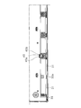
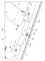
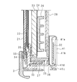
図1は本発明の実施の形態1に係るTV受信機1の斜視図、図2はTV受信機1を裏側から見た状態を示す斜視図、図3はTV受信機1の表示モジュール2を裏側から見た状態を示す斜視図、図4は図3の左下部分を示す一部拡大斜視図、図5は表示モジュール2を示す背面図、図6は図5の左下部分を示す一部拡大背面図、図7は表示モジュール2を示す一部縦断面図、図8は図7と異なる位置で切断した状態を示す一部縦断面図、図9はソース基板32を基板保持部29に係止する状態を示す一部縦断面図である。
実施の形態1.
図1は本発明の実施の形態1に係るTV受信機1の斜視図、図2はTV受信機1を裏側から見た状態を示す斜視図、図3はTV受信機1の表示モジュール2を裏側から見た状態を示す斜視図、図4は図3の左下部分を示す一部拡大斜視図、図5は表示モジュール2を示す背面図、図6は図5の左下部分を示す一部拡大背面図、図7は表示モジュール2を示す一部縦断面図、図8は図7と異なる位置で切断した状態を示す一部縦断面図、図9はソース基板32を基板保持部29に係止する状態を示す一部縦断面図である。
TV受信機1は、表示パネル21を有する表示モジュール2と、該表示モジュール2を挟むようにして収容するアルミニウム等の金属製のフロントキャビネット3、及び合成樹脂製のリアキャビネット4と、複数のスピーカを内蔵したスピーカボックス5と、2つのスタンド6と、アンテナ(不図示)から放送波を受信するチューナ11と、符号化された放送波を復号するデコーダ12とを備える。表示モジュール2は、全体として横長の略直方体状をなし、縦姿勢でフロントキャビネット3及びリアキャビネット4内に収容されている。フロントキャビネット3及びリアキャビネット4の材質は上記のものに限定されない。
フロントキャビネット3は、矩形枠状をなす。
リアキャビネット4は、表示モジュール2の側面及び背面を覆うように箱状をなしている。リアキャビネット4には、複数の放熱スリット41が設けられている。
リアキャビネット4は、表示モジュール2の側面及び背面を覆うように箱状をなしている。リアキャビネット4には、複数の放熱スリット41が設けられている。
図7及び図8に示すように、表示モジュール2は、表示パネル21と、光学シート22と、導光板23と、反射シート24と、LED基板25と、導光板ホルダ26と、ヒートスプレッダ27と、シャーシ28と、パネルシャーシ30とを備える。
表示動作の際には、導光板23から面状の光が出射され、その光によって表示パネル21の背面が照明される。
表示動作の際には、導光板23から面状の光が出射され、その光によって表示パネル21の背面が照明される。
シャーシ28は、表示パネル21側が開口された略箱状をなす。そして、シャーシ28に、導光板23、反射シート24、LED基板25、導光板ホルダ26、及びヒートスプレッダ27が収納されている。
シャーシ28の裏面には、前記チューナ11、及びデコーダ12、及びCPU等を備えるメイン基板(不図示)が設けられている。
シャーシ28の裏面には、前記チューナ11、及びデコーダ12、及びCPU等を備えるメイン基板(不図示)が設けられている。
表示パネル21は、カラーフィルタ基板と、液晶層と、TFT基板と、偏光板とを有する。カラーフィルタ基板とTFT基板とはシール材を挟んで互いに貼り合わされており、その間に液晶層が挟持されている。そして、偏光板は、カラーフィルタ基板及びTFT基板の液晶層側とは反対側の面上にそれぞれ配されている。
導光板23は矩形板状をなし、表示パネル21側に対向する主面と、主面の反対面でシャーシ28に対向する裏面と、一対の長側面と、一対の短側面とを有する。そして、下側の長側面が、導光板23内に光を導入するための光入射面として機能し、該長側面から導光板23内へ導入された光は、導光板23の主面から表示パネル21側に向かって出射する。
光学シート22は、拡散シート、レンズシート及びDBEFシート(反射型偏光シート)等を含むシート群であり、導光板23の主面側に配されている。そして、この光学シート22によって、導光板23の主面から出射された光の拡散及び集光等が行われる。
LED基板25は、導光板23内へ導入する光を生成するためのものであり、導光板23の前記長側面側に配されている。LED基板25の基板本体の平面に、複数のLEDが実装されている。LED基板25は、導光板23の前記長側面に沿って延び、複数のLEDが導光板23の長側面と対向するように配される。
ヒートスプレッダ27は、LED基板25が取り付けられるLED取付部27aと、シャーシ28の底板の内面に当接される当接部27bとを備える。LED取付部27aと当接部27bとは、側面視でL字状をなしている。
導光板23の前記裏面には反射シート24が配され、ヒートスプレッダ27と反射シート24との間には、導光板ホルダ26が介在されている。
導光板23の前記裏面には反射シート24が配され、ヒートスプレッダ27と反射シート24との間には、導光板ホルダ26が介在されている。
パネルシャーシ30は、表示パネル支持部30b、導光板支持部30c、ヒートスプレッダ支持部30d、シャーシ支持部30e、及び突起部30aを備える。パネルシャーシ30は略枠状をなし、すなわち表示パネル支持部30b及び導光板支持部30cと、ヒートスプレッダ支持部30d、並びにシャーシ支持部30e及び突起部30aとが、側面視で略L字状をなしている。
表示パネル21の表面の周縁部とフロントキャビネット3との間に緩衝部材33が介在し、表示パネル21の裏面の周縁部と表示パネル支持部30bとの間に緩衝部材34が介在する状態で、表示パネル21はフロントキャビネット3及び表示パネル支持部30bに挟持されている。
導光板支持部30cは表示パネル支持部30bの内側に連設されており、裏側に緩衝部材35を介在させた状態で導光板23の表面の周縁部を支持するとともに、表側で光学シート22を保持している。
ヒートスプレッダ支持部30dは、ヒートスプレッダ27のLED取付部27aを支持し、シャーシ支持部30eはシャーシ28の側面を支持している。
シャーシ支持部30eには、シャーシ28の長手方向に8箇所、シャーシ28の背面側に突出する突起部30aが設けられている(図8参照)。
ヒートスプレッダ支持部30dは、ヒートスプレッダ27のLED取付部27aを支持し、シャーシ支持部30eはシャーシ28の側面を支持している。
シャーシ支持部30eには、シャーシ28の長手方向に8箇所、シャーシ28の背面側に突出する突起部30aが設けられている(図8参照)。
図3~図8に示すように、シャーシ28の底板の外面の下側の長辺部分に沿って、横長の矩形状をなす絶縁シート36が設けられており、絶縁シート36上にソース基板32が配されている。
本実施の形態においては、シャーシ28の底板の外面に、シャーシ28の長手方向に8個、基板保持部29が設けられており、各基板保持部29は、ソース基板32の上側の長辺部分を保持している。
本実施の形態においては、シャーシ28の底板の外面に、シャーシ28の長手方向に8個、基板保持部29が設けられており、各基板保持部29は、ソース基板32の上側の長辺部分を保持している。
基板保持部29は、シャーシ28の底板の外面に設けられ、ソース基板32の内面に当接する内面当接部29aと、内面当接部29aに直角に連設され、外側に延びてソース基板32の側面を覆う側面被覆部29bと、側面被覆部29bに直角に連設され、ソース基板32の外面を覆う外面被覆部29cとを備える。
絶縁シート36の上側の長辺部分には、基板保持部29に対応する切り欠きが8個設けられている。基板保持部29をシャーシ28に設けるときに、絶縁シート36の前記切り欠きにより位置決めがなされるが、この位置決めは左右方向にはばらつかない。
前記TFT基板の下側の長辺部分には、複数のソース側端子部(不図示)が設けられ、各ソース側端子部にはそれぞれ、フレキシブル基板からなるSOF基板31の一方の端部が接続されている。SOF基板31の、絶縁性及び可撓性を有する例えばポリイミド系樹脂等の合成樹脂材料からなるフィルム状の基材上には、液晶の駆動用のICチップ39が実装されている。SOF基板31の他方の端部はソース基板32の下側長辺部分に設けられた端子部(不図示)に接続されている。
基板保持部29と、パネルシャーシ30の突起部30aとは千鳥配置されている。
基板保持部29と突起部30aとが同位置にある場合、ソース基板32の挿入及び取り外しが困難になるが、千鳥配置にすることで、SOF基板31の撓みを利用して、ソース基板32を容易に基板保持部29に脱着することができる。
基板保持部29と突起部30aとが同位置にある場合、ソース基板32の挿入及び取り外しが困難になるが、千鳥配置にすることで、SOF基板31の撓みを利用して、ソース基板32を容易に基板保持部29に脱着することができる。
図9は、ソース基板32を基板保持部29に係止する方法を説明するための一部縦断面図である。
上述したように、SOF基板31は可撓性を有するので、撓みを利用して、ソース基板32の上側の長辺部分を容易に、基板保持部29の内面当接部29a及び外面被覆部29c間に挿入して、ソース基板32を基板保持部29に係止することができる。すなわち、SOF基板31の反力により、ソース基板32は上側に押し上げられて側面被覆部29bに当接する。
上述したように、SOF基板31は可撓性を有するので、撓みを利用して、ソース基板32の上側の長辺部分を容易に、基板保持部29の内面当接部29a及び外面被覆部29c間に挿入して、ソース基板32を基板保持部29に係止することができる。すなわち、SOF基板31の反力により、ソース基板32は上側に押し上げられて側面被覆部29bに当接する。
以上のように、本実施の形態においては、基板保持部29によりソース基板32の上側の長辺部分が保持されるように構成され、ソース基板32の下側の長辺部分は基板保持部29に係止されないので、固定が柔軟性を有しており、SOF基板31が長い場合と短い場合とで撓みの度合が変わることで、SOF基板31の長短の差が吸収され得、ソース基板32が断線するのが抑制されている。そして、突起部30aにより、万一、振動等によりソース基板32が下側に動いた場合においても、ソース基板32が落下するのが抑制されている。
前記ICチップ39は、高周波数で動作するため高温となる。放熱のため、近接する金属部分に当接させる必要がある。本実施の形態においては、アルミニウム製のフロントキャビネット3に当接させている。放熱のため、ICチップ39とフロントキャビネット3とは密着する必要があり、SOF基板31の撓みを利用して、SOF基板31がフロントキャビネット3に対して付勢されている。
ソース基板32の基板保持部29への固定は容易であり、作業工数を減じることができ、基板保持部29の端部はシャーシ28の側部の内側にあるので、基板保持部の端部が前記側部の外側に位置する固定構造のように、製造時に基板保持部29が破損する虞はない。従って、不良の発生もなく、製造コストを減じることができる。
なお、本実施の形態の絶縁シート36は、上述の基板保持部29に対応する切り欠きを、縦方向の異なる位置に複数設けることができる。この場合、基板保持部29を適宜の位置に設けることができる。
基板保持部29の位置を適切に決めることによって、以下の効果が生じる。
SOF基板31に適度な弛みが発生し、その状態でソース基板32を基板保持部29に挿入することで、SOF基板31の弾力によって、SOF基板31の外面がフロントキャビネット3の内面に密着する。すると、SOF基板31の、図7における中央部より少し左寄りに配置されたICチップ39が、フロントキャビネット3に密着することになり、ICチップ39の熱が効率的にフロントキャビネット3に放出される。
SOF基板31が適度にフロントキャビネット3に付勢されていない場合、SOF基板31が揺れやすくなり、振動とそれによる擦れによって、SOF基板31が破損する可能性がある。また、SOF基板31が弛みのない状態である場合、振動及び落下、温度等でSOF基板31又は表示パネル21が動いた際にSOF基板31が引っ張られて切断されてしまう可能性もある。
基板保持部29の位置を適切に決めることによって、以下の効果が生じる。
SOF基板31に適度な弛みが発生し、その状態でソース基板32を基板保持部29に挿入することで、SOF基板31の弾力によって、SOF基板31の外面がフロントキャビネット3の内面に密着する。すると、SOF基板31の、図7における中央部より少し左寄りに配置されたICチップ39が、フロントキャビネット3に密着することになり、ICチップ39の熱が効率的にフロントキャビネット3に放出される。
SOF基板31が適度にフロントキャビネット3に付勢されていない場合、SOF基板31が揺れやすくなり、振動とそれによる擦れによって、SOF基板31が破損する可能性がある。また、SOF基板31が弛みのない状態である場合、振動及び落下、温度等でSOF基板31又は表示パネル21が動いた際にSOF基板31が引っ張られて切断されてしまう可能性もある。
実施の形態2.
本発明の実施の形態2に係る表示モジュールは、絶縁シート36が基板保持部37、及び突起部38を備える点が、実施の形態1に係る表示モジュール2と異なる。
図10は本発明の実施の形態2に係る表示モジュールの左下部分を示す一部斜視図、図11は表示モジュールの左下部分を示す一部背面図、図12は絶縁シート36を示す一部斜視図、図13は絶縁シート36を示す一部背面図、図14は表示モジュールを示す一部縦断面図、図15は図14と異なる位置で切断した状態を示す一部縦断面図である。図中、図3~図9と同一部分は同一符号を付して詳細な説明を省略する。
本実施の形態においては、シャーシ28の下側の側面に、端面がパネルシャーシ30に当接された状態で、フロントキャビネット3がネジ止めされている。
本発明の実施の形態2に係る表示モジュールは、絶縁シート36が基板保持部37、及び突起部38を備える点が、実施の形態1に係る表示モジュール2と異なる。
図10は本発明の実施の形態2に係る表示モジュールの左下部分を示す一部斜視図、図11は表示モジュールの左下部分を示す一部背面図、図12は絶縁シート36を示す一部斜視図、図13は絶縁シート36を示す一部背面図、図14は表示モジュールを示す一部縦断面図、図15は図14と異なる位置で切断した状態を示す一部縦断面図である。図中、図3~図9と同一部分は同一符号を付して詳細な説明を省略する。
本実施の形態においては、シャーシ28の下側の側面に、端面がパネルシャーシ30に当接された状態で、フロントキャビネット3がネジ止めされている。
基板保持部37は、絶縁シート36の上側の長辺部分の複数箇所に、縁部から中央部に2箇所切り込みを入れてなる基部37aと、基部37aに直角に連設され、外側に延びてソース基板32の上側の長側面を覆う側面被覆部37bと、側面被覆部37bに直角に連設され、ソース基板32の外面を覆う外面被覆部37cとを備える。
突起部38は、絶縁シート36の下側の長辺部分の複数箇所に、縁部から中央部に2箇所切り込みを入れてなる基部38aと、基部38aに直角に連設され、ソース基板32の下側の長側面を被覆する側面被覆部38bとを有する。側面被覆部38bにより、ソース基板32が下側に動くのが抑止されている。
基板保持部37と突起部38とは千鳥配置されている。
基板保持部37と突起部38とは千鳥配置されている。
本実施の形態においては、基板保持部37によりソース基板32の上側の長辺部分が保持されるように構成され、ソース基板32の下側の長辺部分は基板保持部37により係止されないので、固定が柔軟性を有しており、SOF基板31の長短の差が吸収され得、ソース基板32が断線するのが抑制されている。そして、基板保持部37と突起部38とが千鳥配置されており、SOF基板31の撓みを利用して、ソース基板32を容易に基板保持部37に脱着することができる。
実施の形態3.
本発明の実施の形態3に係る表示モジュールは、導光板ホルダ26が基板保持部40を備える点が、実施の形態1に係る表示モジュール2と異なる。
図16は本発明の実施の形態3に係る表示モジュールの左下部分を示す一部斜視図、図17は表示モジュールの左下部分を示す一部背面図、図18は導光板ホルダ26を裏側から見た状態を示す一部斜視図、図19は表示モジュールを示す一部縦断面図である。図中、図3~図9と同一部分は同一符号を付して詳細な説明を省略する。
本発明の実施の形態3に係る表示モジュールは、導光板ホルダ26が基板保持部40を備える点が、実施の形態1に係る表示モジュール2と異なる。
図16は本発明の実施の形態3に係る表示モジュールの左下部分を示す一部斜視図、図17は表示モジュールの左下部分を示す一部背面図、図18は導光板ホルダ26を裏側から見た状態を示す一部斜視図、図19は表示モジュールを示す一部縦断面図である。図中、図3~図9と同一部分は同一符号を付して詳細な説明を省略する。
基板保持部40は、導光板ホルダ26の下側部分で外側に延びてソース基板32の上側の長側面を覆う側面被覆部40aと、側面被覆部40aに直角に連設され、ソース基板32の外面に当接する外面当接部40bとを備える。
ソース基板32の下側の長側面は、実施の形態1と同様に、パネルシャーシ30の突起部30aにより、下側に動くのが抑止されている(図8参照)。
ソース基板32の下側の長側面は、実施の形態1と同様に、パネルシャーシ30の突起部30aにより、下側に動くのが抑止されている(図8参照)。
本実施の形態においては、基板保持部40によりソース基板32の上側の長辺部分が保持されるように構成され、ソース基板32の下側の長辺部分は基板保持部40に係止されないので、固定が柔軟性を有しており、SOF基板31の長短の差が吸収され得、ソース基板32が断線するのが抑制されている。そして、基板保持部40と突起部30aとが千鳥配置にされているので、SOF基板31の撓みを利用して、ソース基板32を容易に基板保持部40に脱着することができる。
実施の形態4.
本発明の実施の形態4に係る表示モジュール50は、直下型の表示モジュールである。
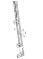
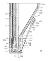
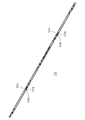
図20は表示モジュール50を示す一部縦断面図、図21は拡散板ホルダ54を示す斜視図、図22はソース基板32を取り付ける前のシャーシ28の一部を示す斜視図、図23はソース基板32を取り付けた後のシャーシ28の一部を示す斜視図である。
図中、図7と同一部分は同一符号を付して詳細な説明を省略する。
本発明の実施の形態4に係る表示モジュール50は、直下型の表示モジュールである。
図20は表示モジュール50を示す一部縦断面図、図21は拡散板ホルダ54を示す斜視図、図22はソース基板32を取り付ける前のシャーシ28の一部を示す斜視図、図23はソース基板32を取り付けた後のシャーシ28の一部を示す斜視図である。
図中、図7と同一部分は同一符号を付して詳細な説明を省略する。
表示モジュール50は、表示パネル21と、光学シート22と、拡散板51と、反射シート24と、LED基板(不図示)と、拡散板ホルダ54と、シャーシ28と、パネルシャーシ30とを備える。
表示動作の際には、拡散板51から面状の光が出射され、その光によって表示パネル21の背面が照明される。
表示動作の際には、拡散板51から面状の光が出射され、その光によって表示パネル21の背面が照明される。
シャーシ28は、例えば金属板を成形してなる箱状をなし、矩形状をなす平板部28aと、平板部28aの周縁から斜め外側に張り出すように設けられた側部28bと、側部28bの端縁部から平板部28aと略平行に外側に張り出すように設けられた縁部28cと、縁部28cに直角に連設され、拡散板51を覆う被覆部28dとを備える。そして、縁部28cの長手方向の両端部寄りには、矩形状の係止孔28e,28eが設けられている。
シャーシ28の内面には、反射シート24が当接されている。反射シート24は矩形状をなす平板部と、平板部の周縁から立ち上がる傾斜部と、傾斜部の端縁から張り出した縁部とを有する。
シャーシ28の平板部28aには、複数の前記LED基板がLEDのレンズ部が反射シート24から突出する状態で、平板部28aの短手方向に並設されている。
シャーシ28の平板部28aには、複数の前記LED基板がLEDのレンズ部が反射シート24から突出する状態で、平板部28aの短手方向に並設されている。
拡散板51は矩形板状をなし、表示パネル21側に対向する主面と、主面の反対面でシャーシ28に対向する裏面と、一対の長側面と、一対の短側面とを有する。裏面から入射した光は、散乱及び拡散されて、表示パネル21側に向かって出射する。
図21に示すように、拡散板ホルダ54は細長い板状をなし、両端部寄りに、2組の基板支持部54a及び係止部54cが設けられている。係止部54cは拡散板ホルダ54の上縁部に、拡散板ホルダ54の平面に直角に設けられ、基板支持部54aは、上縁部から斜め下方に延びるように設けられている。基板支持部54aの先端部には、側面視が三角形状をなす板係止部54bが設けられている。
光学シート22は、拡散シート、レンズシート及びDBEFシート(反射型偏光シート)等を含むシート群であり、拡散板51の主面側に配されている。そして、この光学シート22によって、拡散板51の主面から出射された光の拡散及び集光等が行われる。
パネルシャーシ30は、表示パネル支持部30b、側部支持部30f、及び拡散板挟持部30gを備える。パネルシャーシ30は略枠状をなし、すなわち表示パネル支持部30b及び拡散板挟持部30gと、側部30fとが、側面視で略L字状をなしている。
拡散板挟持部30gは表示パネル支持部30bの上部内側に連設されており、裏側に緩衝部材35を介在させた状態で拡散板51の表面の周縁部を支持するとともに、表側で光学シート22を保持している。側部30fは拡散板51の側部を支持している。
拡散板挟持部30gは表示パネル支持部30bの上部内側に連設されており、裏側に緩衝部材35を介在させた状態で拡散板51の表面の周縁部を支持するとともに、表側で光学シート22を保持している。側部30fは拡散板51の側部を支持している。
シャーシ28の係止孔28eの上縁部に、基板保持部54の係止部54cを係止させ、基板支持部54bを係止孔28eから突出させ、かつ表側に反射シート24の端部を載置した状態で、拡散板ホルダ54は拡散板51の端部を保持している。
表示パネル21の表面の周縁部とフロントキャビネット3との間に緩衝部材(不図示)が介在し、表示パネル21の裏面の周縁部と表示パネル支持部30bとの間に緩衝部材34が介在する状態で、表示パネル21はフロントキャビネット3及び表示パネル支持部30bに挟持されている。
以上の構成により、表示パネル21とバックライトとが一体化されている。
以上の構成により、表示パネル21とバックライトとが一体化されている。
本実施の形態においては、シャーシ28の側部28bの下寄りの部分に絶縁シート53が設けられている。絶縁シート53は細長い板状をなし、上縁部の長手方向の両端部寄りに切欠き53a,53aが設けられ、切欠き53a,53aより内側かつ下側に、矩形状の孔53b,53bが設けられている。すなわち、切欠き53aと係止孔28eとは絶縁シート53の長手方向にずれた状態で配置されている。
そして、本実施の形態においては、シャーシ28の側部28bに、絶縁シート53の切欠き53a,53aに嵌合する状態で、基板保持部52,52が設けられている。
基板保持部52は、ソース基板32の内面に当接する内面当接部52aと、内面当接部52aに直角に連設され、外側に延びてソース基板32の側面を覆う側面被覆部52bと、側面被覆部52bに直角に連設され、ソース基板32の外面に当接する外面当接部52cとを備える。
基板保持部52を側部28bに設けるときに、絶縁シート53の切り欠き53aに嵌合するので、精度良く基板保持部52の位置決めがなされる。
基板保持部52は、ソース基板32の内面に当接する内面当接部52aと、内面当接部52aに直角に連設され、外側に延びてソース基板32の側面を覆う側面被覆部52bと、側面被覆部52bに直角に連設され、ソース基板32の外面に当接する外面当接部52cとを備える。
基板保持部52を側部28bに設けるときに、絶縁シート53の切り欠き53aに嵌合するので、精度良く基板保持部52の位置決めがなされる。
表示パネル21のTFT基板の下側の長辺部分には、複数のソース側端子部(不図示)が設けられ、各ソース側端子部にはそれぞれ、フレキシブル基板からなるSOF基板31の一方の端部が接続されている。SOF基板31の、絶縁性及び可撓性を有する例えばポリイミド系樹脂等の合成樹脂材料からなるフィルム状の基材上には、液晶の駆動用のICチップ39が実装されている。SOF基板31の他方の端部はソース基板32の下側長辺部分に設けられた端子部(不図示)に接続されている。
SOF基板31は可撓性を有するので、撓みを利用して、ソース基板32の上側の長辺部分を容易に、基板保持部52の内面当接部52a及び外面当接部52c間に挿入して、ソース基板32を基板保持部52に係止することができる。すなわち、SOF基板31の反力により、ソース基板32は上側に押し上げられて、上側の長辺部分が基板保持部52に挟持される。
そして、本実施の形態においては、切欠き53aと千鳥配置された係止孔28eから突出された基板支持部54bにより、ソース基板32が下支えされており、外側へのずれは、板係止部54bにより抑止されているので、ソース基板32を良好に側部28bに固定することができる。
前記ICチップ39は、上述したように、放熱のため、近接する金属部分に当接させる必要がある。本実施の形態においては、アルミニウム製のフロントキャビネット3に当接させている。SOF基板31の撓みを利用して、SOF基板31がフロントキャビネット3に対して付勢されている。
本実施の形態に係る表示モジュール50は、以上のように構成されているので、シャーシ28の側部28bの形状(表示部保持体の側部の傾斜角度、及び側部の長さ等)に依らず、ソース基板31をシャーシ28に固定することができる。
実施の形態5.
本発明の実施の形態5に係る表示モジュール55は、直下型の表示モジュールである。
図24は表示モジュール55を示す一部縦断面図、図25は表示モジュール55を示す一部裏面図である。
図中、図20と同一部分は同一符号を付して詳細な説明を省略する。
本発明の実施の形態5に係る表示モジュール55は、直下型の表示モジュールである。
図24は表示モジュール55を示す一部縦断面図、図25は表示モジュール55を示す一部裏面図である。
図中、図20と同一部分は同一符号を付して詳細な説明を省略する。
本実施の形態に係るソース基板32は、実施の形態4に係るソース基板32より縦寸法が小さい。
上述したように、絶縁シート53は切欠き53aと、孔53bとを有しており、本実施の形態においては、孔53bにより位置決めをして基板保持部52がシャーシ28の側部28bに設けられている。
上述したように、絶縁シート53は切欠き53aと、孔53bとを有しており、本実施の形態においては、孔53bにより位置決めをして基板保持部52がシャーシ28の側部28bに設けられている。
本実施の形態に係るソース基板32も、実施の形態4に係るソース基板32と同様に、SOF基板31の撓みを利用して、ソース基板32の上側の長辺部分を容易に、基板保持部52の内面当接部52a及び外面当接部52c間に挿入して、ソース基板32を基板保持部52に係止することができる。すなわち、SOF基板31の反力により、ソース基板32は上側に押し上げられて、上側の長辺部分が基板保持部52に挟持される。
そして実施の形態4と同様に、切欠き53aと千鳥配置された係止孔28eから突出された基板支持部54bにより、ソース基板32が下支えされており、外側へのずれは、板係止部54bにより抑止されているので、ソース基板32を良好に側部28bに固定することができる。
以上のように構成されているので、本実施の形態においては、ソース基板31の縦寸法に依らず、絶縁シート53の切欠き53aと孔53bとのいずれかを選択して基板保持部52の位置を変えるのみで、ソース基板31をシャーシ28に固定することができる。
すなわち、ソース基板31の縦寸法の大小に合わせて、切欠き53a等の位置決め部を複数設けることで、シャーシ28及び絶縁シート53を共通化して、縦寸法が異なるソース基板31をシャーシ28に固定することができる。
従って、シャーシ28に複数のケガキ線を設ける必要がなく、貼り間違いが生じることがない。新しいケガキ線を設けるためにシャーシ28の金型を改造する必要もなく、絶縁シート53に新しく、位置決め部を設ければよい。
すなわち、ソース基板31の縦寸法の大小に合わせて、切欠き53a等の位置決め部を複数設けることで、シャーシ28及び絶縁シート53を共通化して、縦寸法が異なるソース基板31をシャーシ28に固定することができる。
従って、シャーシ28に複数のケガキ線を設ける必要がなく、貼り間違いが生じることがない。新しいケガキ線を設けるためにシャーシ28の金型を改造する必要もなく、絶縁シート53に新しく、位置決め部を設ければよい。
また、基板保持部52の位置を適切に決めることによって、実施の形態1と同様に、以下の効果も発生する。
SOF基板31に適度な弛みが発生し、その状態でソース基板32を基板保持部52に挿入することで、SOF基板31の弾力によって、SOF基板31の外面がフロントキャビネット3の内面に密着する。すると、SOF基板31の略中央部に配置されたICチップ39が、フロントキャビネット3に密着することになり、ICチップ39の熱が効率的にフロントキャビネット3に放出される。
SOF基板31が適度にフロントキャビネット3に付勢されていない場合、SOF基板31が揺れやすくなり、振動とそれによる擦れによって、SOF基板31が破損する可能性がある。また、SOF基板31が弛みのない状態である場合、振動及び落下、温度等でSOF基板31又は表示パネル21が動いた際にSOF基板31が引っ張られて切断されてしまう可能性もある。
SOF基板31に適度な弛みが発生し、その状態でソース基板32を基板保持部52に挿入することで、SOF基板31の弾力によって、SOF基板31の外面がフロントキャビネット3の内面に密着する。すると、SOF基板31の略中央部に配置されたICチップ39が、フロントキャビネット3に密着することになり、ICチップ39の熱が効率的にフロントキャビネット3に放出される。
SOF基板31が適度にフロントキャビネット3に付勢されていない場合、SOF基板31が揺れやすくなり、振動とそれによる擦れによって、SOF基板31が破損する可能性がある。また、SOF基板31が弛みのない状態である場合、振動及び落下、温度等でSOF基板31又は表示パネル21が動いた際にSOF基板31が引っ張られて切断されてしまう可能性もある。
以上のように、本発明に係る表示装置(1、50、55)は、映像を表示する表示パネル(21)を有する表示部(2)と、箱状をなし、該表示部の一部が開口から突出した状態で該表示部を収容して保持する表示部保持体(28)と、横長の矩形状をなし、一長辺部分を前記表示部保持体の開口に対向する底板の外面の一辺部分に沿うように配され、前記表示パネルを駆動する駆動基板(32)とを備える表示装置において、前記表示部保持体は、前記駆動基板の他長辺部分の一部を保持する基板保持部(29、52)を備えることを特徴とする。
本発明においては、基板保持部により駆動基板の上側の長辺部分を保持するように構成されているので、固定が柔軟性を有し、駆動基板と表示部とを接続するフレキシブル基板等の基板又は配線の長短が吸収され得、すなわち長い場合と短い場合とで撓みの度合が変わることで、該基板又は配線が断線するのが抑制されている。
駆動基板の基板保持部への固定は容易であり、作業工数を減じることができる。また、基板保持部の端部は保持体の側部の内側にあるので、従来の固定構造のように、製造時に基板保持部が破損する虞はない。従って、製造コストを減じることができる。
そして、表示部保持体の形状(表示部保持体の側部の傾斜角度、及び側部の長さ等)に依らず、駆動基板をシャーシに固定することができ、基板保持部を共通化させることができる。
駆動基板の基板保持部への固定は容易であり、作業工数を減じることができる。また、基板保持部の端部は保持体の側部の内側にあるので、従来の固定構造のように、製造時に基板保持部が破損する虞はない。従って、製造コストを減じることができる。
そして、表示部保持体の形状(表示部保持体の側部の傾斜角度、及び側部の長さ等)に依らず、駆動基板をシャーシに固定することができ、基板保持部を共通化させることができる。
本発明に係る表示装置(1)は、前記表示パネルを保持するパネル保持体(30)を備えており、前記パネル保持体は、前記表示部保持体の側面を支持し、かつ前記駆動基板側へ突出した突起部(30a)を備えることを特徴とする。
本発明においては、万一、振動等により駆動基板が下側に動いた場合でも、落下するのが抑止される。
本発明に係る表示装置(50、55)は、前記駆動基板の前記一長辺部分の一部を支持する基板支持部(54a)を備えることを特徴とする。
本発明においては、駆動基板を下支えすることができ、駆動基板の表示部保持体への固定が良好になる。
本発明に係る表示装置(50、55)は、光源と、該光源から照射された光を拡散する拡散板(51)と、該拡散板を前記表示部保持体内で支持する拡散板支持体(54)とを備え、前記拡散板支持体は、前記基板支持部を備えることを特徴とする。
本発明においては、拡散板の端縁部を支持する拡散板支持体に基板支持部を設けてあり、該基板支持部を拡散板支持体から少し突出させるように設けることで、簡単な構成で、容易に駆動基板を下支えすることができる。
本発明に係る表示装置(1、50、55)は、前記表示部保持体と前記駆動基板との間に介在される絶縁シート(53)を備え、該絶縁シートは、前記基板保持部を位置決めするための位置決め部(53a、53b)を備えることを特徴とする。
本発明においては、表示部保持体にケガキ線を設けることなく、表示部保持体に絶縁シートを配した後、位置決め部により基板保持部を設けることができる。
本発明に係る表示装置(1、50、55)は、前記絶縁シートは、縦方向の位置が異なる複数の位置決め部を備えることを特徴とする。
表示部保持体に基板保持部を設ける場合に、ケガキ線に合わせて設けることにした場合、共通の表示部保持体に複数のケガキ線を設けることになり、貼り間違いが生じる虞がある。また、新しいケガキ線を設ける場合、金型を改造する必要がある。
本発明においては、駆動基板の縦寸法の大小に合わせて、位置決め部を複数設けることで、表示部保持体及び絶縁シートを共通化して、縦寸法が異なる駆動基板を表示部保持体に固定することができる。
従って、表示部保持体に複数のケガキ線を設ける必要がなく、貼り間違いが生じることがない。新しいケガキ線を設けるために金型を改造する必要もなく、絶縁シートに新しく、位置決め部を設ければよい。
本発明においては、駆動基板の縦寸法の大小に合わせて、位置決め部を複数設けることで、表示部保持体及び絶縁シートを共通化して、縦寸法が異なる駆動基板を表示部保持体に固定することができる。
従って、表示部保持体に複数のケガキ線を設ける必要がなく、貼り間違いが生じることがない。新しいケガキ線を設けるために金型を改造する必要もなく、絶縁シートに新しく、位置決め部を設ければよい。
本発明に係る表示装置(1、50、55)は、前記表示部の周縁部を覆う前キャビネット(3)と、前記表示部及び前記駆動基板を接続するフレキシブル基板(31)とをさらに備え、前記フレキシブル基板は、前記前キャビネットの内面に当接可能に構成されていることを特徴とする。
本発明においては、基板保持部の位置を適切に決めることにより、以下の効果が生じる。
フレキシブル基板に適度な弛みが発生し、その状態で、駆動基板を基板保持部(29、52)に挿入することで、フレキシブル基板の弾力によって、フレキシブル基板の外面が、表示部の周縁部を覆う前キャビネットの内面に密着する。すると、フレキシブル基板に配置されたICチップが、前キャビネットに密着することになり、ICチップの熱を効率的に前キャビネットに放熱することができる。
フレキシブル基板が適度に前キャビネットに付勢されていない場合、フレキシブル基板が揺れやすくなり、振動とそれによる擦れによって、フレキシブル基板が破損する可能性がある。また、フレキシブル基板が、弛みがない状態である場合、振動及び落下、温度等でフレキシブル基板及び表示パネルが動いた際にフレキシブル基板が引っ張られて切断されてしまう可能性もある。
フレキシブル基板に適度な弛みが発生し、その状態で、駆動基板を基板保持部(29、52)に挿入することで、フレキシブル基板の弾力によって、フレキシブル基板の外面が、表示部の周縁部を覆う前キャビネットの内面に密着する。すると、フレキシブル基板に配置されたICチップが、前キャビネットに密着することになり、ICチップの熱を効率的に前キャビネットに放熱することができる。
フレキシブル基板が適度に前キャビネットに付勢されていない場合、フレキシブル基板が揺れやすくなり、振動とそれによる擦れによって、フレキシブル基板が破損する可能性がある。また、フレキシブル基板が、弛みがない状態である場合、振動及び落下、温度等でフレキシブル基板及び表示パネルが動いた際にフレキシブル基板が引っ張られて切断されてしまう可能性もある。
本発明に係る表示装置(1)は、映像を表示する表示部(2)と、箱状をなし、該表示部の一部が開口から突出した状態で該表示部を収容して保持する保持体(28)と、横長の矩形状をなし、一長辺部分が前記保持体の開口に対向する底面の外面の一辺部分に沿うように設けられた絶縁シート(36)と、該絶縁シート上に設けられ、前記表示部を駆動する駆動基板(32)とを備える表示装置において、前記絶縁シートは、前記駆動基板の他長辺部分の一部を保持する基板保持部(37)を備えることを特徴とする。
本発明においては、基板保持部により駆動基板の上側の長辺部分が保持され、駆動基板の下側の長辺部分は係止しないので、固定が柔軟性を有し、駆動基板と表示部とを接続する基板又は配線の長短が吸収され得、該基板又は配線が断線するのが抑制されている。
駆動基板の基板保持部への固定は容易であり、作業工数を減じることができる。
また、基板保持部の端部は保持体の側部の内側にあるので、製造時に基板保持部が破損する虞はない。
駆動基板の基板保持部への固定は容易であり、作業工数を減じることができる。
また、基板保持部の端部は保持体の側部の内側にあるので、製造時に基板保持部が破損する虞はない。
本発明に係る表示装置は、前記絶縁シートは、前記一長辺部分に設けられ、前記駆動基板側へ突出した突起部(38)を有することを特徴とする。
本発明においては、万一、振動等により駆動基板が下側に動いた場合でも、落下するのが抑止される。
本発明に係る表示装置(1)は、映像を表示する表示パネル(21)と、矩形平板状をなし、光を前記表示パネルへ出射して該表示パネルを照射する導光板(23)と、前記導光板の側面又は平面へ光を入射させる光源(25)と、箱状をなし、前記導光板、及び前記光源を収容して保持する光源保持体(28)と、前記導光板を前記光源保持体内で支持する導光板支持体(26)と、横長の矩形状をなし、一長辺部分が前記光源保持体の開口に対向する底板の外面の一辺部分に沿うように配され、前記表示パネルを駆動する駆動基板(32)とを備える表示装置において、前記導光板支持体は、前記駆動基板の他長辺部分の一部を保持する基板保持部(40)を備えることを特徴とする。
本発明においては、基板保持部により駆動基板の上側の長辺部分が保持され、駆動基板の下側の長辺部分は係止しないので、固定が柔軟性を有し、駆動基板と表示部とを接続する基板又は配線の長短が吸収され得、該基板又は配線が断線するのが抑制されている。
駆動基板の基板保持部への固定は容易であり、作業工数を減じることができる。
また、基板保持部の端部は保持体の側部の内側にあるので、製造時に基板保持部が破損する虞はない。
駆動基板の基板保持部への固定は容易であり、作業工数を減じることができる。
また、基板保持部の端部は保持体の側部の内側にあるので、製造時に基板保持部が破損する虞はない。
本発明に係るTV受信機(1)は、上述のいずれかの表示装置と、テレビジョン放送を受信する受信部とを備え、前記受信部にて受信したテレビジョン放送に基づいて、前記表示装置に映像を表示するようにしてあることを特徴とする。
本発明においては、駆動基板の固定が容易であり、製造時に基板保持部が破損する虞がなく、作業性工数を減じ、容易に不良品が生じることなく、製造され得る。
本発明は上述した実施の形態の内容に限定されるものではなく、請求項に示した範囲で種々の変更が可能である。すなわち、請求項に示した範囲で適宜変更した技術的手段を組み合わせて得られる実施形態も本発明の技術的範囲に含まれる。
例えば前記実施の形態においては、駆動基板としてソース基板32を適用した場合につき説明しているが、これに限定されるものではない。駆動基板としてゲート基板を適用することも可能である。
例えば前記実施の形態においては、駆動基板としてソース基板32を適用した場合につき説明しているが、これに限定されるものではない。駆動基板としてゲート基板を適用することも可能である。
1、50、55 TV受信機
2 表示モジュール
21 表示パネル
22 光学シート
23 導光板
24 反射シート
25 LED基板
26 導光板ホルダ
27 ヒートスプレッダ
28 シャーシ
28a 平板部
28b 側部
28c 縁部
28d 被覆部
28e 係止孔
29、37、40、52 基板保持部
29a、52a 内面当接部
29b、37b、40a、52b 側面被覆部
29c、37c 外面被覆部
52c 外面当接部
37a 基部
40b 外面当接部
30 パネルシャーシ
30a 突起部
30e シャーシ支持部
30g 拡散板挟持部
31 SOF基板
32 ソース基板
38 突起部
38a 基部
38b 側面被覆部
3 フロントキャビネット
4 リアキャビネット
6 スタンド
11 チューナ
51 拡散板
53 絶縁シート
53a 切欠き
53b 孔
54 拡散板ホルダ
54a 基板支持部
54b 板係止部
54c 係止部
2 表示モジュール
21 表示パネル
22 光学シート
23 導光板
24 反射シート
25 LED基板
26 導光板ホルダ
27 ヒートスプレッダ
28 シャーシ
28a 平板部
28b 側部
28c 縁部
28d 被覆部
28e 係止孔
29、37、40、52 基板保持部
29a、52a 内面当接部
29b、37b、40a、52b 側面被覆部
29c、37c 外面被覆部
52c 外面当接部
37a 基部
40b 外面当接部
30 パネルシャーシ
30a 突起部
30e シャーシ支持部
30g 拡散板挟持部
31 SOF基板
32 ソース基板
38 突起部
38a 基部
38b 側面被覆部
3 フロントキャビネット
4 リアキャビネット
6 スタンド
11 チューナ
51 拡散板
53 絶縁シート
53a 切欠き
53b 孔
54 拡散板ホルダ
54a 基板支持部
54b 板係止部
54c 係止部
Claims (10)
- 映像を表示する表示パネルを有する表示部と、箱状をなし、該表示部の一部が開口から突出した状態で該表示部を収容して保持する表示部保持体と、横長の矩形状をなし、一長辺部分を前記表示部保持体の開口に対向する底板の外面の一辺部分に沿うように配され、前記表示パネルを駆動する駆動基板とを備える表示装置において、
前記表示部保持体は、前記駆動基板の他長辺部分の一部を保持する基板保持部を備えることを特徴とする表示装置。 - 前記表示パネルを保持するパネル保持体を備えており、
前記パネル保持体は、前記表示部保持体の側面を支持し、かつ前記駆動基板側へ突出した突起部を備えることを特徴とする請求項1に記載の表示装置。 - 前記駆動基板の前記一長辺部分の一部を支持する基板支持部を備えることを特徴とする請求項1に記載の表示装置。
- 光源と、該光源から照射された光を拡散する拡散板と、該拡散板を前記表示部保持体内で支持する拡散板支持体とを備え、
前記拡散板支持体は、前記基板支持部を備えることを特徴とする請求項3に記載の表示装置。 - 前記表示部保持体と前記駆動基板との間に介在される絶縁シートを備え、
該絶縁シートは、前記基板保持部を位置決めするための位置決め部を備えることを特徴とする請求項1から4までのいずれか1項に記載の表示装置。 - 前記絶縁シートは、縦方向の位置が異なる複数の位置決め部を備えることを特徴とする請求項5に記載の表示装置。
- 前記表示部の周縁部を覆う前キャビネットと、前記表示部及び前記駆動基板を接続するフレキシブル基板とをさらに備え、
前記フレキシブル基板は、前記前キャビネットの内面に当接可能に構成されていることを特徴とする請求項5又は6に記載の表示装置。 - 映像を表示する表示部と、箱状をなし、該表示部の一部が開口から突出した状態で該表示部を収容して保持する保持体と、横長の矩形状をなし、一長辺部分が前記保持体の開口に対向する底面の外面の一辺部分に沿うように設けられた絶縁シートと、該絶縁シート上に設けられ、前記表示部を駆動する駆動基板とを備える表示装置において、
前記絶縁シートは、前記駆動基板の他長辺部分の一部を保持する基板保持部を備えることを特徴とする表示装置。 - 映像を表示する表示パネルと、矩形平板状をなし、光を前記表示パネルへ出射して該表示パネルを照射する導光板と、前記導光板の側面又は平面へ光を入射させる光源と、箱状をなし、前記導光板、及び前記光源を収容して保持する光源保持体と、前記導光板を前記光源保持体内で支持する導光板支持体と、横長の矩形状をなし、一長辺部分が前記光源保持体の開口に対向する底板の外面の一辺部分に沿うように配され、前記表示パネルを駆動する駆動基板とを備える表示装置において、
前記導光板支持体は、前記駆動基板の他長辺部分の一部を保持する基板保持部を備えることを特徴とする表示装置。 - 請求項1から9までのいずれか1項に記載の表示装置と、
テレビジョン放送を受信する受信部と
を備え、
前記受信部にて受信したテレビジョン放送に基づいて、前記表示装置に映像を表示するようにしてあることを特徴とするテレビジョン受信機。
Applications Claiming Priority (4)
| Application Number | Priority Date | Filing Date | Title |
|---|---|---|---|
| JP2014-117932 | 2014-06-06 | ||
| JP2014117932 | 2014-06-06 | ||
| JP2015-047576 | 2015-03-10 | ||
| JP2015047576 | 2015-03-10 |
Publications (1)
| Publication Number | Publication Date |
|---|---|
| WO2015186758A1 true WO2015186758A1 (ja) | 2015-12-10 |
Family
ID=54766826
Family Applications (1)
| Application Number | Title | Priority Date | Filing Date |
|---|---|---|---|
| PCT/JP2015/066099 Ceased WO2015186758A1 (ja) | 2014-06-06 | 2015-06-03 | 表示装置、及びテレビジョン受信機 |
Country Status (1)
| Country | Link |
|---|---|
| WO (1) | WO2015186758A1 (ja) |
Cited By (3)
| Publication number | Priority date | Publication date | Assignee | Title |
|---|---|---|---|---|
| CN110007495A (zh) * | 2019-04-10 | 2019-07-12 | 深圳市华星光电技术有限公司 | 显示装置 |
| US11442307B2 (en) * | 2019-10-31 | 2022-09-13 | K-Tronics (Suzhou) Technology Co., Ltd. | Backlight module, display module and assembling method thereof |
| US11829032B2 (en) | 2019-10-31 | 2023-11-28 | K-Tronics (Suzhou) Technology Co., Ltd. | Backlight module including fixing member, display module and assembling method thereof |
Citations (6)
| Publication number | Priority date | Publication date | Assignee | Title |
|---|---|---|---|---|
| JPS6230239U (ja) * | 1985-08-08 | 1987-02-23 | ||
| JP2008003242A (ja) * | 2006-06-21 | 2008-01-10 | Sharp Corp | 表示パネル保持部材および表示装置 |
| JP2009294377A (ja) * | 2008-06-04 | 2009-12-17 | Sharp Corp | 表示装置、及びテレビ受信装置 |
| JP2013164575A (ja) * | 2012-01-13 | 2013-08-22 | Sharp Corp | 表示装置およびテレビジョン受像機 |
| WO2014002779A1 (ja) * | 2012-06-29 | 2014-01-03 | ソニー株式会社 | 表示装置 |
| JP2014032305A (ja) * | 2012-08-03 | 2014-02-20 | Sony Corp | 表示装置およびその製造方法、並びにソース基板保持部材 |
-
2015
- 2015-06-03 WO PCT/JP2015/066099 patent/WO2015186758A1/ja not_active Ceased
Patent Citations (6)
| Publication number | Priority date | Publication date | Assignee | Title |
|---|---|---|---|---|
| JPS6230239U (ja) * | 1985-08-08 | 1987-02-23 | ||
| JP2008003242A (ja) * | 2006-06-21 | 2008-01-10 | Sharp Corp | 表示パネル保持部材および表示装置 |
| JP2009294377A (ja) * | 2008-06-04 | 2009-12-17 | Sharp Corp | 表示装置、及びテレビ受信装置 |
| JP2013164575A (ja) * | 2012-01-13 | 2013-08-22 | Sharp Corp | 表示装置およびテレビジョン受像機 |
| WO2014002779A1 (ja) * | 2012-06-29 | 2014-01-03 | ソニー株式会社 | 表示装置 |
| JP2014032305A (ja) * | 2012-08-03 | 2014-02-20 | Sony Corp | 表示装置およびその製造方法、並びにソース基板保持部材 |
Cited By (3)
| Publication number | Priority date | Publication date | Assignee | Title |
|---|---|---|---|---|
| CN110007495A (zh) * | 2019-04-10 | 2019-07-12 | 深圳市华星光电技术有限公司 | 显示装置 |
| US11442307B2 (en) * | 2019-10-31 | 2022-09-13 | K-Tronics (Suzhou) Technology Co., Ltd. | Backlight module, display module and assembling method thereof |
| US11829032B2 (en) | 2019-10-31 | 2023-11-28 | K-Tronics (Suzhou) Technology Co., Ltd. | Backlight module including fixing member, display module and assembling method thereof |
Similar Documents
| Publication | Publication Date | Title |
|---|---|---|
| JP5032650B2 (ja) | テレビおよび電子機器 | |
| US10036848B2 (en) | Lighting device, display device, and television device | |
| US9507080B2 (en) | Lighting device, display device and television device | |
| CN104094336B (zh) | 显示装置和电视接收装置 | |
| CN104185811A (zh) | 显示装置和电视接收装置 | |
| KR20100035624A (ko) | 액정표시장치 및 이를 구비하는 텔레비전 장치 | |
| CN104508355A (zh) | 照明装置、显示装置以及电视接收装置 | |
| WO2012169441A1 (ja) | 照明装置、表示装置及びテレビ受信装置 | |
| US9904084B2 (en) | Display apparatus | |
| WO2015186758A1 (ja) | 表示装置、及びテレビジョン受信機 | |
| CN104040413B (zh) | 显示装置和电视接收装置 | |
| WO2013191051A1 (ja) | 表示装置、及びテレビ受信装置 | |
| WO2012053442A1 (ja) | 照明装置および表示装置 | |
| US20160102847A1 (en) | Lighting device, display device, and television receiving device | |
| US10345513B2 (en) | Display device | |
| US10613361B2 (en) | Display device | |
| US10302982B2 (en) | Display apparatus | |
| KR101227597B1 (ko) | 백라이트 유닛 및 이를 구비하는 액정표시장치와 텔레비전 장치 | |
| US10514493B2 (en) | Display device | |
| JP2008251220A (ja) | バックライトユニットおよび表示装置 | |
| CN104272177A (zh) | 显示装置和电视接收装置 | |
| JP2014077927A (ja) | テレビおよび電子機器 | |
| US20150103259A1 (en) | Lighting device, display device and television device | |
| CN105264412A (zh) | 照明装置、显示装置以及电视接收装置 | |
| JP5865065B2 (ja) | 面発光装置、画像表示装置、及びテレビジョン受像装置 |
Legal Events
| Date | Code | Title | Description |
|---|---|---|---|
| 121 | Ep: the epo has been informed by wipo that ep was designated in this application |
Ref document number: 15802510 Country of ref document: EP Kind code of ref document: A1 |
|
| NENP | Non-entry into the national phase |
Ref country code: DE |
|
| 122 | Ep: pct application non-entry in european phase |
Ref document number: 15802510 Country of ref document: EP Kind code of ref document: A1 |
|
| NENP | Non-entry into the national phase |
Ref country code: JP |