WO2015182741A1 - 校正システム、太陽光発電用監視システム、及び校正方法 - Google Patents
校正システム、太陽光発電用監視システム、及び校正方法 Download PDFInfo
- Publication number
- WO2015182741A1 WO2015182741A1 PCT/JP2015/065540 JP2015065540W WO2015182741A1 WO 2015182741 A1 WO2015182741 A1 WO 2015182741A1 JP 2015065540 W JP2015065540 W JP 2015065540W WO 2015182741 A1 WO2015182741 A1 WO 2015182741A1
- Authority
- WO
- WIPO (PCT)
- Prior art keywords
- current
- calibration
- current sensor
- current value
- sensor
- Prior art date
- Legal status (The legal status is an assumption and is not a legal conclusion. Google has not performed a legal analysis and makes no representation as to the accuracy of the status listed.)
- Ceased
Links
Images
Classifications
-
- G—PHYSICS
- G01—MEASURING; TESTING
- G01R—MEASURING ELECTRIC VARIABLES; MEASURING MAGNETIC VARIABLES
- G01R19/00—Arrangements for measuring currents or voltages or for indicating presence or sign thereof
-
- G—PHYSICS
- G01—MEASURING; TESTING
- G01R—MEASURING ELECTRIC VARIABLES; MEASURING MAGNETIC VARIABLES
- G01R35/00—Testing or calibrating of apparatus covered by the other groups of this subclass
-
- Y—GENERAL TAGGING OF NEW TECHNOLOGICAL DEVELOPMENTS; GENERAL TAGGING OF CROSS-SECTIONAL TECHNOLOGIES SPANNING OVER SEVERAL SECTIONS OF THE IPC; TECHNICAL SUBJECTS COVERED BY FORMER USPC CROSS-REFERENCE ART COLLECTIONS [XRACs] AND DIGESTS
- Y02—TECHNOLOGIES OR APPLICATIONS FOR MITIGATION OR ADAPTATION AGAINST CLIMATE CHANGE
- Y02E—REDUCTION OF GREENHOUSE GAS [GHG] EMISSIONS, RELATED TO ENERGY GENERATION, TRANSMISSION OR DISTRIBUTION
- Y02E10/00—Energy generation through renewable energy sources
- Y02E10/50—Photovoltaic [PV] energy
Definitions
- the present invention relates to a calibration system for calibrating a current sensor used in a photovoltaic power generation system, a monitoring system for photovoltaic power generation, and a calibration method.
- a configuration is adopted in which a large number of solar power generation panels of a predetermined size are arranged and these outputs are aggregated in a junction box.
- a so-called mega solar (large-scale solar power plant) a large number of strings are formed by connecting a plurality of photovoltaic panels, and the output of each string is aggregated by connecting these strings to a connection box. May be configured to feed into a power converter.
- the power generation amount output by the string is monitored based on the output of the sensor for measuring the power generation amount. Therefore, if the accuracy of this sensor decreases, the power generation amount of the string cannot be accurately grasped. There is a risk that proper monitoring will not be possible.
- This invention is made
- a calibration system is a calibration system that calibrates a current sensor that measures a generated current of a photovoltaic power generation panel, and the current sensor outputs an output circuit for outputting the generated power of the photovoltaic power generation panel.
- a calibration circuit that is arranged so that the current value is measured by the current sensor together with the output circuit, and a calibration current having a predetermined current value is supplied to the calibration circuit.
- a calibration processing unit that calibrates the current sensor based on a difference from the second current value measured by the sensor.
- the monitoring system for photovoltaic power generation is a monitoring system for photovoltaic power generation that monitors the state of the photovoltaic power generation panel, the current sensor that measures the generated current of the photovoltaic power generation panel, and the above-described And a calibration system.
- the calibration method is a current sensor that measures a power generation current of a photovoltaic power generation panel, and is configured to measure a current value of an output circuit for outputting the photovoltaic power generation panel.
- a calibration method for calibrating a current sensor comprising: supplying a calibration current having a predetermined current value to a calibration circuit arranged so that a current value is measured by the current sensor together with the output circuit; and the calibration A first current value measured by the current sensor when the calibration current is not supplied to the calibration circuit, and a first current value measured by the current sensor when the calibration current is supplied to the calibration circuit.
- a calibration processing step of calibrating the current sensor based on a difference from two current values.
- each said embodiment can be implement
- the current sensor used in the photovoltaic power generation system can be easily calibrated.
- a calibration system is a calibration system that calibrates a current sensor that measures a power generation current of a solar power generation panel, and the current sensor outputs power generated by the solar power generation panel.
- the calibration circuit is configured to measure the current value of the output circuit, and is arranged so that the current value is measured by the current sensor together with the output circuit, and the calibration current having a predetermined current value in the calibration circuit
- a calibration processing unit that calibrates the current sensor based on a difference from the second current value measured by the current sensor.
- the calibration system configured as described above, if a calibration circuit is provided and a calibration current having a predetermined current value is supplied to the calibration circuit, the difference between the first current value and the second current value is obtained.
- the current sensor can be easily calibrated by comparing the difference with the current value of the calibration current.
- the calibration circuit is arranged so that a current value is measured by the plurality of current sensors by one circuit. It is preferable. In this case, even if there are a plurality of solar panels and current sensors, if a calibration current having a predetermined current value is supplied to the calibration circuit, the calibration current can be supplied to each of the plurality of current sensors, and calibration is performed. Can do. Therefore, it is not necessary to calibrate each current sensor individually, and it is possible to easily calibrate a plurality of current sensors.
- the calibration processing unit is configured to measure the first current value measured when the solar power generation panel is not generating power and when the solar power generation panel is not generating power.
- the current sensor may be calibrated based on the difference from the measured second current value.
- the calibration processing unit can calibrate using the difference obtained based on the calibration current supplied to the calibration circuit. For this reason, it is possible to perform calibration more accurately without being affected by fluctuations in current other than the calibration current.
- the calibration system may further include an abnormality detection unit that detects an abnormality of the current sensor based on a calibration result by the calibration processing unit.
- an abnormality detection unit that detects an abnormality of the current sensor based on a calibration result by the calibration processing unit.
- a current value output by the current sensor Can be determined whether an abnormality has occurred in the current sensor or an abnormality in the photovoltaic power generation panel.
- the current sensor includes an annular member that generates a magnetic flux when the output electric circuit is disposed inside and an electric current flows through the output electric circuit, and a signal that indicates a current value of a current that flows by detecting the generated magnetic flux.
- the calibration electric circuit is preferably arranged inside the annular member together with the output electric circuit. In this case, the calibration circuit can be arranged with a simple configuration so that the current value is measured by the current sensor together with the output circuit.
- the monitoring system for photovoltaic power generation which is one Embodiment is a monitoring system for photovoltaic power generation which monitors the state of a photovoltaic power generation panel, Comprising: The current sensor which measures the electric power generation current of the said photovoltaic power generation panel And the calibration system according to (1) above, It has.
- the calibration method which is one Embodiment is a current sensor which measures the electric power generation current of a photovoltaic power generation panel, and is comprised so that the electric current value of the output circuit for outputting the said photovoltaic power generation panel may be measured.
- a calibration method for calibrating a current sensor wherein a supply step supplies a calibration current having a predetermined current value to a calibration circuit arranged so that a current value is measured by the current sensor together with the output circuit. First current value measured by the current sensor when the calibration current is not supplied to the calibration circuit, and measured by the current sensor when the calibration current is supplied to the calibration circuit
- the current sensor used in the photovoltaic power generation system can be easily calibrated.
- each said embodiment is implement
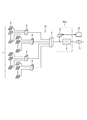
- FIG. 1 is a single-line system diagram showing an example of the overall configuration of a photovoltaic power generation monitoring system.
- the system includes one current collection system P1.
- the direct current outputs of a large number of photovoltaic power generation panels 1 are collected into a plurality of connection boxes 4 (four in the example) for each predetermined number. Further, the outputs are collected from the four connection boxes 4 to a higher current collection box 5.
- the output from the current collection box 5 is converted into alternating current by the power converter 7 and can provide alternating current power to the commercial power system via the transformer 11.
- connection boxes 4 includes a sensor for measuring the generated power (current / voltage) of the photovoltaic power generation panel 1 connected to each connection box 4 and a slave unit for power line communication that transmits information indicating the measurement result (
- a PLC also referred to as a power line communication unit
- a power line communication parent device (hereinafter also referred to as “PLC parent device”) 9 is connected to a DC electric circuit from the current collection box 5 to the power converter 7.
- the PLC master unit 9 receives and acquires information transmitted from the PLC slave unit through power line communication.
- the PLC master device 9 is connected to the monitoring device 10 via, for example, a LAN (Local Area Network) wiring.
- the PLC master device 9 is mounted on the power conditioner PC1 together with the power converter 7.
- the PLC master device 9 does not necessarily have to be mounted inside the power conditioner PC1, and may be in the vicinity of the power conditioner PC1. In short, it is sufficient that the PLC master unit 9 is provided along with the current collecting terminal (the input side of the power converter 7) of the current collecting system P1. However, here, the description will be made assuming that the PLC master unit 9 is provided in the power conditioner PC1.
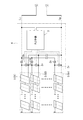
- FIG. 2 is a circuit diagram illustrating an example of the configuration of the plurality of photovoltaic power generation panels 1 and the connection box 4 to which the photovoltaic power generation panels 1 are connected.
- the plurality of photovoltaic power generation panels 1 connected to the connection box 4 constitute a plurality of strings S.
- the string S is configured by connecting a predetermined number of photovoltaic power generation panels 1 in series-parallel, for example, and constitutes a unit for connecting a plurality of photovoltaic power generation panels 1 to the connection box 4.
- a plurality of strings S are connected to the connection box 4 in parallel, and the generated power of each string S is collected.
- connection box 4 there are provided a current sensor 2a and a voltage sensor 2v for measuring the current and voltage output corresponding to each string S, respectively.
- the current sensor 2a measures the current flowing through the electric circuit connecting the junction box 4 and the string S.
- the voltage sensor 2v measures the voltage of the electric circuit connecting the junction box 4 and the string S.
- the current sensor 2a and the voltage sensor 2v output information indicating the measured current value and voltage value as sensor outputs. Based on the current value and the voltage value indicated by the sensor outputs of the current sensor 2a and the voltage sensor 2v, the generated power value as the power generation amount of the corresponding string S is obtained. Since the voltage change is small, the current value measured by the current sensor 2a can be considered as the power generation amount of the corresponding string S.
- the aforementioned PLC slave unit 3 is provided inside the junction box 4.
- the PLC slave unit 3 is provided with sensor outputs of the current sensor 2a and the voltage sensor 2v.
- the PLC slave unit 3 collects the sensor output indicating the measurement result by the current sensor 2a and the sensor output indicating the measurement result by the voltage sensor 2v, and the string corresponding to the sensor 2a, 2v based on the sensor output by the sensor 2a, 2v. S current value information and voltage value information are generated.
- the PLC slave unit 3 transmits the current value information and voltage value information of the generated string S to the PLC master unit 9 by power line communication. Further, the PLC slave unit 3 has a function of executing calibration of the current sensor 2a and also has a function of detecting whether or not the current sensor 2a is abnormal. This will be described in detail later.
- the PLC slave unit 3 does not necessarily have to be provided inside the connection box 4 and may be in the vicinity of the connection box 4. In short, it is sufficient that the PLC slave unit 3 is provided along with the connection box 4. However, it demonstrates here that the PLC subunit
- the DC path L P is connected to L N, the current information and the voltage value information of the string S, the DC path L P, is transmitted by the power line communication put to L N.
- the transmission signal by this power line communication reaches the input side of the power conversion device 7 which is the current collecting terminal via the upper current collecting box 5 (FIG. 1).
- the voltage value information and the voltage value information transmitted by the PLC slave unit 3 are output from the connection box 4, pass through the current collection box 5, reach the input side of the power converter 7, and are connected to the PLC parent. Is given to machine 9 (FIG. 1). Further, the voltage value information and the voltage value information are given from the PLC master unit 9 to the monitoring device 10. The monitoring device 10 recognizes the current value and voltage value of each string S (solar power generation panel 1) based on the voltage value information and voltage value information given from the PLC slave unit 3, and monitors each string S.
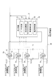
- FIG. 3 is a diagram showing details of the current sensor 2a and the PLC slave unit in the connection box 4, and shows a configuration of a calibration system that performs calibration of the current sensor 2a.
- the plurality of strings S are connected to the connection box 4, and in FIG. 3, the illustration of the plurality of strings S is omitted, and the output for outputting the generated power extending from the plurality of strings S is output.
- the electric circuit L is shown.
- a plurality of strings S are shown as strings S1, S2, S3... Sn in order from the top of the page, and corresponding output circuits L are shown as output circuits L1, L2, L3,. Yes.
- the description will be given focusing on the current sensor 2a provided in the output electric circuit L1 through which the generated current of the string S1 flows.
- the other current sensors 2a have the same configuration.
- the current sensor 2 a is configured to include a ferrite core 15 that is an annular member and a Hall element 16.
- the ferrite core 15 is disposed on the outer peripheral side of the output electric circuit L1 for outputting the generated electric power generated by the string S1.
- the ferrite core 15 is formed in a C shape, and an air gap is provided in a part in the circumferential direction.
- the hall element 16 is disposed in the air gap of the ferrite core 15 and outputs a voltage signal corresponding to the magnetic flux density in the air gap as a sensor output.
- the current sensor 2a detects the magnetic flux generated in the ferrite core 15 when a current flows through the output electric circuit L1 disposed inside the ferrite core 15 by the Hall element 16, converts the detected magnetic flux into a voltage, and outputs the sensor. Is output to the PLC slave unit 3.
- the magnetic flux density generated in the ferrite core 15 changes according to the current value of the current flowing through the output electric circuit L1.
- the Hall element 16 outputs a voltage signal corresponding to the magnetic flux density in the air gap as a sensor output. Therefore, the sensor output that the current sensor 2a detects and outputs the magnetic flux generated by the current in the output electric circuit L1 indicates the value of the current flowing through the output electric circuit L1.
- a calibration circuit 20 used for calibrating the current sensor 2a is inserted inside the ferrite core 15 of the current sensor 2a of the present embodiment.
- the calibration circuit 20 is inserted inside the ferrite core 15 together with the output circuit L1, and is arranged such that the current value of the current flowing through the calibration circuit 20 is measured by the current sensor 2a together with the output circuit L1. .
- the calibration electric circuit 20 is constituted by one electric circuit, and is disposed through the inside of the ferrite core 15 of each current sensor 2a provided corresponding to each string S. That is, the calibration circuit 20 is arranged so that the current is measured by each current sensor 2a by one circuit.
- the calibration electric circuit 20 is connected to the PLC slave unit 3, and a calibration current that is a direct current is supplied from the PLC slave unit 3 as described later.
- the calibration circuit 20 is arranged so that the calibration current supplied from the PLC slave unit 3 flows in a direction coinciding with the current flow direction in the output circuits L1, L2,. Yes.
- the current sensor 2a since the calibration electric circuit 20 is arranged together with the output electric circuit L1 inside the ferrite core 15, when the electric current is supplied to the calibration electric circuit 20 together with the magnetic flux when the electric current is supplied to the output electric circuit L1. The magnetic flux is also detected. Therefore, the current sensor 2a can measure a current value obtained by combining the current flowing through the output circuit L1 and the current flowing through the calibration circuit 20.
- the current sensor 2a measures the current value of the current flowing through the output electric circuit L1 if the current flows only through the output electric circuit L1.
- the current sensor 2 a measures the current value of the current flowing through the calibration circuit 20 if the current flows only through the calibration circuit 20.
- the current sensor 2a measures the total current value of the currents flowing through both the electric circuits L1 and 20 if the current flows through both the output electric circuit L1 and the calibration electric circuit 20.
- the PLC slave unit 3 includes a microcomputer including a processor, a ROM, a RAM, and a storage unit in addition to a functional unit that executes power line communication.
- a microcomputer including a processor, a ROM, a RAM, and a storage unit in addition to a functional unit that executes power line communication.
- various computer programs for realizing the functions of the PLC slave unit 3 are stored.
- the PLC slave unit 3 implements each necessary function and a function unit described later by executing these computer programs.
- the PLC slave unit 3 functionally includes a data generation unit 31, a calibration processing unit 32, an abnormality detection unit 33, and a current supply unit 34.
- the data generation unit 31 collects sensor outputs given from the current sensor 2a and the voltage sensor 2v, and based on sensor outputs from the sensors 2a and 2v, current value information and voltage value information of the string S corresponding to the sensors 2a and 2v. Information on measurement data is generated.
- the data generation unit 31 acquires the sensor outputs of the sensors 2a and 2v every certain period (for example, 1 minute), and generates current value information and voltage value information. Therefore, the current value information and the voltage value information are continuously generated as information indicating the current value and the voltage value for each predetermined period.
- the data generation unit 31 provides current value information to the calibration processing unit 32 in the generated information.
- the calibration processing unit 32 corrects the current value information given from the data generation unit 31 and outputs the corrected current value information.
- the calibration processing unit 32 obtains corrected current value information from the current value information provided from the data generation unit 31 based on the following formula.
- Current value information after correction Current value information given from the data generation unit 31 ⁇ correction coefficient
- the current value information obtained from the sensor output of the current sensor 2a indicates the current value of the output electric circuit L1, but includes an error due to individual differences and arrangement states of the current sensor 2a, and changes with time of each part. There is. For this reason, in order to maintain the accuracy of the current sensor 2a, the calibration processing unit 32 multiplies the current value information given from the data generation unit 31 by a correction coefficient to suppress the error as shown in the above equation. Correct so that.
- the correction coefficient is a numerical value set so that an error included in the current value information measured by the current sensor 2a is suppressed by multiplying the sensor output.
- a calibration processing unit 32 is updated as appropriate.
- the current sensor 2a can maintain accuracy as a current sensor by correcting the current value information by the calibration processing unit 32.
- the PLC slave unit 3 transmits the corrected current value information as information indicating the current value measured by the current sensor 2a to the PLC master unit 9 through the power line communication together with the voltage value information.
- the calibration processing unit 32 has a function of detecting an error included in the current value information obtained from the sensor output of the current sensor 2a and updating the correction coefficient based on the detected error.
- the current value information obtained from the sensor output of the current sensor 2a includes an error, and in order to suppress this, the calibration processing unit 32 corrects the current value information, but over time. Due to the changing error, the correction coefficient obtained in the past may not be able to effectively suppress the error included in the current value information. Furthermore, when the current sensor 2a itself is replaced, there is an individual difference between the correction coefficient of the current sensor 2a before replacement and the current sensor 2a after replacement, and thus the correction coefficient may be different. Also in this case, the current correction coefficient cannot effectively suppress the error included in the current value information.
- the calibration processing unit 32 detects an error included in the current value information measured by the current sensor 2a, and obtains and updates a new correction coefficient that can suppress the detected error.
- the calibration processing unit 32 is updated to a new correction coefficient to effectively suppress errors that have occurred over time, and the accuracy of the corrected current value information that is information indicating the current value measured by the current sensor 2a. To maintain. That is, the calibration processing unit 32 appropriately maintains the output accuracy of the current sensor 2a by updating the correction coefficient, and calibrates the current sensor 2a by updating the correction coefficient.
- the abnormality detection unit 33 has a function of detecting an abnormality of the current sensor 2a based on a correction coefficient obtained as a result of calibration performed by the calibration processing unit 32. If the correction coefficient is an extremely large value or a small value, an abnormality may occur in the current sensor 2a. Therefore, it is possible to determine whether or not an abnormality has occurred in the current sensor 2a by setting in advance a threshold value for determining that an abnormality has occurred in the current sensor 2a and comparing the correction coefficient with this threshold value.
- the abnormality detection unit 33 detects the abnormality of the current sensor 2a by comparing the correction coefficient with a threshold value with which it can be determined that an abnormality has occurred in the current sensor 2a. Moreover, if the abnormality detection part 33 detects abnormality of the current sensor 2a, it will transmit the abnormality notification which shows that abnormality has arisen in the current sensor 2a to PLC main unit 9 (FIG. 1) by power line communication.
- the abnormality notification includes information indicating which string S of the plurality of strings S has an abnormality in the current sensor 2a.
- the abnormality notification is given to the monitoring device 10 through the PLC master unit 9.
- the monitoring device 10 outputs that the abnormality is detected in the current sensor 2a together with information for specifying the current sensor 2a, and notifies the operator of the monitoring device 10 or the like.
- the current supply unit 34 has a function of supplying a calibration current, which is a direct current set to a predetermined current value, to the calibration circuit 20.
- the current supply unit 34 supplies a calibration current when necessary based on the control of the calibration processing unit 32.
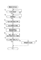
- FIG. 4 is a flowchart illustrating an example of a procedure for calibrating the current sensor 2a.
- the flowchart shown in FIG. 4 shows a calibration procedure for one current sensor 2a, and the other current sensors 2a are also calibrated by the same procedure.
- the calibration processing unit 32 of the PLC slave unit 3 determines whether or not it is a predetermined time set in advance as a timing at which the current sensor 2a should be calibrated (step S1).
- the predetermined time for example, calibration can be performed once a day, or can be arbitrarily set once every few days or once a month. Further, when the current sensor 2a is replaced, the predetermined time can be set immediately after the replacement of the current sensor 2a.
- step S1 If it is determined in step S1 that it is not the predetermined time, the calibration processing unit 32 returns to step S1 again. Therefore, the calibration processing unit 32 repeats the determination in step S1 until it is determined as the predetermined time. If it determines with it being a predetermined time in step S1, the calibration process part 32 will progress to step S2, and will determine whether the string S has stopped electric power generation (step S2). The calibration processing unit 32 determines whether or not the string S has stopped power generation by referring to the current value information generated by the data generation unit 31 and corrected by the calibration processing unit 32.
- step S2 If it is determined in step S2 that the string S has not stopped power generation, the calibration processing unit 32 returns to step S2 again. Therefore, the calibration processing unit 32 repeats the determination in step S2 until it is determined that the string S has stopped generating power.
- step S2 If it is determined in step S2 that the string S has stopped generating power, the calibration processing unit 32 includes current value information (first current value information) indicating the current current value among the current value information provided from the data generation unit 31. ) Is acquired (step S3). At this time, since the string S has stopped generating power, the current value is almost “0”.
- the calibration processing unit 32 causes the current supply unit 34 to supply a calibration current (step S4), and current value information (second current) indicating a current value when the calibration current is supplied to the calibration circuit 20. Value information) is acquired (step S5).
- the calibration processing unit 32 that has acquired the first current value information and the second current value information obtains a difference between the both current value information, and obtains and updates a correction coefficient based on the difference (step S6). More specifically, the calibration processing unit 32 compares the difference with the current value of the calibration current, and obtains the ratio of the difference with respect to the current value of the calibration current. Next, the reciprocal of the ratio is obtained, and this reciprocal is obtained as a correction coefficient.
- the difference indicates a result of measuring the current value of the calibration current by the current sensor 2a on the basis of the current value indicated by the first current value information when the calibration current is not supplied.
- the current value indicated by the first current value information measured by the current sensor 2a when the calibration current is not supplied to the calibration circuit 20 is substantially “0”. It is. Therefore, the current value indicated by the second current value information measured by the current sensor 2a when the calibration current is supplied to the calibration circuit 20 indicates the difference, and only the calibration current flows. It can be said that the current value is shown. Therefore, the difference between the difference and the current value of the calibration current becomes an error included in the actual current value and the current value information obtained from the sensor output of the current sensor 2a.
- the calibration processing unit 32 obtains the difference between the first current value information and the second current value information. The result of measuring the current value of the calibration current by the current sensor 2a can be obtained.
- the correction coefficient is “1.11”. That is, the current value information obtained from the sensor output of the current sensor 2a indicates a value of 90% of the true value. By multiplying this current value information by the correction coefficient 1.11, the current value information is obtained from the sensor output. Errors contained in the obtained current value information can be suppressed, and the accuracy can be maintained.
- the calibration processing unit 32 obtains and updates the correction coefficient capable of suppressing the error included in the current value information that is the output of the current sensor 2a in step S6. Thereby, the accuracy of the current value information, which is information indicating the current value measured by the current sensor 2a, is maintained, and the current sensor 2a is calibrated.
- the calibration circuit 20, the current supply unit 34, and the calibration processing unit 32 constitute a configuration system for calibrating the current sensor 2a that measures the generated current of the string S.
- the abnormality detection unit 33 determines that the correction coefficient obtained by the calibration processing unit 32 is not less than the preset lower limit value Th L and not more than the upper limit value Th U. It is determined whether or not there is (step S7).
- step S7 If it is determined in step S7 that the correction coefficient is not less than the lower limit value Th L and not more than the upper limit value Th U , the abnormality detection unit 33 ends the process. On the other hand, if it is determined in step S7 that the correction coefficient is not less than the lower limit value Th L and not more than the upper limit value Th U (the correction coefficient is smaller than the lower limit value Th L or larger than the upper limit value Th U ), the abnormality detection unit 33. Proceeds to step S8, transmits the above-described abnormality notification to the PLC master unit 9 (step S8), and ends the process.
- the lower limit value Th L is set to a value with which it can be determined that an abnormality has occurred in the current sensor 2a when the correction coefficient is smaller than the lower limit value Th L.
- the upper limit value Th U is set to a value with which it can be determined that an abnormality has occurred in the current sensor 2a when the correction coefficient is larger than the upper limit value Th U. Therefore, the abnormality detection unit 33, by comparing the correction factor, and a lower limit value Th L and an upper limit Th U, it is possible to detect the abnormality of the current sensor 2a.
- the current value output from the current sensor 2a is different from the assumed value
- the current value output from the current sensor 2a is assumed unless the abnormality detection unit 33 detects an abnormality in the current sensor 2a. It can be determined that the cause of the different value from the existing value exists in the string S.
- the abnormality detection part 33 since the abnormality detection part 33 is provided, when the electric current value which the electric current sensor 2a outputs becomes a value different from the assumed value, is abnormality having arisen in the electric current sensor 2a? It is possible to determine whether an abnormality has occurred in the string S.
- the present embodiment is a calibration system that calibrates the current sensor 2a that measures the generated current of the string S, and the current sensor 2a measures the current value of the output electric circuit L for outputting the generated power of the string S.
- a calibration circuit 20 arranged so that a current value is measured by the current sensor 2a together with the output circuit L, and a current supply unit 34 for supplying a calibration current having a predetermined current value to the calibration circuit 20; First current value information measured by the current sensor 2a when no calibration current is supplied to the calibration circuit 20, and measured by the current sensor 2a when calibration current is supplied to the calibration circuit 20.
- a calibration processing unit 32 that calibrates the current sensor 2a based on the difference from the second current value information.
- the calibration circuit 20 if the calibration circuit 20 is provided and a calibration current having a predetermined current value is supplied to the calibration circuit 20, a difference between the first current value information and the second current value information can be obtained.
- the correction coefficient can be obtained by comparing this difference with the current value of the calibration current. As a result, the current sensor can be easily calibrated.
- a plurality of strings S are connected to one junction box 4, and a plurality of current sensors 2a are also provided corresponding to the plurality of strings S. It arrange
- the calibration processing unit 32 is configured to calibrate the current sensor 2a when the string S stops generating power.
- the current value information and the second current value information do not include the current value of the generated current by the string S. Therefore, the difference between the first current value information and the second current value information is not affected by the current value of the generated current by the string S.
- the calibration processing unit 32 can calibrate using the difference obtained based only on the calibration current supplied to the calibration circuit 20. For this reason, for example, it is possible to perform calibration more accurately without being affected by fluctuations in current other than calibration current, such as power generation current generated by the string S.
- the current sensor 2a detects the magnetic flux generated in the ferrite core 15 that is an annular member and the current flowing through the output electric path L and outputs a signal that represents the current value of the flowing current. Hall element 16 is provided.
- the calibration circuit 20 is disposed inside the ferrite core 15 together with the output circuit L, the calibration circuit 20 can be measured by the current sensor 2a together with the output circuit L with a simple configuration. 20 can be arranged.
- the present invention is not limited to the above embodiment.
- the case where the calibration processing unit 32 and the abnormality detection unit 33 are provided in the PLC slave unit 3 is exemplified.
- the calibration processing unit 92 and the abnormality detection unit are included in the PLC master unit 9. 93 may be provided.
- the data generation unit 31 of the PLC slave unit 3 generates current value information and voltage value information obtained from the sensor outputs of the sensors 2a and 2v, and transmits them to the PLC master unit 9 by power line communication.
- the calibration processing unit 92 of the PLC master unit 9 that has received the current value information transmitted from the PLC slave unit 3 multiplies the current value information by a correction coefficient in the same manner as the calibration processing unit 32 described in the above embodiment. Then, the correction is made so that the error is suppressed, the correction coefficient is updated, and the current sensor 2a is calibrated. Moreover, the abnormality detection part 93 performs the process which detects abnormality of the current sensor 2a with the correction coefficient which the calibration process part 92 calculates
- the processing can be shared between the PLC slave unit 3 and the PLC master unit 9, and the mutual load state can be made appropriate.
- the circuit 20 for a calibration was arrange
- FIG. the current value of the calibration current measured by the current sensor 2a can be increased without passing a large current as the calibration current. As a result, error detection becomes easier and calibration can be performed with higher accuracy.
- the sensor 2a can be calibrated.
- the first current value information measured when the calibration current is not supplied and the calibration current is supplied to the calibration circuit 20 The difference from the second current value information measured in (2) is less influenced by the generated current of the string S. Therefore, when the generated power of the string S is stable, the current sensor 2a may be calibrated even when the string S is generating power.
- the current sensor 2a can be calibrated. Further, in this case, it is preferable to measure the first current value information when the calibration current is not supplied immediately before or immediately after the measurement of the second current value information when the calibration current is supplied. . As a result, the state of the generated power of the string S can be prevented from changing between when the calibration current is supplied and when the calibration current is not supplied, and the calibration is performed more accurately. It can be performed.
Landscapes
- Physics & Mathematics (AREA)
- General Physics & Mathematics (AREA)
- Measurement Of Current Or Voltage (AREA)
- Photovoltaic Devices (AREA)
Abstract
校正システムは、出力電路Lとともに電流センサ2aによって電流値が計測されるように配置される校正用電路20と、校正用電路20に所定電流値の校正用電流を供給する電流供給部34と、校正用電路20に校正用電流が供給されていないときに電流センサ2aによって計測された第1電流値情報と、校正用電路20に校正用電流が供給されたときに電流センサ2aによって計測された第2電流値情報との差分に基づいて電流センサ2aを校正する校正処理部32とを備えている。
Description
本発明は、太陽光発電システムに用いられる電流センサを校正するための校正システム、太陽光発電用監視システム、及び校正方法に関する。
太陽光発電では、所定の大きさの太陽光発電パネルを多数並べて、これらの出力を接続箱で集約する構成が採られる。また例えば、いわゆるメガソーラー(大規模太陽光発電所)では、複数の太陽光発電パネルを接続してなるストリングを多数設け、これらストリングを接続箱に接続することで、各ストリングの出力を集約し電力変換装置に送り込むように構成されることがある。
これら多数のストリングに異常が生じていないかを監視するために、各ストリングが出力する電流・電圧をセンサによって計測し、ストリングごとの計測データを収集することができる監視システムが提案されている(例えば、特許文献1参照)。
上記監視システムでは、ストリングが出力する発電量を、当該発電量を計測するためのセンサの出力に基づいて監視しているため、このセンサの精度が低下するとストリングの発電量を正確に把握できず、適切な監視ができなくなるおそれがある。
さらに、センサの精度低下によって、センサ出力による計測結果と、実際の発電量との間に大きな差が生じると、ストリングに異常が生じているのか、センサに異常が生じているのかを判断することができない場合も生じる。
一方、センサの精度を維持するために定期的にセンサの校正を行うことが考えられるが、多数のストリングを備えている場合には、各ストリングに設けられたセンサについて個別に校正を行わなければならず、校正の作業が煩雑となる場合があった。
本発明はこのような事情に鑑みてなされたものであり、太陽光発電システムに用いられる電流センサを容易に校正することができる校正システム、太陽光発電用監視システム及び校正方法を提供することを目的とする。
一実施形態である校正システムは、太陽光発電パネルの発電電流を計測する電流センサを校正する校正システムであって、前記電流センサは、前記太陽光発電パネルの発電電力を出力するための出力電路の電流値を計測するように構成され、前記出力電路とともに前記電流センサによって電流値が計測されるように配置される校正用電路と、前記校正用電路に所定電流値の校正用電流を供給する供給部と、前記校正用電路に前記校正用電流が供給されていないときに前記電流センサによって計測された第1電流値と、前記校正用電路に前記校正用電流が供給されたときに前記電流センサによって計測された第2電流値との差分に基づいて前記電流センサを校正する校正処理部と、を備えている。
また、一実施形態である太陽光発電用監視システムは、太陽光発電パネルの状態を監視する太陽光発電用監視システムであって、前記太陽光発電パネルの発電電流を計測する電流センサと、上述の校正システムと、を備えている。
また、一実施形態である校正方法は、太陽光発電パネルの発電電流を計測する電流センサであって前記太陽光発電パネルを出力するための出力電路の電流値を計測するように構成されている電流センサを校正する校正方法であって、前記出力電路とともに前記電流センサによって電流値が計測されるように配置される校正用電路に所定電流値の校正用電流を供給する供給ステップと、前記校正用電路に前記校正用電流が供給されていないときに前記電流センサによって計測された第1電流値と、前記校正用電路に前記校正用電流が供給されたときに前記電流センサによって計測された第2電流値との差分に基づいて前記電流センサを校正する校正処理ステップと、を備えている。
なお、上記各実施形態は、上記システム及び方法として実現できるだけでなく、上述の各機能部が行う処理をステップとしたコンピュータに実行させるためのプログラムとして実現したりすることができる。
本発明によれば、太陽光発電システムに用いられる電流センサを容易に校正することができる。
[本願発明の実施形態の説明]
まず最初に本願発明の実施形態の内容を列記して説明する。
(1)一実施形態である校正システムは、太陽光発電パネルの発電電流を計測する電流センサを校正する校正システムであって、前記電流センサは、前記太陽光発電パネルの発電電力を出力するための出力電路の電流値を計測するように構成され、前記出力電路とともに前記電流センサによって電流値が計測されるように配置される校正用電路と、前記校正用電路に所定電流値の校正用電流を供給する供給部と、前記校正用電路に前記校正用電流が供給されていないときに前記電流センサによって計測された第1電流値と、前記校正用電路に前記校正用電流が供給されたときに前記電流センサによって計測された第2電流値との差分に基づいて前記電流センサを校正する校正処理部と、を備えている。
まず最初に本願発明の実施形態の内容を列記して説明する。
(1)一実施形態である校正システムは、太陽光発電パネルの発電電流を計測する電流センサを校正する校正システムであって、前記電流センサは、前記太陽光発電パネルの発電電力を出力するための出力電路の電流値を計測するように構成され、前記出力電路とともに前記電流センサによって電流値が計測されるように配置される校正用電路と、前記校正用電路に所定電流値の校正用電流を供給する供給部と、前記校正用電路に前記校正用電流が供給されていないときに前記電流センサによって計測された第1電流値と、前記校正用電路に前記校正用電流が供給されたときに前記電流センサによって計測された第2電流値との差分に基づいて前記電流センサを校正する校正処理部と、を備えている。
上記のように構成された校正システムによれば、校正用電路を設けておき、この校正用電路に所定電流値の校正用電流を供給すれば、第1電流値及び第2電流値の差分を得ることができ、この差分と、校正用電流の電流値とを比較することで、電流センサを容易に校正することができる。
(2)上記校正システムにおいて、前記太陽光パネル及び前記電流センサは複数であり、 前記校正用電路は、一の電路によって複数の前記電流センサによる電流値の計測がなされるように配置されていることが好ましい。
この場合、太陽光パネル及び電流センサが複数であったとしても、校正用電路に所定電流値の校正用電流を供給すれば、複数の電流センサそれぞれに校正用電流を供給でき、校正を行うことができる。よって、各電流センサを個別に校正する必要がなく、容易に複数の電流センサについて校正することができる。
この場合、太陽光パネル及び電流センサが複数であったとしても、校正用電路に所定電流値の校正用電流を供給すれば、複数の電流センサそれぞれに校正用電流を供給でき、校正を行うことができる。よって、各電流センサを個別に校正する必要がなく、容易に複数の電流センサについて校正することができる。
(3)また、上記校正システムにおいて、前記校正処理部は、前記太陽光発電パネルが発電していないときに計測された前記第1電流値と、前記太陽光発電パネルが発電していないときに計測された前記第2電流値との差分に基づいて前記電流センサを校正してもよい。
この場合、校正処理部は、ほぼ校正用電路に供給される校正用電流に基づいて得られた差分を用いて校正することができる。このため、校正用電流以外の電流の変動等による影響を受けることがなく、より精度よく校正することができる。
この場合、校正処理部は、ほぼ校正用電路に供給される校正用電流に基づいて得られた差分を用いて校正することができる。このため、校正用電流以外の電流の変動等による影響を受けることがなく、より精度よく校正することができる。
(4)上記校正システムにおいて、前記校正処理部による校正結果に基づいて、前記電流センサの異常を検知する異常検知部をさらに備えていてもよく、この場合、例えば、電流センサが出力する電流値が想定される値と異なる値となる場合に、電流センサに異常が生じているのか、太陽光発電パネルに異常が生じているのかを判断することができる。
(5)また、前記電流センサが、前記出力電路が内側に配置され当該出力電路に電流が流れることで磁束を生じさせる環状部材と、生じた磁束を検出し流れる電流の電流値を表す信号を出力する検出部とを備えている場合、前記校正用電路は、前記出力電路とともに前記環状部材の内側に配置されていることが好ましい。
この場合、簡易な構成で、出力電路とともに電流センサによって電流値の計測がなされるように校正用電路を配置することができる。
この場合、簡易な構成で、出力電路とともに電流センサによって電流値の計測がなされるように校正用電路を配置することができる。
(6)また、一実施形態である太陽光発電用監視システムは、太陽光発電パネルの状態を監視する太陽光発電用監視システムであって、前記太陽光発電パネルの発電電流を計測する電流センサと、上記(1)に記載の校正システムと、
を備えている。
を備えている。
(7)また、一実施形態である校正方法は、太陽光発電パネルの発電電流を計測する電流センサであって前記太陽光発電パネルを出力するための出力電路の電流値を計測するように構成されている電流センサを校正する校正方法であって、前記出力電路とともに前記電流センサによって電流値が計測されるように配置される校正用電路に所定電流値の校正用電流を供給する供給ステップと、前記校正用電路に前記校正用電流が供給されていないときに前記電流センサによって計測された第1電流値と、前記校正用電路に前記校正用電流が供給されたときに前記電流センサによって計測された第2電流値との差分に基づいて前記電流センサを校正する校正処理ステップと、を備えている。
上記のように構成された太陽光発電用監視システム及び校正方法によれば、太陽光発電システムに用いられる電流センサを容易に校正することができる。
なお、上記各実施形態は、上記校正システム、及び太陽光発電用監視システムとして実現できるだけでなく、上述の各機能部が行う処理をステップとしたコンピュータに実行させるためのプログラムとして実現したりすることができる。
[本願発明の実施形態の詳細]
以下、好ましい実施形態について図面を参照しつつ説明する。
〔1.システムの全体構成について〕
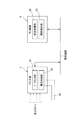
図1は、太陽光発電用監視システムの全体構成例を示す単線系統図である。なお、図示している各要素や各構成の個数は一例に過ぎない。
図において、当該システムは、1つの集電系統P1を備えている。集電系統P1において、多数の太陽光発電パネル1の直流出力は、所定数ごとにそれぞれ、複数の接続箱4(図例では4つ)に集約される。また、4つの接続箱4からさらに上位の集電箱5に、出力が集約される。集電箱5からの出力は、電力変換装置7で交流に変換され、変圧器11を介して商用電力系統に交流電力を提供することができる。
以下、好ましい実施形態について図面を参照しつつ説明する。
〔1.システムの全体構成について〕
図1は、太陽光発電用監視システムの全体構成例を示す単線系統図である。なお、図示している各要素や各構成の個数は一例に過ぎない。
図において、当該システムは、1つの集電系統P1を備えている。集電系統P1において、多数の太陽光発電パネル1の直流出力は、所定数ごとにそれぞれ、複数の接続箱4(図例では4つ)に集約される。また、4つの接続箱4からさらに上位の集電箱5に、出力が集約される。集電箱5からの出力は、電力変換装置7で交流に変換され、変圧器11を介して商用電力系統に交流電力を提供することができる。
上記の各接続箱4は、各接続箱4に繋がっている太陽光発電パネル1の発電電力(電流・電圧)を測定するセンサやその測定結果を示す情報を送信する電力線通信用の子機(以下、PLC(Power Line Communication)子機ともいう)を備えている(詳細後述)。
集電箱5から電力変換装置7に至る直流電路には、電力線通信用の親機(以下、PLC親機ともいう)9が接続されている。PLC親機9は、前記PLC子機から電力線通信によって送信される情報を受信し取得する。
また、PLC親機9は、例えばLAN(Local Area Network)配線を介して監視装置10と接続されている。PLC親機9は、電力変換装置7と共に、パワーコンディショナPC1に搭載されている。
また、PLC親機9は、例えばLAN(Local Area Network)配線を介して監視装置10と接続されている。PLC親機9は、電力変換装置7と共に、パワーコンディショナPC1に搭載されている。
なお、PLC親機9は、必ずしもパワーコンディショナPC1の内部に搭載されていなくてもよく、パワーコンディショナPC1の周辺にあってもよい。要するに、集電系統P1の集電終端(電力変換装置7の入力側)に付随して、PLC親機9が設けられていればよい。但し、ここでは、パワーコンディショナPC1の内部にPLC親機9が設けられているものとして説明する。
図2は、複数の太陽光発電パネル1、及び太陽光発電パネル1が接続された接続箱4の構成の一例を示す回路図である。
図2において、接続箱4に接続されている複数の太陽光発電パネル1は、複数のストリングSを構成している。
ストリングSは、所定数の太陽光発電パネル1を例えば直並列に接続されることで構成されており、接続箱4に複数の太陽光発電パネル1を接続するためのユニットを構成している。接続箱4には、複数のストリングSが並列に接続されており、各ストリングSの発電電力を集約する。
図2において、接続箱4に接続されている複数の太陽光発電パネル1は、複数のストリングSを構成している。
ストリングSは、所定数の太陽光発電パネル1を例えば直並列に接続されることで構成されており、接続箱4に複数の太陽光発電パネル1を接続するためのユニットを構成している。接続箱4には、複数のストリングSが並列に接続されており、各ストリングSの発電電力を集約する。
接続箱4の内部には、各ストリングSに対応して出力される電流及び電圧をそれぞれ計測する電流センサ2a及び電圧センサ2vが設けられている。電流センサ2aは、接続箱4とストリングSとを繋いでいる電路に流れる電流を測定する。また、電圧センサ2vは、接続箱4とストリングSとを繋いでいる電路の電圧を測定する。
電流センサ2a及び電圧センサ2vは、計測した電流値及び電圧値を示す情報をセンサ出力として出力する。電流センサ2a及び電圧センサ2vのセンサ出力が示す電流値及び電圧値に基づいて、対応するストリングSの発電量としての発電電力値が求められる。
なお、電圧の変化は少ないので、電流センサ2aが計測する電流値を、対応するストリングSの発電量と考えることもできる。
なお、電圧の変化は少ないので、電流センサ2aが計測する電流値を、対応するストリングSの発電量と考えることもできる。
さらに、接続箱4の内部には、前述のPLC子機3が設けられている。PLC子機3には、電流センサ2a及び電圧センサ2vのセンサ出力が与えられる。
PLC子機3は、電流センサ2aによる測定結果を示すセンサ出力及び電圧センサ2vによる測定結果を示すセンサ出力を収集し、センサ2a、2vによるセンサ出力に基づいて当該センサ2a、2vに対応するストリングSの電流値情報及び電圧値情報を生成する。
PLC子機3は、電流センサ2aによる測定結果を示すセンサ出力及び電圧センサ2vによる測定結果を示すセンサ出力を収集し、センサ2a、2vによるセンサ出力に基づいて当該センサ2a、2vに対応するストリングSの電流値情報及び電圧値情報を生成する。
PLC子機3は、生成したストリングSの電流値情報及び電圧値情報を電力線通信によってPLC親機9に送信する。
また、PLC子機3は、電流センサ2aについての校正を実行する機能を有するとともに、電流センサ2aの異常の有無を検知する機能を有している。この点については、後に詳述する。
また、PLC子機3は、電流センサ2aについての校正を実行する機能を有するとともに、電流センサ2aの異常の有無を検知する機能を有している。この点については、後に詳述する。
なお、PLC子機3は、必ずしも接続箱4の内部に設けられていなくてもよく、接続箱4の周辺にあってもよい。要するに、接続箱4に付随して、PLC子機3が設けられていればよい。但し、ここでは、接続箱4の内部にPLC子機3が設けられているものとして説明する。
PLC子機3は、直流電路LP,LNに接続されており、ストリングSの電流値情報及び電圧値情報を、直流電路LP,LNに載せて電力線通信により送信する。この電力線通信による送信信号は、上位の集電箱5(図1)を介して集電終端である電力変換装置7の入力側にまで届く。
このように、PLC子機3が送信する電圧値情報及び電圧値情報は、接続箱4から出力され、集電箱5を通過して、電力変換装置7の入力側にまで到達し、PLC親機9(図1)に与えられる。
さらに、電圧値情報及び電圧値情報は、PLC親機9から監視装置10に与えられる。
監視装置10は、PLC子機3から与えられる電圧値情報及び電圧値情報に基づいて各ストリングS(太陽光発電パネル1)の電流値及び電圧値を認識し、各ストリングSを監視する。
さらに、電圧値情報及び電圧値情報は、PLC親機9から監視装置10に与えられる。
監視装置10は、PLC子機3から与えられる電圧値情報及び電圧値情報に基づいて各ストリングS(太陽光発電パネル1)の電流値及び電圧値を認識し、各ストリングSを監視する。
〔2.校正システムについて〕
図3は、接続箱4内における、電流センサ2a及びPLC子機の詳細を示した図であり、電流センサ2aの校正を実行する校正システムの構成を示している。なお、複数のストリングSは、接続箱4にn個接続されており、図3においては、複数のストリングSの図示を省略し、複数のストリングSから延びている発電電力を出力するための出力電路Lを示している。なお、図3では、複数のストリングSを紙面上方から順にストリングS1、S2、S3・・・Sn、対応する出力電路Lを紙面上方から順に出力電路L1、L2、L3・・・Lnと示している。
また、以下の説明では、ストリングS1の発電電流が流れる出力電路L1に設けられた電流センサ2aに着目して説明するが、他の電流センサ2aも同様の構成である。
図3は、接続箱4内における、電流センサ2a及びPLC子機の詳細を示した図であり、電流センサ2aの校正を実行する校正システムの構成を示している。なお、複数のストリングSは、接続箱4にn個接続されており、図3においては、複数のストリングSの図示を省略し、複数のストリングSから延びている発電電力を出力するための出力電路Lを示している。なお、図3では、複数のストリングSを紙面上方から順にストリングS1、S2、S3・・・Sn、対応する出力電路Lを紙面上方から順に出力電路L1、L2、L3・・・Lnと示している。
また、以下の説明では、ストリングS1の発電電流が流れる出力電路L1に設けられた電流センサ2aに着目して説明するが、他の電流センサ2aも同様の構成である。
図中、電流センサ2aは、環状部材であるフェライトコア15と、ホール素子16とを有して構成されている。
フェライトコア15は、ストリングS1が発電する発電電力を出力するための出力電路L1の外周側に配置されている。フェライトコア15は、C字型に形成されており、周方向の一部にはエアギャップが設けられている。
ホール素子16は、フェライトコア15のエアギャップに配置されており、このエアギャップにおける磁束密度に応じた電圧信号をセンサ出力として出力する。
フェライトコア15は、ストリングS1が発電する発電電力を出力するための出力電路L1の外周側に配置されている。フェライトコア15は、C字型に形成されており、周方向の一部にはエアギャップが設けられている。
ホール素子16は、フェライトコア15のエアギャップに配置されており、このエアギャップにおける磁束密度に応じた電圧信号をセンサ出力として出力する。
電流センサ2aは、フェライトコア15の内側に配置される出力電路L1に電流が流れたときに当該フェライトコア15に生じる磁束をホール素子16によって検出し、検出した磁束を電圧に変換してセンサ出力としてPLC子機3に出力する。
フェライトコア15に生じる磁束密度は、出力電路L1に流れる電流の電流値に応じて変化する。ホール素子16は、上述のように、エアギャップにおける磁束密度に応じた電圧信号をセンサ出力として出力する。よって、電流センサ2aが出力電路L1の電流によって生じる磁束を検出して出力するセンサ出力は、出力電路L1に流れる電流値を示している。
フェライトコア15に生じる磁束密度は、出力電路L1に流れる電流の電流値に応じて変化する。ホール素子16は、上述のように、エアギャップにおける磁束密度に応じた電圧信号をセンサ出力として出力する。よって、電流センサ2aが出力電路L1の電流によって生じる磁束を検出して出力するセンサ出力は、出力電路L1に流れる電流値を示している。
また、本実施形態の電流センサ2aのフェライトコア15の内側には、電流センサ2aを校正するために用いられる校正用電路20が挿通されている。
校正用電路20は、出力電路L1とともにフェライトコア15の内側に挿通されており、出力電路L1とともに電流センサ2aによって当該校正用電路20を流れる電流の電流値が計測されるように配置されている。
校正用電路20は、出力電路L1とともにフェライトコア15の内側に挿通されており、出力電路L1とともに電流センサ2aによって当該校正用電路20を流れる電流の電流値が計測されるように配置されている。
校正用電路20は、一の電路によって構成されており、各ストリングSに対応して設けられている各電流センサ2aのフェライトコア15の内側を通過して配置されている。つまり、校正用電路20は、一の電路によって各電流センサ2aによる電流の計測がなされるように配置されている。
校正用電路20は、PLC子機3に接続されており、後述するようにPLC子機3から直流電流である校正用電流が供給される。
校正用電路20は、PLC子機3から供給される校正用電流が、各ストリングSから延びている出力電路L1、L2・・Lnにおける電流の流れる方向と一致する方向に流れるように配置されている。
校正用電路20は、PLC子機3から供給される校正用電流が、各ストリングSから延びている出力電路L1、L2・・Lnにおける電流の流れる方向と一致する方向に流れるように配置されている。
電流センサ2aは、フェライトコア15の内側に出力電路L1とともに校正用電路20が配置されているため、出力電路L1に電流が供給されたときの磁束とともに校正用電路20に電流が供給されたときの磁束も検出する。
よって、電流センサ2aは、出力電路L1に流れる電流と、校正用電路20に流れる電流とを合わせた電流値を計測することができる。
よって、電流センサ2aは、出力電路L1に流れる電流と、校正用電路20に流れる電流とを合わせた電流値を計測することができる。
つまり、電流センサ2aは、出力電路L1のみに電流が流れていれば、出力電路L1に流れる電流の電流値を計測する。また、電流センサ2aは、校正用電路20のみに電流が流れていれば、校正用電路20に流れる電流の電流値を計測する。
さらに、電流センサ2aは、出力電路L1と校正用電路20の両方に電流が流れていれば、両電路L1、20に流れる電流の合計の電流値を計測する。
さらに、電流センサ2aは、出力電路L1と校正用電路20の両方に電流が流れていれば、両電路L1、20に流れる電流の合計の電流値を計測する。
PLC子機3は、電力線通信を実行する機能部の他、プロセッサやROM、RAM等や、記憶部とを備えたマイコンを備えて構成されている。記憶部には、PLC子機3が有する機能を実現するための各種コンピュータプログラムが記憶されている。PLC子機3は、これらコンピュータプログラムを実行することで、必要な各機能や、後述する機能部を実現する。
PLC子機3は、データ生成部31と、校正処理部32と、異常検知部33と、電流供給部34とを機能的に有している。
データ生成部31は、電流センサ2a及び電圧センサ2vから与えられるセンサ出力を収集し、センサ2a、2vによるセンサ出力に基づいて当該センサ2a、2vに対応するストリングSの電流値情報及び電圧値情報といった計測データに関する情報を生成する。
データ生成部31は、電流センサ2a及び電圧センサ2vから与えられるセンサ出力を収集し、センサ2a、2vによるセンサ出力に基づいて当該センサ2a、2vに対応するストリングSの電流値情報及び電圧値情報といった計測データに関する情報を生成する。
データ生成部31は、一定の期間(例えば、1分)ごとにセンサ2a、2vのセンサ出力を取得し、電流値情報及び電圧値情報を生成する。従って、電流値情報及び電圧値情報は、前記一定の期間ごとの電流値及び電圧値を示す情報として継続的に生成される。
データ生成部31は、生成した情報の内、電流値情報を校正処理部32に与える。
データ生成部31は、生成した情報の内、電流値情報を校正処理部32に与える。
校正処理部32は、データ生成部31から与えられた電流値情報に対して補正を行い、補正後の電流値情報を出力する。
校正処理部32は、下記式に基づいて、データ生成部31から与えられる電流値情報から補正後の電流値情報を求める。
補正後の電流値情報 =
データ生成部31から与えられる電流値情報 × 補正係数
校正処理部32は、下記式に基づいて、データ生成部31から与えられる電流値情報から補正後の電流値情報を求める。
補正後の電流値情報 =
データ生成部31から与えられる電流値情報 × 補正係数
電流センサ2aのセンサ出力から得られる電流値情報は、出力電路L1の電流値を示しているが、電流センサ2aの個体差や配置状態の違い、さらに各部の経時的な変化によって誤差を含む場合がある。
このため、校正処理部32は、電流センサ2aの精度を維持するために、上記式に示すように、データ生成部31から与えられる電流値情報に補正係数を乗算することで上記誤差が抑圧されるように補正する。
このため、校正処理部32は、電流センサ2aの精度を維持するために、上記式に示すように、データ生成部31から与えられる電流値情報に補正係数を乗算することで上記誤差が抑圧されるように補正する。
なお、前記補正係数は、センサ出力に乗算することで、電流センサ2aにより計測された電流値情報に含まれる誤差が抑圧されるように設定された数値であり、後述するように、校正処理部32によって適宜更新される。
電流センサ2aは、校正処理部32による電流値情報に対する補正によって、電流センサとしての精度を維持することができる。
PLC子機3は、補正後の電流値情報を電流センサ2aが計測した電流値を示す情報として、電圧値情報とともに電力線通信によってPLC親機9に送信する。
また、校正処理部32は、電流センサ2aのセンサ出力から得られる電流値情報に含まれる誤差を検出し、検出した誤差に基づいて前記補正係数を更新する機能を有している。
上述したように、電流センサ2aのセンサ出力から得られる電流値情報は、誤差を含んでおり、これを抑圧するために校正処理部32は電流値情報に対して補正を行う一方、経時的に変化する誤差によって、過去に求めた補正係数では、電流値情報に含まれる誤差を効果的に抑圧できなくなることがある。
さらに、電流センサ2aそのものを交換した場合には、交換前の電流センサ2aの補正係数と、交換後の電流センサ2aとの間に個体差があるため、補正係数が異なる場合がある。この場合にも、現状の補正係数では、電流値情報に含まれる誤差を効果的に抑圧できなくなる。
さらに、電流センサ2aそのものを交換した場合には、交換前の電流センサ2aの補正係数と、交換後の電流センサ2aとの間に個体差があるため、補正係数が異なる場合がある。この場合にも、現状の補正係数では、電流値情報に含まれる誤差を効果的に抑圧できなくなる。
このような場合、校正処理部32は、電流センサ2aにより計測された電流値情報に含まれる誤差を検出し、この検出した誤差を抑圧可能な新たな補正係数を求めて更新する。
校正処理部32は、新たな補正係数に更新することで、経時的に生じた誤差を効果的に抑圧し、電流センサ2aが計測した電流値を示す情報である補正後の電流値情報の精度を維持する。
つまり、校正処理部32は、適宜、前記補正係数を更新することで、電流センサ2aの出力精度を維持しており、前記補正係数の更新によって電流センサ2aの校正を行っている。
つまり、校正処理部32は、適宜、前記補正係数を更新することで、電流センサ2aの出力精度を維持しており、前記補正係数の更新によって電流センサ2aの校正を行っている。
異常検知部33は、校正処理部32が行う校正の結果として求められる補正係数に基づいて、電流センサ2aの異常を検知する機能を有している。
補正係数が極端に大きい値であったり小さい値であったりすると、電流センサ2aに異常が生じている場合がある。よって、電流センサ2aに異常が生じていると判断できる閾値を予め設定し、補正係数とこの閾値とを比較することで、電流センサ2aに異常が生じているか否かを判断することができる。
補正係数が極端に大きい値であったり小さい値であったりすると、電流センサ2aに異常が生じている場合がある。よって、電流センサ2aに異常が生じていると判断できる閾値を予め設定し、補正係数とこの閾値とを比較することで、電流センサ2aに異常が生じているか否かを判断することができる。
そこで、異常検知部33は、補正係数と、電流センサ2aに異常が生じていると判断することができる閾値とを比較して電流センサ2aの異常を検知する。
また、異常検知部33は、電流センサ2aの異常を検知すると、電力線通信によって、電流センサ2aに異常が生じていることを示す異常通知をPLC親機9(図1)に送信する。
この異常通知には、複数のストリングSの内、どのストリングSの電流センサ2aに異常が生じているかを示す情報が含まれている。
また、異常検知部33は、電流センサ2aの異常を検知すると、電力線通信によって、電流センサ2aに異常が生じていることを示す異常通知をPLC親機9(図1)に送信する。
この異常通知には、複数のストリングSの内、どのストリングSの電流センサ2aに異常が生じているかを示す情報が含まれている。
異常通知は、PLC親機9を通じて監視装置10に与えられる。
監視装置10は、異常通知が与えられると、電流センサ2aに異常が検知されたことを、その電流センサ2aを特定するための情報とともに出力し、当該監視装置10のオペレータ等に報知する。
監視装置10は、異常通知が与えられると、電流センサ2aに異常が検知されたことを、その電流センサ2aを特定するための情報とともに出力し、当該監視装置10のオペレータ等に報知する。
電流供給部34は、校正用電路20に所定の電流値に設定された直流電流である校正用電流を供給する機能を有している。電流供給部34は、校正処理部32の制御に基づいて、必要なときに校正用電流を供給する。
〔3.電流センサの校正の手順について〕
図4は、電流センサ2aを校正する際の手順の一例を示すフローチャートである。なお、図4に示すフローチャートは、一の電流センサ2aに対する校正の手順を示しており、他の電流センサ2aについても同様の手順によって校正される。
図4は、電流センサ2aを校正する際の手順の一例を示すフローチャートである。なお、図4に示すフローチャートは、一の電流センサ2aに対する校正の手順を示しており、他の電流センサ2aについても同様の手順によって校正される。
まず、PLC子機3の校正処理部32は、電流センサ2aの校正すべきタイミングとして予め設定された所定の時期であるか否かを判定する(ステップS1)。
所定の時期としては、例えば、1日1回校正が行われるように設定することもできるし、数日おきに1回、あるいは1ヵ月に1回と、任意に設定することができる。また、電流センサ2aを交換した場合には、電流センサ2aを交換した直後を所定の時期と設定することもできる。
所定の時期としては、例えば、1日1回校正が行われるように設定することもできるし、数日おきに1回、あるいは1ヵ月に1回と、任意に設定することができる。また、電流センサ2aを交換した場合には、電流センサ2aを交換した直後を所定の時期と設定することもできる。
ステップS1において所定の時期でないと判定すると、校正処理部32は、再度ステップS1に戻る。よって校正処理部32は、所定の時期と判定するまで、ステップS1の判定を繰り返す。
ステップS1において所定の時期であると判定すると、校正処理部32は、ステップS2に進み、ストリングSが発電を停止しているか否かを判定する(ステップS2)。
校正処理部32は、データ生成部31が生成し当該校正処理部32が補正する電流値情報を参照することでストリングSが発電を停止しているか否かを判定する。
ステップS1において所定の時期であると判定すると、校正処理部32は、ステップS2に進み、ストリングSが発電を停止しているか否かを判定する(ステップS2)。
校正処理部32は、データ生成部31が生成し当該校正処理部32が補正する電流値情報を参照することでストリングSが発電を停止しているか否かを判定する。
ステップS2においてストリングSが発電を停止していないと判定すると、校正処理部32は、再度ステップS2に戻る。よって校正処理部32は、ストリングSが発電を停止していると判定するまで、ステップS2の判定を繰り返す。
ステップS2においてストリングSが発電を停止していると判定すると、校正処理部32は、データ生成部31から与えられる電流値情報の内、現状の電流値を示す電流値情報(第1電流値情報)を取得する(ステップS3)。
なお、このとき、ストリングSが発電を停止しているので、現状の電流値は、ほぼ「0」となる。
なお、このとき、ストリングSが発電を停止しているので、現状の電流値は、ほぼ「0」となる。
次いで、校正処理部32は、電流供給部34に校正用電流を供給させ(ステップS4)、校正用電路20に校正用電流が供給されているときの電流値を示す電流値情報(第2電流値情報)を取得する(ステップS5)。
第1電流値情報及び第2電流値情報を取得した校正処理部32は、両電流値情報の差分を求め、この差分に基づいて補正係数を求めて更新する(ステップS6)。
より具体的には、校正処理部32は、前記差分と校正用電流の電流値とを比較し、校正用電流の電流値に対する前記差分の割合を求める。次いで、前記割合の逆数を求め、この逆数を補正係数として求める。
より具体的には、校正処理部32は、前記差分と校正用電流の電流値とを比較し、校正用電流の電流値に対する前記差分の割合を求める。次いで、前記割合の逆数を求め、この逆数を補正係数として求める。
前記差分は、校正用電流が供給されていないときの第1電流値情報が示す電流値を基準として、電流センサ2aによって校正用電流の電流値を計測した結果を示している。
このとき、ストリングSが発電を停止しているので、校正用電路20に校正用電流が供給されていないときに電流センサ2aによって計測された第1電流値情報が示す電流値はほぼ「0」である。よって、校正用電路20に校正用電流が供給されたときに電流センサ2aによって計測された第2電流値情報が示す電流値は、前記差分を示しており、さらに、校正用電流のみが流れたことによる電流値を示しているといえる。
従って、前記差分と校正用電流の電流値との差が、実際の電流値と、電流センサ2aのセンサ出力から得られる電流値情報に含まれる誤差となる。
このとき、ストリングSが発電を停止しているので、校正用電路20に校正用電流が供給されていないときに電流センサ2aによって計測された第1電流値情報が示す電流値はほぼ「0」である。よって、校正用電路20に校正用電流が供給されたときに電流センサ2aによって計測された第2電流値情報が示す電流値は、前記差分を示しており、さらに、校正用電流のみが流れたことによる電流値を示しているといえる。
従って、前記差分と校正用電流の電流値との差が、実際の電流値と、電流センサ2aのセンサ出力から得られる電流値情報に含まれる誤差となる。
なお、ストリングSが発電を停止しているときに、例えば、わずかに電流が流れているとしても、校正処理部32は、第1電流値情報と第2電流値情報との差分を求めるので、電流センサ2aによって校正用電流の電流値を計測した結果を得ることができる。
例えば、前記差分と、校正用電流の電流値とが同じ値であれば、センサ出力から得られる電流値情報に含まれる誤差は無く、電流値情報に対する補正は必要ないので、補正係数は「1」に設定される。
また、前記差分が校正用電流の電流値の90%の値である場合、補正係数は、「1.11」とされる。
つまり、電流センサ2aのセンサ出力から得られる電流値情報は、真値の90%の値を示しているので、この電流値情報に補正係数である1.11を乗算することで、センサ出力から得られる電流値情報に含まれる誤差を抑圧でき、精度を維持することができる。
また、前記差分が校正用電流の電流値の90%の値である場合、補正係数は、「1.11」とされる。
つまり、電流センサ2aのセンサ出力から得られる電流値情報は、真値の90%の値を示しているので、この電流値情報に補正係数である1.11を乗算することで、センサ出力から得られる電流値情報に含まれる誤差を抑圧でき、精度を維持することができる。
以上のようにして校正処理部32は、ステップS6において、電流センサ2aの出力である電流値情報に含まれる誤差を抑圧可能な補正係数を求めて更新する。
これによって、電流センサ2aが計測した電流値を示す情報である電流値情報の精度が維持され、電流センサ2aは校正される。
これによって、電流センサ2aが計測した電流値を示す情報である電流値情報の精度が維持され、電流センサ2aは校正される。
また、上述のように、校正用電路20、電流供給部34、及び校正処理部32は、ストリングSの発電電流を計測する電流センサ2aを校正する構成システムを構成している。
ステップS6において校正処理部32が補正係数の更新を行うと、異常検知部33は、校正処理部32が求めた補正係数が、予め設定された下限値ThL以上でかつ上限値ThU以下であるか否かを判定する(ステップS7)。
ステップS7において、補正係数が下限値ThL以上でかつ上限値ThU以下であると判定すると、異常検知部33は処理を終える。
一方、ステップS7において、補正係数が下限値ThL以上でかつ上限値ThU以下でない(補正係数が下限値ThLより小さく、又は上限値ThUよりも大きい)と判定すると、異常検知部33は、ステップS8に進み、上述の異常通知をPLC親機9に送信し(ステップS8)、処理を終える。
一方、ステップS7において、補正係数が下限値ThL以上でかつ上限値ThU以下でない(補正係数が下限値ThLより小さく、又は上限値ThUよりも大きい)と判定すると、異常検知部33は、ステップS8に進み、上述の異常通知をPLC親機9に送信し(ステップS8)、処理を終える。
ここで、下限値ThLは、補正係数が当該下限値ThLよりも小さい場合に電流センサ2aに異常が生じていると判断することができる値に設定されている。また、上限値ThUは、補正係数が当該上限値ThUよりも大きい場合に電流センサ2aに異常が生じていると判断することができる値に設定されている。
よって、異常検知部33は、補正係数と、下限値ThL及び上限値ThUとを比較することにより、電流センサ2aの異常を検知することができる。
よって、異常検知部33は、補正係数と、下限値ThL及び上限値ThUとを比較することにより、電流センサ2aの異常を検知することができる。
この場合、例えば、電流センサ2aが出力する電流値が想定される値と異なる場合、異常検知部33が電流センサ2aの異常を検出していなければ、電流センサ2aが出力する電流値が想定される値と異なる値となる原因は、ストリングSに存在すると判断することができる。
このように、本実施形態では、異常検知部33を備えているので、電流センサ2aが出力する電流値が想定される値と異なる値となる場合に、電流センサ2aに異常が生じているのか、ストリングSに異常が生じているのかを判断することができる。
〔4.効果について〕
本実施形態は、ストリングSの発電電流を計測する電流センサ2aを校正する校正システムであって、電流センサ2aは、ストリングSの発電電力を出力するための出力電路Lの電流値を計測するように構成され、出力電路Lとともに電流センサ2aによって電流値が計測されるように配置される校正用電路20と、校正用電路20に所定電流値の校正用電流を供給する電流供給部34と、校正用電路20に校正用電流が供給されていないときに電流センサ2aによって計測された第1電流値情報と、校正用電路20に校正用電流が供給されたときに電流センサ2aによって計測された第2電流値情報との差分に基づいて電流センサ2aを校正する校正処理部32とを備えている。
本実施形態は、ストリングSの発電電流を計測する電流センサ2aを校正する校正システムであって、電流センサ2aは、ストリングSの発電電力を出力するための出力電路Lの電流値を計測するように構成され、出力電路Lとともに電流センサ2aによって電流値が計測されるように配置される校正用電路20と、校正用電路20に所定電流値の校正用電流を供給する電流供給部34と、校正用電路20に校正用電流が供給されていないときに電流センサ2aによって計測された第1電流値情報と、校正用電路20に校正用電流が供給されたときに電流センサ2aによって計測された第2電流値情報との差分に基づいて電流センサ2aを校正する校正処理部32とを備えている。
上記構成によれば、校正用電路20を設けておき、この校正用電路20に所定電流値の校正用電流を供給すれば、第1電流値情報及び第2電流値情報の差分を得ることができ、この差分と、校正用電流の電流値とを比較することで、補正係数を求めることができる。この結果、電流センサを容易に校正することができる。
また、本実施形態では、一の接続箱4にストリングSが複数接続され、さらに複数のストリングSに対応して電流センサ2aも複数設けられており、これに対して、校正用電路20は、一の電路によって各電流センサ2aによる電流の計測がなされるように配置されている。
よってこの場合、ストリングS及び電流センサ2aが複数であったとしても、校正用電路20に所定電流値の校正用電流を供給すれば、複数の電流センサ2aそれぞれに校正用電流を供給でき、校正を同時に行うことができる。よって、各電流センサ2aを個別に校正する必要がなく、容易に複数の電流センサ2aについて校正することができる。
よってこの場合、ストリングS及び電流センサ2aが複数であったとしても、校正用電路20に所定電流値の校正用電流を供給すれば、複数の電流センサ2aそれぞれに校正用電流を供給でき、校正を同時に行うことができる。よって、各電流センサ2aを個別に校正する必要がなく、容易に複数の電流センサ2aについて校正することができる。
また、本実施形態では、図4のステップS2に示すように、校正処理部32は、ストリングSが発電を停止しているときに電流センサ2aの校正を行うように構成されているので、第1電流値情報及び第2電流値情報には、ストリングSによる発電電流の電流値が含まれていない。よって、第1電流値情報及び第2電流値情報の差分は、ストリングSによる発電電流の電流値による影響を受けない。
このため、校正処理部32は、ほぼ校正用電路20に供給される校正用電流のみに基づいて得られた差分を用いて校正することができる。このため、例えば、ストリングSによる発電電流等の校正用電流以外の電流の変動等による影響を受けることがなく、より精度よく校正することができる。
また、本実施形態では、電流センサ2aが、環状部材であるフェライトコア15と、出力電路Lに電流が流れることでフェライトコア15に生じた磁束を検出し流れる電流の電流値を表す信号を出力するホール素子16とを備えている。
ここで、校正用電路20は、出力電路Lとともにフェライトコア15の内側に配置されているので、簡易な構成で、出力電路Lとともに電流センサ2aによって電流値の計測がなされるように校正用電路20を配置することができる。
ここで、校正用電路20は、出力電路Lとともにフェライトコア15の内側に配置されているので、簡易な構成で、出力電路Lとともに電流センサ2aによって電流値の計測がなされるように校正用電路20を配置することができる。
〔5.その他〕
なお、本発明は、上記実施形態に限定されるものではない。
上記実施形態では、PLC子機3に校正処理部32及び異常検知部33を設けた場合を例示したが、例えば、図5に示すように、PLC親機9に校正処理部92及び異常検知部93を設けてもよい。
この場合、PLC子機3のデータ生成部31は、各センサ2a、2vのセンサ出力から得られる電流値情報及び電圧値情報を生成し、電力線通信によってPLC親機9に送信する。
なお、本発明は、上記実施形態に限定されるものではない。
上記実施形態では、PLC子機3に校正処理部32及び異常検知部33を設けた場合を例示したが、例えば、図5に示すように、PLC親機9に校正処理部92及び異常検知部93を設けてもよい。
この場合、PLC子機3のデータ生成部31は、各センサ2a、2vのセンサ出力から得られる電流値情報及び電圧値情報を生成し、電力線通信によってPLC親機9に送信する。
PLC子機3から送信される電流値情報を受信したPLC親機9の校正処理部92は、上記実施形態にて示した校正処理部32と同様に、電流値情報に補正係数を乗算することで上記誤差が抑圧されるように補正するとともに、この補正係数を更新し、電流センサ2aの校正を行う。
また、異常検知部93は、校正処理部92が求める補正係数によって電流センサ2aの異常を検知する処理を行う。
また、異常検知部93は、校正処理部92が求める補正係数によって電流センサ2aの異常を検知する処理を行う。
上記構成の場合、PLC子機3とPLC親機9との間で、処理を分担することができ、相互の負荷状態を適切にすることができる。
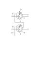
また、上記実施形態において、校正用電路20は、電流センサ2aのフェライトコア15の内側を一回だけ通過するように配置した場合を例示したが、例えば、図6に示すように、校正用電路20をフェライトコア15に巻き付けることで、フェライトコア15の内側を複数回通過するように配置してもよい。
この場合、校正用電流として大きな電流を流すことなく電流センサ2aにより計測される校正用電流の電流値を大きくすることができる。この結果、誤差の検出がより容易となり、より精度よく校正することができる。
この場合、校正用電流として大きな電流を流すことなく電流センサ2aにより計測される校正用電流の電流値を大きくすることができる。この結果、誤差の検出がより容易となり、より精度よく校正することができる。
また、上記実施形態では、ストリングSが発電を停止しているときに電流センサ2aの校正を行うように構成した場合を例示したが、ストリングSが発電を行っているときであっても、電流センサ2aの校正を行うことはできる。
例えば、ストリングSの発電電力が安定している場合には、校正用電流が供給されていないときに計測される第1電流値情報と、校正用電路20に校正用電流を供給しているときに計測される第2電流値情報との差分には、ストリングSの発電電流による影響が小さくなる。よって、ストリングSの発電電力が安定している場合には、ストリングSが発電を行っているときであっても、電流センサ2aの校正を行うように構成してもよい。
例えば、ストリングSの発電電力が安定している場合には、校正用電流が供給されていないときに計測される第1電流値情報と、校正用電路20に校正用電流を供給しているときに計測される第2電流値情報との差分には、ストリングSの発電電流による影響が小さくなる。よって、ストリングSの発電電力が安定している場合には、ストリングSが発電を行っているときであっても、電流センサ2aの校正を行うように構成してもよい。
この場合、ストリングSの発電電流による影響が小さいので、電流センサ2aの校正を行うことができる。
さらに、この場合、校正用電流を供給しているときの第2電流値情報の計測時の直前、又は直後において校正用電流が供給されていないときの第1電流値情報を計測することが好ましい。これにより、校正用電流を供給しているときと、校正用電流を供給していないときとの間で、ストリングSの発電電力の状態に変化がないようにすることができ、より精度よく校正を行うことができる。
さらに、この場合、校正用電流を供給しているときの第2電流値情報の計測時の直前、又は直後において校正用電流が供給されていないときの第1電流値情報を計測することが好ましい。これにより、校正用電流を供給しているときと、校正用電流を供給していないときとの間で、ストリングSの発電電力の状態に変化がないようにすることができ、より精度よく校正を行うことができる。
なお、今回開示された実施の形態はすべての点で例示であって制限的なものではないと考えられるべきである。本発明の範囲は、上記した意味ではなく、特許請求の範囲によって示され、特許請求の範囲と均等の意味、及び範囲内でのすべての変更が含まれることが意図される。
1 太陽光発電パネル
2a 電流センサ
2v 電圧センサ
3 PLC子機
4 接続箱
5 集電箱
7 電力変換装置
9 PLC親機
10 監視装置
11 変圧器
15 フェライトコア
16 ホール素子
20 校正用電路
31 データ生成部
32 校正処理部
33 異常検知部
34 電流供給部
92 校正処理部
93 異常検知部
P1 集電系統
PC1 パワーコンディショナ
L、L1・・Ln 出力電路
S、S1・・Sn ストリング
2a 電流センサ
2v 電圧センサ
3 PLC子機
4 接続箱
5 集電箱
7 電力変換装置
9 PLC親機
10 監視装置
11 変圧器
15 フェライトコア
16 ホール素子
20 校正用電路
31 データ生成部
32 校正処理部
33 異常検知部
34 電流供給部
92 校正処理部
93 異常検知部
P1 集電系統
PC1 パワーコンディショナ
L、L1・・Ln 出力電路
S、S1・・Sn ストリング
Claims (7)
- 太陽光発電パネルの発電電流を計測する電流センサを校正する校正システムであって、
前記電流センサは、前記太陽光発電パネルの発電電力を出力するための出力電路の電流値を計測するように構成され、
前記出力電路とともに前記電流センサによって電流値が計測されるように配置される校正用電路と、
前記校正用電路に所定電流値の校正用電流を供給する供給部と、
前記校正用電路に前記校正用電流が供給されていないときに前記電流センサによって計測された第1電流値と、前記校正用電路に前記校正用電流が供給されたときに前記電流センサによって計測された第2電流値との差分に基づいて前記電流センサを校正する校正処理部と、
を備えている校正システム。 - 前記太陽光パネル及び前記電流センサは複数であり、
前記校正用電路は、一の電路によって複数の前記電流センサによる電流値の計測がなされるように配置されている請求項1に記載の校正システム。 - 前記校正処理部は、前記太陽光発電パネルが発電していないときに計測された前記第1電流値と、前記太陽光発電パネルが発電していないときに計測された前記第2電流値との差分に基づいて前記電流センサを校正する請求項1または請求項2に記載の校正システム。
- 前記校正処理部による校正結果に基づいて、前記電流センサの異常を検知する異常検知部をさらに備えている請求項1から請求項3のいずれか一項に記載の校正システム。
- 前記電流センサは、前記出力電路が内側に配置され当該出力電路に電流が流れることで磁束を生じさせる環状部材と、生じた磁束を検出し流れる電流の電流値を表す信号を出力する検出部とを備え、
前記校正用電路は、前記出力電路とともに前記環状部材の内側に配置されている請求項1から請求項4のいずれか一項に記載の校正システム。 - 太陽光発電パネルの状態を監視する太陽光発電用監視システムであって、
前記太陽光発電パネルの発電電流を計測する電流センサと、
請求項1に記載の校正システムと、
を備えている太陽光発電用監視システム。 - 太陽光発電パネルの発電電流を計測する電流センサであって前記太陽光発電パネルを出力するための出力電路の電流値を計測するように構成されている電流センサを校正する校正方法であって、
前記出力電路とともに前記電流センサによって電流値が計測されるように配置される校正用電路に所定電流値の校正用電流を供給する供給ステップと、
前記校正用電路に前記校正用電流が供給されていないときに前記電流センサによって計測された第1電流値と、前記校正用電路に前記校正用電流が供給されたときに前記電流センサによって計測された第2電流値との差分に基づいて前記電流センサを校正する校正処理ステップと、
を備えている校正方法。
Priority Applications (1)
| Application Number | Priority Date | Filing Date | Title |
|---|---|---|---|
| CN201580018162.0A CN106164682A (zh) | 2014-05-30 | 2015-05-29 | 校正系统、太阳能发电用监视系统及校正方法 |
Applications Claiming Priority (2)
| Application Number | Priority Date | Filing Date | Title |
|---|---|---|---|
| JP2014-112881 | 2014-05-30 | ||
| JP2014112881A JP2015227788A (ja) | 2014-05-30 | 2014-05-30 | 校正システム、太陽光発電用監視システム、及び校正方法 |
Publications (1)
| Publication Number | Publication Date |
|---|---|
| WO2015182741A1 true WO2015182741A1 (ja) | 2015-12-03 |
Family
ID=54699061
Family Applications (1)
| Application Number | Title | Priority Date | Filing Date |
|---|---|---|---|
| PCT/JP2015/065540 Ceased WO2015182741A1 (ja) | 2014-05-30 | 2015-05-29 | 校正システム、太陽光発電用監視システム、及び校正方法 |
Country Status (3)
| Country | Link |
|---|---|
| JP (1) | JP2015227788A (ja) |
| CN (1) | CN106164682A (ja) |
| WO (1) | WO2015182741A1 (ja) |
Cited By (4)
| Publication number | Priority date | Publication date | Assignee | Title |
|---|---|---|---|---|
| US20150168529A1 (en) * | 2013-12-13 | 2015-06-18 | National Instruments Corporation | Self-Calibration of Source-Measure Unit via Capacitor |
| WO2017141580A1 (ja) * | 2016-02-17 | 2017-08-24 | 住友電気工業株式会社 | 監視装置、収集装置、監視システムおよび監視方法 |
| JP2017147923A (ja) * | 2016-02-17 | 2017-08-24 | 住友電気工業株式会社 | 監視装置、収集装置、監視システムおよび監視方法 |
| CN108418549A (zh) * | 2018-03-07 | 2018-08-17 | 阳光电源股份有限公司 | 光伏组件iv曲线同步扫描方法、装置以及光伏发电系统 |
Families Citing this family (5)
| Publication number | Priority date | Publication date | Assignee | Title |
|---|---|---|---|---|
| JP2018007332A (ja) * | 2016-06-28 | 2018-01-11 | 京セラ株式会社 | 電力変換装置及びその校正方法 |
| JP6819154B2 (ja) * | 2016-09-05 | 2021-01-27 | 三菱電機株式会社 | パワーコンディショナ |
| CN107040206B (zh) * | 2017-05-02 | 2018-09-07 | 东北电力大学 | 一种光伏电池板积灰状态监测系统与清洗周期优化方法 |
| DE102018217532A1 (de) * | 2018-10-12 | 2020-04-16 | Continental Automotive Gmbh | Sensor und Verfahren zur Überprüfung eines Sensors |
| JP7244403B2 (ja) * | 2019-11-20 | 2023-03-22 | Necプラットフォームズ株式会社 | 校正方法及び導出システム |
Citations (4)
| Publication number | Priority date | Publication date | Assignee | Title |
|---|---|---|---|---|
| JP2004245653A (ja) * | 2003-02-12 | 2004-09-02 | Nippon Soken Inc | 電流測定装置および電流測定方法 |
| JP2005354773A (ja) * | 2004-06-09 | 2005-12-22 | Nissan Motor Co Ltd | モータ駆動制御装置 |
| JP2012205078A (ja) * | 2011-03-25 | 2012-10-22 | Sumitomo Electric Ind Ltd | 太陽光発電用監視システム |
| JP2014006203A (ja) * | 2012-06-26 | 2014-01-16 | Kyocera Corp | 電流計測システムおよび電流計測方法 |
Family Cites Families (3)
| Publication number | Priority date | Publication date | Assignee | Title |
|---|---|---|---|---|
| CN201449412U (zh) * | 2009-08-24 | 2010-05-05 | 江阴爱康太阳能器材有限公司 | 太阳能发电监测报警装置 |
| CN201490727U (zh) * | 2009-09-04 | 2010-05-26 | 中海阳(北京)新能源电力股份有限公司 | 一种太阳能发电系统 |
| WO2011070899A1 (ja) * | 2009-12-07 | 2011-06-16 | 株式会社 東芝 | 太陽光発電システム |
-
2014
- 2014-05-30 JP JP2014112881A patent/JP2015227788A/ja active Pending
-
2015
- 2015-05-29 WO PCT/JP2015/065540 patent/WO2015182741A1/ja not_active Ceased
- 2015-05-29 CN CN201580018162.0A patent/CN106164682A/zh active Pending
Patent Citations (4)
| Publication number | Priority date | Publication date | Assignee | Title |
|---|---|---|---|---|
| JP2004245653A (ja) * | 2003-02-12 | 2004-09-02 | Nippon Soken Inc | 電流測定装置および電流測定方法 |
| JP2005354773A (ja) * | 2004-06-09 | 2005-12-22 | Nissan Motor Co Ltd | モータ駆動制御装置 |
| JP2012205078A (ja) * | 2011-03-25 | 2012-10-22 | Sumitomo Electric Ind Ltd | 太陽光発電用監視システム |
| JP2014006203A (ja) * | 2012-06-26 | 2014-01-16 | Kyocera Corp | 電流計測システムおよび電流計測方法 |
Cited By (7)
| Publication number | Priority date | Publication date | Assignee | Title |
|---|---|---|---|---|
| US20150168529A1 (en) * | 2013-12-13 | 2015-06-18 | National Instruments Corporation | Self-Calibration of Source-Measure Unit via Capacitor |
| US10175334B2 (en) * | 2013-12-13 | 2019-01-08 | National Instruments Corporation | Self-calibration of source-measure unit via capacitor |
| WO2017141580A1 (ja) * | 2016-02-17 | 2017-08-24 | 住友電気工業株式会社 | 監視装置、収集装置、監視システムおよび監視方法 |
| JP2017147923A (ja) * | 2016-02-17 | 2017-08-24 | 住友電気工業株式会社 | 監視装置、収集装置、監視システムおよび監視方法 |
| CN108352808A (zh) * | 2016-02-17 | 2018-07-31 | 住友电气工业株式会社 | 监视装置、收集装置、监视系统及监视方法 |
| CN108352808B (zh) * | 2016-02-17 | 2020-01-14 | 住友电气工业株式会社 | 监视装置、收集装置、监视系统及监视方法 |
| CN108418549A (zh) * | 2018-03-07 | 2018-08-17 | 阳光电源股份有限公司 | 光伏组件iv曲线同步扫描方法、装置以及光伏发电系统 |
Also Published As
| Publication number | Publication date |
|---|---|
| JP2015227788A (ja) | 2015-12-17 |
| CN106164682A (zh) | 2016-11-23 |
Similar Documents
| Publication | Publication Date | Title |
|---|---|---|
| JP2015227788A (ja) | 校正システム、太陽光発電用監視システム、及び校正方法 | |
| US8655469B2 (en) | Advanced process control optimization | |
| JP4888994B2 (ja) | 電流モニタ装置 | |
| JP5393715B2 (ja) | 診断装置、太陽光発電システム及び診断方法 | |
| CN102447299B (zh) | 用于向装置提供冗余功率的系统和方法 | |
| JP2015198485A (ja) | 異常検出装置、異常検出システム、及び異常検出方法 | |
| EP4142084A1 (en) | Parallel generator systems and controllers therefor | |
| CN106256085B (zh) | 异常检测装置 | |
| KR20170066107A (ko) | 홀 센서 및 dsp 연산 구조 기반 서브 미터링 분배전반 | |
| JP6319929B1 (ja) | 直流地絡検出装置、太陽光発電システム、及びプログラム | |
| JP2015226423A (ja) | 異常判定装置、異常判定方法、及びコンピュータプログラム | |
| KR101319449B1 (ko) | 무선 라우팅 역할을 수행하는 무정전 전력 측정장치 | |
| TWI609187B (zh) | Insulation monitoring device | |
| US20150234016A1 (en) | Method and arrangement for locating short-circuits in energy supply systems | |
| CA3073435C (en) | Detection of loop resistance and leakage current in input/output (i/o) loop | |
| KR20170118393A (ko) | Mppt를 활용한 태양광 발전 모니터링 시스템 | |
| KR101318983B1 (ko) | 전력량계의 이상 여부를 알리는 무정전 전력품질 측정장치 | |
| JP2015226288A (ja) | 通信システム、太陽光発電用監視システム、通信方法、及びコンピュータプログラム | |
| JP2016103110A (ja) | 多重化制御装置 | |
| JP6396768B2 (ja) | 電流測定装置、電流測定システム、電流測定方法、及び電流測定プログラム | |
| AU2016202536A1 (en) | Method and system for determining the structure of an electricity transmission grid and associated computer program | |
| KR20170009352A (ko) | 오차보정시스템 | |
| JP2015152353A (ja) | 故障検知装置および、それを備える太陽光発電システム | |
| JP6012130B2 (ja) | クラスタ状態監視装置 | |
| JP5925533B2 (ja) | 保護継電装置 |
Legal Events
| Date | Code | Title | Description |
|---|---|---|---|
| 121 | Ep: the epo has been informed by wipo that ep was designated in this application |
Ref document number: 15799676 Country of ref document: EP Kind code of ref document: A1 |
|
| NENP | Non-entry into the national phase |
Ref country code: DE |
|
| 122 | Ep: pct application non-entry in european phase |
Ref document number: 15799676 Country of ref document: EP Kind code of ref document: A1 |