WO2015182635A1 - 地盤改良工法 - Google Patents
地盤改良工法 Download PDFInfo
- Publication number
- WO2015182635A1 WO2015182635A1 PCT/JP2015/065174 JP2015065174W WO2015182635A1 WO 2015182635 A1 WO2015182635 A1 WO 2015182635A1 JP 2015065174 W JP2015065174 W JP 2015065174W WO 2015182635 A1 WO2015182635 A1 WO 2015182635A1
- Authority
- WO
- WIPO (PCT)
- Prior art keywords
- injection device
- ground
- slurry
- soil
- layer
- Prior art date
Links
Images


Classifications
-
- E—FIXED CONSTRUCTIONS
- E02—HYDRAULIC ENGINEERING; FOUNDATIONS; SOIL SHIFTING
- E02D—FOUNDATIONS; EXCAVATIONS; EMBANKMENTS; UNDERGROUND OR UNDERWATER STRUCTURES
- E02D3/00—Improving or preserving soil or rock, e.g. preserving permafrost soil
- E02D3/12—Consolidating by placing solidifying or pore-filling substances in the soil
-
- E—FIXED CONSTRUCTIONS
- E02—HYDRAULIC ENGINEERING; FOUNDATIONS; SOIL SHIFTING
- E02D—FOUNDATIONS; EXCAVATIONS; EMBANKMENTS; UNDERGROUND OR UNDERWATER STRUCTURES
- E02D2250/00—Production methods
- E02D2250/003—Injection of material
-
- E—FIXED CONSTRUCTIONS
- E02—HYDRAULIC ENGINEERING; FOUNDATIONS; SOIL SHIFTING
- E02D—FOUNDATIONS; EXCAVATIONS; EMBANKMENTS; UNDERGROUND OR UNDERWATER STRUCTURES
- E02D2300/00—Materials
- E02D2300/0004—Synthetics
- E02D2300/0018—Cement used as binder
-
- E—FIXED CONSTRUCTIONS
- E02—HYDRAULIC ENGINEERING; FOUNDATIONS; SOIL SHIFTING
- E02D—FOUNDATIONS; EXCAVATIONS; EMBANKMENTS; UNDERGROUND OR UNDERWATER STRUCTURES
- E02D2300/00—Materials
- E02D2300/0004—Synthetics
- E02D2300/0018—Cement used as binder
- E02D2300/0023—Slurry
Definitions
- the present invention relates to a ground improvement technique for cutting a soil (in-situ soil) in the ground to be improved, mixing and stirring water and a solidifying material (for example, cement), and creating a ground consolidated body.
- a soil in-situ soil
- a solidifying material for example, cement
- a drilling hole is drilled in the ground to be improved, an injection device is inserted into the drilling hole, and a high-pressure fluid (for example, water) is sprayed radially outward from the injection device while cutting the soil, and the injection device Rotate and move vertically (pick up or push down), and mix and agitate the in-situ soil and the solidified material by jetting or discharging a solidified material such as cement, for example.
- a technique for creating a ground solid consolidated body having a rotating body shape is widely known (see, for example, Patent Document 1).
- the ratio W / C between the supplied solidifying material (cement) and water is low, and so-called “rich blending” is desirable.
- the present invention has been proposed in view of the above-mentioned problems of the prior art, and is formed into a so-called “rich blend” by reducing the ratio W / C of the solidified material (cement) and water.
- the strength or quality of the consolidated body can be improved, the solidified material can be reliably conveyed from the supply source to the injection device, and the amount of the solidified material processed as industrial waste can be reduced.
- the purpose is to provide a ground improvement method.
- the ground improvement method of the present invention includes a step of drilling a digging hole (H) in the ground (G) to be improved, an injection device (1) inserted into the digging hole (H), and a ground ( G) a step of rotating (injecting) the injection device (1) in a vertical direction while injecting a fluid (stable liquid, partition forming material) for cutting, and a step of injecting a solidified material from the injection device (1).
- a step of rotating (injecting) the injection device (1) in the vertical direction while injecting the fluid (stable liquid, partition formation material) for cutting the ground (G) from the injection device (1) is performed by the partition formation material.
- a step of cutting the ground (G) and a step of spraying the solidified material (C) while cutting the ground (G) by spraying the stabilizing liquid after spraying the partition forming material It is characterized by.
- the step of collecting the mixture of the stable liquid discharged to the ground side and the cut soil (S: slurry) by the slurry collecting mechanism (2) A step of transporting the slurry (S) recovered by the slurry recovery mechanism (2) to the slurry processing mechanism (4) and adding an enzyme (E: cellulolytic enzyme such as cellulase) from the enzyme supply source (5); Is preferred.
- an enzyme E: cellulolytic enzyme such as cellulase
- the ground improvement method of the present invention is also a contaminated water purification method, a step of drilling a drilling hole (H) in the ground (G) to be improved, and an injection device (1) inserted into the drilling hole (H) for injection.
- the step of moving in the vertical direction while injecting is characterized in that zeolite is injected from the injection device (1).
- the solidified material having a high blending ratio of water to cement (W / C) of 26% to 40% since the solidified material having a high blending ratio of water to cement (W / C) of 26% to 40% is used, the strength of the formed ground consolidated body is increased. (Quality) can be improved as compared with the strength of the underground consolidated body formed by a conventional poorly-solidified solidifying material.
- the solidifying material solidified material with a high W / C content of 26% to 40%
- a separation layer (L D ) composed of a partition forming material is formed prior to the step of cutting the soil with the stabilizing liquid.
- a separation layer (L D : a layer composed of a partition forming material) suppresses the contact of the rich blended solid material injected into the ground with the mixture of the stabilizing liquid and the cut soil. Therefore, only the mixture of the stabilizing liquid and the cut soil is discharged as slurry (S) to the ground side, and the solidified material with rich blend is hardly discharged to the ground side.
- the layer of the partition-forming material the (L D separating layer)
- the (L D separating layer) it is possible to suppress the solidification agent injected into the ground from being discharged to the ground side. Since the solidified material is suppressed from being discharged to the ground side as the slurry (S), according to the present invention, the amount of the solidified material discharged to the ground side as the slurry (S) as compared with the prior art. The construction cost is saved by that amount.
- this invention has the process of collect
- the slurry (S) spouted to the ground side Can be recovered. Therefore, it is possible to prevent the slurry (S) from being scattered around the construction site and deteriorating the working environment.
- E cellulolytic enzyme such as cellulase
- the guar gum naturally water-soluble polymer material in the stabilizing solution is decomposed by the cellulose-degrading enzyme (E), and water and soil Only mixed solution.
- E cellulose-degrading enzyme
- the spraying device (1) is rotated or rotated to move (pull up) while spraying the fluid (stable liquid, partition forming material) for cutting the ground (G) from the spraying device (1).
- a zeolite layer L Z : zeolite bottom plate
- It said zeolite deck slabs the (L Z), for example in the ground near such reactor building (21), by arranging the outflow (leakage) pathway or diffusion paths of groundwater contaminated with radioactive materials (W G), atomic Groundwater (W G ) contaminated by radioactive material flowing out and diffusing from the reactor building (21) etc.
- the ground improvement method of the present invention also acts as a purification method for groundwater contaminated with radioactive substances.
- FIG. 3 is a process diagram showing a process that follows the process shown in FIG. 2.
- FIG. 4 is a cross-sectional view taken along line AA of the injection device shown in FIG. 3.
- FIG. 4 is a process diagram showing a process that follows the process shown in FIG. 3.
- FIG. 6 is a process diagram showing a process that follows the process shown in FIG. 5.
- 7 is a flowchart showing the procedure of FIGS. It is a figure explaining the problem which should be solved by other embodiment of this invention. It is explanatory drawing which shows other embodiment of this invention. It is process drawing which shows the process of other embodiment of this invention.
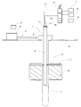
- FIG. 1 the ground on which the construction method of the present invention is applied is indicated by the symbol G.
- the rod-shaped injection device 1 is inserted into the excavation hole H drilled in the ground G.
- the erection mechanism 6 indicated by a dotted line in FIG. 1 is a device for inserting (building) the injection device 1 into the excavation hole H.
- the injection device 1 has a double tube structure (see FIG. 4).
- the inner space of the inner tube 15 constitutes a flow path through which a rich blended solidifying material is supplied.
- An annular space between the inner tube 15 and the outer tube 16 constitutes a flow path to which a stabilizing liquid or a partition forming material is supplied.
- a solidifying material discharge port 11 (jet port) is provided at the lower end of the spray device 1.
- a plurality (two in FIG. 1) of injection ports 12 are provided at a position vertically above the lower end of the injection device 1.
- the plurality of injection ports 12 are arranged so as to be symmetric with respect to a vertical central axis (not shown).
- the plurality of injection ports 12 are provided for injecting the stabilizing liquid or the partition forming material.
- the stabilizing liquid and the partition forming material are not simultaneously ejected from the plurality of ejection ports 12.
- a partition forming material is injected from the injection port 12 prior to the step of cutting the soil by injection of the stabilizing liquid from the plurality of injection ports 12.
- a layer L W of a mixture of which is cut a stable liquid soil, between the layer L C of the solidifying material (consolidated material wealth formulation), and soil which has been cut with the partition forming material separation layer L D composed of a mixture is formed.
- a solution containing 5% by weight of a thickening agent for example, guar gum, which is a natural water-soluble polymer material
- a thickening agent for example, guar gum, which is a natural water-soluble polymer material
- the partition forming material is a solution containing 5% by weight of a thickener (eg, guar gum which is a natural water-soluble polymer material) and 5% by weight of sodium silicate (water glass). Then, by mixing with the local soil by a partition-forming material is injected into the soil to form a separation tank L D.
- the solidifying material is a mixture of rich cement and water, for example, a mixture having a W / C of 26% to 40%.
- W / C 26% is a theoretical value, and W / C cannot be made lower than this.
- W / C exceeded 40%, the desired strength (quality) could not be obtained in the underground consolidated body.
- a superplasticizer is added to the solidifying material (W / C is 26% to 40%).
- W / C is 26% to 40%.
- % Solidified material can be transported by a pump for transporting a poorly blended solidified material (ordinary solidifying material transport pump).
- a polycarboxylic acid compound for example, “Tupol”, a product name of Takemoto Yushi Co., Ltd.
- a superplasticizer in an amount of 3 to 7% by weight based on the cement.
- the case where the polycarboxylic acid compound was added by 5% by weight with respect to the cement was suitable for transporting the solidified solidified material.
- a mixture (mixed solidified material) obtained by mixing and stirring 100 parts by weight of cement, 25 parts by weight of water, and 5 parts by weight of a polycarboxylic acid compound is a normal solidified material transport pump, that is, a poorly mixed material.
- the solidified material (W / C was 100% or more) could be transported by a pump used for transporting the solidified material.
- the injection device 1 communicates with a partition forming material supply source 7 via an introduction part 14 and a supply line 17, and communicates with a stable liquid supply source 8 via an introduction part 14 and a supply line 18. Yes. Furthermore, the injection device 1 communicates with the solidification material supply source 9 via the introduction part 13 and the supply line 19.
- the supply lines 17, 18 and 19 are provided with a switching valve 10. By switching the switching valve 10, each of the partition forming material, the stabilizing liquid, and the solidifying material is supplied to the injection device 1 or stopped.
- the switching valve 10 blocks the supply of the partition forming material from the partition forming material supply source 7 to the injection device 1, but supplies the stabilizing liquid from the stable liquid supply source 8 to the injection device 1, and solidifies the material.
- the switching position is to supply the solidified material from the supply source 9 to the injection device 1.
- the pump of the partition forming material supply source 7 (not shown), the pump of the stabilizing liquid supply source 8 (not shown), and the pump of the solidifying material supply source 9 (not shown) are turned on. With the OFF control, it is possible to control the supply / stop of supply of the partition forming material, the stabilizing liquid, and the solidifying material.
- the conventional ground improvement In the construction method the solidified material flows back to the ground side and is discharged as a slurry that is a mixture of water, soil, and solidified material.
- the layer L D (separation layer) of the mixture of the partition forming material and the cut soil is a layer of the mixture of the stable liquid and the cut soil.
- L W are partitioned from the layer L C of solidifying material wealth formulation. Therefore, a layer L of a stabilizing solution that cutting soil layer L C of solidifying material wealth formulation, rarely resulting in mixed beyond the separation layer L D.
- Solidifying material wealth formulation is injected, as the vertical dimension of the solidifying material layer L C increases (becomes thicker) layers L D (separation layer) of the partition-forming material is moved upwardly.
- the mixture of which is cutting the stabilizer soil is discharged to the ground side (as a slurry), it is consolidated material in the solidifying material layer L C is discharged to the ground side beyond the separation layer L D Suppressed or prevented.
- the solidified material (rich blended solidified material) discharged (injected) into the soil is discharged to the ground side by the partition forming material layer L D (separated layer). Is suppressed. Therefore, in the illustrated embodiment, the slurry discharged (reversely flowing) to the ground side includes the stabilizing liquid and the cut soil, but the solidified material is prevented from being discharged to the ground side as a slurry. It is.
- the thickness dimension of the layer L D (separation layer) of the partition forming material is such that the solidifying material discharge port 11 (discharge port at the lower end of the injection device 1) and the injection port from which the stable liquid or the partition forming material is discharged. 12 is equal to a vertical distance L with respect to 12 (a plurality of injection ports provided above the discharge port 11). Then, the vertical distance L between the discharge port 11 and the injection port 12, the separation layer L D constituted by the partition-forming material is solidified layer L W and wealth formulation of a mixture of which is cut a stable liquid soil partition and a layer L C of wood, is set to solidification material thickness required to prevent the mixing with the mixture of soil that has been cut with the stabilizing solution wealth formulation (vertical dimension). In the illustrated embodiment, the thickness dimension (vertical distance) L is set to 1 m.
- a slurry recovery mechanism 2 is provided on the ground surface portion of the excavation hole H.
- the slurry is ejected to the ground side through an annular space between the inner wall surface of the excavation hole H and the injection device 1.
- the slurry discharged to the ground side is recovered by the slurry recovery mechanism 2. Therefore, the situation where the slurry is scattered around the construction site and the working environment is deteriorated is prevented.
- a known technique may be applied to the slurry collecting mechanism 2.
- the slurry recovered by the slurry recovery mechanism 2 is sent to the slurry processing mechanism 4 via the slurry conveyance line 3.
- An enzyme (cellulolytic enzyme such as cellulase) is added from the enzyme supply source 5 to the slurry sent to the slurry processing mechanism 4.
- the slurry sent to the slurry processing mechanism 4 is a mixed solution of the stabilizing liquid and the cut soil, and inclusion of the solidified material is suppressed. Therefore, in FIG.
- FIG. 2 shows a state where the excavation hole H is drilled in the ground G to be improved.
- the injection device 1 is inserted into the excavation hole H. 2
- the inner diameter D H of the borehole H is larger than the outer diameter of the injector 1 to be inserted.
- the inner diameter D H of the borehole H is set to a value which the slurry is smoothly discharged to the ground side.
- the depth L H borehole H is set according to the depth of the soil to be ground improvement.
- FIG. 3 showing a step subsequent to the step shown in FIG. 2, the rod-shaped injection device 1 is inserted into the excavation hole H.
- a known built-in mechanism 6 is used.
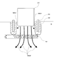
- FIG. 4 which is a cross-sectional view taken along the line AA in the vicinity of the injection port 12 of the injection device 1 in FIG. 3, shows only the injection device 1 and does not show the cross section of the excavation hole H.
- the injection device 1 has a double tube structure with the inner tube 15 and the outer tube 16, and the solidified material flows through the inner tube 15, and the inner tube 15 and the outer tube 16.
- Stabilizing liquid or partition forming material flows through the space between them. Note that the stabilizing liquid and the partition forming material are not sprayed at the same time.
- the stabilizing liquid and the partition forming material introducing portion 14 are connected to the plurality of injection ports 12 through an annular space (see FIG. 4) between the inner tube 15 and the outer tube 16 of the injection device 1 and a pipe (not shown). Communicate.
- FIG. 3 shows a state in which the injection device 1 is inserted into the excavation hole H.
- the injection device 1 In the state of FIG. 3, none of the solidifying material, the stabilizing liquid, and the partition forming material is injected or discharged into the soil.
- the injection device 1 is rotated around the central axis in the longitudinal direction and pulled up. Is provided.
- the slurry recovery mechanism 2 provided on the ground surface portion of the excavation hole H communicates with the annular space between the inner wall surface of the excavation hole H and the outer peripheral surface of the injection device 1, and the slurry ejected to the ground side Is recovered.
- the slurry recovery mechanism 2 is operated by a power mechanism (not shown).
- FIG. 5 is a process diagram for cutting the ground G by injecting a partition forming material in a process subsequent to the process shown in FIG. 3. 5 and 6, the illustration of the erection mechanism 6 is omitted.
- the partition forming material is introduced into the injection device 1 from the introduction portion 14 through the supply line 17 and the switching valve 10 from the partition forming material supply source 7, and an annular shape between the inner tube 15 and the outer tube 16.
- the jets J are jetted radially outward from the plurality of jets 12 as jets J.
- the injection device 1 rotates the injection device 1 to move in the vertical direction (pulls up) while injecting the jet J of the partition forming material to cut the ground G.
- a layer L D of a mixture of soil, which is cut a partition forming material is formed.
- a separation layer L D constituted by the partition-forming material by injecting the partition-forming material prior to the step of cutting the soil by injecting stabilizing solution, by forming a separation layer L D constituted by the partition-forming material by injecting the partition-forming material, stabilized a layer L W of a mixture of soil is cut with a liquid, without a layer L C of the solidified material with each other intermingle, to maintain the separated state.
- the switching valve 10 opens only the supply line 17 from the partition forming material supply source 7 to the injection device 1, and the stable liquid supply source. 8 and the supply lines 18, 19 from the solidification source 9 to the injection device 1 are closed. Therefore, only the partition forming material is supplied to the injection device 1, and the stabilizing liquid and the solidified material are not supplied to the injection device 1.
- slurry that is a mixture of the partition forming material and the cut soil is generated and flows back to the ground side. Slurry flowing back to the ground side is recovered by the slurry recovery mechanism 2.
- the thickness dimension of the layer L D (separation layer) of the partition forming material divides the predetermined dimension L (the layer L W of the mixture of the stabilizing liquid and the cut soil and the layer L C of the enriched solidified material, If the injection device 1 is pulled up to the thickness dimension necessary to prevent the solidified material of rich composition from mixing with the mixture of the stabilizer and the cut soil: 1 m in the illustrated embodiment) 5 is completed, and the process shown in FIG. Proceed to the step shown in. In the process shown in FIG. 6, the solidified material is sprayed while spraying the stabilizing liquid and cutting the ground G. In the process shown in FIG.
- the switching valve 10 shuts off the supply line L17 from the partition forming material supply source 7 to the injection device 1, but the supply line L18 from the stable liquid supply source 8 to the injection device 1 and the solidified material.
- the supply line L19 from the supply source 9 to the injection device 1 is opened.
- the stabilizing liquid supplied from the stabilizing liquid supply source 8 via the supply line 18 and the switching valve 10 passes through the annular space between the inner pipe 15 and the outer pipe 16 from the upper introduction portion 14 of the injection device 1. Through (see FIG. 4), it is injected radially outward from the plurality of injection ports 12 into the ground.
- the solidified material is introduced from the solidified material supply source 9 through the supply line 19 and the switching valve 10 from the solidified material introducing portion 13 at the top of the injection device 1 into the injection device 1, and the internal space of the inner pipe 15 (FIG. 4). And is discharged from the discharge port 11 into the ground.
- the stabilizing liquid is injected as a jet J from the injection device 1 and cuts the ground G. And the injection device 1 is pulled up in the vertical direction while rotating. On the other hand, the solidified material is discharged (injected) from the discharge port 11 provided at the lower end of the injection device 1. Then, the in-situ soil and the solidifying material are mixed to form an underground consolidated body.
- a mixture of the stable liquid and the cut soil is obtained by injecting the stable liquid from the injection device 1 into the ground, cutting and stirring the ground G, and pulling up in the vertical direction while rotating about the axis of the injection device 1.
- Layer LW is formed.
- the layers of solidifying material L C ground solid body
- Solidifying material is discharged (injected) to continue from the injection device 1, the vertical dimension of the layer L C of the solidified material is increased (thickened when), brought to it, the layer of the partition-forming material (isolation layer L D) is upwardly Moving. Therefore, the region above the isolation layer L D composed of a partition-forming material, i.e. only from the layer L W of a mixture of which is cut a stable liquid soil, slurry (a mixture of which is cut a stable liquid soil) is It is discharged to the ground side. Solidifying material wealth blended in the layer L C of solidifying material can hardly be discharged to the ground side.
- the slurry recovered by the slurry recovery mechanism 2 becomes a mixture of soil and water when enzymatically decomposed by the slurry processing mechanism 4. And if it is a mixture of soil and water, it is not necessary to treat it as industrial waste in a specialized treatment facility.
- the process shown in FIG. 6 is continued until the solidified material layer L C (underground consolidated body) reaches the vicinity of the ground and the vertical dimension of the underground consolidated body reaches a predetermined value.
- FIG. 7 is a flowchart showing the procedure of the steps shown in FIGS. The operation procedure of the illustrated embodiment will be described with reference to FIGS. 2 to 6 while mainly referring to the flowchart of FIG.
- step S ⁇ b> the switching valve 10 is switched to open only the supply line 17 from the partition forming material supply source 7 to the injection device 1, and the supply line 18 from the stable liquid supply source 8 and the solidification material supply source 9.
- the supply line 19 is closed and the partition forming material is supplied to the injection device 1.
- the process proceeds to step S2.
- step S2 the thickness is required thickness of the separation layer L D constituted by the partition-forming material: determines whether the reached (vertical dimension L predetermined dimension). In other words, in step S2, it is determined whether or not the lifting amount of the injection device 1 is greater than or equal to the predetermined dimension L. If raising the amount of the injector 1 (thickness of the separation layer L D) is smaller than the thickness L required separation layer L D returns to (Step S2 "NO") Step S1, the ground G by injecting partition forming material cutting the to continue the process of forming the separation layer L D. On the other hand, raising the amount of the injector 1 as long (separation layer thickness L D) separation layer L D required thickness L more (step S2 is "YES"), the process proceeds to step S3.
- step S 3 the switching valve 10 is switched to close the supply line 17 from the partition forming material supply source 7 to the injection device 1, and the supply line 18 from the stabilizing liquid supply source 8 to the injection device 1 and the solidification material supply source 9.
- the supply line 19 to the injection device 1 is opened. Thereby, injection of a partition formation material stops, a stable liquid is injected in a horizontal direction, and a solidification material is discharged. And the injection device 1 is pulled up in the vertical direction while rotating while injecting the stabilizing liquid and cutting the ground G. At the same time, the solidified material is discharged (injected) from the discharge port 11 provided at the lower end of the injection device 1 and mixed with the cut in-situ soil to form an underground consolidated body.
- step S3 The slurry (mixed fluid of the stabilizing liquid and the cut soil) generated in step S3 is recovered by the recovery mechanism 2 on the ground side, and is transported to the slurry processing mechanism 4 by the slurry transport line 3. Enzyme is added from the enzyme supply source 5 to obtain a mixed solution of only water and soil. Therefore, it is not necessary to transport it to a treatment facility as industrial waste. Then, the process proceeds to step S4.
- step S4 the vertical dimension of the ground solid sintered layer L C solidifying material reaches near the ground becomes a desired size, determines whether Construction of underground caking body has been completed. If the solidified material layer L C (underground consolidated body) does not reach the desired thickness and the formation of the underground consolidated body is not completed (step S4 is “NO”), step S3 is performed. The process of discharging (injecting) the solidified material while injecting the stabilizing liquid and cutting the ground G is continued. Layer L C of the solidified material becomes a desired vertical dimension, as long as the reclamation of ground consolidation body is completed (step S4 is "YES"), the process proceeds to step S5.
- step S5 the switching valve 10 is switched to close the supply line 18 from the stabilizing liquid supply source 8 to the injection device 1 and the supply line 19 from the solidifying material supply source 9 to the injection device 1, thereby stabilizing the liquid and the solidifying material.
- To the injection device 1 is stopped.
- movement pulled up to the ground side at a predetermined speed are also stopped. Since the passage from the partition forming material supply source 7 to the injection device 1 is closed in step S3, the partition formation material is not supplied to the injection device 1 also in step S5. And the slurry collection
- the strength ( Quality) can be improved as compared with the case of a conventional solidified material with poor blending (W / C is 100% or more).
- the solidifying material (C: solidified material with a high W / C content of 26% to 40%) contains a high fluidizing agent, an increase in the viscosity of the solidifying material (C) is suppressed. It can be transported using a normal solidifying material transport pump (pump for transporting poorly blended solidifying material in the prior art).
- step S1 for forming an isolation layer L D for injecting a partition-forming material composed of a partition forming material
- separating layer L a layer L W of a mixture of soil is cut with a stabilizing solution by D, and a layer L C of solidifying material wealth formulations are separated. Therefore, the consolidated material of wealth compounding are prevented from contacting the fluid mixture with was cut with Antei liquid soil (mixed liquid constituting the layer L W), and the soil on the ground that has been cut and Antei solution only fluid mixing (mixing liquid constituting the layer L W) is discharged as a slurry. For this reason, since the rich blended solidified material is hardly discharged to the ground side, the consumption of the solidified material can be reduced as compared with the prior art.
- the slurry collection mechanism 2 is a mixture of the stable liquid discharged to the ground side and the cut soil
- the slurry around the construction site may be contaminated by the slurry ejected to the ground side. Absent.
- the slurry recovered by the slurry recovery mechanism 2 (mixture of the stabilizing liquid and the cut soil) is conveyed to the slurry processing mechanism 4, and the cellulolytic enzyme is added from the enzyme supply source 5, so that the slurry becomes water and It becomes a mixture of soil only and is no longer an industrial waste. Therefore, it is not necessary to transport to the processing facility, and the slurry processing cost can be saved.
- FIG. 8 in preparation for a case where groundwater WG1 contaminated with radioactive material flows out from the reactor building 21 (including radioactive material and groundwater storage facilities: the same applies hereinafter) into the ground G.
- a continuous wall 22 (for example, a frozen soil wall) is formed so as to surround 21.
- the continuous wall 22 blocks the flow of the groundwater WG1 containing radioactive material that flows out and diffuses from the reactor building 21 into the ground, and the contaminated groundwater WG1 flows out and diffuses beyond the frozen soil wall 22 to the outside. This is to prevent this.
- symbol 23 in FIG. 8 is an apparatus for forming a frozen earth wall.
- a zeolite layer (L Z : zeolite bottom plate) extending in the horizontal direction in the ground G and below the reactor building 21 by the method according to the embodiment of FIGS. Form.
- the thickness B of the zeolite deck slabs L Z is sufficiently adsorbed while groundwater WG2 contaminated with radioactive material is passed through the zeolite deck slabs L Z (transmission), cesium encompassed the groundwater WG2 is Zeolite zeolite bottom plate L Z
- the thickness is set as much as possible. The thickness is case-by-case depending on the degree of contamination and various conditions.
- the horizontal range of the zeolite deck slabs L Z is runoff of groundwater WG2 contaminated with radioactive material exiting (leaking) from the reactor building 21, is set in a range in which the diffusion path is fully covered.
- zeolites because they have chemical properties of adsorbing cesium is the main component of the radioactive material, flows out from the reactor building 21 in the ground of the direction just below ( leakage), groundwater WG2 to diffusion when passing through the zeolite deck slab L Z, cesium adsorption, are removed.
- cesium occupies most of the radioactive material, if cesium can be removed, the concentration of the radioactive material in the groundwater WG2 is reduced to a value that does not cause a problem, that is, a reference value or less.
- the groundwater WG1 flowing over the zeolite deck slabs L Z is blocked by a continuous wall 22, it does not diffuse. In order to prevent the spread of contamination groundwater WG2, the continuous wall 22 and zeolite deck slabs L Z are connected.
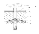
- Figure 10 is a similar procedure to the embodiment illustrated in Figures 1-7, show a process of forming a zeolite base plate L Z extending in a horizontal direction.
- the digging hole H is drilled in the ground G
- the injection device 1 is inserted into the digging hole H
- the jetting device 1 while jetting a fluid (partition forming material) that cuts the ground G from the jetting device 1.
- the step of rotating (moving up) in the vertical direction is the same as in FIGS. 1 to 7.
- the injection device 1 rotates while being jetted with the jet J of the partition forming material and cutting the ground G, and is pulled upward in the vertical direction.
- a layer L D separation layer of the mixture with the cut soil is formed.
- zeolite is discharged into the ground from the discharge port 11 provided at the lower end of the injection device 1 instead of the solidified material in the embodiment of FIGS.
- the separation layer L D is interposed, discharged zeolite stabilizer and injected from the discharge port 12 was, without mixing the cutting soil by jet of stabilizer, zeolite bottom plate extending in the horizontal direction LZ is formed.
- the layer L D of a mixture of a layer L W of a mixture of which is cut a stable liquid soil, and soil is cut a partition forming material (separation layer) is formed.
- the zeolite layer Lz zeolite bottom plate
- the layer L W Between the layers L W and zeolite layers Lz mixtures to have been cut with the stabilizing liquid soil (zeolite deck slab), so the separation layer L D constituted by the partition-forming material is interposed, the layer L W The stable liquid and the cut soil are prevented from mixing into the zeolite layer Lz (zeolite bottom plate), and the separated state is maintained.
- the process shown in FIG. 10 is continued until the zeolite layer Lz (zeolite bottom plate) has a predetermined thickness at a predetermined vertical position (depth) in the ground.
- Cross-sectional shape of the zeolite layer Lz (zeolite deck slabs) i.e., horizontal extent of the zeolite deck slabs L Z
- the shape of the zeolite deck slabs L Z noncircular e.g. semi-circular, fan-shaped
Landscapes
- Engineering & Computer Science (AREA)
- Life Sciences & Earth Sciences (AREA)
- Structural Engineering (AREA)
- Agronomy & Crop Science (AREA)
- Environmental & Geological Engineering (AREA)
- Soil Sciences (AREA)
- General Life Sciences & Earth Sciences (AREA)
- Mining & Mineral Resources (AREA)
- Paleontology (AREA)
- Civil Engineering (AREA)
- General Engineering & Computer Science (AREA)
- Consolidation Of Soil By Introduction Of Solidifying Substances Into Soil (AREA)
Abstract
Description
造成された地中固結体の強度(品質)を向上するためには、供給される固化材(セメント)と水との比率W/Cが低く、いわゆる「富配合」であることが望ましい。
また、噴射装置から噴射された固化材の全てが地中で固化するのではなく、大量の固化材がスラリーとして地上側に排出される。そのため、産業廃棄物として廃棄処理されてしまう固化材が大量に存在するのが実情である。そして、W/Cが低く、いわゆる「富配合」である場合には、廃棄処理されてしまう固化材の量が多くなり、その分だけ施工コストが高騰してしまう。
上述した様な理由から、従来技術では、W/Cが100%以上の、いわゆる「貧配合」の固化材を使用せざるを得なかった。
前記噴射装置(1)から地盤(G)を切削する流体(安定液、仕切形成材)を噴射しつつ噴射装置(1)を回転して垂直方向に移動する(引き上げる)工程は、仕切形成材を噴射して地盤(G)を切削する工程と、仕切形成材を噴射した後に安定液を噴射して地盤(G)を切削しつつ固化材(C)を噴射する工程を有していることを特徴としている。
リー)をスラリー回収機構(2)により回収する工程と、
スラリー回収機構(2)で回収されたスラリー(S)をスラリー処理機構(4)に搬送し、酵素供給源(5)から酵素(E:セルラーゼ等のセルロース分解酵素)を添加する工程を有することが好ましい。
ここで、固化材(W/Cが26%~40%の富配合の固化材)には高流動化剤を包含しており、富配合にしても固化材の粘性の増加は抑制されている。そのため本発明によれば、従来技術で用いられている固化材搬送用のポンプ、すなわち貧配合の固化材搬送用のポンプによって、富配合の固化材を搬送することが可能である。
係る分離層(LD:仕切形成材で構成された層)により、地中に噴射された富配合の固化材は、安定液と切削された土壌との混合物に接触することが抑制される。
そのため、地上側には安定液と切削された土壌との混合物のみがスラリー(S)として排出され、富配合の固化材は地上側には殆ど排出されない。すなわち、仕切形成材の層(LD:分離層)により、地中に噴射された固化材が地上側に排出されてしまうことが抑制される。
固化材がスラリー(S)として地上側に排出されてしまうことが抑制されるため、本発明によれば、従来技術に比較して、スラリー(S)として地上側へ排出される固化材の量を抑制され、その分だけ施工コストが節約される。
また、スラリー回収機構(2)で回収されたスラリー(S)をスラリー処理機構(4)に搬送し、酵素供給源(5)から酵素(E:セルラーゼ等のセルロース分解酵素)を添加する工程を有することにより、安定液と切削された土との混合溶液であるスラリー(S)は、セルロース分解酵素(E)により安定液中のグアガム(天然水溶性高分子材料)が分解され、水と土のみの混合液となる。ここで、水と土のみの混合液であれば産業廃棄物として処理する必要がないので、従来技術とは異なり、スラリーを産業廃棄物として処理施設に陸送する必要がなくなる。
前記ゼオライト底版(LZ)を、例えば原子炉建屋(21)等の周辺の地中で、放射性物質により汚染された地下水(WG)の流出(漏洩)経路或いは拡散経路に配置すれば、原子炉建屋(21)等から地中に流出、拡散する放射性物質による汚染された地下水(WG)は、地中に流出、拡散する過程で前記ゼオライト底版(LZ)に流入し、前記ゼオライト底版(LZ)を通過(或いは透過)する。
地下水(WG)がゼオライト底版(LZ)を通過(透過)する過程で、放射性物質の大部分を占めるセシウムは、そのほとんどがゼオライトにより吸着され地下水から除去される。その結果、前記ゼオライト底版(LZ)を通過(透過)した地下水における放射性物質濃度は大きく低下し、所謂「基準値」以下のレベルとなる。すなわち、本発明の地盤改良工法は、放射性物質で汚染された地下水の浄化方法としても作用する。
最初に実施形態に係る地盤改良工法を施工するのに必要な機器について、図1を参照して説明する。
図1において、本発明の工法が施工される地盤は、符号Gで示されている。地盤Gに穿孔された掘削孔Hには、ロッド状の噴射装置1が挿入されている。
ここで、図1において点線で示す建込機構6は、掘削孔H内に噴射装置1を挿入する(建て込む)ための機器である。
図1において、噴射装置1の下端部には、固化材の吐出口11(噴射口)が設けられている。噴射装置1の下端部より垂直方向上方の位置には、複数(図1では2個)の噴射口12(例えばノズル)が設けられている。
噴射装置1の水平断面において、複数の噴射口12(図1では2個)は、垂直方向中心軸(図示せず)に対して対称となる様に配置されている。そして複数の噴射口12は、安定液或いは仕切形成材を噴射するために設けられている。
図1で示すように、安定液と切削された土壌との混合物の層LWと、固化材(富配合の固化材)の層LCとの間に、仕切形成材と切削された土壌との混合物で構成された分離層LDが形成される。
図1では、仕切形成材を噴射して分離層LDを形成する工程の後、仕切形成材で構成され
た分離層LDが形成されており、噴射口12からは安定液の噴流Jが噴射されて、土壌を切削している状態が示されている。ここで噴射装置1下端の吐出口11から固化材が吐出(噴射)されており、固化材の層LCを形成している。
仕切形成材は、図示の実施形態では、増粘剤(例えば、天然水溶性高分子材料であるグアガム)5重量%と、ケイ酸ナトリウムソーダ(水ガラス)5重量%を包含する溶液である。そして仕切形成材を土壌中に噴射して現地土と混合することにより、分離槽LDを構成する。
固化材は、図示の実施形態では、富配合のセメントと水の混合物であり、例えば、W/Cが26%~40%の混合物である。なお、W/C=26%は理論値であり、これよりもW/Cを低くすることはできない。一方、発明者の実験では、W/Cが40%を超えると、地中固結体に所望の強度(品質)をうることが出来なかった。
図示の実施形態では、高流動化剤として、ポリカルボン酸系化合物(例えば、竹本油脂社の製品名「チューポール」)を、セメントに対して3~7重量%添加している。発明者の実験では、ポリカルボン酸系化合物をセメントに対して5重量%添加した場合が、地中固結体の固化材の搬送に際して好適であった。
発明者の実験では、セメント100重量部、水25重量部、ポリカルボン酸系化合物5重量部を混合、攪拌した混合物(富配合の固化材)は、通常の固化材搬送用ポンプ、すなわち貧配合(W/Cが100%以上)の固化材を搬送するために用いられるポンプにより搬送することが出来た。
供給ライン17、18、19は、切換弁10を介装している。切換弁10を切り換えることにより、仕切形成材、安定液、固化材の各々が、噴射装置1に供給され或いは供給停止される。
なお切換弁10に代えて、仕切形成材供給源7のポンプ(図示を省略)、安定液供給源8のポンプ(図示を省略)、固化材供給源9のポンプ(図示を省略)のON-OFF制御により、仕切形成材、安定液、固化材の供給/供給停止を制御することが出来る。
上側に逆流し、排出されてしまう。
これに対し、図示の実施形態では、図1で示す様に、仕切形成材と切削された土壌との混合物の層LD(分離層)により、安定液と切削された土壌との混合物の層LWと、富配合の固化材の層LCとは仕切られている。そのため、土壌を切削している安定液の層Lは、富配合の固化材の層LCは、分離層LDを越えて混合してしまうことはほとんどない。
その結果、安定液と切削された土壌との混合物は(スラリーとして)地上側に排出されるが、固化材層LCにおける固化材が分離層LDを越えて地上側に排出されることが抑制或いは防止される。
換言すれば、図示の実施形態では、仕切形成材の層LD(分離層)により、土壌中に吐出(注入)された固化材(富配合の固化材)が地上側に排出されてしまうことが抑制される。そのため、図示の実施形態では、地上側に排出される(逆流する)スラリーには安定液と切削された土壌が包含されているが、固化材がスラリーとして地上側に排出されることが抑制されるのである。
そして、前記吐出口11と噴射口12との垂直方向距離Lは、仕切形成材により構成される分離層LDが、安定液と切削された土壌との混合物の層LWと富配合の固化材の層LCとを仕切り、富配合の固化材が安定液と切削された土壌との混合物と混合するのを抑制するのに必要な厚さ(垂直方向寸法)に設定される。
図示の実施形態では、当該厚さ寸法(垂直方向距離)Lは、1mに設定されている。
図1において、スラリーは、掘削孔Hの内壁面と噴射装置1の間の断面円環状の空間を介して地上側に噴出する。
図1において、スラリー回収機構2により、地上側に排出されるスラリーを回収している。そのため、スラリーが施工現場周辺に飛散して、作業環境を劣化させてしまう事態が防止される。
スラリー回収機構2については、公知技術を適用すれば良い。
ここで従来技術では、地上側に排出されるスラリーは固化材を包含しているため、産業廃棄物として処理する必要がある。しかし、図1においては、上述した通り、スラリー処理機構4に送られたスラリーは安定液と切削された土壌との混合溶液であり、固化材を包含することは抑制される。そのため、図1において、スラリー処理機構4に送られたスラリーにセルロース分解酵素を添加すると、安定液中のグアガム(天然水溶性高分子材料)がセルロース分解酵素により分解されるので、水と土の混合液となる。水と土のみの混合液であれば、産業廃棄物には該当せず、産業廃棄物として処理施設に輸送する必要がなくなる。
図2には、改良すべき地盤Gに掘削孔Hを穿孔した状態が示されている。掘削孔Hには、噴射装置1が挿入される。
図2において、掘削孔Hの内径DHは、挿入する噴射装置1の外径よりも大きい。ここで
、安定液で地盤Gの土壌を切削する際に、掘削孔Hの内壁面と噴射装置1の外周面との間の断面円環状の空間を通ってスラリーが地上側に排出される(逆流する)が、掘削孔Hの内径DHはスラリーが円滑に地上側に排出される値に設定されている。
掘削孔Hの深さLHは、地盤改良すべき土壌の深さに応じ設定される。
図3における噴射装置1の噴射口12付近のA-A線矢視断面図である図4は、噴射装置1のみを示しており、掘削孔Hの断面は示していない。図4で示すように、噴射装置1は、内管15及び外管16との二重管構造となっており、内管15の内部を固化材が流過し、内管15と外管16との間の空間を安定液或いは仕切形成材が流過する。
なお、安定液と仕切形成材は同時に噴射されることはない。工程により何れか一方のみが噴射される。安定液及び仕切形成材の導入部14は、噴射装置1の内管15と外管16との間の円環状の空間(図4参照)及び図示しない配管を介して、複数の噴射口12に連通している。
明示はされていないが、安定液及び仕切形成材の噴射と同時に、噴射装置1を長手方向中心軸回りに回転させて引き上げるため、図示しない機構(回転機構と昇降機構)が、建込機構6に設けられている。
図3において、掘削孔Hの地表部分に設けられたスラリー回収機構2は、掘削孔Hの内壁面と噴射装置1外周面の間の円環状空間と連通しており、地上側に噴出するスラリーを回収している。なおスラリー回収機構2は、図示しない動力機構により稼動している。
図5において仕切形成材は、仕切形成材供給源7から供給ライン17、切換弁10を介して、導入部14から噴射装置1に導入され、内管15と外管16との間の円環状の空間(図4参照)を通って、複数の噴射口12より地中に、噴流Jとして半径方向外方に噴射される。
そして噴射装置1は、仕切形成材の噴流Jを噴射して地盤Gを切削しつつ、噴射装置1を回転して垂直方向に移動する(引き上げる)。その結果、仕切形成材と切削された土壌との混合物の層LDと(分離層)が形成される。図1を参照して説明したように、安定液を噴射して土壌を切削する工程に先立ち、仕切形成材を噴射して仕切形成材で構成された分離層LDを形成することにより、安定液と切削された土壌との混合物の層LWと、固化材の層LCとが交じり合うこと無く、分離された状態を維持する。
ここで、仕切形成材を噴射して地盤Gを切削する工程においても、仕切形成材と切削された土壌の混合物であるスラリーが発生し、地上側に逆流する。地上側に逆流したスラリーはスラリー回収機構2で回収される。
で示す工程に進む。
図6で示す工程では、安定液を噴射して地盤Gを切削しつつ、固化材を噴射する。そして図6で示す工程では、切換弁10は、仕切形成材供給源7から噴射装置1への供給ラインL17を遮断するが、安定液供給源8から噴射装置1への供給ラインL18及び固化材供給源9から噴射装置1への供給ラインL19を開放する。
これにより、安定液供給源8から供給ライン18、切換弁10を介して供給される安定液は、噴射装置1上部導入部14から、内管15と外管16との間の円環状の空間(図4参照)を通って、複数の噴射口12より地中に、半径方向外方に噴射されている。そして、固化材供給源9から供給ライン19、切換弁10を介して、噴射装置1上部の固化材導入部13から固化材が噴射装置1に導入され、内管15(図4)の内部空間を通って、吐出口11より地中に吐出される。
一方、固化材は、噴射装置1の下端に設けられた吐出口11から吐出(噴射)される。そして、原位置土と固化材が混合されて、地中固結体が造成される。
上述した様に、安定液と切削された土壌との混合物の層LWと固化材の層LCとの間には、仕切形成材で構成された分離層LDが介在しているので、安定液と切削された土壌との混合物の層LWと固化材の層LCとが混じり合うことが抑制される。
図6で示す工程は、固化材の層LC(地中固結体)が地上付近まで達して地中固結体の垂直方向寸法が所定の数値となるまで継続される。
図7のフローチャートを主として参照しつつ、図2~図6をも参照して、図示の実施形態の作業手順を説明する。
図7において、ステップS1では、切換弁10を切り換えて、仕切形成材供給源7から噴射装置1への供給ライン17のみ開放し、安定液供給源8からの供給ライン18及び固化材供給源9から供給ライン19は閉鎖して、仕切形成材を噴射装置1に供給する。そして仕切形成材を噴射口12から地中に噴射しつつ、噴射装置1を回転して垂直方向に引き上げ、以って、仕切形成材で構成された分離層LDを形成する。そしてステップS2に進む。
法L:所定寸法)に到達したか否かを判定する。換言すれば、ステップS2では、噴射装置1の引き上げ量が所定寸法L以上であるか否かを判定している。
噴射装置1の引き上げ量(分離層LDの厚さ)が分離層LDの必要な厚さLよりも小さければ(ステップS2「NO」)ステップS1に戻り、仕切形成材を噴射し地盤Gを切削し、分離層LDを形成する工程を継続する。
一方、噴射装置1の引き上げ量(分離層LDの厚さ)が分離層LDの必要な厚さL以上であれば(ステップS2が「YES」)、ステップS3に進む。
そして噴射装置1は、安定液を噴射して地盤Gを切削しつつ、回転しながら垂直方向に引き上げられる。同時に、噴射装置1の下端に設けられた吐出口11から固化材が吐出(噴射)され、切削された原位置土と混合して、地中固結体が造成される。
そしてステップS4に進む。
固化材の層LC(地中固結体)が所望の厚さに達しておらず、地中固結体の造成が完了していない場合には(ステップS4が「NO」)、ステップS3に戻り、安定液を噴射して地盤Gを切削しつつ固化材を吐出(噴射)する工程を継続する。
固化材の層LCが所望の垂直方向寸法となり、地中固結体の造成が完了したのであれば(ステップS4が「YES」)、ステップS5に進む。
そして、噴射装置1を回転させる作動と、所定速度で地上側へ引き上げる作動も停止する。
仕切形成材供給源7から噴射装置1への通路はステップS3で閉鎖しているので、ステップS5においても仕切形成材は噴射装置1に供給されない。
そして、スラリー回収機構2、スラリー搬送ライン3及びスラリー処理機構4も停止し、ステップS5に進み作業を終了する。
ここで、固化材(C:W/Cが26%~40%の富配合の固化材)には、高流動化剤を包含しているため、固化材(C)の粘性の増加が抑制され、通常の固化材搬送ポンプ(従来技術における貧配合の固化材を搬送するためのポンプ)を用いて搬送することが出来る。
離層LDによって安定液と切削された土壌との混合物の層LWと、富配合の固化材の層LCとが分離される。そのため、富配合の固化材が、安定液と切削された土壌との混合流体(層LWを構成する混合液体)に接触することが抑制され、地上側には安定液と切削された土壌との混合流体(層LWを構成する混合液体)のみがスラリーとして排出される。そのため、富配合の固化材は地上側には殆ど排出されないので、従来に比較し固化材の消費量を減少することができる。
そして、スラリー回収機構2で回収されたスラリー(安定液と切削された土壌との混合物)をスラリー処理機構4に搬送し、酵素供給源5からセルロース分解酵素を添加することにより、スラリーは水と土のみの混合液となり、産業廃棄物ではなくなる。そのため、処理施設に輸送する必要がなくなり、スラリー処理コストを節約することが出来る。
ここで図8に基づいて、上述した問題(射性物質で汚染された地下水の拡散)について説明する。
なお、図8における符号23は、凍土壁を形成するための装置である。
図8から明らかなように、連続壁22よりも地中深く流れる汚染地下水WG22の流れを遮ることが出来ないからである。
係る問題を解決するための実施形態を、図9及び図10に基づき説明する。
ゼオライト底版LZの厚さBは、放射性物質で汚染された地下水WG2がゼオライト底版LZを通過(透過)する間に、当該地下水WG2に包含されるセシウムがゼオライト底版LZのゼオライトにより充分吸着できる程度の厚さに設定される。なお、当該厚さは、汚染の程度や各種条件により、ケース・バイ・ケースである。
また、ゼオライト底版LZの水平方向の範囲は、原子炉建屋21から流出(漏洩)する放射性物質で汚染された地下水WG2の流出、拡散経路が十分にカバーされる範囲に設定される。
シウムを除去することが出来れば、地下水WG2における放射性物質濃度は、安全に問題がない数値、即ち基準値以下に低下する。
そして、ゼオライト底版LZの上方を流れる地下水WG1は連続壁22により遮られ、拡散することはない。
なお、汚染地下水WG2の拡散を防止するため、連続壁22とゼオライト底版LZは接続されている。
図10で示すように、地盤Gに掘削孔Hを穿孔し、掘削孔Hに噴射装置1を挿入し、噴射装置1から地盤Gを切削する流体(仕切形成材)を噴射しつつ噴射装置1を回転して垂直方向に移動する(引き上げる)工程については、図1~図7と同様である。
噴射装置1は、仕切形成材の噴流Jを噴射して地盤Gを切削しつつ、回転して垂直方向上方に引き上げられるが、図1~図7で示す実施形態と同様に、仕切形成材と切削された土壌との混合物の層LD(分離層)を形成する。
ここで分離層LDが介在するため、吐出されたゼオライトは吐出口12から噴射された安定液や、安定液の噴流により切削された土壌と混合すること無く、水平方向に延在するゼオライト底版LZを形成する。
安定液と切削された土壌との混合物の層LWとゼオライトの層Lz(ゼオライト底版)との間には、仕切形成材で構成された分離層LDが介在しているので、層LWの安定液と切削された土壌はゼオライトの層Lz(ゼオライト底版)に混入してしまうことが抑制され、分離された状態を維持する。
ゼオライトの層Lz(ゼオライト底版)の断面形状(すなわち、ゼオライト底版LZの水平方向の範囲)は、図1~図7に示す実施形態と同様に円形断面である。しかし、汚染水拡散の必要に応じて、ゼオライト底版LZの形状を非円形(例えば半円形、扇形)とすることもできる。
2・・・スラリー回収機構
3・・・スラリー搬送ライン
4・・・スラリー処理機構
5・・・酵素供給源
6・・・建込機構
7・・・仕切形成材供給源
8・・・安定液供給源
9・・・固化材供給源
10・・・切換弁
11・・・吐出口
12・・・噴射口
13・・・固化材導入部
14・・・安定液導入部、兼仕切形成材導入部
15・・・内管(噴射装置)
16・・・外管(噴射装置)
17・・・配管
G・・・地盤
H・・・掘削孔
LC・・・固化材の層
LD・・・仕切形成材の層(分離層)
LW・・・安定液と切削された土壌との混合物の層
21・・・原子炉建屋
22・・・連続壁
WG1、WG2・・・汚染地下水
LZ・・・ゼオライトの層(ゼオライト底版)
Claims (3)
- 改良するべき地盤に掘削孔を穿孔する工程と、掘削孔に噴射装置を挿入し、噴射装置から地盤を切削する流体を噴射しつつ噴射装置を回転して垂直方向に移動する工程と、噴射装置から固化材を噴射する工程を有し、
前記噴射装置から地盤を切削する流体を噴射しつつ噴射装置を回転して垂直方向に移動する工程は、仕切形成材を噴射して地盤を切削する工程と、仕切形成材を噴射した後に安定液を噴射して地盤を切削しつつ固化材を噴射する工程を有していることを特徴とする地盤改良工法。 - 地上側に排出された安定液と切削された土壌との混合物をスラリー回収機構により回収する工程と、
スラリー回収機構で回収されたスラリーをスラリー処理機構に搬送し、酵素供給源から分解酵素を添加する工程を有する請求項1の地盤改良工法。 - 改良するべき地盤に掘削孔を穿孔する工程と、掘削孔に噴射装置を挿入し、噴射装置から地盤を切削する流体を噴射しつつ噴射装置を回転して垂直方向に移動する工程と、前記噴射しつつ垂直方向に移動する工程では、噴射装置からゼオライトを噴射することを特徴とする地盤改良工法。
Priority Applications (5)
| Application Number | Priority Date | Filing Date | Title |
|---|---|---|---|
| US15/314,145 US20170204580A1 (en) | 2014-05-28 | 2015-05-27 | Method for improving ground |
| SG11201609037UA SG11201609037UA (en) | 2014-05-28 | 2015-05-27 | Ground improvement method |
| EP15799627.3A EP3165678B1 (en) | 2014-05-28 | 2015-05-27 | Ground improvement method |
| AU2015266559A AU2015266559B2 (en) | 2014-05-28 | 2015-05-27 | Ground improvement method |
| CA2950562A CA2950562C (en) | 2014-05-28 | 2015-05-27 | Method for improving ground |
Applications Claiming Priority (4)
| Application Number | Priority Date | Filing Date | Title |
|---|---|---|---|
| JP2014-109733 | 2014-05-28 | ||
| JP2014109733 | 2014-05-28 | ||
| JP2014166456A JP6415897B2 (ja) | 2014-05-28 | 2014-08-19 | 地盤改良工法 |
| JP2014-166456 | 2014-08-19 |
Publications (1)
| Publication Number | Publication Date |
|---|---|
| WO2015182635A1 true WO2015182635A1 (ja) | 2015-12-03 |
Family
ID=54698959
Family Applications (1)
| Application Number | Title | Priority Date | Filing Date |
|---|---|---|---|
| PCT/JP2015/065174 WO2015182635A1 (ja) | 2014-05-28 | 2015-05-27 | 地盤改良工法 |
Country Status (7)
| Country | Link |
|---|---|
| US (1) | US20170204580A1 (ja) |
| EP (1) | EP3165678B1 (ja) |
| JP (1) | JP6415897B2 (ja) |
| AU (1) | AU2015266559B2 (ja) |
| CA (1) | CA2950562C (ja) |
| SG (1) | SG11201609037UA (ja) |
| WO (1) | WO2015182635A1 (ja) |
Cited By (2)
| Publication number | Priority date | Publication date | Assignee | Title |
|---|---|---|---|---|
| CN111410465A (zh) * | 2020-04-26 | 2020-07-14 | 四川颐千石油工程有限公司 | 环保型水基岩屑固化剂及其应用 |
| WO2020244123A1 (zh) * | 2019-06-04 | 2020-12-10 | 东南大学 | 振杆密实法处理湿陷性黄土地基的方法 |
Families Citing this family (2)
| Publication number | Priority date | Publication date | Assignee | Title |
|---|---|---|---|---|
| WO2015156757A1 (en) * | 2014-04-07 | 2015-10-15 | Halliburton Energy Services, Inc. | Soil and rock grouting using a hydrajetting tool |
| CN108519477B (zh) * | 2018-04-24 | 2023-10-13 | 西南科技大学 | 一种季节性冻土地区路基模型试验系统 |
Citations (4)
| Publication number | Priority date | Publication date | Assignee | Title |
|---|---|---|---|---|
| JP2000290991A (ja) * | 1999-04-02 | 2000-10-17 | Nit Co Ltd | 地盤改良工法 |
| JP2001232344A (ja) * | 2000-02-23 | 2001-08-28 | Kurita Water Ind Ltd | 汚染土壌中に砂層を形成する方法及び汚染土壌の処理方法 |
| JP2004195387A (ja) * | 2002-12-19 | 2004-07-15 | Toko Corp | 土壌浄化工法及びそれに用いられる硬化材 |
| JP2006138192A (ja) * | 2004-11-11 | 2006-06-01 | Eikou Sangyo Kk | 噴射攪拌工法および噴射攪拌装置 |
Family Cites Families (5)
| Publication number | Priority date | Publication date | Assignee | Title |
|---|---|---|---|---|
| JPS56125530A (en) * | 1980-03-06 | 1981-10-01 | Kubota Ltd | Driving of pile |
| DE3737259C1 (en) * | 1987-11-03 | 1989-03-16 | Bauer Spezialtiefbau | Apparatus and method for high-pressure injection |
| JP2751074B2 (ja) * | 1989-10-04 | 1998-05-18 | 日東化学工業株式会社 | 地盤改良法およびそれに用いる装置 |
| DE10154201A1 (de) * | 2001-11-07 | 2003-05-22 | Frank Otto | Verfahren zur Bewehrung von Bauteilen aus dem Tiefbau durch Fasern, hierfür geeignete Vorrichtung und derart hergestellte Bauteile |
| ES2643216T3 (es) * | 2012-05-07 | 2017-11-21 | Novozymes A/S | Polipéptidos con actividad de degradación de xantano y polinucleótidos que codifican la misma |
-
2014
- 2014-08-19 JP JP2014166456A patent/JP6415897B2/ja active Active
-
2015
- 2015-05-27 US US15/314,145 patent/US20170204580A1/en not_active Abandoned
- 2015-05-27 AU AU2015266559A patent/AU2015266559B2/en active Active
- 2015-05-27 WO PCT/JP2015/065174 patent/WO2015182635A1/ja active Application Filing
- 2015-05-27 CA CA2950562A patent/CA2950562C/en active Active
- 2015-05-27 SG SG11201609037UA patent/SG11201609037UA/en unknown
- 2015-05-27 EP EP15799627.3A patent/EP3165678B1/en active Active
Patent Citations (4)
| Publication number | Priority date | Publication date | Assignee | Title |
|---|---|---|---|---|
| JP2000290991A (ja) * | 1999-04-02 | 2000-10-17 | Nit Co Ltd | 地盤改良工法 |
| JP2001232344A (ja) * | 2000-02-23 | 2001-08-28 | Kurita Water Ind Ltd | 汚染土壌中に砂層を形成する方法及び汚染土壌の処理方法 |
| JP2004195387A (ja) * | 2002-12-19 | 2004-07-15 | Toko Corp | 土壌浄化工法及びそれに用いられる硬化材 |
| JP2006138192A (ja) * | 2004-11-11 | 2006-06-01 | Eikou Sangyo Kk | 噴射攪拌工法および噴射攪拌装置 |
Non-Patent Citations (1)
| Title |
|---|
| See also references of EP3165678A4 * |
Cited By (3)
| Publication number | Priority date | Publication date | Assignee | Title |
|---|---|---|---|---|
| WO2020244123A1 (zh) * | 2019-06-04 | 2020-12-10 | 东南大学 | 振杆密实法处理湿陷性黄土地基的方法 |
| CN111410465A (zh) * | 2020-04-26 | 2020-07-14 | 四川颐千石油工程有限公司 | 环保型水基岩屑固化剂及其应用 |
| CN111410465B (zh) * | 2020-04-26 | 2020-11-24 | 四川颐千石油工程有限公司 | 环保型水基岩屑固化剂及其应用 |
Also Published As
| Publication number | Publication date |
|---|---|
| SG11201609037UA (en) | 2016-12-29 |
| US20170204580A1 (en) | 2017-07-20 |
| EP3165678A1 (en) | 2017-05-10 |
| CA2950562C (en) | 2019-12-31 |
| JP6415897B2 (ja) | 2018-10-31 |
| AU2015266559B2 (en) | 2019-05-02 |
| AU2015266559A1 (en) | 2016-12-15 |
| AU2015266559A8 (en) | 2017-01-05 |
| EP3165678A4 (en) | 2017-11-15 |
| JP2016006270A (ja) | 2016-01-14 |
| EP3165678B1 (en) | 2022-09-21 |
| CA2950562A1 (en) | 2015-12-03 |
Similar Documents
| Publication | Publication Date | Title |
|---|---|---|
| US10787865B2 (en) | In-situ injection of soil and groundwater—high pressure rotary jet grouting in-situ remediation system and method | |
| JP6415897B2 (ja) | 地盤改良工法 | |
| CN104174643B (zh) | 一种有机污染土壤和地下水原位修复装置及修复方法 | |
| CN205762952U (zh) | 一种土壤及地下水原位化学氧化高压旋喷注射修复系统 | |
| CN104624629B (zh) | 一种采用双向搅拌注入法修复有机物污染场地的方法 | |
| US6357968B1 (en) | Method and apparatus for constructing an underground barrier wall structure | |
| CN101245599B (zh) | 用高压喷射双液浆生成水平旋喷加固体的施工设备 | |
| CN205762951U (zh) | 土壤及地下水原位注入——高压旋喷注射原位修复系统 | |
| CN205676214U (zh) | 有机污染土壤和地下水原位修复注入井注入系统 | |
| US6834720B1 (en) | Method and apparatus for injecting particulate media into the ground | |
| KR100886220B1 (ko) | 경화제 제조장치와 슬라임 재처리장치를 이용한 고압분사지반개량 시스템 및 공법 | |
| KR20110041262A (ko) | 다중 고압분사 주입관 및 이를 이용한 오염토양의 지중 정화방법 | |
| KR100998969B1 (ko) | 원위치 토양의 오염정화방법 | |
| CN206868813U (zh) | 三管旋喷系统 | |
| US20040129319A1 (en) | Apparatus for in-situ remediation using a closed delivery system | |
| JP2007204941A (ja) | 炭酸化地盤改良工法 | |
| CN215785668U (zh) | 一种用于土壤修复的氧化药剂原位注入修复系统 | |
| JP3833943B2 (ja) | 薬液注入工法および薬液注入装置 | |
| JP3807545B2 (ja) | 汚染土壌の処理工法 | |
| KR100463104B1 (ko) | 시멘트밀크 중ㆍ고압분사를 통한 주상형 고결체 형성장치및 형성방법 | |
| JP4141184B2 (ja) | 汚染地下水の原位置浄化工法 | |
| JP4347717B2 (ja) | 土壌浄化方法 | |
| Shen et al. | Instant solidification of soft ground horizontally using jet-grouting | |
| JP2005349361A (ja) | 汚染土壌改良方法 | |
| CN85101005A (zh) | 高压旋转干喷法和双管旋转干喷器 |
Legal Events
| Date | Code | Title | Description |
|---|---|---|---|
| 121 | Ep: the epo has been informed by wipo that ep was designated in this application |
Ref document number: 15799627 Country of ref document: EP Kind code of ref document: A1 |
|
| ENP | Entry into the national phase |
Ref document number: 2950562 Country of ref document: CA |
|
| NENP | Non-entry into the national phase |
Ref country code: DE |
|
| REEP | Request for entry into the european phase |
Ref document number: 2015799627 Country of ref document: EP |
|
| WWE | Wipo information: entry into national phase |
Ref document number: 15314145 Country of ref document: US Ref document number: 2015799627 Country of ref document: EP |
|
| ENP | Entry into the national phase |
Ref document number: 2015266559 Country of ref document: AU Date of ref document: 20150527 Kind code of ref document: A |