WO2015182433A1 - ミキサ車、制御装置およびミキサドラムの回転制御方法 - Google Patents
ミキサ車、制御装置およびミキサドラムの回転制御方法 Download PDFInfo
- Publication number
- WO2015182433A1 WO2015182433A1 PCT/JP2015/064285 JP2015064285W WO2015182433A1 WO 2015182433 A1 WO2015182433 A1 WO 2015182433A1 JP 2015064285 W JP2015064285 W JP 2015064285W WO 2015182433 A1 WO2015182433 A1 WO 2015182433A1
- Authority
- WO
- WIPO (PCT)
- Prior art keywords
- mixer
- mixer drum
- power
- storage battery
- control
- Prior art date
- Legal status (The legal status is an assumption and is not a legal conclusion. Google has not performed a legal analysis and makes no representation as to the accuracy of the status listed.)
- Ceased
Links
Images


Classifications
-
- B—PERFORMING OPERATIONS; TRANSPORTING
- B60—VEHICLES IN GENERAL
- B60P—VEHICLES ADAPTED FOR LOAD TRANSPORTATION OR TO TRANSPORT, TO CARRY, OR TO COMPRISE SPECIAL LOADS OR OBJECTS
- B60P3/00—Vehicles adapted to transport, to carry or to comprise special loads or objects
- B60P3/16—Vehicles adapted to transport, to carry or to comprise special loads or objects for carrying mixed concrete, e.g. having rotatable drums
-
- B—PERFORMING OPERATIONS; TRANSPORTING
- B28—WORKING CEMENT, CLAY, OR STONE
- B28C—PREPARING CLAY; PRODUCING MIXTURES CONTAINING CLAY OR CEMENTITIOUS MATERIAL, e.g. PLASTER
- B28C5/00—Apparatus or methods for producing mixtures of cement with other substances, e.g. slurries, mortars, porous or fibrous compositions
- B28C5/42—Apparatus specially adapted for being mounted on vehicles with provision for mixing during transport
- B28C5/4203—Details; Accessories
- B28C5/4206—Control apparatus; Drive systems, e.g. coupled to the vehicle drive-system
- B28C5/421—Drives
Definitions
- the present invention relates to a mixer vehicle having an idling stop function for stopping an engine when the vehicle is stopped, a control device mounted on the mixer vehicle, and a rotation control method of the mixer drum.
- a vehicle idling stop function is known that stops the engine when the vehicle is stopped, such as waiting for a signal, for the purpose of reducing noise or improving fuel consumption.
- the idling stop function is mainly installed in ordinary vehicles such as passenger cars, but in recent years, an idling stop system for special vehicles such as construction vehicles has been developed.
- a mixer truck that transports ready-mixed concrete to the construction site must always rotate the mixer drum until the ready-mixed concrete is discharged, and the engine of the mixer truck is generally used as the drive source.
- the rotational power of the engine is transmitted to the hydraulic pump, the pressure oil discharged from the hydraulic pump is supplied to the hydraulic motor to drive it, and the mixer drum is driven to rotate by the rotation of the hydraulic motor.
- conventional mixer trucks are environmentally friendly, such as engine noise when the construction site is in the vicinity of a residential area, exhaust gas during tunnel construction, exhaust gas and noise during idling due to traffic lights and traffic jams, etc. Improvement was needed.
- Patent Document 1 discloses a power generation device driven by an engine, a power storage device that stores the output of the power generation device, an electric motor that is driven by electric power stored in the power storage device, and a second that is driven by the output of the electric motor. And a control device that detects the stop of the vehicle and enables the drum to rotate by driving the hydraulic motor by the electric motor and the second hydraulic pump when the engine is stopped by the operator's selection operation.
- a car is disclosed.
- the mixer vehicle described in Patent Document 1 has a problem that if the control device that detects the stop state of the vehicle fails, the mixer drum cannot be rotated in spite of the operation of the operator. Further, when a vehicle failure such as an engine trouble occurs, there is a limit to continuously stirring the ready-mixed concrete by rotating the mixer drum only with the electric power of the storage battery, so some measure is required.
- an object of the present invention is to provide a mixer vehicle, a control device, and a mixer drum rotation control method capable of appropriately processing the ready-mixed concrete in the mixer drum even when a vehicle failure occurs. is there.
- a mixer truck includes a vehicle body, a first drive circuit, and a second drive circuit.
- the vehicle body includes a generator that generates power by engine power, a first control unit that generates an idling stop signal and controls the engine, a mixer drum, and an operation unit that generates an operation signal by an operator's input operation.
- the first drive circuit includes a hydraulic motor that rotates the mixer drum, and a first hydraulic pump that is driven by the power of the engine and supplies liquid to the hydraulic motor.
- the second drive circuit includes a storage battery that stores the output of the generator, an electric motor that is driven by electric power stored in the storage battery, and a second motor that is driven by the electric motor and supplies liquid to the hydraulic motor.
- the second control unit executes a first control mode in which the mixer drum is rotated in a first direction by the electric power stored in the storage battery when the idling stop signal is received from the first control unit. .
- the second control unit executes a second control mode in which the mixer drum is rotated in a second direction opposite to the first direction with the electric power stored in the storage battery when the operation signal is received. To do.
- the mixer vehicle rotates the mixer drum by the first drive circuit when the engine is driven, such as during travel.
- the mixer vehicle rotates the mixer drum by the second drive circuit when idling is stopped such as when the vehicle is stopped. That is, in the second drive circuit, when the second control unit receives the idling stop signal from the first control unit, the mixer drum in a direction (first direction) in which the contents such as ready-mixed concrete are agitated in the mixer drum. It is comprised so that the 1st control mode which rotates may be performed.
- the second control unit when the second control unit receives the operation signal generated based on the input operation of the operation unit, the second control mode rotates the mixer drum in the second direction opposite to the first direction. Configured to perform.
- the second direction is typically a direction in which the contents are discharged from the mixer drum.
- the contents are transferred from the mixer drum to the outside by the electric power stored in the storage battery based on the input operation of the operation unit by the operator. It becomes possible to discharge. Thereby, the ready-mixed concrete in a mixer drum can be processed appropriately as an emergency treatment using the limited electric power of a storage battery.
- the discharge destination of the contents of the mixer drum is not particularly limited, and examples thereof include a mixer drum of another mixer vehicle.
- the second control unit drives the electric motor with a first output in the first control mode, and in the second control mode, the second control unit outputs a second electric motor that is larger than the first output. It may be configured to drive with the output of. Thereby, the content can be efficiently discharged from the mixer drum.
- the second drive circuit further includes a normally open switch element connected between the storage battery and the electric motor, and the second control unit is configured to switch the switch in the second control mode. It may be configured to close the element.
- a switch element a contactor, a relay, an electromagnetic switch or the like can be applied.
- a storage battery and an electric motor can be made into a direct connection state via a switch element in a 2nd control mode.
- the mixer drum can be rotated with a relatively large amount of electric power stored in the storage battery, so that the contents can be discharged efficiently.
- the mixer vehicle may further include a switching valve disposed between the second hydraulic pump and the hydraulic motor.
- the switching valve switches between a first state that forms a flow path for rotating the mixer drum in the first direction and a second state that forms a flow path for rotating the mixer drum in the second direction. Configured to be possible. Thereby, it becomes possible to appropriately switch the flow path according to the first control mode and the second control mode by the second control unit.
- the switching valve may be installed in the first drive circuit or may be installed in the second drive circuit.
- the vehicle body portion may further include a power storage device that stores the output of the generator.
- the power source for starting the second control unit may be the power stored in the power storage device or the power stored in the storage battery.
- the second control unit uses the power storage device as a power source in the first control mode.
- the second control mode it is determined whether or not the charge amount of the power storage device is equal to or less than a predetermined value, and when the charge amount is equal to or less than the predetermined value, the storage battery is used as a power source. Thereby, even when a vehicle failure occurs, a power source for the second control unit can be secured.
- a control device includes a generator that generates electric power using engine power, a control unit that generates an idling stop signal and controls the engine, a hydraulic motor that rotates a mixer drum, and the generator A storage battery that stores the output; an electric motor that is driven by the electric power stored in the storage battery; a hydraulic pump that is driven by the electric motor and supplies liquid to the hydraulic motor;
- the first receiving unit is configured to receive an idling stop signal from the control unit.
- the second receiving unit is configured to receive the operation signal.
- the controller executes a first control mode in which the mixer drum is rotated in a first direction by the electric power stored in the storage battery when the idling stop signal is received.
- the controller executes a second control mode in which the mixer drum is rotated in a second direction opposite to the first direction with the electric power stored in the storage battery when the operation signal is received.
- the mixer drum rotation control method when the mixer vehicle is idling stopped, the electric motor is driven with the first output by the electric power stored in the storage battery, so that the contents of the mixer drum are agitated. Rotating the mixer drum. At the time of input operation by an operator of the operation unit mounted on the mixer vehicle, the mixer drum rotates in the direction of discharging the contents by driving the electric motor with the second output with the electric power stored in the storage battery. Be made.
- the ready-mixed concrete in the mixer drum can be appropriately processed even when a vehicle failure occurs.
- 1 is a schematic side view showing a mixer truck according to an embodiment of the present invention. It is a schematic block diagram which shows the drive circuit of the mixer drum in the said mixer vehicle. It is a block diagram which shows the structure of the 2nd control part in the said mixer vehicle. It is a flowchart explaining the control method of the 2nd drive circuit by the said 2nd control part. It is a block diagram which shows schematic structure of the 2nd control part which concerns on the 2nd Embodiment of this invention. It is a flowchart explaining the operation example of the 2nd control mode by the said 2nd control part.
- FIG. 1 is a schematic side view showing a mixer truck according to an embodiment of the present invention
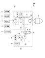
- FIG. 2 is a schematic configuration diagram showing a drive circuit of a mixer drum in the mixer truck.
- the mixer truck 100 includes a mixer drum 1 that transports mortar, ready-mixed concrete, or the like (hereinafter referred to as “raw concrete”) from a ready concrete factory to a construction site.
- the mixer drum 1 is rotatably installed on the gantry 2 of the mixer truck 100.
- the mixer truck 100 agitates the raw concrete with a plurality of spiral blades attached in the mixer drum 1 in order to prevent quality deterioration and condensation of the raw concrete.
- the mixer truck 100 discharges the raw concrete in the mixer drum 1 by rotating the mixer drum 1 in the reverse direction, and supplies it to the concrete placement site.
- the mixer vehicle 100 has a vehicle body portion 10.
- the vehicle body 10 includes a mixer drum 1, a gantry 2 (see FIG. 1), an engine 3, a generator 4, a first battery 5, a first control unit 6, a cabin 7 (see FIG. 1), an operation unit 8, and the like. .
- the engine 3 is a power source of the mixer vehicle 100 and is composed of an internal combustion engine such as a gasoline engine or a diesel engine.
- the generator 4 generates power with the rotational power of the engine and supplies the generated power to the first battery 5 and a second battery 21 described later.
- the generator 4 is not limited to one, and a plurality of generators may be provided.
- the first and second batteries 5 and 21 may be charged by a plurality of generators, or a generator may be assigned to each battery.
- the first battery 5 constitutes a “power storage device” that stores the output (electric power) of the generator 4, and is used as an electric power source of the electrical system in the vehicle body unit 10.
- the first battery 5 is, for example, a lead storage battery with a rating of 24 V in which 12 2 V unit cells are connected in series.
- the first control unit 6 is typically composed of a computer, and controls the electrical components of the mixer vehicle 100 in addition to the ignition control of the engine 3.
- the first control unit 6 executes an idling stop function for stopping the driving of the engine 3 under a predetermined condition when the mixer vehicle 100 stops due to a signal or the like.
- the predetermined condition is set as appropriate, and typically, the operation state of an accelerator pedal, a brake pedal, a side brake (parking brake), or the like is referred to.
- the first controller 6 is configured to transmit an idling stop signal S1 (see FIG. 3) to the second drive circuit 52 when executing the idling stop function.
- the first control unit 6 may be configured not to generate the idling stop signal S1 when it is determined that the engine cannot be normally driven due to an engine trouble or the like.
- the operation unit 8 is configured to generate an operation signal S2 (see FIG. 3) by an input operation of an operator (for example, a driver). As will be described later, the operation unit 8 is used to activate the second drive circuit 52 and drive the mixer drum 1 in an emergency in the event of a vehicle failure such as an engine trouble.
- the operation signal S ⁇ b> 2 is transmitted directly to the second drive circuit 52 without going through the first control unit 6. That is, the operation signal S ⁇ b> 2 is configured to be reliably transmitted to the second drive circuit 52 even when some trouble occurs in the first control unit 6.
- the operation unit 8 is typically composed of an appropriate switch mechanism such as a button switch, a toggle switch, or a lever switch.
- the operation signal S2 is not particularly limited as long as the input operation of the operation unit 8 can be electrically detected in the second drive circuit 52, and the signal potential is not limited.
- the signal potential may be a predetermined bias potential or a ground potential.
- the potential source may be the first battery 5, the second battery 21, or a dedicated battery.
- the operation unit 8 is typically installed inside the cabin 7 (driver's seat), but is not limited thereto, and may be installed outside the cabin 7 (for example, a predetermined position of the gantry 2).
- the mixer vehicle 100 includes a first drive circuit 51 that operates when the engine is driven and a second drive circuit 52 that operates when the engine is stopped as a drive circuit for the mixer drum 1.
- the first drive circuit 51 uses the engine 3 of the mixer truck 100 as its drive source.
- the first drive circuit 51 transmits the rotational power of the engine 3 to the first hydraulic pump 11 (first hydraulic pump) via PTO (Power Take Off), and is discharged from the first hydraulic pump 11.
- the pressure oil (liquid) is supplied to the hydraulic motor 12 (hydraulic motor) and driven, and the mixer drum 1 is driven to rotate by the rotation of the hydraulic motor 12.
- the second drive circuit 52 uses the electric motor 22 as its drive source.
- the second drive circuit 52 drives the electric motor 22 with the discharge output of the second battery 21, and transmits the rotational power of the electric motor 22 to the second hydraulic pump 23 (second hydraulic pump).
- the second hydraulic pump 23 supplies pressure oil to the hydraulic motor 12 to drive it, and the mixer drum 1 is driven to rotate by the rotation of the hydraulic motor 12.
- the first drive circuit 51 includes a first hydraulic pump 11, a hydraulic motor 12, and a first control valve 13.
- the first control valve 13 is disposed between the first hydraulic pump 11 and the hydraulic motor 12, and a hydraulic circuit 14 is configured between the hydraulic motor 12 and the first control valve 13.
- the first hydraulic pump 11 is driven by the power of the engine 3 and supplies pressure oil to the hydraulic motor 12.
- the hydraulic motor 12 rotates the mixer drum 1 upon receiving pressure oil supplied from the first hydraulic pump 11.
- the first control valve 13 switches the supply of pressure oil from the first hydraulic pump 11 to the hydraulic circuit 14 and the cutoff thereof, and the supply direction of the pressure oil in the hydraulic circuit 14.
- the first control valve 13 is configured by a three-position four-port electromagnetic switching valve having an A position, a B position, and a C position, and each position is a control signal transmitted from the first control unit 6. It is switched based on.
- the first control valve 13 is switched to position A when the mixer drum 1 is rotated in the forward direction (first direction), and C is rotated when the mixer drum is rotated in the reverse direction (second direction). Switch to position.
- the first control valve 13 is switched to the A position when stirring the raw control in the mixer drum 1, and is switched to the C position when discharging the raw control from the mixer drum 1.
- the first control valve 13 is switched to the B position when the supply of pressure oil from the first hydraulic pump 11 to the hydraulic motor 12 is shut off.
- the hydraulic circuit 14 may be provided with a relief valve that opens when a hydraulic pressure higher than a predetermined level is generated, a check valve that regulates the pressure oil supply direction, and the like at appropriate positions.
- a speed reducer may be installed between the hydraulic motor 12 and the mixer drum 1.
- the second drive circuit 52 includes the second battery 21, the electric motor 22, the second hydraulic pump 23, the second control valve 24, and the second control unit 25.
- the second drive circuit 52 may have a single unit structure.
- the second drive circuit 52 is installed at an appropriate position on the gantry 2, for example, between the cabin 7 and the hydraulic motor 12 as shown in FIG. 1.
- the second battery 21 constitutes a “storage battery” that stores the output (electric power) of the generator 4 and is used as a power source of the electric motor 22.
- the second battery 21 is not particularly limited as long as it is a chargeable / dischargeable secondary battery.
- a lithium ion battery having a rating of 25.9 V in which seven 3.7 V unit cells are connected in series is used. It is done.
- the electric motor 22 is driven by the electric power stored in the second battery 21, and is constituted by a direct current (DC) motor, for example. As will be described later, the electric motor 22 is charged in the second battery 21 when the second control unit 25 receives the idling stop signal S1 or when the operation signal S2 is received from the operation unit 8. Driven by power.
- DC direct current
- the second hydraulic pump 23 is driven by the electric motor 22.
- the second hydraulic pump 23 sucks the hydraulic oil stored in the tank 26 and supplies pressure oil to the hydraulic circuit 14.
- the amount of pressure oil discharged from the second hydraulic pump 23 is controlled by the output (rotation speed) of the electric motor 22.
- the second control valve 24 is configured as a “switching valve” disposed between the second hydraulic pump 23 and the hydraulic circuit 14.
- the second control valve 24 switches between supplying and shutting off the pressure oil from the second hydraulic pump 23 to the hydraulic circuit 14.
- the second control valve 24 is configured by a three-position four-port electromagnetic switching valve having a D position, an E position, and an F position, and each of the above positions is a second control in the present embodiment. Switching is performed based on a control signal transmitted from the unit 25.
- the second control valve 24 may be configured to be switched not only by a control signal from the second control unit 25 but also by an operator's manual operation.
- the second control valve 24 is switched to the D position when the engine 3 is driven, and shuts off between the second hydraulic pump 23 and the hydraulic circuit 14.
- the second control valve 24 is configured to be switched to the E position when the second control unit 25 receives an idling stop signal, as will be described later.
- the E position constitutes a “first state” that forms a flow path for rotating the mixer drum 1 in the forward direction, and pressure oil between the hydraulic circuit 14 and the tank 26 in the direction of rotating the hydraulic motor 12 in the forward direction. It is possible to circulate.
- the second control valve 24 is configured to be switched to the F position when the second control unit 25 receives an operation signal, as will be described later.
- the F position constitutes a “second state” in which a flow path for rotating the mixer drum 1 in the reverse direction is formed, and pressure oil is provided between the hydraulic circuit 14 and the tank 26 in the direction in which the hydraulic motor 12 is rotated in the reverse direction. It is possible to circulate.
- the second control unit 25 controls the driving of the second drive circuit 52.
- the second control unit 25 has a first control mode and a second control mode.
- the first control unit 25 rotates the mixer drum 1 in the forward direction (stirring direction) with the electric power stored in the second battery 21. It is configured to execute a control mode.
- the second control unit 25 receives the operation signal S2 from the operation unit 8, the second control mode rotates the mixer drum 1 in the reverse direction (discharge direction) with the electric power stored in the second battery 21. Execute.
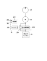
- FIG. 3 is a block diagram showing a configuration of the second control unit 25.
- the second control unit 25 includes a reception unit 251, a controller 252, an output adjustment unit 253, and a contactor 254.
- the second control unit 25 is configured as a control device that controls the operation of the second drive circuit 52.
- the second control unit 25 is driven using the first battery 5 as a power source.
- the receiving unit 251 is electrically connected to the first control unit 6 and the operation unit 8, and is configured to be able to receive the idling stop signal S1 and the operation signal S2.
- the receiving unit 251 is connected to the first control unit 6 by wire, but may be connected wirelessly.
- the receiving unit 251 functions as a first receiving unit that receives the idling stop signal S1 and a second receiving unit that receives the operation signal S2.
- the receiving unit 251 may be configured to be divided into these first and second receiving units.
- the controller 252 is typically configured by a computer and is electrically connected to the first battery 5, the receiving unit 251, the output adjusting unit 253, the contactor 254, and the second control valve 24.
- the controller 252 When the controller 252 receives the idling stop signal S1 via the receiving unit 251, the controller 252 executes the first control mode described above. Further, when the controller 252 receives the operation signal S2 via the receiving unit 251, the controller 252 executes the above-described second control mode.
- the operation unit 8 is used for emergency driving of the mixer drum 1 when a vehicle failure such as an engine trouble occurs. Therefore, typically, the receiving unit 251 receives either the idling stop signal S1 or the operation signal S2, but when both are received, the reception of the operation signal S2 is invalidated and the idling stop signal is given priority. May be configured to receive. Such a determination may be executed by the controller 252 or may be executed by the receiving unit 251.
- the output adjustment unit 253 is disposed between the second battery 21 and the electric motor 22.
- the output adjustment unit 253 is configured to adjust the discharge output (voltage) of the second battery 21 to a predetermined voltage under the control of the controller 252 in the first control mode and output it to the electric motor 22.
- the output adjustment unit 253 has a plurality of switching elements such as FETs (Field-Effect-Transistors) and pulses the discharge output (voltage) of the second battery 21 at a predetermined duty ratio determined by the controller 252.
- Width modulation PWM: Pulse Width Modulation
- the predetermined voltage is not particularly limited, and is typically set to an appropriate value capable of outputting electric power necessary to rotate the mixer drum 1 at a target rotation speed when idling is stopped.
- the rotational speed of the mixer drum 1 at the time of idling stop is not particularly limited, and may be set to a rotational speed lower than the rotational speed of the mixer drum 1 at the time of traveling, for example.
- the mixer drum 1 is rotated at a first rotation speed (for example, 2 rotations per minute) when the engine is driven, and a second rotation speed (for example, 0.8 to 1 rotation per minute) when idling is stopped. To rotate the mixer drum 1.
- the contactor 254 is composed of a normally open switch element connected in parallel with the output adjustment unit 253 between the second battery 21 and the electric motor 22.
- the contactor 254 is configured to be closed under the control of the controller 252 in the second control mode, and supply the electric power stored in the second battery 21 to the electric motor 22 by bypassing the output adjustment unit 253.
- the controller 252 controls the operations of the second control valve 24, the output adjustment unit 253, and the contactor 254 depending on whether or not the idling stop signal S1 and the operation signal S2 are received.
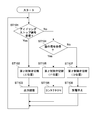
- FIG. 4 is a flowchart illustrating a method for controlling the second drive circuit 52 by the controller 252.
- the controller 252 When the controller 252 receives the idling stop signal S1 via the receiving unit 251, the controller 252 switches the second control valve 24 to the E position. Then, the controller 252 modulates the electric power stored in the second battery 21 via the output adjustment unit 253 to the predetermined voltage, and supplies the modulated voltage to the electric motor 22 (ST101, 102, 103).
- controller 252 when the controller 252 receives the operation signal S2 via the receiving unit 251, the controller 252 switches the second control valve 24 to the F position. Then, the controller 252 closes the contactor 254 and supplies the electric power stored in the second battery 21 to the electric motor 22 as it is (ST104, 105, 106).
- the controller 252 switches the second control valve 24 to the D position when neither the idling stop signal S1 nor the operation signal S2 is received. Then, the controller 252 stops the discharge of the second battery 21 via the output adjustment unit 253, and cuts off the power supply to the electric motor 22 (ST107, 108). At this time, of course, the controller 252 maintains the contactor 254 in an open state (OFF state).
- the mixer truck 100 with the ready-mixed mixer mounted on the mixer drum 1 agitates the ready-mixed mixer in the mixer drum 1 while rotating the mixer drum 1 in the forward direction at a predetermined rotational speed from the concrete plant to the placement site.
- the mixer drum 1 is rotated in the forward direction at the first rotational speed by the first drive circuit 51 using the engine 3 as a drive source. Further, the first battery 5 and the second battery 21 are charged by the generator 4 while the mixer vehicle 100 is traveling.
- the first controller 6 stops idling.
- the function is executed and the driving of the engine 3 is stopped.
- the first control unit 6 further transmits an idling stop signal S1 to the second control unit 25, and switches the first control valve 13 from the A position to the B position.
- the second control unit 25 receives the idling stop signal S1 from the first control unit 6, thereby switching the second control valve 24 to the E position and using the second battery 21 as an electric power source.
- a first control mode for driving with a predetermined voltage is executed (ST101 to ST103).
- the second hydraulic pump 23 discharges pressure oil corresponding to the rotation speed of the electric motor 22 to the hydraulic circuit 14.
- the hydraulic motor 12 is driven by the pressure oil discharged from the second hydraulic pump 23, and rotates the mixer drum 1 in the forward direction at the second rotational speed. As a result, the drive source of the mixer drum 1 is switched from the first drive circuit 51 to the second drive circuit 52.
- the 1st control part 6 detects driving
- the second control unit 25 switches the second control valve 24 to the D position, and stops the discharge of the second battery 21 to stop the driving of the electric motor 22 (ST107, 108).
- the drive source of the mixer drum 1 is switched from the second drive circuit 52 to the first drive circuit 51.
- the mixer drum 1 when a vehicle failure such as an engine trouble occurs, the mixer drum 1 can be rotated in the reverse direction by an input operation of the operation unit 8 by the operator.
- the controller 252 switches the second control valve 24 to the F position and closes the contactor 254.
- 2 control mode is executed (ST104 to 106). Thereby, electric power is supplied from the second battery 21 to the electric motor 22, and the mixer drum 1 can be rotated in the reverse direction.
- the ready-mixed concrete mounted on the mixer drum 1 can be discharged to the outside of the mixer drum 1 based on the input operation of the operation unit 8 by the operator, a large amount of fresh concrete in the mixer drum 1 is condensed. Can be prevented. Thereby, as a first-aid treatment using the limited electric power of the second battery 21, it is possible to appropriately process the raw control in the mixer drum 1.
- a mixer drum of another mixer vehicle is preferable. Thereby, it becomes possible to convey a raw concrete to a construction site or a raw concrete plant by the mixer drum of the other mixer truck.
- the second battery 21 and the electric motor 22 are directly connected via the contactor 254.
- the output of the electric motor 22 can be made larger than in the first control mode in which electric power is supplied from the second battery 21 to the electric motor 22 via the output adjustment unit 253.
- the mixer drum 1 can be stably rotated with relatively large electric power, so that the raw cooking can be discharged efficiently.
- the second control valve 25 since the switching of the second control valve 24 is controlled by the second control unit 25, the second control valve 25 can be controlled even if some failure occurs in the first control unit 6. It becomes possible to execute the mode stably and appropriately.
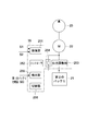
- FIG. 5 is a block diagram showing a schematic configuration of the second control unit according to the second embodiment of the present invention.
- configurations different from those of the first embodiment will be mainly described, and configurations similar to those of the above-described embodiment will be denoted by the same reference numerals, and description thereof will be omitted or simplified.
- the second control unit 35 includes a reception unit 251, a controller 252, an output adjustment unit 253, a contactor 254, a detection unit 255, and a switch 256.
- the receiving unit 251, the output adjusting unit 253, and the contactor 254 are configured in the same manner as in the first embodiment described above, description thereof is omitted here.
- the detection unit 255 is configured to be able to detect the charge amount (SOC: State of Charge) of the first battery 5.
- SOC State of Charge
- the amount of charge is the remaining capacity when the fully charged state (or initial capacity) of the first battery 5 is 100%, and may be measured by current integration, or may be obtained from the first battery 5 acquired in advance. The determination may be made based on the ⁇ V characteristic data.
- the switch 256 is connected to the first battery 5 and the second battery 21, and the power source of the second control unit 35 is transferred from the first battery 5 to the second battery 21 based on control of the controller 252. It is configured to be switchable.
- the controller 252 corresponds to the first control mode or the second control mode based on the idling stop signal S1 and the operation signal S2 received via the receiving unit 251.
- the control of the second control valve 24, the output adjustment unit 253, and the contactor 254 is executed.
- the controller 252 further determines the amount of charge (SOC) of the first battery 5 via the detection unit 255, and the power source of the controller 252 is changed from the first battery 5 to the second battery 21 based on the determination result.
- the switch 256 is controlled to switch to.
- the second control unit 35 uses the first battery 5 as a power source in the first control mode, while the charge amount (SOC) of the first battery in the second control mode. ) Is less than or equal to a predetermined value, and when the amount of charge is less than or equal to the predetermined value, the second battery 21 is used as a power source. Thereby, even when a vehicle failure occurs, a power source for the second control unit 35 can be secured.
- FIG. 6 is a flowchart for explaining an operation example of the controller 252 when the second control mode is executed.
- the controller 252 determines whether or not the second battery 21 is charged from the generator 4 (ST201). This determination can be performed based on, for example, a change in the amount of charge (SOC) of the second battery 21 over time. And when it determines with the 2nd battery 21 being charging, since it can be considered that the generator 4 is operate
- the controller 252 determines whether or not the amount of charge (SOC) of the first battery 5 is greater than or equal to a predetermined value based on the output of the detection unit 255, and closes the contactor 254 if this is greater than or equal to the predetermined value. Then, the second control mode is executed (ST203, 202).
- SOC amount of charge
- the controller 252 determines that the charge amount (SOC) of the first battery 5 is less than the predetermined value, the controller 252 supplies the power source of the second control unit 35 from the first battery 5 via the switch 256. Switch to the second battery 21 (ST204). Thereby, even when the charge amount (SOC) of the first battery 5 is low, a power source for the second control unit 35 can be secured.
- the charge amount (SOC) of the first battery 5 serving as a reference for switching the power source can be set to any value that is determined to prevent the second control unit 35 from operating properly. For example, in this embodiment, when the residual voltage of the first battery 5 is less than 18V, the power source of the second control unit 25 is set to be switched from the first battery 5 to the second battery 21. .
- the controller 252 may be configured to refer to the charge amount (SOC) of the second battery 21 when switching the power source to the second battery 21 described above. In this case, when the charge amount (SOC) of the second battery 21 is less than a predetermined value, the switching of the power source is stopped in order to secure a power source necessary for emergency driving of the mixer drum 1. Also good.
- the electric power stored in the second battery 21 via the contactor 254 so as to bypass the output adjustment unit 253 when the second control mode in the second control unit 25 is executed is the electric motor. 22 to supply.
- the controller 252 may be configured to continuously supply the electric power of the second battery 21 to the electric motor 22 without output modulation in the output adjustment unit 253 when the operation signal S2 is received. Good. Also by such a method, it becomes possible to drive the electric motor 22 with a larger output than in the first control mode.
- a lithium ion battery is used as the second battery 21 in the second drive circuit 52.
- other secondary batteries such as a nickel-hydrogen storage battery and a lead storage battery may be employed. Good.
Landscapes
- Engineering & Computer Science (AREA)
- Mechanical Engineering (AREA)
- Structural Engineering (AREA)
- Health & Medical Sciences (AREA)
- Public Health (AREA)
- Transportation (AREA)
- Preparation Of Clay, And Manufacture Of Mixtures Containing Clay Or Cement (AREA)
- Control Of Vehicle Engines Or Engines For Specific Uses (AREA)
Abstract
Description
上記車体部は、エンジンの動力によって発電する発電機と、アイドリングストップ信号を生成し、上記エンジンを制御する第1の制御部と、ミキサドラムと、オペレータの入力操作により操作信号を生成する操作部と、を有する。
上記第1の駆動回路は、上記ミキサドラムを回転させる液圧モータと、上記エンジンの動力で駆動され上記液圧モータへ液体を供給する第1の液圧ポンプと、を有する。
上記第2の駆動回路は、上記発電機の出力を蓄電する蓄電池と、上記蓄電池に蓄電された電力で駆動される電動モータと、上記電動モータで駆動され上記液圧モータへ液体を供給する第2の液圧ポンプと、第2の制御部と、を有する。
上記第2の制御部は、上記第1の制御部から上記アイドリングストップ信号を受信したときに上記蓄電池に蓄電された電力で上記ミキサドラムを第1の方向に回転させる第1の制御モードを実行する。上記第2の制御部は、上記操作信号を受信したときに上記蓄電池に蓄電された電力で上記ミキサドラムを上記第1の方向とは反対の第2の方向に回転させる第2の制御モードを実行する。
上記第1の受信部は、上記制御部からアイドリングストップ信号を受信可能に構成される。
上記第2の受信部は、上記操作信号を受信可能に構成される。
上記コントローラは、上記アイドリングストップ信号を受信したときに上記蓄電池に蓄電された電力で上記ミキサドラムを第1の方向に回転させる第1の制御モードを実行する。上記コントローラは、上記操作信号を受信したときに上記蓄電池に蓄電された電力で上記ミキサドラムを上記第1の方向とは反対の第2の方向に回転させる第2の制御モードを実行する。
上記ミキサ車に搭載された操作部のオペレータによる入力操作時には、上記蓄電池に蓄電された電力で上記電動モータを第2の出力で駆動することで、上記内容物を排出する方向に上記ミキサドラムが回転させられる。
図1は、本発明の一実施形態に係るミキサ車を示す概略側面図、図2は、上記ミキサ車におけるミキサドラムの駆動回路を示す概略構成図である。
図1に示すように、ミキサ車100は、モルタルやレディミクストコンクリート等(以下、「生コン」という。)を生コン工場から工事現場まで運搬するミキサドラム1を有する。ミキサドラム1は、ミキサ車100の架台2に回転自在に設置される。ミキサ車100は、生コンを運搬するに当たり、生コンの品質劣化および凝結を防止するために、ミキサドラム1を正回転させてミキサドラム1内に取り付けられた螺旋状の複数のブレードで生コンを撹拌する。また、ミキサ車100は、ミキサドラム1を逆回転させることでミキサドラム1内の生コンを排出し、コンクリート打設箇所へ供給する。
続いて、第1の駆動回路51の詳細について説明する。
第2の駆動回路52は、第2のバッテリ21と、電動モータ22と、第2の油圧ポンプ23と、第2の制御弁24と、第2の制御部25とを有する。
次に、ミキサ車100の典型的な動作について説明する。
図5は、本発明の第2の実施形態に係る第2の制御部の概略構成を示すブロック図である。以下、第1の実施形態と異なる構成について主に説明し、上述の実施形態と同様の構成については同様の符号を付しその説明を省略または簡略化する。
Claims (7)
- エンジンの動力によって発電する発電機と、アイドリングストップ信号を生成し、前記エンジンを制御する第1の制御部と、ミキサドラムと、オペレータの入力操作により操作信号を生成する操作部と、を有する車体部と、
前記ミキサドラムを回転させる液圧モータと、前記エンジンの動力で駆動され前記液圧モータへ液体を供給する第1の液圧ポンプと、を有する第1の駆動回路と、
前記発電機の出力を蓄電する蓄電池と、前記蓄電池に蓄電された電力で駆動される電動モータと、前記電動モータで駆動され前記液圧モータへ液体を供給する第2の液圧ポンプと、前記第1の制御部から前記アイドリングストップ信号を受信したときに前記蓄電池に蓄電された電力で前記ミキサドラムを第1の方向に回転させる第1の制御モードを実行し、前記操作信号を受信したときに前記蓄電池に蓄電された電力で前記ミキサドラムを前記第1の方向とは反対の第2の方向に回転させる第2の制御モードを実行する第2の制御部と、を有する第2の駆動回路と
を具備するミキサ車。 - 請求項1に記載のミキサ車であって、
前記第2の制御部は、前記第1の制御モードにおいては前記電動モータを第1の出力で駆動し、前記第2の制御モードにおいては前記電動モータを前記第1の出力よりも大きい第2の出力で駆動する
ミキサ車。 - 請求項2に記載のミキサ車であって、
前記第2の駆動回路は、前記蓄電池と前記電動モータとの間に接続された常開型のスイッチ素子をさらに有し、
前記第2の制御部は、前記第2の制御モードにおいて、前記スイッチ素子を閉成する
ミキサ車。 - 請求項1に記載のミキサ車であって、
前記ミキサドラムを前記第1の方向に回転させる流路を形成する第1の状態と、前記ミキサドラムを前記第2の方向に回転させる流路を形成する第2の状態とを切替可能に構成され、前記第2の液圧ポンプと前記液圧モータとの間に配置された切替弁をさらに具備する
ミキサ車。 - 請求項1に記載のミキサ車であって、
前記車体部は、前記発電機の出力を蓄電する蓄電装置をさらに有し、
前記第2の制御部は、前記第1の制御モードにおいては前記蓄電装置を電力源とし、前記第2の制御モードにおいては前記蓄電装置の充電量が所定値以下であるか否かを判定し、かつ前記充電量が前記所定値以下の場合は前記蓄電池を電力源とする
ミキサ車。 - エンジンの動力によって発電する発電機と、アイドリングストップ信号を生成し、前記エンジンを制御する制御部と、ミキサドラムを回転させる液圧モータと、前記発電機の出力を蓄電する蓄電池と、前記蓄電池に蓄電された電力で駆動される電動モータと、前記電動モータで駆動され前記液圧モータへ液体を供給する液圧ポンプと、オペレータの入力操作により操作信号を生成する操作部と、を有するミキサ車に搭載される制御装置であって、
前記制御部からアイドリングストップ信号を受信可能な第1の受信部と、
前記操作信号を受信可能な第2の受信部と、
前記アイドリングストップ信号を受信したときに前記蓄電池に蓄電された電力で前記ミキサドラムを第1の方向に回転させる第1の制御モードを実行し、前記操作信号を受信したときに前記蓄電池に蓄電された電力で前記ミキサドラムを前記第1の方向とは反対の第2の方向に回転させる第2の制御モードを実行するコントローラと
を具備する制御装置。 - ミキサ車のアイドリングストップ時に、蓄電池に蓄電された電力で電動モータを第1の出力で駆動することで、ミキサドラムの内容物を撹拌する方向に前記ミキサドラムを回転させ、
前記ミキサ車に搭載された操作部のオペレータによる入力操作時に、前記蓄電池の蓄電された電力で前記電動モータを第2の出力で駆動することで、前記内容物を排出する方向に前記ミキサドラムを回転させる
ミキサドラムの回転制御方法。
Priority Applications (2)
| Application Number | Priority Date | Filing Date | Title |
|---|---|---|---|
| AU2015264984A AU2015264984B2 (en) | 2014-05-30 | 2015-05-19 | Mixer vehicle, control device, and rotation control method for mixer drum |
| NZ726458A NZ726458A (en) | 2014-05-30 | 2015-05-19 | Mixer vehicle, control device, and rotation control method for mixer drum |
Applications Claiming Priority (2)
| Application Number | Priority Date | Filing Date | Title |
|---|---|---|---|
| JP2014-112243 | 2014-05-30 | ||
| JP2014112243A JP6410480B2 (ja) | 2014-05-30 | 2014-05-30 | ミキサ車、制御装置およびミキサドラムの回転制御方法 |
Publications (1)
| Publication Number | Publication Date |
|---|---|
| WO2015182433A1 true WO2015182433A1 (ja) | 2015-12-03 |
Family
ID=54698770
Family Applications (1)
| Application Number | Title | Priority Date | Filing Date |
|---|---|---|---|
| PCT/JP2015/064285 Ceased WO2015182433A1 (ja) | 2014-05-30 | 2015-05-19 | ミキサ車、制御装置およびミキサドラムの回転制御方法 |
Country Status (4)
| Country | Link |
|---|---|
| JP (1) | JP6410480B2 (ja) |
| AU (1) | AU2015264984B2 (ja) |
| NZ (1) | NZ726458A (ja) |
| WO (1) | WO2015182433A1 (ja) |
Cited By (1)
| Publication number | Priority date | Publication date | Assignee | Title |
|---|---|---|---|---|
| CN116922578A (zh) * | 2023-04-17 | 2023-10-24 | 厦门豪主意智造科技有限公司 | 一种用于混凝土搅拌车的自动录像系统及其录像方法 |
Families Citing this family (2)
| Publication number | Priority date | Publication date | Assignee | Title |
|---|---|---|---|---|
| JP6701306B1 (ja) * | 2018-11-16 | 2020-05-27 | Kyb株式会社 | ミキサ車 |
| JP7465154B2 (ja) * | 2020-06-10 | 2024-04-10 | カヤバ株式会社 | ミキサ車 |
Citations (4)
| Publication number | Priority date | Publication date | Assignee | Title |
|---|---|---|---|---|
| JP2003301802A (ja) * | 2002-02-06 | 2003-10-24 | Kayaba Ind Co Ltd | ミキサ車 |
| JP3159819U (ja) * | 2010-03-16 | 2010-06-03 | 首都高電気メンテナンス株式会社 | 電動機器を備える車両 |
| WO2012128091A1 (ja) * | 2011-03-24 | 2012-09-27 | カヤバ工業株式会社 | ミキサドラム駆動装置 |
| JP2013193679A (ja) * | 2012-03-22 | 2013-09-30 | Kyb Co Ltd | ミキサドラム駆動装置 |
-
2014
- 2014-05-30 JP JP2014112243A patent/JP6410480B2/ja not_active Expired - Fee Related
-
2015
- 2015-05-19 AU AU2015264984A patent/AU2015264984B2/en not_active Ceased
- 2015-05-19 WO PCT/JP2015/064285 patent/WO2015182433A1/ja not_active Ceased
- 2015-05-19 NZ NZ726458A patent/NZ726458A/en not_active IP Right Cessation
Patent Citations (4)
| Publication number | Priority date | Publication date | Assignee | Title |
|---|---|---|---|---|
| JP2003301802A (ja) * | 2002-02-06 | 2003-10-24 | Kayaba Ind Co Ltd | ミキサ車 |
| JP3159819U (ja) * | 2010-03-16 | 2010-06-03 | 首都高電気メンテナンス株式会社 | 電動機器を備える車両 |
| WO2012128091A1 (ja) * | 2011-03-24 | 2012-09-27 | カヤバ工業株式会社 | ミキサドラム駆動装置 |
| JP2013193679A (ja) * | 2012-03-22 | 2013-09-30 | Kyb Co Ltd | ミキサドラム駆動装置 |
Cited By (1)
| Publication number | Priority date | Publication date | Assignee | Title |
|---|---|---|---|---|
| CN116922578A (zh) * | 2023-04-17 | 2023-10-24 | 厦门豪主意智造科技有限公司 | 一种用于混凝土搅拌车的自动录像系统及其录像方法 |
Also Published As
| Publication number | Publication date |
|---|---|
| AU2015264984A1 (en) | 2016-12-08 |
| JP6410480B2 (ja) | 2018-10-24 |
| AU2015264984B2 (en) | 2018-06-07 |
| JP2015224015A (ja) | 2015-12-14 |
| NZ726458A (en) | 2018-03-23 |
Similar Documents
| Publication | Publication Date | Title |
|---|---|---|
| JP6285246B2 (ja) | ミキサ車、制御装置およびミキサドラムの回転制御方法 | |
| US9878620B2 (en) | Hybrid vehicle | |
| EP1151892B1 (en) | Vehicle with a high voltage power source system and method of controlling the start of such vehicle | |
| US10730509B2 (en) | Fail-safe method for parallel hybrid electric vehicle | |
| CN105102196A (zh) | 搅拌车、驱动系、控制单元和用于操作搅拌车的方法 | |
| JP6410480B2 (ja) | ミキサ車、制御装置およびミキサドラムの回転制御方法 | |
| JP2013028962A (ja) | ハイブリッド型ショベル | |
| JP3692828B2 (ja) | 荷役作業用産業車両 | |
| JP2016158451A (ja) | 電動車両 | |
| JP6527457B2 (ja) | ミキサ車およびミキサ車の制御装置 | |
| CN103270278B (zh) | 开关磁阻发电机启动策略 | |
| JP2003232304A (ja) | ミキサ車 | |
| JP2020063007A (ja) | 車両用バックアップ電源装置 | |
| US20250108710A1 (en) | Techniques for integrating and managing fuel cell systems in fuel cell battery electric vehicles | |
| JP2011122364A (ja) | 作業車両 | |
| JP5977705B2 (ja) | ミキサ車 | |
| JP3815419B2 (ja) | ハイブリッド車両の制御装置および制御方法 | |
| US20130341133A1 (en) | Shovel and method of controlling shovel | |
| JP2007187048A (ja) | エンジンの停止制御装置 | |
| WO2014163502A1 (en) | Hybrid power take-off, vehicle provided therewith and method therefor | |
| JP6344883B2 (ja) | 塵芥収集車の架装物 | |
| JP4285638B2 (ja) | 車両の充電制御装置 | |
| JP2016002828A (ja) | 特種用途自動車用バッテリユニットおよびこれを備えた特種用途自動車 | |
| US20240416820A1 (en) | Truck mixer | |
| JP2012092586A (ja) | 建設機械におけるバッテリの放電防止回路 |
Legal Events
| Date | Code | Title | Description |
|---|---|---|---|
| 121 | Ep: the epo has been informed by wipo that ep was designated in this application |
Ref document number: 15799495 Country of ref document: EP Kind code of ref document: A1 |
|
| NENP | Non-entry into the national phase |
Ref country code: DE |
|
| ENP | Entry into the national phase |
Ref document number: 2015264984 Country of ref document: AU Date of ref document: 20150519 Kind code of ref document: A |
|
| 122 | Ep: pct application non-entry in european phase |
Ref document number: 15799495 Country of ref document: EP Kind code of ref document: A1 |