WO2015182416A1 - Structure de métadonnées de capteur virtuel - Google Patents
Structure de métadonnées de capteur virtuel Download PDFInfo
- Publication number
- WO2015182416A1 WO2015182416A1 PCT/JP2015/064173 JP2015064173W WO2015182416A1 WO 2015182416 A1 WO2015182416 A1 WO 2015182416A1 JP 2015064173 W JP2015064173 W JP 2015064173W WO 2015182416 A1 WO2015182416 A1 WO 2015182416A1
- Authority
- WO
- WIPO (PCT)
- Prior art keywords
- sensor
- data
- virtual
- metadata
- sensing
- Prior art date
Links
Images


Classifications
-
- H—ELECTRICITY
- H04—ELECTRIC COMMUNICATION TECHNIQUE
- H04Q—SELECTING
- H04Q9/00—Arrangements in telecontrol or telemetry systems for selectively calling a substation from a main station, in which substation desired apparatus is selected for applying a control signal thereto or for obtaining measured values therefrom
Definitions
- the present invention relates to a sensor network that uses sensing data, and more particularly to a technology related to the use of sensing data of a virtual sensor.
- M2M Cloud An IT environment called M2M Cloud is attracting attention.
- M2M Machine to Machine
- Machine to Machine refers to a system in which machines with various applications, sizes and capabilities exchange information on a network. By using this information, appropriate control of each machine and real-world situation analysis become possible. Expectations for commercialization are increasing due to the improvement of wireless communication technology that supports M2M, downsizing of machines, and cost reduction.
- M2M cloud An implementation of such M2M technology on a cloud computing environment is called M2M cloud. It provides basic functions required for M2M, such as data collection and storage, processing, and analysis services as applications on the cloud, and makes it available from anywhere. Collective management of data can improve reliability and completeness. Users also benefit from the ability to use collected data and computer resources as needed. Therefore, it is possible to analyze big data and obtain added value without individually constructing a system, and application in a wide range of fields is expected.
- a sensor network is examined. This is a collection of sensing data by installing sensor devices with sensing and communication functions (hereinafter simply referred to as “sensors”) in various places, mobiles, industrial facilities, etc., and networking them. It enables management and seamless use.
- sensors are installed to collect data that the owner himself needs. Therefore, it is often not used except when the owner is collecting data (the sensor itself is not operating or the sensing data is not used even if the sensor is operating). As a result, the distribution of sensing data is low, and even if it is data that is meaningful to a third party, it has been analyzed and used by the sensor owner itself. As a result, redundant investment in facilities and communication with the sensors installed by each cause network congestion.
- IoT Internet of Things
- Patent Document 4 processing data on an application server capable of processing big data to create added value and providing it, and activating transactions of sensing data to bring about economic effects.
- the owner of the sensor can receive compensation for permitting the data user to use the sensor temporarily or providing sensing data.
- there is an advantage for the user because it is not necessary to invest in installing a sensor and the necessary data can be obtained inexpensively.
- the sensor network As described above, the sensor network according to the applicants' study considers that data acquired by machines (sensor devices installed in) installed at various places can be centrally managed and made available. It can be said that it is one form to realize M2M cloud concretely. If a sensor network based on M2M cloud is realized, it will be possible to grasp and use various data from various locations in a suitable form from various places such as data type, acquisition position, and time. Therefore, a wide range of applications are expected from industrial fields such as manufacturing sites and logistics, to life fields such as security, medical care and education, and social infrastructure fields such as smart grids and traffic control systems.
- the applicants are focusing on a technology called "virtual sensor" as one of the elemental technologies for developing and expanding a sensor network.
- a program module that processes sensing data obtained from another sensor and outputs it as new data is prepared as a virtual sensor and provided to the user of the sensor network, the user is a virtual sensor without distinction from the real sensor. Can be used.
- various effects such as improvement of utilization rate of resources (real sensor) and provision of sensing data with new added value can be expected.
- the concept of the virtual sensor itself is already known (see Patent Documents 2, 3 and 4), a mechanism for realizing use of the virtual sensor by another person in the sensor network and circulation of sensing data of the virtual sensor was not considered before.
- the present invention has been made in view of the above problems, and an object of the present invention is to provide a technique for facilitating use of a virtual sensor in a sensor network and circulation of sensing data of the virtual sensor.
- the data structure of the metadata of the virtual sensor according to claim 1 is a metadata of the virtual sensor defining information on a virtual sensor that generates and outputs new sensing data based on input sensing data obtained from another sensor Target region data indicating the position or region where the virtual sensor performs sensing, type data indicating the sensor type of the virtual sensor or the data type of the sensing data output by the virtual sensor, and input sensing data And sensor identification data identifying one or more other sensors to be obtained.
- a “virtual sensor” is a functional module that generates and outputs new sensing data based on input sensing data obtained from another sensor, and is usually not a physical device (in that it has no substance) It is distinguished from the sensor of (referred to as "the real sensor”).
- the "other sensor” may be a real sensor or a virtual sensor.
- the number of “other sensors” (or the number of “input sensing data”) may be one or more.
- the “new sensing data” generated by the virtual sensor may be any data as long as it is data obtained by performing an operation with a predetermined function on the original input sensing data.
- Metadata of virtual sensor is data that describes information related to the virtual sensor (also referred to as an attribute of the virtual sensor), and in the present invention, search or matching of sensors in the sensor network, or new sensing data It assumes metadata that describes the information used for generation.
- virtual sensors and real sensors can be handled without distinction (using the same search conditions) as long as conditions such as the position / region of the sensing target, sensor type, and data type are used. Thereby, the convenience of the user (user or application used) of the sensor can be improved.
- the data structure of the metadata of the virtual sensor according to claim 2 is characterized by further including function identification data for specifying a function for generating the new sensing data from the input sensing data.
- function identification data it is possible to easily specify a function (for example, provided as a program module) necessary to generate new sensing data, and therefore, management and implementation of a virtual sensor can be easily realized.
- the data structure of the metadata of the virtual sensor according to claim 3 is characterized by further including sensor class data indicating whether it is a real sensor or a virtual sensor.
- sensor class data indicating whether it is a real sensor or a virtual sensor.
- the data structure of the metadata of the virtual sensor according to claim 4 is characterized by further including address data indicating a network address of the virtual sensor.
- the data structure of the metadata of the virtual sensor according to claim 5 is characterized by further including target data indicating a sensing target of the virtual sensor.
- the data structure of the metadata of the virtual sensor according to claim 6 is characterized by further including time data indicating a time or a time range in which the virtual sensor performs sensing.
- the data flow control instruction generating device is a sensor side metadata acquisition unit for acquiring sensor side metadata that is information on a sensor that outputs sensing data, and an application for providing a service using the sensing data.
- Application-side metadata acquisition means for acquiring application-side metadata that is information related to the sensor, and a sensor capable of providing sensing data that satisfies the request of the application by matching the sensor-side metadata and the application-side metadata
- the sensor includes: a matching unit for extracting; and an instruction unit for transmitting a data flow control command specifying the sensor extracted by the matching unit and the application to a sensor management apparatus for managing the sensor; Are obtained from other sensors A virtual sensor that generates and outputs new sensing data based on input input sensing data is included, and the sensor-side metadata of the virtual sensor has a data structure according to any one of claims 1 to 6. It is characterized by having.
- the data flow control instruction generation device of the seventh aspect matching is performed between application-side metadata and sensor-side metadata, and an application requiring sensing data and a virtual sensor capable of providing the data And are associated with each other. Then, a data flow control command is transmitted to the device that manages the sensor. This promotes distribution of sensing data in consideration of various conditions, improves services, and benefits both data providers and users.
- Sensor-side metadata indicates information on a sensor and an attribute of sensing data obtained by the sensor
- application-side metadata indicates information on an application itself and an attribute of sensing data required by the application.
- the data flow control command is command information that includes information that specifies a sensor that is a data providing source and an application that is a data using destination, and instructs the data providing source to distribute data to the data using destination. .
- each of a plurality of sensors can be instructed to distribute sensing data to one application.
- sensing data from each of a plurality of sensors can be instructed to be distributed to a plurality of applications. According to such a scheme, it is possible to handle both the real sensor and the virtual sensor in the same framework (without distinction).
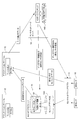
- FIG. 1 is a diagram showing an overall configuration of a sensor network system according to an embodiment of the present invention.
- FIG. 2A is a view showing a data structure of metadata of an actual sensor
- FIG. 2B is a view showing an example of metadata of the actual sensor.
- FIG. 3A is a diagram showing a data structure of metadata of a virtual sensor
- FIG. 3B is a diagram showing an example of metadata of the virtual sensor.
- FIG. 4A is a diagram showing a data structure of metadata of sensing data
- FIG. 4B is a diagram showing an example of metadata of sensing data.
- FIG. 5 is a diagram showing the data structure of application-side metadata.
- the present invention is applied to a sensor network system using an M2M cloud. If such a mechanism is realized, the desired information can be easily accessed by anyone from a wide variety of information obtained from a large number of sensors (both real and virtual sensors can be mixed) existing on the sensor network. It is expected that it will be possible to acquire data, and promote the effective use of sensors (resources), as well as the distribution of sensing data from data providers to data users.
- This system is applicable to various applications such as traffic control systems based on sensing data of traffic conditions, weather forecasting systems based on sensing data of the environment, various analysis systems using big data, and the like.
- This sensor network system is a system for controlling the distribution of sensing data from a data provider to a data utilization destination, and generally, a plurality of real sensors 10 as data providers, a sensor network adapter 11, and the like.
- M2M cloud server in charge of multiple application servers 12 as data use destinations, collection of sensing data from data provision sources, accumulation, analysis of sensing data, delivery of sensing data and analysis results to use destinations, etc. 13, and a sensor network server 14 in charge of matching between a data provider and a user.
- the blocks are communicably connected by a wide area network such as the Internet or a LAN.
- the network is not limited to a single network, and may be considered as a conceptual one in which a plurality of networks having various communication methods and topologies are connected to each other.
- any form of network may be used as long as transmission and reception of sensing data and transmission and reception of data such as metadata and data flow control instruction related to distribution of sensing data can be realized.
- the actual sensor 10 is a device that detects a physical quantity to be sensed and its change, and records or outputs it as sensing data.
- a sensor having a physical entity is referred to as a “real sensor” to distinguish it from a virtual sensor (in some cases, a virtual sensor may be simply referred to as a “sensor” when it is not necessary to distinguish between real sensors).
- the actual sensor 10 includes, for example, an image sensor (such as a monitoring camera), a temperature sensor, a humidity sensor, an illuminance sensor, a force sensor, a sound sensor, an RFID sensor, an infrared sensor, an attitude sensor, a rainfall sensor, a radioactivity sensor, a gas sensor, and an acceleration.
- An input system including a device for inputting text with a sensor, a gyroscope, a GPS sensor, a smartphone, etc., and an Input Method corresponds to this.
- the sensor network system of the present embodiment can use any type of sensor including the sensor exemplified here.
- a large number of sensors have already been installed in various places in the world, such as factory FA, production management, urban traffic control, environmental measurement such as weather, healthcare, crime prevention, etc. It is also possible to connect to this system.
- the sensor network system may be configured of only one type of sensor, or a plurality of types of sensors may be mixed.
- the sensor network adapter 11 is a device that is physically or electrically connected to one or more real sensors 10 and acquires sensing data from the real sensors 10. Further, the sensor network adapter 11 has a function of performing predetermined processing on sensing data by an information processing apparatus such as a CPU.
- the sensor network adapter 11 has a communication function with the outside, and can communicate with the M2M cloud server 13, the application server 12, the sensor network server 14, and the like via a network.
- portable terminals such as smartphones, tablet terminals, and mobile PCs have built-in sensors such as image sensors, GPS sensors, acceleration sensors, and microphones, and a function or network communication function that processes and outputs data obtained by each sensor have. Therefore, these portable terminals are examples of devices in which the actual sensor 10 and the sensor network adapter 11 are physically integrated.
- the M2M cloud server 13 is a server responsible for management, analysis, and distribution of sensing data.
- the hardware can be configured by a general-purpose computer including an information processing device (CPU), a memory, an auxiliary storage device (HDD or the like), a communication device, an input device, a display device, and the like.
- the sensor network adapter 11 in various places receives access via a network, receives a large amount of sensing data, stores it in a database, and provides necessary data to the application server 12 that is the data utilization destination. Performance required to perform a large amount of data processing.
- the M2M cloud server 13 includes a sensing data DB (database) 130, a virtual sensor DB 131, and the like.
- the sensing data DB 130 is a database that accumulates and manages sensing data collected from the sensor network adapter 11.
- the virtual sensor DB 131 is a database in which a plurality of virtual sensors are registered.
- the virtual sensor is a functional module that processes, analyzes, etc. input sensing data obtained from other sensors to generate new sensing data.
- the virtual sensor is physically composed of a combination of one or more sensors (sensors from which input sensing data is acquired) and a virtual sensor function that is a program for processing and analyzing input sensing data, etc. It is distinguished from the real sensor 10 in that it is not a device.
- the sensor network system of the present embodiment is characterized in that it enables not only the real sensor 10 but also the use of a virtual sensor and the circulation of sensing data generated and output by the virtual sensor.
- the information required by a certain application server 12 is “the speed of a vehicle passing through a certain intersection X”. If there is a vehicle speed sensor installed at the intersection X among the actual sensors 10 connected to the sensor network, sensing data obtained by the vehicle speed sensor may be provided to the application server 12. However, there may be no real sensor that completely matches the application server 12 requirements. In such a case, if cameras are installed on the entrance side and the exit side of the intersection X, based on image data and time information obtained from the entrance side camera and the exit side camera, The time it takes for the vehicle to travel from the entrance to the exit of the intersection can be calculated and from that the speed of the vehicle can be estimated.
- the virtual sensor function that calculates the speed of the passing vehicle by dividing the distance by the difference can create a virtual sensor that achieves the same function as the vehicle speed sensor.
- the application server 12 is a server apparatus in which various application programs using sensing data are installed, performs arithmetic processing according to a request, and returns the result.
- the application server 12 can also be configured by a general-purpose computer including an information processing device (CPU), a memory, an auxiliary storage device (HDD or the like), a communication device, an input device, a display device, and the like.
- the application server 12 is installed by a user of sensing data, and various applications are assumed according to the application and purpose.
- traffic conditions at each point are collected from a sensor installed on a road, an on-vehicle terminal mounted on a vehicle traveling on a road, a smartphone of a driver, etc. to generate a congestion map.
- An application provided to a business operator etc. using congestion information can be considered.
- image data captured while traveling with a smartphone or in-vehicle camera is collected, and a video delivery application provided to users who want to know the situation at each point, travel route of the vehicle is searched based on congestion information, etc.
- a variety of things are considered such as a route search application to be used, an application that estimates statistical data of attributes (sex, age group, etc.) of passersby from images of cameras installed in specific places and provides them as data for various surveys.
- the user of the sensor network can directly acquire the sensing data of each sensor, and not only by specifying the application and requesting processing, without being aware of each sensor Desired information can be obtained.
- the sensor network server 14 is a server device that manages a sensor related to a sensor network.
- the sensor network server 14 can also be configured by a general-purpose computer including an information processing device (CPU), a memory, an auxiliary storage device (HDD or the like), a communication device, an input device, a display device and the like.
- the sensor network system is for networking a large number (or various types) of sensors and enables collection and use of sensing data, but in this embodiment, the owner (data provider) of the sensor And other data users (application servers) are assumed to be provided with sensing data to obtain compensation. This offers the benefit of a profit opportunity for the sensor owner (data provider) and an inexpensive data acquisition for the user.
- the sensor network server 14 is a server device that mediates transactions of such sensing data, performs matching between a data provider and a data user, and realizes appropriate distribution of sensing data.
- sensor side metadata describing information (attributes) related to sensors is prepared for all sensors (including real sensors and virtual sensors) registered in the sensor network, and an application that is a data user is concerned.
- Use application-side metadata that describes information (attributes). Then, the metadata providing source (sensor) and the use destination (application) are appropriately matched by comparing the metadata.
- an event in which the sensor-side metadata DB 140 in which sensor-side metadata is registered is installed in the sensor network server 14 and the sensor network server 14 receives application-side metadata from the application server 12 With this as a trigger, matching between the application-side metadata and the sensor-side metadata read from the sensor-side metadata DB 140 is performed.
- the sensor-side metadata DB may be installed separately from the sensor network server 14 (for example, on the cloud).
- an event from the application side for example, reception of application-side metadata
- an event from the sensor side for example, notification of updating sensing data
- an application-side metadata DB in which application-side metadata of each application server 12 is registered in advance may be provided in the sensor network server 14.
- FIG. 2A shows an example of a data structure of metadata of an actual sensor.
- attribute information of sensor In the metadata of the real sensor, "1. attribute information of sensor”, “2. attribute information of sensing target”, “3. attribute information of sensing target area”, “4. attribute information of sensing operation” as major items "Is included.
- Attribute information of sensor is data indicating an attribute of the sensor device itself, and “sensor class”, “sensor class No.”, “sensor type”, “position / attitude of sensor”, “possession of sensor” It includes data such as person ID, sensor ID and address, and sensor operation history information.
- the “sensor class” is information indicating whether the sensor is a real sensor or a virtual sensor. For example, a flag indicating a sensor class is described, such as “0” in the case of an actual sensor and “1” in the case of a virtual sensor.
- Sensor class No.” is the sensor class No. of the corresponding sensor.
- Information indicating Sensor class No. Is a number indicating the type of sensor, and in the present system, a number is assigned in advance for each type.
- the speed sensor is assigned “001", the acceleration sensor “002”, the jerk sensor “003", the image sensor “004", and so on.
- Sensor class No. Is not a number but may be denoted by a code.
- the sensor class No. between the real sensor and the virtual sensor E.g., the speed sensor of the real sensor is "RC001”, the speed sensor of the virtual sensor is "VC001").
- “Sensor type” is also information indicating the type of sensor, and is described not by a number but by a character string such as “speed sensor”, “acceleration sensor”, and the like.
- the “position / orientation of sensor” is information indicating the installation position (for example, latitude / longitude information) of the sensor and the direction (for example, “for north”) of the sensor.
- Sensor owner ID is information for identifying the owner of the sensor. It is used when acquiring the payment destination for sensor usage and the contact address in case of sensor failure.
- the “sensor ID, address” is information (ID) for identifying the sensor in the sensor network and information (address) indicating a network address for accessing the sensor.
- the network address for example, an IP address, a MAC address, a URI (Uniform Resource Identifier), etc. can be used.
- the “operation history information of the sensor” is information for recording a log of an error that has occurred in the sensor. This is used, for example, for the purpose of evaluating the reliability of sensors and sensing data.
- Attribute Information of Sensing Target is data indicating an attribute related to the sensing target (that is, what to sense), such as “type of target”, “physical attribute of target”, “ID of target”, etc. Contains data. It is not necessary to describe all these data. For example, when “car” which is a general object is a sensing target, “car” is described in “type of target”, and other data are left blank. The physical attribute can be used for narrowing down the sensing targets. For example, when “red” is described in the “physical attribute of the target”, the “red car” is the sensing target. If the specific object is not an unspecified object but the specific object is a sensing target (for example, a car having a vehicle number of xxxx), the ID for identifying the specific object may be described in the “target ID”.
- Attribute information of sensing target area is data indicating a space and time in which the sensor performs sensing, and includes data of “position range” and “time range”.
- the “position range” is target area data indicating a position or an area where sensing is performed. For example, data indicating position coordinates of one point in space (for example, latitude and longitude information) may be used, or data indicating an area having a spread (area) (for example, position coordinates of each vertex of a polygon area, center point Location coordinates and radius information, location names, etc.).
- the position of a sensor and “position range” in "1. attribute information of a sensor” do not necessarily correspond.
- the “time range” is time data indicating the time during which the sensor performs sensing. For example, the time at which sensing is performed may be described as “8:00, 10:00, 12:00”, or the time during which the sensor is operating as “8:00 to 15:00”. You may describe the range.
- Attribute information of sensing operation is data indicating an operating condition of the sensor, and includes “sensing control parameter” and “sampling specification, quantization specification”.
- the contents described in the “sensing control parameter” vary depending on the sensor type. For example, in the case of an image sensor (camera), photographing conditions such as shutter speed and exposure can be described, and in the case of active sensing where photographing is performed with illumination, conditions such as the intensity of illumination light are described. It is also good.
- sampling specification, quantization specification acquisition conditions of sensing data (for example, sampling period (data acquisition period), resolution, resolution, number of bits of data, etc.) can be described.
- FIG. 2B is an example of metadata describing information of a certain real sensor.
- this real sensor is an image sensor that is installed at the Hanzomon intersection in Chiyoda-ku, Tokyo and can detect a red car passing the Hanzomon intersection from 9:00 to 21:00.
- the owner of the image sensor and the access destination on the network can be specified.
- the data structure of the metadata of the virtual sensor is a structure that inherits (includes) the metadata of the real sensor so that the real sensor and the virtual sensor can be handled basically without distinction.
- the data structure of the virtual sensor will be described below.
- attribute information of sensor As the major items of the virtual sensor metadata, "1. attribute information of sensor”, “2. attribute information of sensing target”, “3. attribute information of sensing target area”, “4. attribute information of sensing operation” “5. Real sensor attribute information” and “6. Function attribute information” are included.
- the four items “1. Sensor attribute information”, “2. Sensing target attribute information”, “3. Sensing target area attribute information”, and “4. Sensing operation attribute information” are shown in FIG. 2A. It is the same as the data structure of real sensor metadata. However, the person who created and registered the virtual sensor (for example, the virtual sensor function is programmed and the attribute information of the sensing operation is set to “owner ID of sensor” in “1. Attribute information of sensor”, virtual sensor Person who sets and registers other metadata of) is described as the owner. The owner of the virtual sensor and the owner of the real sensor that constitutes the virtual sensor do not have to be the same person.
- Position and posture of sensor may be blank, or data of the installation position and posture of an actual sensor that constitutes a virtual sensor may be described.
- the “sensor address” describes the network address of the server (in this embodiment, the M2M cloud server) responsible for managing and controlling virtual sensors.
- the “position range” in “3. attribute information of the sensing target area” is the position or area where the virtual sensor performs virtual sensing (that is, the position or area to which new sensing data output by the virtual sensor is related) Describe the target area data indicating.
- a position range including the sensing target area of each of the plurality of real sensors can be taken as the sensing target region of the virtual sensor.
- the sensing target area of the actual sensor and the virtual sensor such as a virtual sensor that predicts the traffic on the Metropolitan Expressway after a predetermined time
- the sensing target area may be different.
- “5. Real sensor attribute information” and “6. Function attribute information” are information included only in the virtual sensor metadata.
- “5. Real sensor attribute information” is sensor identification data for specifying another sensor from which the virtual sensor acquires input sensing data.
- the "attribute information of real sensor” includes “sensor type” and “sensor ID”.
- the sensor of the data acquisition destination can be uniquely identified by "Sensor ID”.
- Sensor ID When the virtual sensor uses a plurality of input sensing data, "5. Real sensor attribute information” is repeatedly described for each input sensing data.
- sensor ID of a virtual sensor can also be described in "sensor ID.” This is because other virtual sensors can also generate new sensing data based on the sensing data generated by the virtual sensor.
- Function attribute information is function identification data for specifying a virtual sensor function used to generate new sensing data from input sensing data.
- the “function attribute information” includes “function ID”. It is possible to call a virtual sensor function (program module) registered in the virtual sensor DB 131 by the “function ID”.
- FIG. 3B is an example of metadata describing information of a certain virtual sensor.
- this virtual sensor is a speed sensor capable of detecting the speed of a red car passing a Hanzomon intersection from 9:00 to 21:00.
- FIG. 4A is an example of a data structure of metadata of sensing data.
- the metadata of sensing data is data describing the attributes of individual sensing data obtained by a real sensor or a virtual sensor. Metadata of sensing data includes “ID of manager or owner”, “access authority range”, “accuracy, unit system”, “reliability”, “available range”, “system of consideration for use”, Data such as “ID of used sensor” and “sensing data ID” are included.
- the “manager or owner ID” is identification information for identifying a person who controls or owns the right of the sensing data. It may coincide with the "owner ID” of the sensor that has output the sensing data.
- the “access right range” is information indicating the range of the right to allow the use of the sensing data. For example, if the access authority range is “0”, anyone can use it, if “1”, it can be used to the person of the first authority level, and if it is “2”, it can be used to the person of the second authority level It is used like .... “Precision, unit system” is information indicating the accuracy (for example, the number of significant digits) of the sensing data and the unit system.
- the “reliability” is information indicating the reliability of the sensing data (for example, the probability that the value of the sensing data is within the allowable error range).
- “Available range” is information indicating the purpose of use of the sensing data (for example, limited to academic use, commercial use is not possible, etc.).
- the “system of consideration for use” is information indicating the setting of the fee for payment when the sensing data is used. For example, a number of charge systems are prepared in advance, such as whether it is a usage charge or a fixed charge, or a charge for each purpose of use, and information for specifying a charge system is described in the "system of payment for use”.
- the “ID of the used sensor” is the “sensor ID” of the sensor that has output the sensing data.
- "Sensing data ID” is identification information for uniquely identifying the sensing data.
- FIG. 4B is an example of metadata describing information of certain sensing data. By referring to this metadata, it is possible to obtain information to be a reference when judging whether to use the sensing data.
- the metadata of sensing data can be used, for example, when performing data search or matching between a provider and a user at the level of sensing data. Therefore, if the system specification is limited to search and matching at the sensor level, metadata of sensing data is not essential.
- metadata may be set for only some of the sensing data, or sensing data groups grouped under predetermined conditions instead of individual sensing data ( For example, one metadata may be set for one day's sensing data group of a certain sensor, sensing data group obtained from a plurality of sensors existing in a certain region, and so on.
- FIG. 5 shows an example of the data structure of application-side metadata.
- the application-side metadata is data that describes the conditions of the sensing data required by the application (the attributes of the sensor and sensing data) “1. Attribute information of required sensors”, “2. Sensing target required Attribute information of ", 3. attribute information of required sensing target area”, “4. attribute information of required sensing operation”, “5. management attribute of required sensing data” and attributes of the application itself And “6. Metadata of the application itself”, which is data describing.
- Attribute information of required sensor to “5. Management attribute of required sensing data” corresponds to the data of the same name shown in FIG. 2A, FIG. 3A and FIG. 4A. doing. That is, metadata related to the condition of sensing data required by the application is “Sensor Owner ID”, “Sensor ID”, “Administrator or Owner ID”, and the like from the items of sensor side metadata, It has a data structure in which items unique to the sensor or sensing data such as “sensing data ID” are excluded.
- the metadata of the application itself includes data such as "file name of application”, “address of server on which application file runs”, “definition of sensor side event that enables activation of the application” .
- "File name of application” is the name of the application program installed on the application server, and "address of the server on which the application file operates” is the network address (IP address etc.) of the application server .
- An application can be identified by specifying these two.
- the “definition of a sensor-side event that enables activation of the application” is information that defines an event code (tag name) to be delivered to the application. For example, an event code (tag name) corresponding to the value of sensing data can be defined by a function or a table.
- the car navigation application installed on the smartphone is an image of a position slightly ahead (for example, 1 km ahead, 10 minutes later) according to the movement of the owner of the smartphone.
- An embodiment for presenting information will be described. Such a function can be used when grasping the situation in the traveling direction of the vehicle and determining whether to change the course.
- a smartphone corresponds to the application server 12 shown in FIG. 1
- a car navigation application corresponds to an application using sensing data.
- crew of the other vehicle possesses, the sensor installed in infrastructures, such as a road and a signal, etc. are assumed.
- a route guidance request is input to a car navigation application of a smartphone possessed by a driver who encounters a traffic jam.
- the car navigation application generates application-side metadata describing conditions of sensing data required to collect information necessary for route guidance, and transmits the application-side metadata to the sensor network server 14. For example, based on the current position and traveling direction of the vehicle and the destination information set in the car navigation application, an area requiring sensing data (for example, a circular area including the current position and the destination) is calculated. It is possible to acquire data relating to road conditions in the area, and describe conditions for extracting sensors that can be used at the current time in application-side metadata.
- the sensor network server 14 matches the received application-side metadata with the sensor-side metadata registered in the sensor-side metadata DB 140, and specifies a sensor that can provide sensing data required by the application.
- Sensor side metadata of both the real sensor and the virtual sensor are registered in the sensor side metadata DB 140.
- Matching of metadata is all or part of the data described in the items from “1. Required sensor attribute information” to “5. Required sensing data management attribute” shown in FIG. 5
- Required sensing data management attribute shown in FIG. 5
- the sensor network server 14 refers to the application side metadata and the extracted sensor side metadata to obtain sensor data
- a data flow control command specifying a sensor as a providing source and an application as a data use destination is generated.
- the data flow control command includes at least information (for example, sensor ID, address, etc.) for specifying a sensor that is a data providing source, and information for specifying an application that is a data use destination (for example, address of an application server) , App file name, tag name etc.).
- all or a subset of application-side metadata and sensor-side metadata may be included in the data flow control command.
- the sensor network server 14 sends this data flow control command to the device that manages the sensor.
- a data flow control command is sent to the sensor network adapter 11 managing the actual sensor, and in the case of a virtual sensor, an M2M cloud server 13 having a management function of a virtual sensor. Send data flow control command to.
- the sensor network adapter 11 having received the data flow control command acquires sensing data from the sensor specified in the data flow control command, adds a predetermined header to generate packet data, and passes the packet data via the network Send to the application at.
- the sensing data may be, for example, position information and speed information of another vehicle, or video information captured by another vehicle or a camera on a road.
- the M2M cloud server 13 that has received the data flow control command executes necessary processing for the virtual sensor specified in the data flow control command.
- input sensing data required for processing of the virtual sensor is acquired from the sensing data DB 130, and a virtual sensor function is called from the virtual sensor DB 131.
- new sensing data is generated based on the input sensing data. For example, processing of calculating traffic conditions of a plurality of routes based on video data of a plurality of cameras scattered in an area 1 km ahead of the traveling direction of the vehicle and outputting as new sensing data is assumed.
- the generated new sensing data is transmitted to the application as packet data with a predetermined header.
- sensor ID used as an acquisition place of input sensing data, and function ID which specifies a virtual sensor function to call it describes in sensor side metadata.
- the M2M cloud server 13 can obtain the sensor ID and the function ID from the data flow control command.
- a virtual sensor definition database similar to the sensor-side metadata DB 140 of the sensor network server 14 may be provided on the side of the M2M cloud server 13 as well.
- the M2M cloud server 13 uses the sensor ID as a key, and IDs of other sensors constituting the virtual sensor from the virtual sensor definition database. And function ID etc.
- the system described above unlike the conventional IoT in which the sensor and the user are fixed, it is possible to optimize the information distribution on the network, including the processing of the usage charge regarding transmission and reception of sensing data. Therefore, new value-added information is generated in the application server, and sensor resources are effectively used. For example, when sensor information such as a moving vehicle is required, information can be seamlessly provided in a system in which components are fluid.
- an advantageous sensor can be selected based on conditions such as usage consideration, or the accuracy can be increased using all the plurality of sensors.
- sensing data processing can be performed with various particle sizes according to the characteristics of sensors and applications, so that a highly versatile data base can be formed.
- the search and matching of the virtual sensor based on conditions such as position / area of sensor target, sensor type and data type are performed using the metadata. It makes it possible.
- the virtual sensor and the real sensor can be handled without distinction (using the same search condition) as long as conditions such as the position / area of the sensing target, sensor type and data type are used. Thereby, the convenience of the user (user or application used) of the sensor can be improved.
- the data structure of the metadata illustrated in the above embodiment is an example, and it is not necessary to include all the illustrated items, but may include items other than the illustrated items.
- the configuration of the sensor network system shown in FIG. 1 is only an example, and it is also possible to use the metadata according to the present invention in systems of other configurations.
Landscapes
- Engineering & Computer Science (AREA)
- Computer Networks & Wireless Communication (AREA)
- Telephonic Communication Services (AREA)
- Selective Calling Equipment (AREA)
Abstract
L'invention concerne une structure de données de métadonnées de capteur virtuel qui définit des informations concernant un capteur virtuel qui génère et sort de nouvelles données de détection sur la base de données de détection d'entrée obtenues à partir d'un autre capteur. La structure de données comprend : des données de région cible qui indiquent la position ou la région dans laquelle le capteur virtuel doit réaliser une détection; des données de classification qui indiquent la classification du capteur virtuel ou la classification des données de détection sorties par le capteur virtuel; et des données d'identification de capteur qui spécifient au moins un autre capteur qui obtient les données de détection d'entrée.
Applications Claiming Priority (2)
| Application Number | Priority Date | Filing Date | Title |
|---|---|---|---|
| JP2014108373A JP2015226102A (ja) | 2014-05-26 | 2014-05-26 | 仮想センサのメタデータ構造 |
| JP2014-108373 | 2014-05-26 |
Publications (1)
| Publication Number | Publication Date |
|---|---|
| WO2015182416A1 true WO2015182416A1 (fr) | 2015-12-03 |
Family
ID=54698753
Family Applications (1)
| Application Number | Title | Priority Date | Filing Date |
|---|---|---|---|
| PCT/JP2015/064173 WO2015182416A1 (fr) | 2014-05-26 | 2015-05-18 | Structure de métadonnées de capteur virtuel |
Country Status (2)
| Country | Link |
|---|---|
| JP (1) | JP2015226102A (fr) |
| WO (1) | WO2015182416A1 (fr) |
Cited By (7)
| Publication number | Priority date | Publication date | Assignee | Title |
|---|---|---|---|---|
| JP2017111501A (ja) * | 2015-12-14 | 2017-06-22 | オムロン株式会社 | データフロー制御装置およびデータフロー制御方法 |
| JP6468377B1 (ja) * | 2018-02-13 | 2019-02-13 | オムロン株式会社 | 出力管理装置、出力管理方法及びプログラム |
| JP2019139545A (ja) * | 2018-02-13 | 2019-08-22 | オムロン株式会社 | 出力管理装置、出力管理方法及びプログラム |
| EP3550813A4 (fr) * | 2016-12-02 | 2019-12-04 | Omron Corporation | Dispositif de mise en correspondance, terminal, système de réseau de capteurs, procédé de mise en correspondance, et programme de mise en correspondance |
| CN110582759A (zh) * | 2017-06-06 | 2019-12-17 | 欧姆龙株式会社 | 得分计算单元、检索装置、得分计算方法和得分计算程序 |
| CN111602408A (zh) * | 2018-02-13 | 2020-08-28 | 欧姆龙株式会社 | 候选提取装置、候选提取方法及程序 |
| US20230327957A1 (en) * | 2020-08-27 | 2023-10-12 | Siemens Aktiengesellschaft | Centralized management of data flow maps for distributed edge node deployment |
Families Citing this family (15)
| Publication number | Priority date | Publication date | Assignee | Title |
|---|---|---|---|---|
| JP2017135508A (ja) * | 2016-01-26 | 2017-08-03 | コネクトフリー株式会社 | ネットワークシステム |
| JP6153636B1 (ja) * | 2016-02-12 | 2017-06-28 | 株式会社クレスコ | 通信システム |
| JP6372508B2 (ja) * | 2016-03-15 | 2018-08-15 | オムロン株式会社 | データフロー制御装置およびデータフロー制御方法 |
| JP6811468B2 (ja) * | 2016-06-15 | 2021-01-13 | 国立大学法人 東京大学 | 情報処理装置、データ検索方法、プログラム、データ構造及びデータ処理システム |
| JP6390692B2 (ja) | 2016-12-15 | 2018-09-19 | オムロン株式会社 | データ配信システム、指示装置、データ配信装置、センサ管理装置、データ配信方法、およびプログラム |
| JP6380517B2 (ja) * | 2016-12-15 | 2018-08-29 | オムロン株式会社 | 制御装置、センサ管理装置、制御方法、センサ管理方法およびプログラム |
| WO2018179364A1 (fr) * | 2017-03-31 | 2018-10-04 | 株式会社日立製作所 | Système informatique et procédé de contrôle de flux données |
| WO2019026454A1 (fr) * | 2017-08-02 | 2019-02-07 | オムロン株式会社 | Dispositif de génération de données, procédé de génération de données, et programme |
| JP6525043B2 (ja) * | 2017-08-02 | 2019-06-05 | オムロン株式会社 | データ生成装置、データ生成方法及びプログラム |
| JP6852794B2 (ja) | 2017-08-08 | 2021-03-31 | 日本電気株式会社 | データ授受制御システム、方法およびプログラム |
| KR102031843B1 (ko) * | 2017-12-29 | 2019-10-15 | 주식회사 비스텔 | 가상의 센서 데이터를 생성하는 방법 및 장치 |
| JP6481787B1 (ja) * | 2018-02-14 | 2019-03-13 | オムロン株式会社 | デバイス選択装置、データセット選択装置、デバイス選択方法及びプログラム |
| JP7000934B2 (ja) * | 2018-03-14 | 2022-01-19 | トヨタ自動車株式会社 | データ収集システム、データ収集方法、メッセージ配信制御装置、及び、メッセージ配信制御方法 |
| JP2019168267A (ja) * | 2018-03-22 | 2019-10-03 | パイオニア株式会社 | データ構造、情報処理装置、データ通信方法、プログラム及び記憶媒体 |
| US11741077B2 (en) * | 2018-09-28 | 2023-08-29 | Mitsubishi Electric Corporation | Server device, data distribution system, data provision method, and recording medium |
Citations (2)
| Publication number | Priority date | Publication date | Assignee | Title |
|---|---|---|---|---|
| JP2008217612A (ja) * | 2007-03-06 | 2008-09-18 | Nippon Telegr & Teleph Corp <Ntt> | センサデータ制御システム及びセンサデータ制御方法 |
| JP2013162258A (ja) * | 2012-02-03 | 2013-08-19 | Omron Corp | 無線通信ノード、ゲーム実行装置、仲介装置 |
-
2014
- 2014-05-26 JP JP2014108373A patent/JP2015226102A/ja active Pending
-
2015
- 2015-05-18 WO PCT/JP2015/064173 patent/WO2015182416A1/fr active Application Filing
Patent Citations (2)
| Publication number | Priority date | Publication date | Assignee | Title |
|---|---|---|---|---|
| JP2008217612A (ja) * | 2007-03-06 | 2008-09-18 | Nippon Telegr & Teleph Corp <Ntt> | センサデータ制御システム及びセンサデータ制御方法 |
| JP2013162258A (ja) * | 2012-02-03 | 2013-08-19 | Omron Corp | 無線通信ノード、ゲーム実行装置、仲介装置 |
Non-Patent Citations (1)
| Title |
|---|
| SHUHEI MATSUO: "Sensor search with spatial information and support by showing similar parameter for building sensor context: Sensor Service Binder 2.0", IEICE TECHNICAL REPORT, vol. 109, no. 327, 3 December 2009 (2009-12-03), pages 59 - 64 * |
Cited By (16)
| Publication number | Priority date | Publication date | Assignee | Title |
|---|---|---|---|---|
| WO2017104287A1 (fr) * | 2015-12-14 | 2017-06-22 | オムロン株式会社 | Dispositif et procédé de commande de flux de données |
| US10896347B2 (en) | 2015-12-14 | 2021-01-19 | Omron Corporation | Dataflow control apparatus and dataflow control method for metadata matching and device extraction |
| JP2017111501A (ja) * | 2015-12-14 | 2017-06-22 | オムロン株式会社 | データフロー制御装置およびデータフロー制御方法 |
| EP3550813A4 (fr) * | 2016-12-02 | 2019-12-04 | Omron Corporation | Dispositif de mise en correspondance, terminal, système de réseau de capteurs, procédé de mise en correspondance, et programme de mise en correspondance |
| US10708719B2 (en) | 2016-12-02 | 2020-07-07 | Omron Corporation | Matching device, terminal, sensor network system, matching method, and matching program |
| CN110582759B (zh) * | 2017-06-06 | 2024-01-12 | 欧姆龙株式会社 | 得分计算单元、检索装置、得分计算方法和得分计算程序 |
| CN110582759A (zh) * | 2017-06-06 | 2019-12-17 | 欧姆龙株式会社 | 得分计算单元、检索装置、得分计算方法和得分计算程序 |
| WO2019159489A1 (fr) * | 2018-02-13 | 2019-08-22 | オムロン株式会社 | Dispositif de gestion de sortie, procédé de gestion de sortie et programme |
| JP2019138789A (ja) * | 2018-02-13 | 2019-08-22 | オムロン株式会社 | 出力管理装置、出力管理方法及びプログラム |
| WO2019159490A1 (fr) * | 2018-02-13 | 2019-08-22 | オムロン株式会社 | Dispositif de gestion de sortie, procédé de gestion de sortie et programme |
| CN111602408A (zh) * | 2018-02-13 | 2020-08-28 | 欧姆龙株式会社 | 候选提取装置、候选提取方法及程序 |
| JP2019139545A (ja) * | 2018-02-13 | 2019-08-22 | オムロン株式会社 | 出力管理装置、出力管理方法及びプログラム |
| CN111602408B (zh) * | 2018-02-13 | 2022-04-29 | 欧姆龙株式会社 | 候选提取装置、候选提取方法及程序 |
| JP6468377B1 (ja) * | 2018-02-13 | 2019-02-13 | オムロン株式会社 | 出力管理装置、出力管理方法及びプログラム |
| US11927928B2 (en) | 2018-02-13 | 2024-03-12 | Omron Corporation | Output management apparatus, output management method, and program |
| US20230327957A1 (en) * | 2020-08-27 | 2023-10-12 | Siemens Aktiengesellschaft | Centralized management of data flow maps for distributed edge node deployment |
Also Published As
| Publication number | Publication date |
|---|---|
| JP2015226102A (ja) | 2015-12-14 |
Similar Documents
| Publication | Publication Date | Title |
|---|---|---|
| WO2015182416A1 (fr) | Structure de métadonnées de capteur virtuel | |
| Liu et al. | A survey of mobile crowdsensing techniques: A critical component for the internet of things | |
| US10956758B2 (en) | Method and system for providing auto space management using virtuous cycle | |
| AU2017399007B2 (en) | Mobility gene for trajectory data | |
| JP6465012B2 (ja) | データフロー制御装置およびデータフロー制御方法 | |
| EP3385852B1 (fr) | Appareil de commande de flux de données et procédé de commande de flux de données | |
| CA3061281C (fr) | Verification de donnees de detection au moyen d'incorporations | |
| EP3877867A1 (fr) | Systèmes et procédés de gestion de données de véhicule | |
| CN113439269A (zh) | 用于处理车辆事件数据以进行行程分析的系统和方法 | |
| AU2017399008A1 (en) | Mobility gene for visit data | |
| US20210172759A1 (en) | Map Matching and Trajectory Analysis | |
| EP3432145B1 (fr) | Dispositif et procédé de commande de flux de données | |
| Aburukba et al. | Fog Computing approach for shared mobility in smart cities | |
| EP3432593B1 (fr) | Dispositif de commande de flux de données et procédé de commande de flux de données | |
| Souki et al. | Monitor and Analyze Sensor Data from a Connected Vehicle Thanks to Cloud Edge Computing | |
| Campolo et al. | An Edge-Based Digital Twin Framework for Connected and Autonomous Vehicles: Design and Evaluation | |
| Andersen | Spatial Data Science: Applications and Implementations in Learning Human Mobility Patterns | |
| Alepidou | LETS APP–Design and implementation of software applications for smartphones for recording response data on Egnatia Motorway. |
Legal Events
| Date | Code | Title | Description |
|---|---|---|---|
| 121 | Ep: the epo has been informed by wipo that ep was designated in this application |
Ref document number: 15798722 Country of ref document: EP Kind code of ref document: A1 |
|
| NENP | Non-entry into the national phase |
Ref country code: DE |
|
| 122 | Ep: pct application non-entry in european phase |
Ref document number: 15798722 Country of ref document: EP Kind code of ref document: A1 |