WO2015182265A1 - 表示装置 - Google Patents
表示装置 Download PDFInfo
- Publication number
- WO2015182265A1 WO2015182265A1 PCT/JP2015/061330 JP2015061330W WO2015182265A1 WO 2015182265 A1 WO2015182265 A1 WO 2015182265A1 JP 2015061330 W JP2015061330 W JP 2015061330W WO 2015182265 A1 WO2015182265 A1 WO 2015182265A1
- Authority
- WO
- WIPO (PCT)
- Prior art keywords
- display
- image
- holding body
- information holding
- reader
- Prior art date
- Legal status (The legal status is an assumption and is not a legal conclusion. Google has not performed a legal analysis and makes no representation as to the accuracy of the status listed.)
- Ceased
Links
Images


Classifications
-
- H—ELECTRICITY
- H04—ELECTRIC COMMUNICATION TECHNIQUE
- H04N—PICTORIAL COMMUNICATION, e.g. TELEVISION
- H04N13/00—Stereoscopic video systems; Multi-view video systems; Details thereof
- H04N13/10—Processing, recording or transmission of stereoscopic or multi-view image signals
- H04N13/106—Processing image signals
- H04N13/122—Improving the 3D impression of stereoscopic images by modifying image signal contents, e.g. by filtering or adding monoscopic depth cues
-
- H—ELECTRICITY
- H04—ELECTRIC COMMUNICATION TECHNIQUE
- H04N—PICTORIAL COMMUNICATION, e.g. TELEVISION
- H04N13/00—Stereoscopic video systems; Multi-view video systems; Details thereof
- H04N13/30—Image reproducers
- H04N13/388—Volumetric displays, i.e. systems where the image is built up from picture elements distributed through a volume
-
- G—PHYSICS
- G02—OPTICS
- G02B—OPTICAL ELEMENTS, SYSTEMS OR APPARATUS
- G02B27/00—Optical systems or apparatus not provided for by any of the groups G02B1/00 - G02B26/00, G02B30/00
- G02B27/02—Viewing or reading apparatus
- G02B27/021—Reading apparatus
-
- G—PHYSICS
- G02—OPTICS
- G02B—OPTICAL ELEMENTS, SYSTEMS OR APPARATUS
- G02B27/00—Optical systems or apparatus not provided for by any of the groups G02B1/00 - G02B26/00, G02B30/00
- G02B27/02—Viewing or reading apparatus
- G02B27/022—Viewing apparatus
- G02B27/024—Viewing apparatus comprising a light source, e.g. for viewing photographic slides, X-ray transparancies
- G02B27/026—Viewing apparatus comprising a light source, e.g. for viewing photographic slides, X-ray transparancies and a display device, e.g. CRT, LCD, for adding markings or signs or to enhance the contrast of the viewed object
-
- G—PHYSICS
- G02—OPTICS
- G02B—OPTICAL ELEMENTS, SYSTEMS OR APPARATUS
- G02B27/00—Optical systems or apparatus not provided for by any of the groups G02B1/00 - G02B26/00, G02B30/00
- G02B27/02—Viewing or reading apparatus
- G02B27/028—Viewing or reading apparatus characterised by the supporting structure
-
- G—PHYSICS
- G02—OPTICS
- G02B—OPTICAL ELEMENTS, SYSTEMS OR APPARATUS
- G02B30/00—Optical systems or apparatus for producing three-dimensional [3D] effects, e.g. stereoscopic images
- G02B30/50—Optical systems or apparatus for producing three-dimensional [3D] effects, e.g. stereoscopic images the image being built up from image elements distributed over a 3D volume, e.g. voxels
- G02B30/56—Optical systems or apparatus for producing three-dimensional [3D] effects, e.g. stereoscopic images the image being built up from image elements distributed over a 3D volume, e.g. voxels by projecting aerial or floating images
-
- G—PHYSICS
- G02—OPTICS
- G02B—OPTICAL ELEMENTS, SYSTEMS OR APPARATUS
- G02B5/00—Optical elements other than lenses
- G02B5/18—Diffraction gratings
- G02B5/1814—Diffraction gratings structurally combined with one or more further optical elements, e.g. lenses, mirrors, prisms or other diffraction gratings
-
- H—ELECTRICITY
- H04—ELECTRIC COMMUNICATION TECHNIQUE
- H04N—PICTORIAL COMMUNICATION, e.g. TELEVISION
- H04N13/00—Stereoscopic video systems; Multi-view video systems; Details thereof
- H04N13/30—Image reproducers
- H04N13/398—Synchronisation thereof; Control thereof
-
- G—PHYSICS
- G02—OPTICS
- G02B—OPTICAL ELEMENTS, SYSTEMS OR APPARATUS
- G02B5/00—Optical elements other than lenses
- G02B5/18—Diffraction gratings
- G02B2005/1804—Transmission gratings
-
- G—PHYSICS
- G02—OPTICS
- G02B—OPTICAL ELEMENTS, SYSTEMS OR APPARATUS
- G02B5/00—Optical elements other than lenses
- G02B5/12—Reflex reflectors
- G02B5/122—Reflex reflectors cube corner, trihedral or triple reflector type
Definitions
- the present invention recognizes an object (information holding body) placed on the upper surface of a housing that accommodates a display, and projects a stereoscopic two-dimensional image corresponding to the information holding body onto a space above the apparatus. It relates to the device.
- an image display surface liquid crystal display panel or the like
- an image transmission panel (a connection image) that forms the image in a space apart from the display surface.
- An image display device in which an image optical element) is arranged is known (for example, see Patent Document 1).
- Patent Document 2 a case for housing a display, a mounting table for mounting the display at a predetermined angle, and a panel-like imaging A projection image of an image displayed on the display is formed in a state of being raised above the imaging optical element by light projected from the display and transmitted through the imaging optical element.
- a display device has already been proposed.
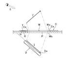
- the display device has a flat information holding body (card C or the like) disposed around an imaging optical element (micromirror array M) disposed on the upper surface of the housing.
- the identification information (IC tag T) held by the information input body) is read by the recognition means (reader R), and the information is transmitted from the recognition means to the control means of the display D, whereby the display surface Da is imaged optically.
- An image (image I) corresponding to the information holding body is displayed on the display D arranged in a state inclined at a predetermined angle ⁇ with respect to the element, and a projected image of this image is passed through the imaging optical element, It is displayed as an aerial image I ′ that appears in the space above the housing.
- symbol P in FIG. 10 shows the element surface of the micromirror array M, Ma and Mb show the upper surface and lower surface of the micromirror array M, respectively.
- the present invention has been made in view of such circumstances, and a stereoscopic two-dimensional image corresponding to an information holding body arranged around an imaging optical element is richly realistic at an appropriate timing above the apparatus. It is an object of the present invention to provide a display device that can display on the screen.
- a display device includes a housing that accommodates a display, an imaging optical element that is disposed on the top surface of the casing so as to transmit light, and a lower part of the imaging optical element.
- a display disposed with its display surface inclined at a predetermined angle with respect to the lower surface of the imaging optical element, an information holding body placed on the upper surface of the housing, and the information holding body
- a reader that reads information to be contacted, a sensor that detects the presence or absence of an object on the top surface of the housing, and a function that displays an image on the display, and controls the image based on signals from the reader and the sensor
- a display device comprising: a control means, wherein the control means is based on the information holding body information transmitted from the reader and the object detection signal transmitted from the sensor; Display status of (B) below A configuration that switches the.
- the present inventor has conducted research in order to solve the above problems, and as a result, in addition to the reader for reading the identification (individual) information of the information holding body, the information holding body is brought into contact (adherence to the upper surface). By separately providing sensors for detection and using the detection signals from these sensors in combination, it is possible to effectively provide images (still images, moving images, etc.) corresponding to this information holding body at the optimal timing for the viewer.
- the headline the present invention has been reached.
- contact between the upper surface of the housing and the information holding body means “contact” where the gap between the upper surface and the holding body is 0 (zero), and “contact” where the gap is 2 mm or less. Includes state.
- the above-mentioned “readable signal by the reader” means that the distance between the reader and the information holding body (IC tag) is within 10 cm according to the “proximity type” described in ISO / IEC 10536 related to the IC card. This refers to a state in which simple communication is possible (actually, including a distance that allows one-way communication over a longer distance).
- the display device of the present invention According to the display device of the present invention, signal information (information specific to an information holding body) obtained from a reader that reads information in a non-contact manner and signal information (information holding) obtained from a sensor that detects the presence or absence of an object on the top surface of the housing Body detection signal) to read the individual information of the information holding body close to the upper surface of the housing, and prepare the image corresponding to the information holding body, and the prepared image to the imaging optical element
- the display device of the present invention can display an effective aerial image corresponding to the information holding body at an optimal timing with a sense of realism as if the aerial image actually exists there. .
- the information holding body is a flat plate, and a light transmission part corresponding to the planar shape of the imaging optical element is provided in part of the information holding body.
- An image is formed so as to form an image through the light transmission portion.
- a flat information holding body such as a card is placed on the upper surface of the device according to the above configuration, and at the same time, the aerial image emerges from the inside of the flat information holding body (light transmitting portion) with good timing. It comes to come. Due to these synergistic effects, the display device of the present invention can make the aerial image corresponding to the flat information holding body look more impressive.
- those in which the tilt angle of the display surface of the display with respect to the lower surface of the imaging optical element is set to 30 ° or more and less than 90 ° are the three-dimensional images displayed above.
- a three-dimensional image can be displayed as a three-dimensional image with a stronger floating feeling.
- the “imaging optical element” that can be used in the display device of the present invention includes a refraction type imaging element (a variety of lenses including a Fresnel lens and the like, an afocal optical element) that forms a mirror image of a projection object as a real image. System micromirrors, corner reflectors, etc.).
- the outer shape is a panel shape or a flat plate shape, and the front and back surfaces (upper and lower surfaces) are relatively flat and flat.
- the “upper surface” and “lower surface” of the imaging optical element indicate a surface corresponding to the outer side or the inner side of the casing such as a case or a housing, and serves as a reference for imaging (refractive point of the optical path). A surface substantially parallel to the “element surface” of the imaging optical element.
- 1 is a partial cross-sectional view illustrating a basic configuration of a display device according to an embodiment of the present invention.
- 1 is an external perspective view of a display device according to a first embodiment of the present invention. It is sectional drawing which shows the structure of the display apparatus of the said 1st Embodiment. It is an external appearance perspective view of the display apparatus of 2nd Embodiment of this invention. It is a perspective view which shows one structural example of the micromirror array used for the display apparatus of this invention. It is a perspective view of the micromirror array. It is a perspective view which shows the other structural example of the micromirror array used for the display apparatus of this invention.
- FIG. 1 It is a perspective view which shows the further another structural example of the micromirror array used for the display apparatus of this invention. It is a figure explaining the structure of the modification of the micromirror array used for the display apparatus of this invention. It is a partial cross section figure explaining the structure of the conventional display apparatus.
- FIG. 1 is a diagram for explaining a basic configuration of a display device according to the present invention, which is different from the conventional example shown in FIG. 10 in that a sensor S is provided.
- a sensor S is provided in FIG. 1 in order to briefly explain only the principle of the present invention.
- members such as a case and a housing, and parts such as wiring and electrical components are not shown.
- a flat information holding body (card C in the drawing) that holds identification information is drawn with exaggerated thickness.
- the display device includes a panel-shaped micromirror array imaging optical element (hereinafter referred to as “micromirror array M”), a flat panel display (hereinafter referred to as display D), and this display. And a control means (not shown) for controlling the image (image I) displayed on D, and the lower surface Mb side of the micromirror array M by reflection of light by a number of corner reflectors provided in the micromirror array M
- the image I displayed on the display surface Da of the display D disposed in a state inclined at a predetermined angle ( ⁇ ) is a space image I ′ rising obliquely in the space on the upper surface Ma side of the micromirror array M. The image is formed so as to emerge.
- the display device has an information input surface (operation surface) on which an upper surface of the display device is placed to read the identification information held by the information holding body (card C), and the micromirror array M ,
- a reader R for reading the identification (individual) information of the card C placed in a non-contact manner, and for detecting that the information holding body such as the card C is in contact with the upper surface of the apparatus.
- a sensor S for detecting the presence or absence of an object is disposed.
- the display device places the card C on the basis of the information of the information holding body (card C) transmitted from the reader R to the control unit and the object detection signal transmitted from the sensor S to the control unit.
- the control means reads the individual information (IC tag T) of the card C close to the upper surface of the casing of the apparatus and prepares the image I corresponding to the card C on the display D, and the preparation
- the display state in which the image I is formed as a spatial image I ′ in the space above the housing via the micromirror array M is quickly switched. This is a feature of the display device of the present invention.
- the display device having the above configuration, by using the information of the information holding body (card C) transmitted from the reader R to the control unit and the object detection signal transmitted from the sensor S to the control unit,
- the reader R reads individual information held by the card C and controls it from the reader R.
- the control means can prepare in advance a video (image I) corresponding to the card C to be displayed on the display D (standby state).
- the control means immediately displays the video (image I) based on the object detection signal transmitted from the sensor S to the control means.
- the projection image of the image I is displayed on the display D, and is displayed as the aerial image I ′ on the upper side of the apparatus through the opening Ca (light transmission portion) provided in the micromirror array M and the card C (display). Status).
- the control unit reads the individual information of the card C adjacent to the upper surface of the housing of the device and prepares the display I with the image I corresponding to the card C.
- the display state in which the prepared image I is formed as an aerial image I ′ in the space above the housing via the micromirror array M can be quickly switched.
- the display of the aerial image I ′ is performed simultaneously with the placement of the card C (contact with the upper surface) based on the detection signal of the object (card C). I 'can be felt as if it came out of the inside of the card C (light transmission part) with good timing.
- the display device of the present invention can display an effective aerial image I ′ corresponding to the information holding body (such as the card C) at an optimal timing as if the aerial image I ′ actually exists. It can be displayed with a rich sense of reality.
- the imaging optical element used in this display device various lenses including a Fresnel lens and the like, and a refractive imaging element such as an afocal optical micromirror and a corner reflector can be used.
- a micromirror array M corner reflector array
- the detailed structure of the micromirror array M having a characteristic configuration will be described in detail later.
- the micromirror array M is arranged so as to be substantially horizontal with respect to the viewer's viewpoint (sense) by an arbitrary fixing member or the like.
- the flat panel display (display D) for displaying the image I is predetermined from the front side (front E side) to the back side of the viewer with respect to the lower surface Mb of the micromirror array M.
- the aerial image I ′ projected through the micromirror array M is directed toward the viewer.
- the display D used for displaying the image I a liquid crystal display panel (LCD) having a backlight, a plasma display panel, an organic EL display panel, and the like, “white” with no bias as much as possible over the entire visible light wavelength.
- a display panel that can reproduce “black” when not displayed with good contrast can be used.
- the display D may be a display unit such as a mobile phone or a portable information terminal.
- the size of the display surface Da is the size (planar shape) of the micromirror array M. The corresponding size can be used.
- the inclination angle ⁇ of the display D is set to 30 ° or more and less than 90 ° (30 ° ⁇ ⁇ ⁇ 90 °) in consideration of the posture and distance of the viewer who uses the display device.
- the flat information holding body (card C) placed on the upper side of the micromirror array M has a flat plate shape as a whole.
- a light transmission part (opening Ca) corresponding to the planar shape of the mirror array M is provided, and the spatial image I ′ is formed through the opening Ca.
- curd C is a shape close
- other polygonal shapes such as a circular shape, an elliptical shape, or a hexagonal shape may be used.
- a transparent plate made of glass or plastic may be fitted into the opening Ca.
- the card C can be a sheet or thin plate made of paper, plastic, etc. Specific examples include entertainment cards for games, message cards, educational cards, shopping cards, Examples include authentication cards, information exchange cards, books such as picture books, and albums.
- the card C has an IC tag as unique identification information (individual information) for identifying the card C at a position corresponding to the reader R of the display device (a position indicated by a symbol T in FIG. 1).
- RFID unique identification information
- two-dimensional or one-dimensional barcode (printing), and the like are arranged.
- the information held by these IC tags T and barcodes is read by the corresponding reader R, and the information is transmitted to the control means of the display D by wired or wireless communication. Is done.
- an IC tag (RFID) reader or an NCF reader including a reader / writer
- an antenna such as an HF or UHF band
- an optical sensor such as a C-MOS image sensor (camera) or an optical scanner
- the reader and information conform to the “proximity type” described in ISO / IEC 10536.
- a reader device capable of steady communication (data reading) at a distance of 10 cm or more from the holding body (IC tag T) is used.
- a sensor S for detecting that the information holding body such as the card C is in contact with the upper surface of the apparatus various electromagnetic ON-OFF switches such as a pressure sensitive switch and the distance to the card C are measured.
- An infrared sensor, an image sensor, or the like that can be used can be used. Among them, an infrared sensor that is simple in structure and stable in operation, and that can know the presence or absence of contact (existence) of the card C is preferably used.
- the sensor S can be installed anywhere on the upper surface of the apparatus or the edge of the upper surface of the apparatus as long as it can detect the contact of the information holding body such as the card C. It is desirable to arrange at a position near the array M.
- the reader R for reading the information of the card C in a non-contact manner and the sensor S for detecting the contact of the information holding body such as the card C with the upper surface of the apparatus are arranged on the viewer E side (front side).
- the installation position is not limited to this, and the reader R can communicate with an information holding body such as the card C such as the inside of the apparatus (case). Should be arranged.
- the sensor S is arranged at an appropriate position where the presence or absence of the information holding member can be easily detected in consideration of the shape of the bottom surface of the information holding body that is in contact with the upper surface of the apparatus, such as the periphery of the imaging optical element and the upper surface edge of the apparatus be able to.
- the information holding body placed on the upper surface of the apparatus is described as an example of a flat or sheet-like information such as a game card, but the information holding body may be an IC tag such as a figure or a model. It is also possible to use a three-dimensional object having individual information such as a bar code. However, in the case of these three-dimensional objects, there may be a case where an opening (light transmission part) for allowing the aerial image I ′ to pass therethrough cannot be provided. In addition, the sensor S that detects the presence or absence of the information holding body needs to be arranged in consideration of the bottom shape of the three-dimensional object and its mounting position.
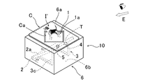
- FIG. 2 is an external perspective view of the display device according to the first embodiment of the present invention
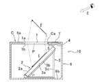
- FIG. 3 is a partial cross-sectional view showing the configuration of the display device.
- the display device 10 also includes a panel-like micromirror array imaging optical element (micromirror array 1) and a flat panel display (liquid crystal display 2), and is provided in a large number on the micromirror array 1.
- the image (image I) displayed on the liquid crystal display 2 arranged on the lower surface 1b side of the micromirror array 1 by reflection of light by the micromirror (corner reflector) is displayed in the space on the upper surface 1a side of the micromirror array 1.
- the aerial image I ′ rising obliquely the image is formed so as to rise up in the space.
- the display device 10 also has the liquid crystal display 2 on the mounting table 3 with the display surface 2a inclined at a predetermined angle ⁇ (30 ° or more and less than 90 °) with respect to the lower surface 1b of the micromirror array 1. It is placed.
- the upper surface (top plate) 6a of the case 6 is substantially flat so that a flat information holding body such as a card C can be placed thereon.
- the display device 10 is similar to the display device described in the above embodiment, on the upper surface 6a of the case 6 on which the information holding body is placed, individual information (card C) held by the flat information holding body (card C).
- An IC tag reader (reader / writer) 4 for reading the IC tag T) in a non-contact manner and an infrared sensor 5 for detecting the presence / absence (contact) of an object on the upper surface 6a are provided.
- the mounting table 3 including the mounting surface 3a for mounting the liquid crystal display 2 includes a plate-like member 3b that also serves as the above-described mounting surface 3a and bases 3c and 3c. Is disposed inside a case 6 (dark box shape). As shown in FIG. 3, the plate-like member 3 b is attached to the bases 3 c and 3 c in a state where it is inclined by a predetermined angle ⁇ with respect to the bottom surface 6 b of the case 6 and the bottom surface 1 b (or the element surface P) of the micromirror array 1.
- the upper surface of the liquid crystal display 2 serves as a mounting surface 3a.
- the display surface 2 a is inclined by ⁇ ° with respect to the element surface P of the micromirror array 1. It is supposed to be retained.
- the inclination angle ⁇ of the mounting surface 3a in the case 6 with respect to the lower surface 1b (element surface P) of the micromirror array 1 is adjusted so that the image formation by the micromirror array 1 is optimal. It is set to 30 ° or more and less than 90 °, preferably 40 ° or more and 80 ° or less.
- the casing (case 6) that accommodates the liquid crystal display 2 and the mounting table 3 has a substantially box shape (box shape), and the substantially square micromirror array 1 is fitted into an opening provided on the upper surface 6a thereof. (See FIG. 2). 2 and 3 show a state in which the same card C as that of the above embodiment is already placed on the upper surface (top plate) 6a of the case 6.
- FIG. 1 shows a state in which the same card C as that of the above embodiment is already placed on the upper surface (top plate) 6a of the case 6.
- the display device 10 is configured such that the observer E or the like approaches the IC card reader 4 while the prepared card C is brought close to the device (case 6) and placed at a predetermined position on the upper surface 6a. Based on the information on the card C transmitted from the infrared sensor 5 to the control means and the object detection signal transmitted from the infrared sensor 5 to the control means, a three-dimensional space image I ′ is displayed above the upper surface 6a. It is like that.
- the control means prepares an image I corresponding to the card C in advance (standby state). After that, when the card C is placed (contacted) on the case upper surface 6a, the control means immediately displays the image I on the liquid crystal display based on the object detection signal transmitted from the infrared sensor 5.
- the projection image of this image I is displayed as an aerial image I ′ on the upper side of the apparatus through the opening Ca (light transmission part) provided in the micromirror array 1 and the card C (display state). ). The display of the aerial image I ′ is continued while the card C is placed.
- the display device 10 is based on the object detection signal (disruption) transmitted from the infrared sensor 5 as in the above embodiment.
- the display of the image I is immediately stopped.
- the IC tag reader 4 repeatedly performs the identification information reading operation (waiting state loop) while waiting for the next card C or the like to approach (until it enters the readable area).
- the individual information held by the card C is read by the IC tag reader 4 before the card C contacts the case upper surface 6a, and the image I displayed on the liquid crystal display 2 by the control means based on the individual information is displayed.
- the image I is displayed on the liquid crystal display 2 in synchronization with the “standby state” prepared in advance and the contact of the card C, and the projected image of the image I is displayed on the upper side of the case 6 as the aerial image I ′.
- “Display state” can be switched immediately. Therefore, the display device 10 of the present embodiment can also display an effective aerial image I ′ corresponding to the information holding body (the card C or the like) with a sense of realism at an optimal timing.
- the detection sensitivity of contact (contact) by the infrared sensor 5 is set to a value slightly larger than the distance 0 (zero), specifically, a distance of 5 mm or less, a distance of 2 mm or less, or the like. Thereby, the influence of a detection time lag can be avoided.
- the backlight of the liquid crystal display 2 is set in advance at the stage of preparing the image I in advance before placing the information holding body.
- a black image is superimposed on the image I (closed by the liquid crystal shutter) and displayed, and the upper black image is removed in accordance with the detection signal of the infrared sensor 5 (liquid crystal A method of opening the shutter) may be adopted. Thereby, the influence of lighting time lag can be reduced.
- FIG. 4 is an external perspective view of the display device according to the second embodiment of the present invention.
- symbol is attached
- the IC tag reader 4 and the infrared sensor 5 are connected to a smartphone 8 described later by wireless communication such as Bluetooth (registered trademark).
- the housing 7 used in the display device 20 of the second embodiment has a shape without a lateral wall surface, and one side surface (slope 7 c) is displayed on a display (smart phone 8) described later. Is used as a mounting surface (a mounting surface inclined at a predetermined angle ⁇ ). Further, on the upper surface (top plate) 7a of the housing 7, a card C similar to that of the above embodiment is placed.
- a suction (adhesive) tape or the like for fixing the display (smartphone 8) is attached to the placement surface (slope 7c) of the display device 20, and the smartphone 8 temporarily fixed thereon is It has become removable. Therefore, as the display of the second embodiment, in addition to the smartphone 8, the display unit of the tablet PC, digital photo frame, portable game machine, portable book reader, PDA, electronic dictionary, etc. is always exposed. Among the types that are (not covered), a size that can be placed on the placement surface (slope 7c) can be used. Moreover, the housing 7 has an advantage that the smartphone 8 and the like can be easily and easily inserted, removed, and exchanged.
- the smartphone 8 or the portable information terminal or the like when used as a display, some of these devices have an IC tag reader (NFC reader / writer) or optical device unique to the device on the back surface (the back surface of the display surface 8a in the display). Some are equipped with a type sensor (CCD camera) or the like.
- the smartphone 8 includes the NFC reader / writer, the NFC reader / writer may be used for reading information from the information holding body instead of the IC tag reader 4.
- the smartphone 8 having an optical sensor such as an image sensor or a line scanner on the back side of the display surface 8a, for example, a shooting through-hole, a hole, or the like is provided on the mounting surface (slope 7c) at the corresponding position.
- the card C may be placed on the top plate (upper surface 7a) after the information such as the barcode of the information holding body is read through the through hole.
- the card C is inserted under the top plate to read (read) the identification information, and then the card C is placed on the upper surface 7a. It may be placed.
- the individual information held by the card C (flat information holder) to be placed on the upper surface 7a of the housing 7 is stored in the IC tag reader 4 or the NFC reader / phone embedded in the smartphone 8.
- the data is read by a writer or the like, and the information is transmitted to the control means of the display (smart phone 8), and the image I corresponding to the card C is prepared in advance (standby state).
- the control means immediately displays the image I on the liquid crystal display based on the object detection signal transmitted from the infrared sensor 5.
- Smart phone 8 Smart phone 8
- the projected image of this image I is displayed as an aerial image I ′ on the upper side of the apparatus through the opening Ca (light transmitting portion) provided in the micromirror array 1 and the card C.
- Display state the display state.
- the display of the aerial image I ′ is continued while the card C is placed, as in the first embodiment.
- the display device 20 determines the image I based on the change (disruption) of the object detection signal transmitted from the infrared sensor 5. Cancel the display.
- the IC tag reader 4 repeats the identification information reading operation (loop) while waiting for the next card C or the like to approach (until it enters the readable area). .
- the display device 20 of the present embodiment is also in contact with the card C and the “standby state” in which the control means prepares in advance an image I to be displayed on the display of the smartphone 8 based on the individual information held by the card C.
- the above-mentioned information is displayed at the optimum timing by switching the “display state” in which the image I is displayed on the display of the smartphone 8 at the same timing and the projected image of the image I is displayed as the aerial image I ′ on the upper side of the housing 7.
- An effective aerial image I ′ corresponding to the holding body (card C or the like) can be displayed with a rich sense of reality.
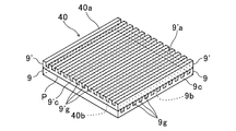
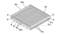
- 5 to 9 are diagrams illustrating the configuration of the micromirror array used in the above embodiment.
- the micromirror arrays shown in FIGS. 5 to 8 are a plurality of straight lines parallel to each other by dicing using a rotary blade on one surface of a transparent flat substrate.
- the two optical elements in which the groove-like grooves are formed at a predetermined interval are arranged in any one of the following modes (X) to (Z) so that the extending direction of the linear groove of each optical element is orthogonal to each other in plan view Are configured as a set in a superposed state.
- (X) A mode in which the front surfaces formed with linear grooves in each optical element are in contact with each other.
- micromirror array shown in FIG. 9 is parallel to each other by dicing using a rotary blade on each of the other surface opposite to one surface of one transparent flat substrate constituting the optical element.
- a plurality of linear grooves are formed at a predetermined interval so that the linear grooves on the front surface side and the linear grooves on the back surface side are orthogonal to each other in plan view.
- each micromirror array will be described by taking the micromirror array 30 of FIG. 6 as an example.
- the micromirror array 30 shown in FIG. 6 is configured by overlapping the optical elements (9, 9 ′) shown in FIG. Yes.
- Substrates 9 and 9 ′ (substrates before formation of grooves 9g and 9′g) constituting each optical element are bases for engraving and processing linear grooves 9g and 9′g, such as glass and acrylic resin. Further, it is made of a material having a visible light transmittance of 80% or more.
- the substrates 9 and 9 ′ are usually hard plates having a certain thickness (thickness of about 0.5 to 10.0 mm), and the upper surface (front surfaces 9a and 9′a) is diced.
- the linear grooves 9g and 9'g are formed by engraving.
- the convex portions formed by leaving the flat portions (plate portions 9c, 9'c) where the engravings of the grooves 9g, 9'g have not reached between the grooves 9g, 9'g are formed. It is a support base for the section.
- the grooves 9g and 9'g on the substrates 9 and 9 ' are formed by a rotary blade (cutting) such as a dicing machine, and are formed on the processing target surface (front surface) of the substrates 9 and 9'. These are formed at a predetermined interval (pitch) in one direction and parallel to each other. Note that the side surfaces (wall surfaces) constituting these grooves 9g, 9'g are formed by dicing using the rotary blade, and thus are formed on a light-reflective vertical surface (mirror surface).
- a rotary blade such as a dicing machine
- the grooves 9g and 9′g obtained by engraving using a dicing blade or the like are usually 0.015 mm (15 ⁇ m) to 0, although depending on the thickness of the blade (total thickness between the end surfaces of the rotary blades).
- a blade having a thickness of about 3 mm (300 ⁇ m) is used, grooves 9g and 9′g having a groove width of about 20 to 350 ⁇ m and a groove depth of about 50 to 500 ⁇ m are formed.
- the remaining region (projection strip) where 9′g is not formed is a parallel rib shape having a width (W) of about 50 to 300 ⁇ m and a height of about 50 to 500 ⁇ m (same as the depth of the groove). ing.
- the grooves 9g and 9′g of the substrate 9 and the substrate 9 ′ formed in the same shape are used. Are arranged so that their continuous directions are orthogonal to each other in plan view (three-dimensionally “twisted position”).
- the micromirror arrays 30, 40, and 50 shown in FIGS. 6 to 8 are configured as described above.
- the micromirror array 30 shown in FIG. 6 includes two optical elements (substrates 9, 9 ′), the upper substrate 9 ′ is turned upside down, and the upper substrate 9 ′ is rotated 90 ° with respect to the lower substrate 9 (the state shown in FIG. 5).
- the front surface 9′a in which the groove 9′g in the substrate 9 ′ is formed is brought into contact with the front surface 9a in which the groove 9g in the lower substrate 9 is formed.
- the substrates 9 and 9 ′ are stacked one above the other so that the extending directions of the grooves 9g and the grooves 9′g provided on the substrate are orthogonal to each other in a plan view (mode (X)) .
- the micromirror array 40 shown in FIG. 7 uses the two optical elements (substrates 9 and 9 ′) to extend the grooves 9g and the grooves 9′g provided on the substrates 9 and 9 ′.
- the groove 9g in the lower substrate 9 is formed in a state where the upper substrate 9 ′ is rotated 90 ° with respect to the lower substrate 9 so that the continuous directions are orthogonal to each other in plan view.
- the back surface 9'b (plate-like portion 9'c) in which the groove 9'g of the upper substrate 9 'is not formed is brought into contact with the front surface 9a, and the substrates 9, 9' are overlapped with each other.
- the micromirror array 40 is configured as one set [the mode (Y) described above]. Even when the grooves 9g and the grooves 9'g of the substrates 9 and 9 'are overlapped so as to face the lower side in the figure, a micromirror array having the same configuration can be obtained.
- the micromirror array 50 shown in FIG. 8 uses the two optical elements (substrates 9 and 9 ′) to invert the lower one substrate 9 ′ and turn the substrate 9 ′ to the other upper side.
- the substrate 9 rotated by 90 °
- the back surface of the upper substrate 9 (the lower surface of the plate-like portion 9c)
- the back surface of the lower substrate 9 ′ (the upper surface of the plate-like portion 9′c)
- the substrates 9 and 9 ′ are stacked one above the other so that the extending directions of the grooves 9g and the grooves 9′g provided on the substrates 9 and 9 ′ are orthogonal to each other in plan view.
- the micromirror array 50 is configured as the above-described (Z) mode.
- each of the micromirror arrays 30, 40, 50 is configured by using two substrates 9, 9 ′ each having a straight groove (g).
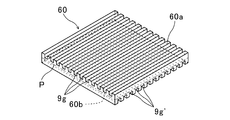
- the micromirror array 60 is composed of a single substrate (optical element). That is, as shown in FIG. 9, the micromirror array 60 has a dicing process using the rotary blade or the like on the upper front surface 60a and the lower back surface 60b of a transparent flat substrate, respectively.
- a plurality of linear grooves 9g and grooves 9g ′ parallel to each other are formed at a predetermined interval, and each groove 9g on the front surface 60a side and each groove 9g ′ on the back surface 60b side are The formation directions (continuous directions) are arranged so as to be orthogonal to each other in plan view.
- Each of the micromirror arrays 30, 40, 50, 60 has openings provided on the upper surfaces (6a, 7a) of the respective display devices as in the first embodiment of FIG. 2 and the second embodiment of FIG.
- the entire pair of light reflecting surfaces (the first mirror surface and the second mirror surface) constituting each corner reflector are directed to the viewer's viewpoint side (reference numeral E side in each figure). It is arranged in a state rotated by 45 ° with respect to the front of the viewer.
- each micromirror array 30, 40, 50, 60 light incident from one surface side (lower side) of each micromirror array is reflected once by the first mirror surface and the second mirror surface, respectively. Then, the reflected light is transmitted to the other surface side (upper side).
- each micromirror array 30, 40, 50, 60 used in the display device of each embodiment of the present invention is a display arranged on one surface side of the micromirror array as shown in FIGS.
- the mirror image (spatial image I ′) of the displayed image (image I) can be imaged at a spatial position on the other surface side that is plane-symmetric with respect to the element surface P of the micromirror array.
- this display device is suitable for use as a game machine, a portable device for education, a hanging picture book, a picture book that pops out, and the like, which children are likely to be interested in.
Landscapes
- Physics & Mathematics (AREA)
- General Physics & Mathematics (AREA)
- Optics & Photonics (AREA)
- Engineering & Computer Science (AREA)
- Multimedia (AREA)
- Signal Processing (AREA)
- Testing, Inspecting, Measuring Of Stereoscopic Televisions And Televisions (AREA)
- Controls And Circuits For Display Device (AREA)
Priority Applications (2)
| Application Number | Priority Date | Filing Date | Title |
|---|---|---|---|
| US15/120,431 US9706195B2 (en) | 2014-05-29 | 2015-04-13 | Display device |
| CN201580008870.6A CN106030379B (zh) | 2014-05-29 | 2015-04-13 | 显示装置 |
Applications Claiming Priority (2)
| Application Number | Priority Date | Filing Date | Title |
|---|---|---|---|
| JP2014-111145 | 2014-05-29 | ||
| JP2014111145A JP5947333B2 (ja) | 2014-05-29 | 2014-05-29 | 表示装置 |
Publications (1)
| Publication Number | Publication Date |
|---|---|
| WO2015182265A1 true WO2015182265A1 (ja) | 2015-12-03 |
Family
ID=54698606
Family Applications (1)
| Application Number | Title | Priority Date | Filing Date |
|---|---|---|---|
| PCT/JP2015/061330 Ceased WO2015182265A1 (ja) | 2014-05-29 | 2015-04-13 | 表示装置 |
Country Status (4)
| Country | Link |
|---|---|
| US (1) | US9706195B2 (enExample) |
| JP (1) | JP5947333B2 (enExample) |
| CN (1) | CN106030379B (enExample) |
| WO (1) | WO2015182265A1 (enExample) |
Families Citing this family (6)
| Publication number | Priority date | Publication date | Assignee | Title |
|---|---|---|---|---|
| FR3050053B1 (fr) * | 2016-04-06 | 2018-05-04 | L'air Liquide, Societe Anonyme Pour L'etude Et L'exploitation Des Procedes Georges Claude | Procede de calcul de l'autonomie d'un ensemble de distribution de gaz |
| JP6829996B2 (ja) * | 2017-01-13 | 2021-02-17 | リンナイ株式会社 | 加熱装置 |
| JP6756281B2 (ja) | 2017-03-14 | 2020-09-16 | オムロン株式会社 | 表示方法および表示装置 |
| CN107390380B (zh) * | 2017-05-12 | 2021-08-10 | 上海誉沛光电科技有限公司 | 一种显示装置、导光平板及多层悬浮显示设备 |
| TWM617658U (zh) * | 2021-03-31 | 2021-10-01 | 全台晶像股份有限公司 | 浮空影像觸控顯示裝置 |
| JP7766421B2 (ja) * | 2021-07-01 | 2025-11-10 | マクセル株式会社 | 空中浮遊映像表示装置 |
Citations (4)
| Publication number | Priority date | Publication date | Assignee | Title |
|---|---|---|---|---|
| JP2003098479A (ja) * | 2002-07-30 | 2003-04-03 | Pioneer Electronic Corp | 画像表示装置 |
| JP2014010161A (ja) * | 2012-06-27 | 2014-01-20 | Nitto Denko Corp | 表示入力装置 |
| JP2014021305A (ja) * | 2012-07-19 | 2014-02-03 | Nitto Denko Corp | 表示入力装置 |
| JP2014032600A (ja) * | 2012-08-06 | 2014-02-20 | Nitto Denko Corp | 表示入力装置 |
Family Cites Families (7)
| Publication number | Priority date | Publication date | Assignee | Title |
|---|---|---|---|---|
| WO2008041314A1 (fr) * | 2006-10-02 | 2008-04-10 | Pioneer Corporation | Dispositif d'affichage d'images |
| JP4901539B2 (ja) | 2007-03-07 | 2012-03-21 | 株式会社東芝 | 立体映像表示システム |
| JP2012078571A (ja) * | 2010-10-01 | 2012-04-19 | Pioneer Electronic Corp | 画像表示装置 |
| JP2013069272A (ja) * | 2011-09-07 | 2013-04-18 | Nitto Denko Corp | ユーザインタフェース表示装置 |
| JP2013228671A (ja) | 2012-03-30 | 2013-11-07 | Nitto Denko Corp | 表示装置 |
| JP6143161B2 (ja) | 2012-03-30 | 2017-06-07 | 日東電工株式会社 | 表示装置 |
| JP5997606B2 (ja) * | 2012-12-26 | 2016-09-28 | 日東電工株式会社 | 表示装置 |
-
2014
- 2014-05-29 JP JP2014111145A patent/JP5947333B2/ja not_active Expired - Fee Related
-
2015
- 2015-04-13 CN CN201580008870.6A patent/CN106030379B/zh not_active Expired - Fee Related
- 2015-04-13 WO PCT/JP2015/061330 patent/WO2015182265A1/ja not_active Ceased
- 2015-04-13 US US15/120,431 patent/US9706195B2/en not_active Expired - Fee Related
Patent Citations (4)
| Publication number | Priority date | Publication date | Assignee | Title |
|---|---|---|---|---|
| JP2003098479A (ja) * | 2002-07-30 | 2003-04-03 | Pioneer Electronic Corp | 画像表示装置 |
| JP2014010161A (ja) * | 2012-06-27 | 2014-01-20 | Nitto Denko Corp | 表示入力装置 |
| JP2014021305A (ja) * | 2012-07-19 | 2014-02-03 | Nitto Denko Corp | 表示入力装置 |
| JP2014032600A (ja) * | 2012-08-06 | 2014-02-20 | Nitto Denko Corp | 表示入力装置 |
Also Published As
| Publication number | Publication date |
|---|---|
| JP5947333B2 (ja) | 2016-07-06 |
| US20170013256A1 (en) | 2017-01-12 |
| CN106030379B (zh) | 2017-09-15 |
| JP2015225287A (ja) | 2015-12-14 |
| US9706195B2 (en) | 2017-07-11 |
| CN106030379A (zh) | 2016-10-12 |
Similar Documents
| Publication | Publication Date | Title |
|---|---|---|
| JP5947333B2 (ja) | 表示装置 | |
| JP5997606B2 (ja) | 表示装置 | |
| JP6143161B2 (ja) | 表示装置 | |
| US10275626B2 (en) | Sheet body, steroscopic object, and information code reading system | |
| TW201423160A (zh) | 顯示裝置 | |
| JP2015092205A (ja) | 画像投影システムおよびカード | |
| US10422993B2 (en) | Image display device and program | |
| TW201346471A (zh) | 顯示裝置 | |
| JP7251828B2 (ja) | 展示装置及び展示方法 | |
| US10356396B2 (en) | Exhibition device and video picture exhibition method | |
| WO2013146240A1 (ja) | 表示装置 | |
| JP5997605B2 (ja) | 表示装置 | |
| JP2014032600A (ja) | 表示入力装置 | |
| JP2015031808A (ja) | 映像表示装置及びプログラム | |
| JP2017067980A (ja) | 表示方法 | |
| KR101051473B1 (ko) | 렌티큘러 시트를 포함한 3d 영상표시 장치 및 그 영상표시 장치를 이용한 원형 스위치 | |
| JP6417454B2 (ja) | 映像表示装置 | |
| CN119213759A (zh) | 空间悬浮影像信息显示系统 | |
| JP6174093B2 (ja) | 映像表示装置 | |
| JP2023157919A (ja) | 映像表示装置 |
Legal Events
| Date | Code | Title | Description |
|---|---|---|---|
| 121 | Ep: the epo has been informed by wipo that ep was designated in this application |
Ref document number: 15798859 Country of ref document: EP Kind code of ref document: A1 |
|
| WWE | Wipo information: entry into national phase |
Ref document number: 15120431 Country of ref document: US |
|
| NENP | Non-entry into the national phase |
Ref country code: DE |
|
| 122 | Ep: pct application non-entry in european phase |
Ref document number: 15798859 Country of ref document: EP Kind code of ref document: A1 |