WO2015174506A1 - Mécanisme de fixation d'insert, outil de coupe rotatif, corps d'outil, élément cale, et élément de réglage - Google Patents
Mécanisme de fixation d'insert, outil de coupe rotatif, corps d'outil, élément cale, et élément de réglage Download PDFInfo
- Publication number
- WO2015174506A1 WO2015174506A1 PCT/JP2015/063956 JP2015063956W WO2015174506A1 WO 2015174506 A1 WO2015174506 A1 WO 2015174506A1 JP 2015063956 W JP2015063956 W JP 2015063956W WO 2015174506 A1 WO2015174506 A1 WO 2015174506A1
- Authority
- WO
- WIPO (PCT)
- Prior art keywords
- insert
- screw
- cutting
- insert mounting
- adjustment
- Prior art date
Links
Images


Classifications
-
- B—PERFORMING OPERATIONS; TRANSPORTING
- B23—MACHINE TOOLS; METAL-WORKING NOT OTHERWISE PROVIDED FOR
- B23C—MILLING
- B23C5/00—Milling-cutters
- B23C5/16—Milling-cutters characterised by physical features other than shape
- B23C5/20—Milling-cutters characterised by physical features other than shape with removable cutter bits or teeth or cutting inserts
- B23C5/22—Securing arrangements for bits or teeth or cutting inserts
- B23C5/24—Securing arrangements for bits or teeth or cutting inserts adjustable
- B23C5/2472—Securing arrangements for bits or teeth or cutting inserts adjustable the adjusting means being screws
-
- B—PERFORMING OPERATIONS; TRANSPORTING
- B23—MACHINE TOOLS; METAL-WORKING NOT OTHERWISE PROVIDED FOR
- B23C—MILLING
- B23C5/00—Milling-cutters
- B23C5/02—Milling-cutters characterised by the shape of the cutter
- B23C5/08—Disc-type cutters
-
- B—PERFORMING OPERATIONS; TRANSPORTING
- B23—MACHINE TOOLS; METAL-WORKING NOT OTHERWISE PROVIDED FOR
- B23C—MILLING
- B23C5/00—Milling-cutters
- B23C5/16—Milling-cutters characterised by physical features other than shape
- B23C5/20—Milling-cutters characterised by physical features other than shape with removable cutter bits or teeth or cutting inserts
- B23C5/22—Securing arrangements for bits or teeth or cutting inserts
- B23C5/2265—Securing arrangements for bits or teeth or cutting inserts by means of a wedge
- B23C5/2278—Securing arrangements for bits or teeth or cutting inserts by means of a wedge for plate-like cutting inserts fitted on an intermediate carrier, e.g. shank fixed in the cutter body
-
- B—PERFORMING OPERATIONS; TRANSPORTING
- B23—MACHINE TOOLS; METAL-WORKING NOT OTHERWISE PROVIDED FOR
- B23C—MILLING
- B23C5/00—Milling-cutters
- B23C5/16—Milling-cutters characterised by physical features other than shape
- B23C5/20—Milling-cutters characterised by physical features other than shape with removable cutter bits or teeth or cutting inserts
- B23C5/22—Securing arrangements for bits or teeth or cutting inserts
- B23C5/24—Securing arrangements for bits or teeth or cutting inserts adjustable
-
- B—PERFORMING OPERATIONS; TRANSPORTING
- B23—MACHINE TOOLS; METAL-WORKING NOT OTHERWISE PROVIDED FOR
- B23C—MILLING
- B23C2210/00—Details of milling cutters
- B23C2210/16—Fixation of inserts or cutting bits in the tool
- B23C2210/168—Seats for cutting inserts, supports for replacable cutting bits
Definitions
- the present invention relates to an insert mounting mechanism for mounting a cutting insert to a tool body and a cutting tool to which the insert mounting mechanism is adapted, and in particular, rotary cutting used for cutting metal materials by detachably mounting the cutting insert.
- the insert mounting mechanism for mounting a cutting insert to a tool body and a cutting tool to which the insert mounting mechanism is adapted, and in particular, rotary cutting used for cutting metal materials by detachably mounting the cutting insert.
- Patent Document 1 Conventional rotary cutting tools include those shown in Patent Document 1.
- the rotary cutting tool in which the cutting insert is detachably mounted described in Patent Document 1 uses a wedge member in order to mount the cutting insert in the insert mounting groove of the tool body.
- the cutting insert is disposed radially outward with respect to the rotation axis of the tool body.
- the wedge member is positioned in front of the cutting insert in the tool rotation direction.
- the cutting tool described in Patent Document 1 includes a support member for adjusting the position of the cutting edge of the cutting tool when the cutting edge of the cutting insert is reground.
- the support member is positioned on the radially inner side of the cutting insert.
- the cutting insert is mounted so as to come into contact with the contact surface facing the radially outer side of the support member.
- the support member is inserted into the groove portion in the direction of the rotation axis (that is, the direction orthogonal to the radial direction) so as to engage with the engagement portion of the groove portion of the tool body.
- the insertion position of the support member in the groove is selected so as to adjust the cutting edge to a desired position, and can be changed at a constant pitch in the radial direction.
- the radial position of the cutting edge can be adjusted at a constant pitch in the radial direction, but only the position adjustment of the cutting edge by the pitch can be performed.
- the adjusting mechanism for the position of the cutting edge of Patent Document 1 cannot adjust the position of the cutting edge with an arbitrary adjustment value.
- the present invention was created in view of such circumstances, and the object thereof is to make it easier to adjust the position of the cutting insert cutting edge with an arbitrary adjustment value while using a wedge member to attach the cutting insert to the tool body. It is in making it possible to do.
- An insert mounting mechanism for detachably mounting a cutting insert on an insert mounting portion of a tool body, An adjusting member that is arranged inside the cutting insert in the insert mounting portion and acts on the cutting insert, wherein the screw member is at least one screw hole formed in at least one of the adjusting member and the insert mounting portion
- the adjusting member is capable of moving forward and backward in the direction of the central axis of the screw member by rotating the screw member;
- a wedge member disposed with the cutting insert outside the adjustment member in the insert mounting portion, wherein the wedge member applies a pressing force to the cutting insert and an inner wall surface of the insert mounting portion by the wedge mounting member.
- a wedge member attached to exert, The wedge member is configured to be accessible to the screw member from the outside of the wedge member.
- the cutting insert can be firmly attached to the insert attachment portion by the wedge action of the wedge member, and the position of the adjustment member is adjusted by the screw member.
- the position of the cutting edge of the cutting insert can be adjusted with an arbitrary adjustment value.
- the wedge member is configured to be accessible from the outside of the wedge member, the screw member can be rotated without removing the cutting insert and the wedge member. Therefore, according to one aspect of the present invention, fine adjustment of the position of the cutting edge of the cutting insert can be more easily performed in a state where the cutting insert and the wedge member are arranged in the insert mounting portion.
- the wedge member has a groove or a through hole for accessing the screw member.
- the screw member includes two screw portions having different twist directions.
- one of the two screw portions may be screwed into a screw hole formed in the adjustment member, and the other may be screwed into a screw hole formed in the insert mounting portion.
- the adjustment member is an engagement portion engageable with an engagement portion provided in the insert mounting portion so as to guide the adjustment member to move in the direction of the central axis of the screw member.
- the engagement portion of the adjustment member has a serration shape.
- the serration shape may have a plurality of irregularities.
- the engaging portion may have various engaging shapes having at least one convex portion or concave portion.
- the insert mounting mechanism further includes a locator arranged in the insert mounting portion.
- the engaging portion of the insert mounting portion may be formed on the locator.
- the insert mounting mechanism further includes a second adjustment member for moving the cutting insert in a second direction that intersects (for example, substantially orthogonal to) the movement direction of the adjustment member as the screw member rotates.
- the second adjustment member may include a second screw member that can advance and retreat in the second direction.
- the present invention also resides in a tool body including the insert mounting portion of the insert mounting mechanism.
- the present invention also exists in the wedge member of the insert mounting mechanism.
- the present invention also exists in the adjustment member of the insert mounting mechanism.
- the present invention also relates to a cutting tool in which a cutting insert is detachably attached to a tool body, and the cutting tool to which the insert mounting mechanism is adapted.
- the cutting tool may be a rotary cutting tool that is rotated around a rotation axis.
- the insert mounting mechanism includes the second adjustment member
- the second direction of the second screw member may be a direction substantially parallel to the rotation axis of the rotary cutting tool.
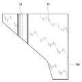
- FIG. 1 is a perspective view of a cutting tool according to an embodiment of the present invention.
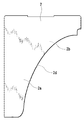
- FIG. 2 is an enlarged view of a region II of FIG. 1 in the cutting tool of FIG.
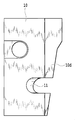
- FIG. 3 is an enlarged view of a region III of FIG. 17 in the cutting tool of FIG. 4 is a perspective view of a cutting insert in the cutting tool of FIG.
- FIG. 5 is a plan view of the cutting insert of FIG. 6 is a perspective view of a wedge member in the cutting tool of FIG.
- FIG. 7 is a plan view of the wedge member of FIG.
- FIG. 8 is a front view of the wedge member of FIG.
- FIG. 9 is a right side view of the wedge member of FIG.
- FIG. 10 is a left side view of the wedge member of FIG. FIG.
- FIG. 11 is a rear view of the wedge member of FIG. 12 is a bottom view of the wedge member of FIG.
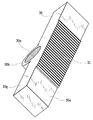
- FIG. 13 is a perspective view of an adjustment member in the cutting tool of FIG.
- FIG. 14 is a plan view of the adjustment member of FIG.
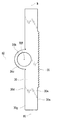
- FIG. 15 is a perspective view of a locator in the cutting tool of FIG.
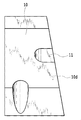
- FIG. 16 is a perspective view of the second adjustment member from which the screw member is removed in the cutting tool of FIG. 1.
- FIG. 20A is a partial schematic cross-sectional view taken along the line XXA-XXA of FIG. 3 in the cutting tool of FIG. 20B is a schematic cross-sectional view showing a state in which the position of the cutting insert is shifted from the state of FIG. 20A.
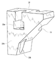
- FIG. 21 is a perspective view of the tool body of the cutting tool of FIG.
- a cutting tool 1 according to an embodiment of the present invention will be described with reference to the drawings.
- the rotary cutting tool 1 of this embodiment is a side cutter provided with a substantially disk-shaped tool body 3, and more specifically a gear cutting cutter.
- the tool body 3 has a substantially disk shape, and has two end faces 3a and 3b facing each other, and an outer peripheral portion 3c extending between the two end faces.
- a through hole 3d is formed in the tool body 3 so as to penetrate the two end faces 3a, 3b.
- the tool body 3 is attached to the main shaft or the like of the arbor or the machine tool by fitting a shaft portion (not shown) provided on the main shaft or the like of the machine tool or the like into the through hole 3d.
- the rotary cutting tool 1 including the tool body 3 is rotated with the central axis A of the through hole 3d as the rotation axis.
- a plurality of insert mounting portions 21 are formed on the outer peripheral portion 3c.
- the cutting insert 2 is attached to each insert attachment portion 21.
- the cutting insert 2 is shown in FIGS. 4 and 5 and has a plate shape, and includes two opposing end surfaces 2a and 2b and a peripheral side surface 2c extending between the two end surfaces.
- the cutting insert 2 includes a cutting edge 2d extending at the intersection of one end surface 2a and the peripheral side surface 2d.
- the cutting edge 2d is formed so that a groove whose cross-sectional shape is curved can be cut.
- the cutting edge 2d has a tooth profile curve shape (for example, an involute curve shape). Therefore, the cutting tool 1 to which the cutting insert 2 is attached is a so-called general tool, as is apparent from the above description.
- the cutting insert 2 includes a right-handed cutting insert 2 and a left-handed cutting insert 2.
- the right-handed cutting inserts 2 and the left-handed cutting inserts 2 are alternately arranged in a staggered manner on the outer peripheral portion 3 c of the tool body 3.
- a total of twelve cutting inserts 2 are arranged on the tool body 3, six on each side with respect to the end faces 3 a and 3 b of the tool body 3. Therefore, the cutting insert 2 positioned on one end surface 3a side of the two end surfaces 3a and 3b is a right-handed cutting insert, and the cutting insert 2 positioned on the other end surface 3b side is a left-handed cutting insert.
- Shown in FIGS. 4 and 5 is a right-handed cutting insert 2.
- the left-handed cutting insert 2 is mirror-symmetrical with the right-handed cutting insert 2 and will not be described.
- the curved ridge formed at the lower right of the cutting insert 2 is the cutting edge 2d.
- the end surface 2a on which the cutting edge 2d is formed at the edge is a rake surface, and is particularly referred to herein as the upper surface.
- a side surface (the curved side surface 2e in this case) of the peripheral side surface 2c where the cutting edge 2d is formed at the edge serves as a flank.
- the cutting edge 2d may extend to a portion other than the curved ridge line portion, and therefore the portion of the peripheral side surface 2c other than the curved side surface 2e may be a flank.
- the shape of the cutting edge and the number and arrangement of the cutting inserts 2 attached to the tool body are not limited to this embodiment, and may be appropriately adjusted according to the shape of the workpiece and cutting conditions.
- the cutting tool 1 has an insert mounting mechanism 100 (that is, the insert mounting mechanism 100 is adapted) for fixing or mounting (that is, mounting) the cutting insert 2 to the tool body 3.
- the insert attachment mechanism 100 includes a wedge member 10, an adjustment member 30, a locator (position adjustment member) 50, and a second adjustment member 60, which are detachably attached to the insert attachment portion 21.
- the cutting tool 1 is shown such that the central axis A (not shown in FIG. 17) of the through hole 3 d as the rotation axis of the rotary cutting tool 1 is parallel to the paper surface.
- the cross-sectional view of FIG. 18 and the cross-sectional view of FIG. 19 are partial cross-sectional views of the rotary cutting tool 1 on a plane orthogonal to the central axis A, respectively.
- 20A and 20B are schematic partial sectional views of the rotary cutting tool 1 on a plane parallel to the central axis A, respectively.
- the insert mounting mechanism 100 will be described in detail based on these assembly drawings and sectional views. First, the insert mounting portion 21 of the tool body 3 to which the insert mounting mechanism 100 is adapted will be described.
- the tool body 3 includes a plurality of support wall portions 3e on the outer peripheral portion (or outer peripheral surface) 3c. Each support wall 3e extends so as to protrude in the radial direction with respect to the central axis A.
- the support wall portions 3e are arranged at equal intervals in the circumferential direction around the central axis A of the through hole 3d.
- the number of support wall portions 3 e matches the number of cutting inserts 2 attached to the tool body 3. Therefore, here, the tool body 3 has twelve support wall portions 3e. However, the number of the supporting wall portions 3 e may not match the number of cutting inserts 2 attached to the tool body 3.
- the insert mounting portion 21 is formed between the two support wall portions 3e adjacent to each other in the circumferential direction. That is, the insert mounting portion 21 focuses on two adjacent support wall portions 30e, and when one of them is a first support wall portion 3e1 and the other is a second support wall portion 3e2 (the lower support wall portion in FIG. 21).
- the rear wall surface 3h facing the rear in the rotation direction of the first support wall portion 3e1 on the front side in the rotation direction R around the central axis A, and the second support wall portion on the rear side in the rotation direction R around the center axis A 3e2 is substantially partitioned by a front wall surface 3i facing forward in the rotational direction and a bottom wall surface 3j extending between the wall surfaces 3h and 3i.
- the insert mounting portion 21 having the three wall surfaces 3h, 3i, and 3j as the inner wall surface has a groove shape or a pocket shape, and may be hereinafter referred to as a pocket.
- the pocket 21 is formed so that the spatial region expands toward the outer side in the radial direction. This is mainly because the insert attachment mechanism 100 employs the wedge member 10 in order to firmly attach the cutting insert 2.
- each insert attaching part 21 is open in the center axis line A direction, you may have one or more wall surfaces for supporting the cutting insert 2 in the center axis line A direction.
- the pocket 21 to which the right-handed cutting insert 2 is attached is the same as the pocket 21 to which the left-handed cutting insert 2 is attached (virtual plane (not shown) orthogonal to the central axis A of the through hole 3d and passing through the outer peripheral portion 3c. )) And has a generally symmetrical relationship.
- Each pocket 21 includes a step 3 f based on the positional relationship between the wedge member 10 and the adjustment member 30, which will be described in detail later, and a recess 3 g formed in the step 3 s so as to conform to the shape of the adjustment member 30. And a plurality of screw holes for engaging with a screw member to be described later.
- the step portion 3f is formed to extend in the direction of the central axis A in the intersecting region between the rear wall surface 3h and the bottom wall surface 3j.
- the recess 3g is formed so as to cut out the step 3f toward the bottom wall surface 3j.
- the step 3f and the recess 3g are provided with respect to the rear wall 3h of the first support wall 3e1 on the front side in the rotation direction R around the central axis A among the first and second support walls.
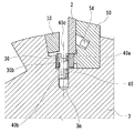
- the cutting insert 2 of the rotary cutting tool 1 is attached using a wedge member 10.
- the wedge member 10 is shown in FIGS. 6 to 12 and is designed to fix the cutting insert 2 in the pocket 21 with a wedge action.
- the wedge member 10 is fixed or attached to the pocket 21 using a wedge attachment member 20.
- the wedge mounting member 20 is a fastening screw.
- the wedge member 10 is disposed in the pocket 21.
- a screw hole 3 k is provided in the pocket 21.
- the screw hole 3k is provided in the step portion 3f and extends in a direction intersecting the bottom wall surface 3j (see FIG. 21).
- the tightening screw 20 is screwed into the screw hole 3k, and can advance and retreat in the direction of the central axis in the pocket 21 with the rotation around the central axis.
- the wedge member 10 is pushed into the back side or inside of the pocket 21 by tightening the fastening screw 20 so as to move toward the back side or radially inward of the pocket 21.
- the wedge member 10 is pushed between the rear wall surface 3h of the pocket 21 and the upper surface 2a of the cutting insert 2 as a contact surface facing the front side in the tool rotation direction R, and exerts a pressing force on them.
- the cutting insert 2 is firmly fixed to the tool body 3.
- the forward / backward direction of the wedge member 10 is a direction substantially parallel to the forward / backward direction of the fastening screw 20.
- the advancing / retreating direction of the fastening screw 20 is a direction inclined with respect to the upper surface 2 a of the cutting insert 2.
- the inclination direction of the fastening screw 20 (that is, the inclination direction of the central axis of the screw hole 3k) is determined so as to be farther from the upper surface 2a of the cutting insert 2 as the fastening screw 20 is retracted radially outward. It is determined along a virtual plane (FIG. 19) orthogonal to A.
- a virtual plane (FIG. 19) orthogonal to A.
- FIG. 13 and FIG. 14 show the adjustment member 30.
- the adjusting member 30 is a member that contacts (acts on) the cutting insert 2 and adjusts the position of the cutting edge of the cutting insert 2.
- the adjustment member 30 includes a substantially rectangular parallelepiped body portion 30a, a screw hole portion 30b provided at a substantially central position in the longitudinal direction of the body portion, and an engagement portion having a positional relationship facing the screw hole portion 30b. Serration 31 is provided.
- the main body 30a has four surfaces each extending in the longitudinal direction and two relatively small surfaces extending between the four surfaces.
- a screw hole 30b and a serration 31 are formed on two opposing surfaces of the four longitudinal surfaces of the main body 30a.
- the serration 31 is formed on a surface 30e facing the surface 30d formed so that the screw hole 30b protrudes.
- a first virtual plane S1 extending in the longitudinal direction of the main body 30a and dividing the main body 30a into approximately two equal parts is defined as shown in FIG.
- the first virtual surface S1 extends substantially parallel to the two surfaces 30d and 30e.
- the screw hole portion 30b is formed on one side (the surface 30d side) of the first virtual surface S1 so as to protrude from the main body portion 30a, and is located on the substantially opposite side to the serration 31 with respect to the first virtual surface S1.
- the second virtual surface S2 defines the central axis 30f of the screw hole 30c of the screw hole 30b. Extend to include. Surfaces other than the two opposing surfaces of the surface 30e on which the serration 31 is formed and the surface 30d formed so that the screw hole portion 30b protrudes are configured as flat surfaces. In particular, in FIG.
- a surface 30 g that is parallel to the paper surface is configured as a contact surface with the cutting insert 2 of the adjustment member 30 and is a flat surface, but may not be a flat surface.
- the protruding shape of the screw hole portion 30b from the main body portion 30a is designed so that the screw hole portion 30b fits into the recess 3g of the pocket 21.
- the serration 31 has a plurality of irregularities, and more specifically has a serration shape (sawtooth shape).
- the serration 31 may have only one convex portion or only one concave portion, but has a plurality of irregularities.
- the concave portion (valley groove) and the convex portion (mountain portion) of the serration 31 extend substantially parallel to the second virtual plane S2, and extend substantially parallel to the central axis 30f of the screw hole 30c.
- the convex portion or concave portion of the serration 31 determines the advancing / retreating direction of the adjusting member 30 in the pocket 21. Therefore, the serration 31 engages with a serration as an engaging portion of the locator 50 described later, and functions as a guide portion of the adjustment member 30.
- the serration 31 may have any shape as long as the adjustment member 30 can be prevented from tilting in the pocket 21 (that is, as long as the adjustment member 30 can be firmly guided).
- the screw member 40 is screwed into the screw hole 30c of the adjustment member 30.
- the screw hole 30c has a screw thread on its inner surface.
- the screw member 40 also contacts the pocket 21.
- the screw member 40 is formed so as to be screwed into the screw hole 3 m formed in the pocket 21.
- the screw hole 3m is positioned in the recess 3g and extends so as to intersect with the bottom wall surface 3j, in particular, at a right angle here.
- the adjustment member 30 can be moved back and forth with respect to the pocket 21 in the central axis direction of the screw member 40 (that is, the central axis direction of the screw hole 3m).
- the screw member 40 of the rotary cutting tool 1 includes two screw portions 40a and 40b having different twist directions, and is configured as a so-called left and right screw. As apparent from FIG. 18, the two screw portions of the screw member 40 are arranged side by side in the direction of the axis 40 c of the screw member 40, and one screw portion 40 a of the two screw portions is a screw hole of the adjustment member 30. The other screw portion 40 b is screwed into the screw hole 3 m of the pocket 21. Since the twist directions of the two screw portions of the screw member 40 are different from each other, the adjustment member 30 is rotated by rotating the screw member 40 engaged with the adjustment member 30 and the pocket 21 around the central axis 40c.
- the central axis 40c of the screw member 40 (that is, the central axis of the screw hole 3m) is parallel to the paper surface in FIG. 18, here, the forward and backward movement of the screw member 40 due to the engagement with the screw hole 3m is the center of the through hole 3d. It occurs along a virtual plane orthogonal to the axis A.
- the screw member 40 can freely set its forward / backward movement amount with respect to the rotation angle of the screw around the central axis 40c, and can be relatively large, for example, so that one end of the screw member 40 (a screw portion in the direction of the central axis 40c Even when the space for turning the wrench that engages with the engaging portion on the 40a side) is narrow, the position adjustment of the adjusting member 30 is easy.
- the total length (length along the first imaginary plane) of the adjusting member 30 of the rotary cutting tool 1 is about 70 mm.
- the thickness of the adjusting member 30 (the maximum length at the screw hole 30 along the second virtual surface) is about 15 mm.
- the size of the adjustment member 30 is not limited to this.
- the wedge member 10 has a wedge shape as a whole, and has a substantially hexahedral outer shape.
- the wedge member 10 further includes a screw engaging portion 10 a for attaching the wedge member and a groove 11.
- the wedge member 10 abuts against the front abutting surface 10c that can abut against the rear wall surface 3h of the support wall 3e that defines the pocket 21, and the upper surface 2a of the cutting insert 2 so as to face the front abutting surface 10c.
- a rear contact surface 10d capable of contacting.
- the groove 11 is provided in the rear contact surface 10c.
- the screw engaging portion 10a is positioned closer to the front abutting surface 10c with respect to the groove 11, and in particular is formed so as to open to the front abutting surface 10c here.
- the front contact surface 10c and the rear contact surface 10d of the wedge member 10 are formed in a wedge shape in order to firmly fix the cutting insert in the tool rotation direction R in the pocket 21, and are not parallel to each other. Yes. Further, as shown in FIG. 3, the front contact surface 10c and the rear contact surface 10d of the wedge member 10 are tapered toward the cutting edge 2d side in the central axis A direction when arranged in the pocket 21. Tilt relative to each other. Therefore, the wedge member 10 is prevented from shifting in the pocket 21 toward the cutting edge 2d.
- the screw engaging portion 10 a is engaged with the head portion 20 a of the fastening screw 20 that is a wedge mounting member, and the screw portion 20 b of the fastening screw 20 is engaged with the wedge member 10. It is configured to protrude outward.
- the fastening screw 20 is screwed into the screw hole 3k of the pocket 21 (see FIG. 19).
- Access to the fastening screw 20 of the screw engaging portion 10a is performed by inserting a wrench or a driver through an access hole 10b formed in the wedge member 10.
- the wrench or driver engages with the engaging recess of the head 20 a of the tightening screw 20.
- the access hole 10b has such a size that the head 20a of the fastening screw 20 cannot pass through.
- the groove 11 of the wedge member 10 is a groove for passing a wrench or driver for turning the screw member 40 for the adjustment member 30. Therefore, as will be described later, when the adjustment member 30 is arranged on the inner side (or the inner side) of the pocket 21 and the wedge member 10 is arranged on the outer side in the radial direction, the groove 11 is formed on the rotational axis ( It extends on an extension of the central axis 40c) and provides a working space.
- the groove 11 is formed to have a size that allows a wrench or a driver to enter and exit.
- the groove 11 may be a through hole.
- the wedge member 10 may be divided into a plurality of parts. In the case where the wedge member 10 is composed of a plurality of members, it is only necessary to ensure a working space for the screw member 40 on the extension line of the rotating shaft of the screw member 40 without covering or closing the constituent member of the wedge member 10.
- the number of wedge attachment members 20 is also plural. However, it is not limited to this. As long as a plurality of constituent members of the wedge member 10 can be integrally attached, the wedge attachment member 20 may be a single member. That is, the wedge mounting member 20 can be configured with a smaller number of members than the number of parts of the wedge member 10.
- the width of the groove 11 of the rotary cutting tool 1 is about 8 mm. However, it is not limited to this.
- the wedge member 10 may have any shape or divided shape as long as the wedge member 10 exhibits a wedge action and a wrench or a driver for turning the screw member 40 passes through the wedge member 10 so that it can work. Absent.
- a locator 50 shown in FIG. 15 is attached to the pocket 21 of the tool body 3 of the rotary cutting tool 1.
- the locator 50 is disposed on the rear side of the cutting insert 2 in the tool rotation direction R (that is, circumferential direction) of the tool body 3, and is disposed between the front wall surface 3 i that defines the pocket 21 and the lower surface 2 b of the cutting insert 2. Is done.
- the locator 50 includes screw engaging portions (abutment portions) 50a and 50b for attaching the locator 50 to the pocket 21 using screws, and screw holes 50c and 50d for attaching a second adjusting member 60 described later. Is provided.
- screw members 53 and 54 engage with the screw engaging portions 50a and 50b, respectively.
- the locator 50 is plate-shaped and includes two opposing end surfaces 50e and 50f and a peripheral side surface 50g extending therebetween.
- the locator 50 has a shape similar to the shape of the cutting insert 2.
- the locator 50 has a cutting edge 2 d of the cutting insert 2 radially outward of the tool body 3 and outward of the locator 50 by a predetermined amount in the rotation axis A direction. It is designed to substantially define the initial setting position of the cutting insert 2 so as to protrude.
- One end surface 50e of the two end surfaces of the locator 50 is configured as a contact surface that contacts the lower surface 2b of the cutting insert 2 (opposite the upper surface 2a as a rake surface).
- the locator 50 includes a serration 51 corresponding to the serration 31 of the adjustment member 30 on the end surface 50e.
- the serration 51 is formed in a serration shape so as to engage with the serration 31 of the adjustment member 30 and constitutes an engaging portion.
- the serration 51 can be configured as various concave portions or convex portions, or a composite thereof, but preferably has a serrated shape. However, the serration 51 is not limited to this.
- the serration 51 of the locator 50 may correspond to the serration 31 of the adjustment member 30 and may have any shape as long as it can determine the advance / retreat direction of the adjustment member 30 and prevent the adjustment member 30 from tilting.
- the end surface 50 f of the locator 50 is configured as a contact surface that contacts the front wall surface 3 i of the pocket 21.
- the screw engaging portions 50a and 50b are formed as stepped holes that penetrate the two end faces 50e and 50f, respectively.
- the screw holes 50c and 50d are formed on the peripheral side surface 50g and extend substantially parallel to the two end surfaces 50e and 50f that are parallel to each other.
- the serration 51 is formed in the protrusion part currently formed so that it may protrude outside from the end surface 50e in the opposing direction of the end surfaces 50e and 50f as a whole. As shown in FIG. 19, in the pocket 21, the cutting insert 2 can be placed on the protruding portion of the locator 50 and the adjustment member 30, here mainly on the adjustment member 30.
- the locator 50 is attached to the tool body 3 by screwing the screw members 53 and 54 into the screw holes of the pocket 21 through the holes of the locator 50, and a part of the tool body 3.
- the locator 50 may not be used, and the cutting insert 2 and the adjustment member 30 may be in direct contact with the front wall surface 3 i of the tool body 3.
- the engaging portions 50a and 50b of the locator 50 are not limited to being stepped through holes, and various known shapes such as grooves or recesses can be applied.
- the insert mounting mechanism 100 further includes a second adjustment member 60.
- the second adjustment member 60 includes a main body portion 60d having a flat plate shape.
- the second adjustment member 60 further includes an adjustment screw 61 for adjusting the position of the cutting edge 2d. Therefore, the main body portion 60d includes a screw hole 60a into which the adjustment screw 61 is screwed. The position of the cutting edge 2d can be adjusted by bringing the adjusting screw 61 into contact with the cutting insert 1 as necessary.
- the second adjustment member 60 is attached so that the center axis of the adjustment screw 61 that is the second screw member is substantially parallel to the center axis A, and the adjustment screw 61 can act on the cutting insert 2.
- the main body portion 60d of the second adjustment member 60 is tightened by screwing a mounting screw (see FIG. 1) into the screw holes 50c, 50d of the locator 50 attached to the tool body 3, thereby tightening the tool body 3 (here Then, it is attached to the locator 50). Therefore, the second adjustment member 60 includes engagement portions (abutment portions) 60b and 60c for attachment by attachment screws in the main body portion 60d.
- the engaging portions 60b and 60c of the second adjustment member 60 are stepped through holes, like the engaging portions 50a and 50b of the locator 50, but various known shapes such as grooves or recesses can be applied.
- the method for adjusting the position of the cutting edge by the second adjusting member 60 is not limited to the method using the adjusting screw 61. However, the adjustment method using the adjustment screw as in this embodiment is preferable because it is a simple method as will be described later. In FIG. 16, a screw thread is formed on the inner surface of the screw hole 60 a of the second adjustment member 60.
- the material around the cutting edge 2d of the cutting insert 2 is a hard material such as cemented carbide, cermet, ceramic, cubic boron nitride or the like, a surface of these hard materials coated with a PVD or CVD coating film, or a diamond It is good to be chosen from. Further, it is preferable that the material other than the cutting edge is the same hard material.
- the locator 50 is attached to the pocket 21. It should be noted that the second adjusting member 60 may be attached to the locator 50 at this time. Then, the adjustment member 30 is positioned. The adjusting member 30 is arranged such that the screw hole 30b is positioned in the recess 3g of the pocket 21 and the serration 31 engages with the serration 51 of the locator 50. Thereby, the adjustment member 30 can substantially move only in a predetermined direction (direction of the central axis 40c of the screw member 40) of the tool body 3 according to the engagement with the serrations 31 and 51, for example, the pocket 21 can contact the bottom wall surface 3j.
- the screw member 40 When the adjustment member 30 is disposed, the screw member 40 has the above-described configuration, and thus is screwed into the screw hole 30 c of the adjustment member 30 and the screw hole 3 m of the pocket 21. And the wedge member 10 is arrange
- the cutting insert 2 is arranged on the radially outer side of the main body 30a of the adjusting member 30 of the pocket 21 (that is, on the outer side of the main body 30a in the radial direction of the tool body 3) so that the upper surface 2a faces the tool rotation direction R. Is done.
- the cutting insert 2 is inserted into the space behind the wedge member 10 in the tool rotation direction and before the locator 50 in the tool rotation direction until it comes into contact with the adjustment member 30.
- the wedge member 10 may be arrange
- the cutting insert 2 can be firmly attached to the pocket 21 by the wedge action of the wedge member 10 by firmly tightening the fastening screw 20 in a state where various members are arranged around the cutting insert 2.
- the clamping screw 20 is tightened while pressing the cutting insert 10 against the locator 50, the adjusting member 30, and the second adjusting member 60, and therefore the position of the cutting edge 2d is the relative position thereof. It depends on the relationship.
- the wedge member 10 is loosened in the groove 11 of the wedge member 10. Then, a wrench or driver is inserted toward the screw member 40. Then, by rotating the screw member 40 so as to move the adjustment member 30 radially outward, the cutting member 2 is moved radially outward by the adjustment member 30 and the position of the cutting edge 2d of the cutting insert 2 is changed. Can do.
- the cutting insert 2 moves inward in the radial direction following the movement of the adjustment member 30, and the cutting edge 2d of the cutting insert 2 is moved.
- the position of can be changed.
- the wedge member 10 is firmly fixed to the pocket 21, whereby the attachment of the cutting insert 2 is completed.
- the position of the cutting edge 2d of the cutting insert 2 can be easily adjusted in the state where the wedge member 10 and the cutting insert 2 are arranged.
- the adjusting screw 61 of the second adjusting member 60 is rotated by, for example, a screwdriver while the wedge member 10 is loosened. It is done.
- the adjustment screw 61 is rotated around the central axis so as to be further screwed into the screw hole 60a.
- the cutting insert 2 is moved as indicated by the arrows. 20A, the cutting insert 2 is in contact with the main body portion 60d of the second adjustment member 60.
- the cutting insert 2 is in contact with the adjustment screw 61, but the second adjustment member. It can be easily understood from the fact that it is away from the main body 60d of 60. 20A and 20B, exactly, as in FIGS. 18 and 19, the adjustment member 30 is separated from the bottom wall surface 3j of the tool body 3. However, the movement of the adjustment screw 61 and the effect of the adjustment screw 61 are not shown. The adjustment member 30 is brought into contact with the bottom wall surface 31 so as to facilitate understanding.
- the screw member 40 for attaching and moving the adjusting member 30 can be accessed from the outside in the radial direction of the wedge member 10 with the wedge member 10 disposed. . Therefore, in the state where the wedge member 10 and the cutting insert 2 are arranged, the position of the adjusting member 30 (particularly the radial position) can be adjusted, and the position of the cutting edge 2d of the cutting insert 2 can be adjusted easily and quickly. Furthermore, since the position adjustment of the cutting edge 2d is performed by operating the screw member 40, the position adjustment amount of the cutting edge can be arbitrarily set. Therefore, the position of the cutting edge can be adjusted more suitably when the cutting edge is polished.
- the second adjustment is performed in the adjustment direction (that is, the adjustment direction in the direction of the central axis A) that intersects the adjustment direction of the position of the cutting edge by the adjustment member 30 (that is, the adjustment direction in the radial direction).
- the position of the cutting edge 2d can be adjusted. Since the position adjustment of the cutting edge by the adjustment screw 61 of the second adjustment member 60 is also the position adjustment by the screw mechanism, the position adjustment amount of the cutting edge can be arbitrarily set. Since the position of the cutting edge can be adjusted in two directions substantially orthogonal to each other (that is, in the radial direction and the axial direction), the cutting edge can be positioned more accurately.
- the insert mounting mechanism may be changed so that the adjustment direction of the position of the cutting edge by the adjustment member 30 intersects the direction of adjustment of the position of the cutting edge by the second adjustment member 60 but is not orthogonal.
- the present invention is not limited to the embodiment described above, and includes various other embodiments. Various modifications and additions can be made to the above embodiment without departing from the scope of the present invention.
- the shape of the groove processed by the cutting tool according to the present invention is not limited to the gear tooth shape.
- the present invention is not limited to the side cutter, and the present invention can also be applied to a rotary cutting tool that uses a wedge member for attaching a cutting insert, such as a face mill.
Landscapes
- Engineering & Computer Science (AREA)
- Mechanical Engineering (AREA)
- Milling Processes (AREA)
- Details Of Cutting Devices (AREA)
Abstract
Priority Applications (4)
| Application Number | Priority Date | Filing Date | Title |
|---|---|---|---|
| CN201580003183.5A CN105813787B (zh) | 2014-05-15 | 2015-05-14 | 刀片安装机构、旋转切削工具、工具主体、楔子部件及调整部件 |
| EP15792716.1A EP3069809B1 (fr) | 2014-05-15 | 2015-05-14 | Mécanisme de fixation d'insert et outil de coupe |
| US15/303,248 US10220454B2 (en) | 2014-05-15 | 2015-05-14 | Insert attachment mechanism, rotary cutting tool, tool body, wedge member and adjustment member |
| JP2015543206A JP5958785B2 (ja) | 2014-05-15 | 2015-05-14 | インサート取付機構、回転切削工具、工具ボデー、くさび部材および調整部材 |
Applications Claiming Priority (2)
| Application Number | Priority Date | Filing Date | Title |
|---|---|---|---|
| JP2014-101720 | 2014-05-15 | ||
| JP2014101720 | 2014-05-15 |
Publications (1)
| Publication Number | Publication Date |
|---|---|
| WO2015174506A1 true WO2015174506A1 (fr) | 2015-11-19 |
Family
ID=54480042
Family Applications (1)
| Application Number | Title | Priority Date | Filing Date |
|---|---|---|---|
| PCT/JP2015/063956 WO2015174506A1 (fr) | 2014-05-15 | 2015-05-14 | Mécanisme de fixation d'insert, outil de coupe rotatif, corps d'outil, élément cale, et élément de réglage |
Country Status (5)
| Country | Link |
|---|---|
| US (1) | US10220454B2 (fr) |
| EP (1) | EP3069809B1 (fr) |
| JP (1) | JP5958785B2 (fr) |
| CN (1) | CN105813787B (fr) |
| WO (1) | WO2015174506A1 (fr) |
Families Citing this family (3)
| Publication number | Priority date | Publication date | Assignee | Title |
|---|---|---|---|---|
| CN105517744B (zh) * | 2013-09-04 | 2018-06-12 | 格里森工场 | 使用棒形刀片的周缘切削刀具 |
| DE102015115310A1 (de) * | 2015-09-10 | 2017-03-16 | Hartmetall-Werkzeugfabrik Paul Horn Gmbh | Wirbelwerkzeug |
| TWI751814B (zh) * | 2020-09-22 | 2022-01-01 | 家登精密工業股份有限公司 | 支撐片狀物的中央支撐裝置及存放片狀物的儲存設備 |
Citations (5)
| Publication number | Priority date | Publication date | Assignee | Title |
|---|---|---|---|---|
| JPS56157906A (en) * | 1980-04-07 | 1981-12-05 | Gen Electric | Inserting body sheet-wedge assembled body for boring cutter which can be divided |
| JPH04112728U (ja) * | 1991-03-22 | 1992-09-30 | 三菱マテリアル株式会社 | スローアウエイ式カツター |
| JP2005103708A (ja) * | 2003-09-30 | 2005-04-21 | Sumitomo Electric Hardmetal Corp | 刃振れ調整機構付き回転切削工具 |
| US20050260045A1 (en) * | 2002-07-26 | 2005-11-24 | Dieter Raab | Cutting tool for metal removal |
| US7300231B1 (en) * | 2006-12-04 | 2007-11-27 | Hsing Chao Liu | Cutting tool carrying device for machine tool |
Family Cites Families (22)
| Publication number | Priority date | Publication date | Assignee | Title |
|---|---|---|---|---|
| US1733657A (en) * | 1927-02-04 | 1929-10-29 | Ingersoll Milling Machine Co | Cutter |
| US1865617A (en) * | 1931-05-21 | 1932-07-05 | Kearney & Trecker Corp | Metal cutting tool |
| US2652749A (en) * | 1951-10-17 | 1953-09-22 | Hagmeister Heinrich | Toolholder |
| US3079671A (en) * | 1958-10-30 | 1963-03-05 | O K Tool Co Inc | Adjustable bit holding means |
| US3217384A (en) * | 1962-02-26 | 1965-11-16 | Sandvikens Jernverks Ab | Milling cutter |
| SE318162B (fr) * | 1964-06-08 | 1969-12-01 | Fagersta Bruks Ab | |
| GB1175885A (en) * | 1967-05-01 | 1970-01-01 | Murex Ltd | Improvements in or relating to Cutting Tools |
| US3894340A (en) * | 1972-08-30 | 1975-07-15 | Jr Russell Lee Ellis | Blade setter for planers and the like |
| CA1126496A (fr) * | 1979-11-14 | 1982-06-29 | Ernest Lacasse | Outil de coupe |
| US4311418A (en) | 1980-06-24 | 1982-01-19 | General Electric Company | Adjustable axial and radial locating wedge assemblies for an indexable insert cutting tool |
| DE3708034A1 (de) * | 1987-03-12 | 1988-09-22 | Zerspanungstech Gmbh & Co Kg | Messerkopf |
| US5209610A (en) | 1991-02-14 | 1993-05-11 | Mitsubishi Materials Corporation | Throwaway milling cutter |
| IL115544A (en) * | 1995-10-06 | 1998-12-06 | Iscar Ltd | Cutting tool system with replaceable adapter |
| CN1205662A (zh) * | 1995-11-02 | 1999-01-20 | 桑德维克公司 | 铣刀 |
| SE511567C2 (sv) * | 1997-04-18 | 1999-10-18 | Sandvik Ab | Skär för skivfräsar, samt skivfräs innefattande sådana skär |
| DE19800440A1 (de) * | 1998-01-08 | 1999-07-15 | Maier Kg Andreas | Messerkopf mit ein- bis dreidimensional verstellbarem Schneideinsatz und mit formschlüssig aufgenommenem Schneideinsatz |
| JP2004261899A (ja) | 2003-02-28 | 2004-09-24 | Tungaloy Corp | 刃先寸法調整機構付き転削工具 |
| US20090297282A1 (en) | 2005-03-30 | 2009-12-03 | Masanori Mizutani | Rotary Cutting Tool Having Means for Aligning Cutting Edges of Inserts |
| CN1806980A (zh) * | 2006-01-23 | 2006-07-26 | 株洲钻石切削刀具股份有限公司 | 粗、精加工复合铣刀 |
| US7390150B2 (en) | 2006-05-03 | 2008-06-24 | Valenite Llc | Cutting tool with adjustable indexable cutting insert |
| SE530082C2 (sv) * | 2006-05-31 | 2008-02-26 | Seco Tools Ab | Skärverktyg med inrättning för bestämmande av läget hos skär samt förfarande för fixering av ett skär i valbart läge |
| JP6457632B2 (ja) * | 2015-04-21 | 2019-01-23 | 京セラ株式会社 | 切削工具及び切削加工物の製造方法 |
-
2015
- 2015-05-14 JP JP2015543206A patent/JP5958785B2/ja active Active
- 2015-05-14 US US15/303,248 patent/US10220454B2/en active Active
- 2015-05-14 CN CN201580003183.5A patent/CN105813787B/zh active Active
- 2015-05-14 EP EP15792716.1A patent/EP3069809B1/fr active Active
- 2015-05-14 WO PCT/JP2015/063956 patent/WO2015174506A1/fr active Application Filing
Patent Citations (5)
| Publication number | Priority date | Publication date | Assignee | Title |
|---|---|---|---|---|
| JPS56157906A (en) * | 1980-04-07 | 1981-12-05 | Gen Electric | Inserting body sheet-wedge assembled body for boring cutter which can be divided |
| JPH04112728U (ja) * | 1991-03-22 | 1992-09-30 | 三菱マテリアル株式会社 | スローアウエイ式カツター |
| US20050260045A1 (en) * | 2002-07-26 | 2005-11-24 | Dieter Raab | Cutting tool for metal removal |
| JP2005103708A (ja) * | 2003-09-30 | 2005-04-21 | Sumitomo Electric Hardmetal Corp | 刃振れ調整機構付き回転切削工具 |
| US7300231B1 (en) * | 2006-12-04 | 2007-11-27 | Hsing Chao Liu | Cutting tool carrying device for machine tool |
Also Published As
| Publication number | Publication date |
|---|---|
| EP3069809A4 (fr) | 2017-06-21 |
| EP3069809B1 (fr) | 2021-10-20 |
| US10220454B2 (en) | 2019-03-05 |
| JPWO2015174506A1 (ja) | 2017-04-20 |
| EP3069809A1 (fr) | 2016-09-21 |
| CN105813787A (zh) | 2016-07-27 |
| CN105813787B (zh) | 2018-05-15 |
| JP5958785B2 (ja) | 2016-08-02 |
| US20170028485A1 (en) | 2017-02-02 |
Similar Documents
| Publication | Publication Date | Title |
|---|---|---|
| JP5350470B2 (ja) | 切削工具および切削工具用カートリッジ | |
| EP2965847B1 (fr) | Insert de coupe et outil de taillage | |
| JP6627174B2 (ja) | 切れ刃位置の調整機構及び刃先交換式切削工具 | |
| TWI732087B (zh) | 孔加工工具及其導墊調整機構、及用於調整在孔加工工具中之一導墊之一高度之方法 | |
| IL157032A (en) | Cutting head for rotary cutting tool | |
| JP2000135619A (ja) | チップブレ―ク機械加工用工具 | |
| US5967705A (en) | Cutting tool having a cutting cartridge adjusted by a turning key engageable with a serration of the cartridge | |
| JP2017536252A (ja) | 回転切削工具及びその切削インサート | |
| JP5958785B2 (ja) | インサート取付機構、回転切削工具、工具ボデー、くさび部材および調整部材 | |
| JP6808540B2 (ja) | ポリゴン加工用工具 | |
| JP2017177325A (ja) | 被加工材の切削加工のための工具 | |
| JP2017517404A (ja) | ねじ切りフライス | |
| EP3153268B1 (fr) | Poinçon de coupe | |
| TWI827850B (zh) | 具有同步徑向可調整嵌件匣的刀把及旋轉切削刀具 | |
| JP2013158883A (ja) | 歯車加工用カッタ | |
| JP6249354B1 (ja) | 工具ボデー | |
| JP6609925B2 (ja) | ホブ | |
| JP6413358B2 (ja) | 組立式ホブ | |
| JPH09295206A (ja) | スローアウェイ式切削工具 | |
| JP2004261899A (ja) | 刃先寸法調整機構付き転削工具 |
Legal Events
| Date | Code | Title | Description |
|---|---|---|---|
| ENP | Entry into the national phase |
Ref document number: 2015543206 Country of ref document: JP Kind code of ref document: A |
|
| 121 | Ep: the epo has been informed by wipo that ep was designated in this application |
Ref document number: 15792716 Country of ref document: EP Kind code of ref document: A1 |
|
| REEP | Request for entry into the european phase |
Ref document number: 2015792716 Country of ref document: EP |
|
| WWE | Wipo information: entry into national phase |
Ref document number: 15303248 Country of ref document: US |
|
| NENP | Non-entry into the national phase |
Ref country code: DE |