WO2015174094A1 - タンパク質膜の製造方法 - Google Patents
タンパク質膜の製造方法 Download PDFInfo
- Publication number
- WO2015174094A1 WO2015174094A1 PCT/JP2015/002450 JP2015002450W WO2015174094A1 WO 2015174094 A1 WO2015174094 A1 WO 2015174094A1 JP 2015002450 W JP2015002450 W JP 2015002450W WO 2015174094 A1 WO2015174094 A1 WO 2015174094A1
- Authority
- WO
- WIPO (PCT)
- Prior art keywords
- electrode
- protein
- plasma
- protein film
- aqueous solution
- Prior art date
- Legal status (The legal status is an assumption and is not a legal conclusion. Google has not performed a legal analysis and makes no representation as to the accuracy of the status listed.)
- Ceased
Links
Images



Classifications
-
- C—CHEMISTRY; METALLURGY
- C08—ORGANIC MACROMOLECULAR COMPOUNDS; THEIR PREPARATION OR CHEMICAL WORKING-UP; COMPOSITIONS BASED THEREON
- C08J—WORKING-UP; GENERAL PROCESSES OF COMPOUNDING; AFTER-TREATMENT NOT COVERED BY SUBCLASSES C08B, C08C, C08F, C08G or C08H
- C08J5/00—Manufacture of articles or shaped materials containing macromolecular substances
- C08J5/18—Manufacture of films or sheets
-
- B—PERFORMING OPERATIONS; TRANSPORTING
- B29—WORKING OF PLASTICS; WORKING OF SUBSTANCES IN A PLASTIC STATE IN GENERAL
- B29C—SHAPING OR JOINING OF PLASTICS; SHAPING OF MATERIAL IN A PLASTIC STATE, NOT OTHERWISE PROVIDED FOR; AFTER-TREATMENT OF THE SHAPED PRODUCTS, e.g. REPAIRING
- B29C35/00—Heating, cooling or curing, e.g. crosslinking or vulcanising; Apparatus therefor
- B29C35/02—Heating or curing, e.g. crosslinking or vulcanizing during moulding, e.g. in a mould
- B29C35/08—Heating or curing, e.g. crosslinking or vulcanizing during moulding, e.g. in a mould by wave energy or particle radiation
- B29C35/0866—Heating or curing, e.g. crosslinking or vulcanizing during moulding, e.g. in a mould by wave energy or particle radiation using particle radiation
-
- B—PERFORMING OPERATIONS; TRANSPORTING
- B29—WORKING OF PLASTICS; WORKING OF SUBSTANCES IN A PLASTIC STATE IN GENERAL
- B29C—SHAPING OR JOINING OF PLASTICS; SHAPING OF MATERIAL IN A PLASTIC STATE, NOT OTHERWISE PROVIDED FOR; AFTER-TREATMENT OF THE SHAPED PRODUCTS, e.g. REPAIRING
- B29C67/00—Shaping techniques not covered by groups B29C39/00 - B29C65/00, B29C70/00 or B29C73/00
- B29C67/24—Shaping techniques not covered by groups B29C39/00 - B29C65/00, B29C70/00 or B29C73/00 characterised by the choice of material
-
- H—ELECTRICITY
- H01—ELECTRIC ELEMENTS
- H01J—ELECTRIC DISCHARGE TUBES OR DISCHARGE LAMPS
- H01J37/00—Discharge tubes with provision for introducing objects or material to be exposed to the discharge, e.g. for the purpose of examination or processing thereof
- H01J37/32—Gas-filled discharge tubes
- H01J37/32431—Constructional details of the reactor
- H01J37/3244—Gas supply means
- H01J37/32449—Gas control, e.g. control of the gas flow
-
- H—ELECTRICITY
- H01—ELECTRIC ELEMENTS
- H01J—ELECTRIC DISCHARGE TUBES OR DISCHARGE LAMPS
- H01J37/00—Discharge tubes with provision for introducing objects or material to be exposed to the discharge, e.g. for the purpose of examination or processing thereof
- H01J37/32—Gas-filled discharge tubes
- H01J37/32431—Constructional details of the reactor
- H01J37/32798—Further details of plasma apparatus not provided for in groups H01J37/3244 - H01J37/32788; special provisions for cleaning or maintenance of the apparatus
- H01J37/32816—Pressure
- H01J37/32825—Working under atmospheric pressure or higher
-
- H—ELECTRICITY
- H05—ELECTRIC TECHNIQUES NOT OTHERWISE PROVIDED FOR
- H05H—PLASMA TECHNIQUE; PRODUCTION OF ACCELERATED ELECTRICALLY-CHARGED PARTICLES OR OF NEUTRONS; PRODUCTION OR ACCELERATION OF NEUTRAL MOLECULAR OR ATOMIC BEAMS
- H05H1/00—Generating plasma; Handling plasma
- H05H1/24—Generating plasma
- H05H1/2406—Generating plasma using dielectric barrier discharges, i.e. with a dielectric interposed between the electrodes
-
- B—PERFORMING OPERATIONS; TRANSPORTING
- B29—WORKING OF PLASTICS; WORKING OF SUBSTANCES IN A PLASTIC STATE IN GENERAL
- B29K—INDEXING SCHEME ASSOCIATED WITH SUBCLASSES B29B, B29C OR B29D, RELATING TO MOULDING MATERIALS OR TO MATERIALS FOR MOULDS, REINFORCEMENTS, FILLERS OR PREFORMED PARTS, e.g. INSERTS
- B29K2089/00—Use of proteins, e.g. casein, gelatine or derivatives thereof, as moulding material
-
- C—CHEMISTRY; METALLURGY
- C08—ORGANIC MACROMOLECULAR COMPOUNDS; THEIR PREPARATION OR CHEMICAL WORKING-UP; COMPOSITIONS BASED THEREON
- C08J—WORKING-UP; GENERAL PROCESSES OF COMPOUNDING; AFTER-TREATMENT NOT COVERED BY SUBCLASSES C08B, C08C, C08F, C08G or C08H
- C08J2389/00—Characterised by the use of proteins; Derivatives thereof
-
- H—ELECTRICITY
- H01—ELECTRIC ELEMENTS
- H01J—ELECTRIC DISCHARGE TUBES OR DISCHARGE LAMPS
- H01J2237/00—Discharge tubes exposing object to beam, e.g. for analysis treatment, etching, imaging
- H01J2237/32—Processing objects by plasma generation
- H01J2237/33—Processing objects by plasma generation characterised by the type of processing
-
- H—ELECTRICITY
- H05—ELECTRIC TECHNIQUES NOT OTHERWISE PROVIDED FOR
- H05H—PLASMA TECHNIQUE; PRODUCTION OF ACCELERATED ELECTRICALLY-CHARGED PARTICLES OR OF NEUTRONS; PRODUCTION OR ACCELERATION OF NEUTRAL MOLECULAR OR ATOMIC BEAMS
- H05H1/00—Generating plasma; Handling plasma
- H05H1/24—Generating plasma
- H05H1/2406—Generating plasma using dielectric barrier discharges, i.e. with a dielectric interposed between the electrodes
- H05H1/2418—Generating plasma using dielectric barrier discharges, i.e. with a dielectric interposed between the electrodes the electrodes being embedded in the dielectric
-
- H—ELECTRICITY
- H05—ELECTRIC TECHNIQUES NOT OTHERWISE PROVIDED FOR
- H05H—PLASMA TECHNIQUE; PRODUCTION OF ACCELERATED ELECTRICALLY-CHARGED PARTICLES OR OF NEUTRONS; PRODUCTION OR ACCELERATION OF NEUTRAL MOLECULAR OR ATOMIC BEAMS
- H05H1/00—Generating plasma; Handling plasma
- H05H1/24—Generating plasma
- H05H1/2406—Generating plasma using dielectric barrier discharges, i.e. with a dielectric interposed between the electrodes
- H05H1/2443—Generating plasma using dielectric barrier discharges, i.e. with a dielectric interposed between the electrodes the plasma fluid flowing through a dielectric tube
Definitions
- the present invention relates to a method for producing a protein membrane. More specifically, the present invention relates to a method for producing a protein film from an aqueous protein solution.
- Membranes obtained by synthesizing proteins have been applied as industrial materials and food materials.
- food materials include yuba foods.
- Patent Document 1 discloses a technique for producing a yuba-like food by applying superheated steam to a soy protein-containing material such as soy milk formed into a film.
- Patent Document 2 discloses a technique for producing reduced keratin by reducing a keratin-containing substance in an aqueous medium in the presence of a protein denaturant with a reducing agent, removing insoluble matters, and salting out. Has been.
- the protein itself is not denatured.
- the protein is denatured due to the heat treatment.
- the protein is denatured due to chemical treatment.
- the present invention has been made in order to solve the problems of the conventional techniques described above. That is, the problem is to provide a method for producing a protein film that can form a protein film while suppressing protein denaturation.
- the protein membrane production method includes a protein aqueous solution production step of producing a protein aqueous solution by mixing protein in an aqueous solvent, a plasma irradiation step of irradiating the protein aqueous solution with plasma generated by a plasma generator,
- This protein membrane manufacturing method irradiates a protein aqueous solution with non-equilibrium atmospheric pressure plasma which is nearly room temperature.
- the discharge gas is at room temperature.
- the plasma irradiated from the irradiation port of the plasma generator mixes with the atmosphere and reacts with the atmosphere. Therefore, at the liquid level of the protein aqueous solution, the plasma temperature is substantially equal to room temperature. Therefore, protein denaturation by heating does not occur.
- the method for producing a protein film in the second embodiment uses the following plasma conditions. That is, the plasma density of the plasma generated by the plasma generator is in the range of 1 ⁇ 10 13 cm ⁇ 3 to 1 ⁇ 10 15 cm ⁇ 3 . Thus, since the plasma density is high, a protein film can be suitably generated.
- the plasma generator includes a cylindrical first electrode, a second electrode, and an insulating tube.
- the first tip of the first electrode is disposed inside the insulating tube.
- the second electrode is disposed outside the insulating tube.
- the first tip portion of the first electrode has a protrusion.
- the protrusion has a micro hollow.
- the plasma generator has a third electrode arranged outside the insulating tube.
- the third electrode is disposed at a position farther from the second electrode when viewed from the insulating tube.
- the second electrode and the third electrode of the plasma generator are both cylindrical electrodes.
- the 2nd electrode is arrange
- a gas supply unit for supplying a discharge gas is disposed on the second tip end side of the first electrode of the plasma generator.
- the gas supply unit communicates with the cylindrical interior of the first electrode.
- the present invention provides a method for producing a protein film that can form a protein film while suppressing protein denaturation.
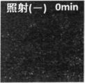
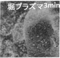
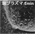
- FIG. 1 shows schematic structure of the plasma generator which concerns on embodiment. It is a perspective view which shows the 1st electrode of the plasma generator which concerns on embodiment. It is sectional drawing which shows the 1st electrode of the plasma generator which concerns on embodiment. It is sectional drawing which shows the modification of the internal electrode of the plasma generator which concerns on embodiment. It is a schematic diagram for demonstrating the manufacturing method of the protein film which concerns on embodiment. It is a microscope picture which shows protein aqueous solution. It is a microscope picture which shows what irradiated helium gas to protein aqueous solution. It is a microscope picture which shows what irradiated plasma for 3 minutes to protein aqueous solution.
- the method for producing a protein film of the present embodiment is a method for producing a membrane coagulum of proteins by irradiating an aqueous solution containing proteins with plasma.
- size of each structure of the plasma generator of this embodiment is a standard to the last. It is not necessarily limited to the numerical range described.
- FIG. 1 is a diagram showing a schematic configuration of a plasma generating device 100 of the present embodiment.
- the plasma generator 100 includes a first electrode 10, a second electrode 20, a third electrode 30, an insulating tube 40, a first insulating member 50, a second insulating member 60, and a third electrode. Insulating member 70, sealing member 80, first potential applying unit 110, and second potential applying unit 120 are provided.
- the first electrode 10 is a discharge electrode.
- the first electrode 10 also serves as a gas supply pipe for supplying a discharge gas. Therefore, the first electrode 10 is a cylindrical electrode having a cylindrical shape. As long as the 1st electrode 10 is cylindrical, other shapes, such as a polygon, may be sufficient.
- a micro hollow H1 is formed at the tip of the first electrode 10 as will be described later.
- One tip portion of the first electrode 10 is disposed inside the insulating tube 40.
- the other tip portion of the first electrode 10 is exposed to the outside of the insulating tube 40.
- the material of the first electrode 10 is, for example, stainless steel (SUS). Of course, other metals or alloys may be used.
- the outer diameter of the first electrode 10 is, for example, in the range of 1 mm to 5 mm.
- the thickness of the first electrode 10 is, for example, in the range of 0.1 mm to 0.5 mm. It is only an example and a size other than these may be used.
- the second electrode 20 is a cylindrical electrode.
- the second electrode 20 may have other shapes such as a polygon as long as it is cylindrical.
- the second electrode 20 is formed so as to cover the first insulating member 50. Therefore, the insulating tube 40 and the first insulating member 50 are disposed inside the cylinder of the second electrode 20. That is, the second electrode 20 is disposed outside the insulating tube 40. However, the first electrode 10 is not disposed inside the cylinder of the second electrode 20.
- the first electrode 10 is positioned inside the extended cylinder.
- the second electrode 20 is sandwiched between the first insulating member 50 and the second insulating member 60. Therefore, the second electrode 20 is entirely covered with an insulator.
- the material of the second electrode 20 is, for example, aluminum. Of course, other metals (including alloys) may be used.
- the thickness of the second electrode 20 is about 1 mm.
- the third electrode 30 is a cylindrical electrode.
- the third electrode 30 may have other shapes such as a polygon as long as it is cylindrical.
- the third electrode 30 is formed so as to cover the second insulating member 60. Therefore, in the cylinder of the third electrode 30, the insulating tube 40, the first insulating member 50, the second electrode 20, and the second insulating member 60 are arranged in this order from the center of the cylinder. Has been. That is, the third electrode 30 is disposed outside the insulating tube 40.
- the third electrode 30 is disposed at a position farther than the second electrode 20 when viewed from the insulating tube 40.
- the third electrode 30 is sandwiched between the second insulating member 60 and the third insulating member 70. Therefore, the third electrode 30 is entirely covered with an insulator.
- the material of the third electrode 30 is, for example, aluminum. Of course, other metals (including alloys) may be used.
- the thickness of the third electrode 30 is about 1 mm.
- the insulating tube 40 is a casing of the plasma generator 100.
- the insulating tube 40 is disposed between the first electrode 10 and the second electrode 20.
- the first electrode 10 is disposed inside the insulating tube 40, and the second electrode 20 and the third electrode 30 are disposed outside the insulating tube 40.
- As the material of the insulating tube 40 alumina, zirconia, magnesia, mullite, glass, and other materials can be used.
- the inner diameter of the insulating tube 40 is in the range of 10 mm to 30 mm.
- the thickness of the insulating tube 40 is in the range of 0.2 mm to 2 mm.
- the length of the insulating tube 40 is in the range of 10 cm to 15 cm.
- One end of the insulating tube 40 is an opening 41 that is open. And as shown in FIG. 1, the opening part 41 is a plasma irradiation opening which irradiates plasma.
- the first electrode 10 protrudes from an end 42 of the insulating tube 40 opposite to the opening 41. At the end portion 42, the gap between the insulating tube 40 and the first electrode 10 is sealed with a sealing member 80.
- a gas supply unit (not shown) is provided on the opposite side of the first electrode 10 to the micro hollow H1. The gas supply unit communicates with the inside of the cylinder of the first electrode 10 via a tube or the like. Therefore, the plasma generator 100 can supply the discharge gas in the direction of the arrow D1 in FIG.
- the first insulating member 50 is for improving the insulation resistance of the insulating tube 40.
- the first insulating member 50 is formed along the outer periphery of the insulating tube 40.
- As the first insulating member 50 polyimide, Teflon (registered trademark), or the like can be used. Other materials can also be used. Here, if a tape-like thing is used, it will be easy to wind around the outer peripheral part of the insulating tube 40.
- the second insulating member 60 is disposed at a position between the second electrode 20 and the third electrode 30.
- the material of the second insulating member 60 may be the same as that of the first insulating member 50.
- the third insulating member 70 is disposed at a position outside the third electrode 30.
- the material of the third insulating member 70 may be the same as that of the first insulating member 50.
- the length of the third electrode 30 in the axial direction of the insulating tube 40 (vertical direction in FIG. 1) is shorter than the length of the second electrode 20 in the axial direction of the insulating tube 40. Then, when viewed in the axial direction of the insulating tube 40 (vertical direction in FIG. 1), both ends of the third electrode 30 are located on the inner side than both ends of the second electrode 20. Therefore, the electrode closest to the first electrode 10 is not the third electrode 30 but the second electrode 20.
- the first potential applying unit 110 is for applying a potential to the first electrode 10. Therefore, the first potential applying unit 110 is electrically connected to the first electrode 10.
- the first potential applying unit 110 can apply a high voltage obtained by boosting a commercial AC (50 Hz, 60 Hz) power supply 100V.
- a high frequency component of about 10 kHz or more and 100 kHz or less may be superimposed by an inverter configuration.
- the first potential applying unit 110 applies a potential to the first electrode 10, a voltage is applied between the first electrode 10 and the second electrode 20.
- the second potential applying unit 120 is for applying a potential to the third electrode 30. Therefore, the second potential applying unit 120 is electrically connected to the third electrode 30. The second potential applying unit 120 is grounded, for example. At this time, a zero potential is applied to the third electrode 30. Alternatively, the second potential applying unit 120 may apply a constant potential other than the zero potential to the third electrode 30 or may apply a periodically changing potential. Thus, since the second potential applying unit 120 applies a potential to the third electrode 30, a voltage is applied to the second electrode 20 via the insulating member 60.
- a double electrode structure having a second electrode 20 and a third electrode 30 is provided outside the insulating tube 40.
- a second insulating member 60 is between the second electrode 20 and the third electrode 30. Since the double electrode structure is thus formed, the pulsed impact electric field applied in the thickness direction of the insulating tube 40 disposed between the first electrode 10 and the second electrode 20 is moderated to some extent. That is, the formation of a large electric field locally between the inside of the cylinder of the insulating tube 40 and the outside of the cylinder is suppressed. Therefore, the insulating tube 40 is difficult to break down. Therefore, the downsized plasma generator 100 is a stable plasma generation source.
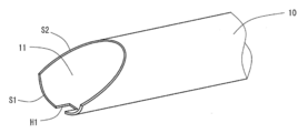
- FIG. 2 is a perspective view showing the periphery of the distal end portion 11 of the first electrode 10.
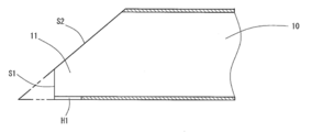
- FIG. 3 is a cross-sectional view showing a cross section including the center of the cylinder of the first electrode 10 and the micro hollow H1.
- the tip 11 of the first electrode 10 has an end surface S1 and a surface S2.
- the end surface S1 is a protruding portion that protrudes outward in the axial direction of the first electrode 10 from the surface S2. That is, the tip 11 of the first electrode 10 is not axially symmetric.
- a micro hollow H1 is formed on the end surface S1.
- the micro hollow H1 is a slit-like groove.
- the depth of the micro hollow H1 is in the range of 0.3 mm or more and 0.5 mm or less.
- the width of the micro hollow H1 is in the range of 0.1 mm or more and 0.3 mm or less.
- the electric field strength of the electric field formed between the first electrode 10 and the second electrode 20 is proportional to the voltage applied between them, and inversely proportional to the distance between them. Therefore, the potential applied by the first potential applying unit 110 and the distance between the first electrode 10 and the second electrode 20 are important.
- the outer diameter of the insulating tube 40 is designed to be small, and the distance between the first electrode 10 and the second electrode 20 is designed to be large. That is, the position of the end surface S ⁇ b> 1 of the first electrode 10 can be arranged at a position relatively far from the position of the second electrode 20.
- the distance between the position of the end surface S1 of the first electrode 10 and the position on the end 42 side of the second electrode 20 is preferably in the range of about 8 mm to 35 mm.
- the first electrode 10 shown in FIGS. 1 to 3 is used as the internal electrode arranged inside the insulating tube 40.
- the shape of the internal electrode is not limited to the first electrode 10.
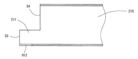
- the internal electrode 210 shown in FIG. 4 may be used.
- the tip portion 211 of the internal electrode 210 has an end surface S3 and a surface S4.
- the end surface S3 is a protrusion that protrudes outward in the axial direction of the internal electrode 210 from the surface S4.
- the tip 211 of the internal electrode 210 is not axially symmetric.
- a hollow H12 is formed on the end surface S3. In this way, the hollow H12 is formed at a portion that protrudes most outward in the axial direction.
- micro hollow H1 is formed on the end surface S1 of the first electrode 10.
- a plurality of micro hollows H1 may be formed on the end surface S1.
- the second electrode 20 and the third electrode 30 are cylindrical electrodes. However, it does not have to be cylindrical. However, it is necessary that the second electrode is located between the first electrode 10 and the third electrode.
- Plasma to be generated Plasma generated by the plasma generator 100 is non-equilibrium atmospheric pressure plasma.
- the flow rate of the discharge gas is preferably in the range of 0.5 slm to 5 slm.
- the plasma density of the generated plasma is about 1 ⁇ 10 13 cm ⁇ 3 to 1 ⁇ 10 15 cm ⁇ 3 .
- a rare gas is used as the discharge gas. Plasma irradiated from the opening 41 is mixed with the atmosphere. For this reason, various radicals derived from oxygen and nitrogen are generated.
- Protein aqueous solution In this embodiment, plasma is irradiated to protein aqueous solution. Then, the protein aqueous solution containing protein is demonstrated.
- This protein aqueous solution is an aqueous solution in which protein is mixed with ultrapure water.
- Purified albumin can be used as the protein. Examples include ovalbumin, bovine serum albumin (BSA), and fetuin. One or more of these may be used.
- BSA bovine serum albumin
- fetuin fetuin
- the method for producing a protein film of the present embodiment includes a protein aqueous solution preparation step of mixing a protein in an aqueous solvent to prepare a protein aqueous solution, and a plasma irradiation step of irradiating the protein aqueous solution with plasma generated by a plasma generator.
- a protein aqueous solution preparation step of mixing a protein in an aqueous solvent to prepare a protein aqueous solution and a plasma irradiation step of irradiating the protein aqueous solution with plasma generated by a plasma generator.
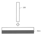
- Protein aqueous solution production process First, an aqueous protein solution is prepared. For this purpose, ultrapure water is poured into the container. And protein is mixed with the ultrapure water in a container. A purified protein is used as a protein to be mixed. If the protein has not been purified, purification is performed. Thereby, protein aqueous solution PAS1 (refer FIG. 5) is produced.
- the aqueous protein solution PAS1 is irradiated with plasma using a plasma generator 100.
- the discharge gas plasma gas
- the protein in the protein aqueous solution PAS1 is polymerized to form a protein film.
- the protein film thus formed can be easily taken out.
- the produced protein film has a plasma density of about 1 ⁇ 10 13 cm ⁇ 3 or more and 1 ⁇ 10 15 cm ⁇ 3 or less as described above.
- the protein coagulates in an irradiation time of several tens of seconds to several tens of minutes.
- the diameter of the opening 41 of the plasma generator 100 is about several mm.
- the flow rate of the discharge gas is about 0.5 slm to 5 slm. For this reason, the number of ions and radicals irradiated to the protein aqueous solution is very small compared to the Avogadro constant. Therefore, it is considered that the protein membrane of this embodiment is hardly denatured compared to the protein denatured using a denaturant and a reducing agent.
- Modification 6-1 Raw material of protein aqueous solution
- a protein aqueous solution containing a protein such as albumin was prepared.
- other proteins may be used.
- globulin, glutelin, prolamin and the like can be mentioned.
- an aqueous protein solution is prepared from the purified protein.
- unpurified egg white may be used as it is. Therefore, for example, egg white albumin, bovine serum albumin (BSA), fetuin, and unpurified egg white can be used as proteins.
- the method for producing a protein film of the present embodiment includes a protein aqueous solution production step of producing a protein aqueous solution and a plasma irradiation step of irradiating the protein aqueous solution with plasma.
- a protein film can be suitably formed by irradiating plasma with a high plasma density.
- Plasma Generator Each size of the plasma generator used in this experiment was as follows. The distance from the opening 41 to the end of the second electrode 20 on the opening 41 side in the direction of the central axis of the cylinder was 7 mm. The length of the second electrode 20 in the cylindrical central axis direction was 20 mm. The distance between the first electrode 10 and the second electrode 20 when viewed in the direction of the central axis of the cylinder was 10 mm. The diameter of the opening 41 was 1 mm.
- Plasma conditions He gas was used as the discharge gas.
- the flow rate of the discharge gas was 2 slm.
- a plasma flow having a plasma irradiation diameter of about 1 mm was observed with a length of about 4 cm.
- Protein aqueous solution Milli-Q (registered trademark) water was used as ultrapure water.
- Three types of protein aqueous solutions were prepared using the following three types of proteins as proteins.
- the proteins used were ovalbumin (OVA), ovalbumin (Egg White) and bovine serum albumin (BSA).
- OVA ovalbumin
- Egg White ovalbumin
- BSA bovine serum albumin
- OVA ovalbumin
- EW ovalbumin
- the protein concentration was varied according to the experiment.
- the volume of the aqueous protein solution irradiated with plasma was 0.3 ml.
- FIG. 6 is a photomicrograph showing the protein aqueous solution before irradiation.
- FIG. 7 is a photomicrograph showing an aqueous protein solution when He gas is irradiated without being converted into plasma.
- FIG. 8 is a photomicrograph showing the aqueous protein solution when irradiated with plasma for 3 minutes.
- FIG. 9 is a photomicrograph showing the aqueous protein solution when irradiated with plasma for 1 minute. As shown in FIGS. 8 and 9, when the plasma was irradiated, a protein-like coagulum of protein was generated in the protein aqueous solution.
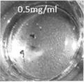
- FIG. 10 is a photograph showing a protein aqueous solution when plasma is irradiated to a protein aqueous solution having an ovalbumin (OVA) concentration of 0.5 mg / ml.
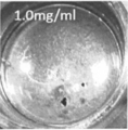
- FIG. 11 is a photograph showing a protein aqueous solution when plasma is irradiated to a protein aqueous solution having an ovalbumin (OVA) concentration of 1.0 mg / ml.
- FIG. 12 is a photograph showing a protein aqueous solution when plasma is irradiated on the protein aqueous solution having an ovalbumin (OVA) concentration of 5.0 mg / ml.
- a film-like coagulum is not formed.
- a film-like coagulum is formed.
- a relatively large film-like coagulum is formed.
- OVA ovalbumin
- FIG. 13 is a photograph showing a protein film in an aqueous protein solution after irradiation with plasma.
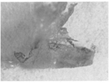
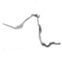
- FIG. 14 is a photograph showing the protein film taken out from the protein aqueous solution.
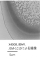
- FIG. 15 is an electron micrograph of an enlarged protein film. The magnification in FIG. 15 is 4000 times.
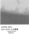
- FIG. 16 is an electron micrograph of an enlarged protein film. The magnification in FIG. 16 is 20000 times.
- the proteins are coagulated with a certain gap. Therefore, it is considered that the protein is hardly denatured.
- the protein film is almost transparent.
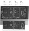
- FIG. 17 is a photograph showing a case where a protein aqueous solution mixed with egg white albumin (EW) as a protein is irradiated with plasma.
- EW egg white albumin
- photographs are arranged on the upper and lower stages. The top photo and the photo just below it are the same photo. However, in the lower photograph, a circular or oval mark is added to show the protein film.
- a ruler is arranged between the upper and lower photographs. This is to show the size of the experimental container (chamber slide) and the protein film.
- the concentration of ovalbumin (EW) was 20 mg / ml.
- the irradiation distance of plasma was 18 mm.
- the plasma irradiation time was 30 seconds.
- the plasma irradiation time was 3 minutes.
- the plasma irradiation time was 16 minutes.
- the plasma irradiation time was 21 minutes. As shown in FIG. 17, the longer the plasma irradiation time, the larger the protein film grew.
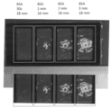
- FIG. 18 is a photograph showing a case where a protein aqueous solution mixed with bovine serum albumin (BSA) as a protein is irradiated with plasma.
- BSA bovine serum albumin
- the concentration of bovine serum albumin (BSA) was 20 mg / ml.
- the irradiation distance of plasma was 18 mm. In the first photograph from the left in FIG. 18, the plasma irradiation time was 30 seconds. In the second photograph from the left, the plasma irradiation time was 1 minute. In the third photograph from the left, the plasma irradiation time was 2 minutes. In the rightmost photo, the plasma irradiation time was 3 minutes. As shown in FIG. 18, the protein film grew larger as the plasma irradiation time was longer. Even when the plasma irradiation time was about 30 seconds, a protein film was slightly formed.
- Plasma irradiation distance is the distance from the irradiation port of the plasma generator to the liquid surface of the protein aqueous solution.
- the plasma irradiation distance 13 mm, 18 mm, and 23 mm were adopted.
- the concentration of ovalbumin was 20 mg / ml.
- the plasma irradiation distance 13 mm, the protein film was the largest.
- the plasma irradiation distance 23 mm, the protein film was the smallest.
- the shorter the plasma irradiation distance the larger the protein film grew.
- a protein film could be formed by irradiating plasma to any of the three types of protein aqueous solutions.
- the protein film produced by this protein film production method can be used as, for example, a bandage. Alternatively, it can be applied to the production of albumin preparations. It can also be used as other industrial materials.
- SYMBOLS 100 DESCRIPTION OF SYMBOLS 100 ... Plasma generator 10 ... 1st electrode 20 ... 2nd electrode 30 ... 3rd electrode 40 ... Insulating tube 50 ... 1st insulating member 60 ... 2nd insulating member 70 ... 3rd insulating member 80 ... Sealing member 110 ... first potential applying unit 120 ... second potential applying unit H1, H12 ... micro hollow S1, S3 ... end face S2, S4 ... surface PAS1 ... protein aqueous solution
Landscapes
- Engineering & Computer Science (AREA)
- Physics & Mathematics (AREA)
- Plasma & Fusion (AREA)
- Chemical & Material Sciences (AREA)
- Health & Medical Sciences (AREA)
- Manufacturing & Machinery (AREA)
- Analytical Chemistry (AREA)
- Spectroscopy & Molecular Physics (AREA)
- Toxicology (AREA)
- Medicinal Chemistry (AREA)
- Polymers & Plastics (AREA)
- Organic Chemistry (AREA)
- Chemical Kinetics & Catalysis (AREA)
- Materials Engineering (AREA)
- Oral & Maxillofacial Surgery (AREA)
- Thermal Sciences (AREA)
- Mechanical Engineering (AREA)
- Fluid Mechanics (AREA)
- Treatments Of Macromolecular Shaped Articles (AREA)
- Plasma Technology (AREA)
- Materials For Medical Uses (AREA)
- Manufacture Of Macromolecular Shaped Articles (AREA)
- Physical Or Chemical Processes And Apparatus (AREA)
Priority Applications (1)
| Application Number | Priority Date | Filing Date | Title |
|---|---|---|---|
| US15/352,436 US20170107342A1 (en) | 2014-05-16 | 2016-11-15 | Protein film production method |
Applications Claiming Priority (2)
| Application Number | Priority Date | Filing Date | Title |
|---|---|---|---|
| JP2014102455A JP6519039B2 (ja) | 2014-05-16 | 2014-05-16 | タンパク質膜の製造方法 |
| JP2014-102455 | 2014-05-16 |
Related Child Applications (1)
| Application Number | Title | Priority Date | Filing Date |
|---|---|---|---|
| US15/352,436 Continuation US20170107342A1 (en) | 2014-05-16 | 2016-11-15 | Protein film production method |
Publications (1)
| Publication Number | Publication Date |
|---|---|
| WO2015174094A1 true WO2015174094A1 (ja) | 2015-11-19 |
Family
ID=54479642
Family Applications (1)
| Application Number | Title | Priority Date | Filing Date |
|---|---|---|---|
| PCT/JP2015/002450 Ceased WO2015174094A1 (ja) | 2014-05-16 | 2015-05-14 | タンパク質膜の製造方法 |
Country Status (3)
| Country | Link |
|---|---|
| US (1) | US20170107342A1 (enExample) |
| JP (1) | JP6519039B2 (enExample) |
| WO (1) | WO2015174094A1 (enExample) |
Families Citing this family (3)
| Publication number | Priority date | Publication date | Assignee | Title |
|---|---|---|---|---|
| JP6664046B2 (ja) * | 2016-03-07 | 2020-03-13 | 国立研究開発法人産業技術総合研究所 | プラズマ照射処理装置、その評価装置及び評価方法、その制御装置及び制御方法、並びに、膜の製造方法 |
| CN112638471B (zh) * | 2019-06-24 | 2025-07-11 | 永进生物科技股份有限公司 | 包括二进气口的电浆装置 |
| JP7386275B2 (ja) | 2022-02-18 | 2023-11-24 | 日本特殊陶業株式会社 | 溶液処理装置及び溶液処理方法 |
Citations (3)
| Publication number | Priority date | Publication date | Assignee | Title |
|---|---|---|---|---|
| JP2007535666A (ja) * | 2004-04-30 | 2007-12-06 | ヴラームス インステリング ヴール テクノロギシュ オンデルゾーク (ヴイアイティーオー) | 大気圧プラズマ技術を用いる生体分子固定化 |
| WO2012070680A1 (ja) * | 2010-11-26 | 2012-05-31 | 国立大学法人東京工業大学 | コラーゲン非線維化成形体及びその製造方法 |
| JP2014218453A (ja) * | 2013-05-07 | 2014-11-20 | 国立大学法人東京工業大学 | コラーゲン成形体及びその製造方法 |
Family Cites Families (1)
| Publication number | Priority date | Publication date | Assignee | Title |
|---|---|---|---|---|
| JP6429490B2 (ja) * | 2014-05-12 | 2018-11-28 | 多木化学株式会社 | コラーゲン線維架橋多孔体 |
-
2014
- 2014-05-16 JP JP2014102455A patent/JP6519039B2/ja not_active Expired - Fee Related
-
2015
- 2015-05-14 WO PCT/JP2015/002450 patent/WO2015174094A1/ja not_active Ceased
-
2016
- 2016-11-15 US US15/352,436 patent/US20170107342A1/en not_active Abandoned
Patent Citations (3)
| Publication number | Priority date | Publication date | Assignee | Title |
|---|---|---|---|---|
| JP2007535666A (ja) * | 2004-04-30 | 2007-12-06 | ヴラームス インステリング ヴール テクノロギシュ オンデルゾーク (ヴイアイティーオー) | 大気圧プラズマ技術を用いる生体分子固定化 |
| WO2012070680A1 (ja) * | 2010-11-26 | 2012-05-31 | 国立大学法人東京工業大学 | コラーゲン非線維化成形体及びその製造方法 |
| JP2014218453A (ja) * | 2013-05-07 | 2014-11-20 | 国立大学法人東京工業大学 | コラーゲン成形体及びその製造方法 |
Non-Patent Citations (3)
| Title |
|---|
| BURKE K. CHAN: "Robust and Semi-Interpenetrating Hydrogels from Poly(ethylene glycol) and Collagen for Elastomeric Tissue Scaffolds", MACROMOL. BIOSCI., vol. 12, no. 11, November 2012 (2012-11-01), pages 1490 - 1501, XP055236436 * |
| NAOKI KOSHIMIZU, GAMMA-CROSSLINKED COLLAGEN GEL WITHOUT FIBRILS: ANALYSIS OF STRUCTURE AND HEAT STABILITY, BIOSCIENCE, BIOTECHNOLOGY, AND BIOCHEMISTRY, vol. 73, no. 9, 23 September 2009 (2009-09-23), pages 1915 - 1921, XP055236435 * |
| TAKASHI YOSHIDA ET AL.: "Hoshasen Shosha o Mochiita Apatite/Collagen Fukugotai ni Okeru Butsuri Kakyo no Seigyo", THE CERAMIC SOCIETY OF JAPAN NENKAI KOEN YOKOSHU, vol. 2013, 11 March 2013 (2013-03-11), pages 1P106 * |
Also Published As
| Publication number | Publication date |
|---|---|
| US20170107342A1 (en) | 2017-04-20 |
| JP6519039B2 (ja) | 2019-05-29 |
| JP2015218245A (ja) | 2015-12-07 |
Similar Documents
| Publication | Publication Date | Title |
|---|---|---|
| JP6519039B2 (ja) | タンパク質膜の製造方法 | |
| Jin et al. | Effects and mechanism of ultrasound pretreatment on rapeseed protein enzymolysis | |
| Ikehara et al. | Plasma blood coagulation without involving the activation of platelets and coagulation factors | |
| CN105551923B (zh) | 等离子体生成装置及等离子体生成方法 | |
| RU94015846A (ru) | Способ и устройство для отделения взвешенных частиц | |
| KR20170095804A (ko) | 이차원 막 소재에 기반을 둔 혈액 투석 및 혈액 여과 막과 이를 이용하는 방법 | |
| US20230414811A1 (en) | Liquid processing apparatus with atmospheric, low-temperature plasma activation | |
| JP6511440B2 (ja) | プラズマ照射方法、およびプラズマ照射装置 | |
| CN206761952U (zh) | 一种大气压柔性冷等离子体射流内窥镜灭菌装置 | |
| CN106693009B (zh) | 一种大气压柔性冷等离子体射流内窥镜灭菌装置及方法 | |
| JP2015076143A (ja) | プラズマ発生装置 | |
| JP2009114001A (ja) | オゾン発生装置 | |
| CN1257687C (zh) | 一种高压脉冲电场处理装置 | |
| JP2009234900A (ja) | 水中オゾナイザ | |
| JP2002516088A (ja) | 生物学的物体の浸透のための方法及びデバイス | |
| JP2014032787A (ja) | 液中放電装置 | |
| JP2015218245A5 (enExample) | ||
| JP2012197246A (ja) | タンパク質の低分子化方法 | |
| Prihandana et al. | Electropolishing of microchannels and its application to dialysis system | |
| JP2017144422A (ja) | 液体処理装置 | |
| KR101950065B1 (ko) | 플라즈마 발생 필름 생산 방법 | |
| JP2023156780A (ja) | 液体処理装置及び液体処理方法 | |
| JP2013180249A (ja) | 水浄化装置 | |
| JP2016032806A (ja) | 液体処理装置 | |
| JP2012152712A (ja) | 液中プラズマ発生装置及びそれに使用する電極装置 |
Legal Events
| Date | Code | Title | Description |
|---|---|---|---|
| 121 | Ep: the epo has been informed by wipo that ep was designated in this application |
Ref document number: 15793589 Country of ref document: EP Kind code of ref document: A1 |
|
| NENP | Non-entry into the national phase |
Ref country code: DE |
|
| 122 | Ep: pct application non-entry in european phase |
Ref document number: 15793589 Country of ref document: EP Kind code of ref document: A1 |